1
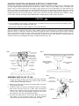
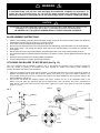
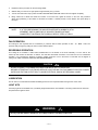
A
B
994 Series
C
Ceiling Fans
Inspect contents of carton for possible shipping and handling damage. The blades are a carefully matched set. If one or more
blades from a carton has been damaged, arrange to have all the blades replaced.
BLADES ARE PACKED AS A MATCHED SET AT THE FACTORY IN ORDER TO ENSURE SMOOTH FAN OPERATION.
If more than one fan is being installed, be careful to attach blades removed from one carton to the same fan.
DO NOT MIX BLADES FROM DIFFERENT CARTONS.
CHART 1
FAN
MODEL
SERIES
NO. OF
BLADES
FAN BLADE NO. OF CARTONS
SPAN “C” FAN SHIPPED IN
994
GILLESPIE
5
52
994PF
PORCH FAN**
5
52
MINIMUM
DIM. A
DISTANCE
DIM. B
FAN
WEIGHT (LB.)
USE CONTROL
MODEL NO.
1
13.00
12.5
20
9290
1
13.00
12.5
20
9290*
** Damp Location Fan
* Installer must take adequate precautions to insure water does not enter installation.
Refer to Marley Engineered Products Sales Literature for Light Kit Models available.
WARNING: To reduce the risk of fire or electrical shock, this fan should only be used with the controls listed in Chart 1.
Use only Light Kits marked “Suitable for use in Damp locations” with Damp location fans.
Installation & Maintenance Instructions
WARNING
!
Read Carefully - These instructions are written to help you prevent difficulties that might arise during installation. Studying
the instructions first may save you considerable time and money later. Observe the following procedures, and cut your installation time to a minimum. CAUTION - TO REDUCE RISK OF FIRE AND ELECTRIC SHOCK:
1. To avoid possibility of serious injury or electrical shock, the installer must disconnect the electric circuit supplying power
to the fan outlet box prior to installing this fan. Turning the power off at the fan switch or speed control (on / off) is not an
acceptable method to prevent electrical shock.
2. To reduce the risk of fire, electric shock or personal injury, mount fan to an outlet box marked “Acceptable for Fan Support”
and use mounting screws provided with outlet box. (Marley Engineered Products Model 925 HANG-SAFETM Outlet Box is
U.L. Listed for this purpose. U.S. patent number 4,788,383.) Installer must take adequate precautions to prevent water
entry into installation where field installed wiring will be housed.
SAVE THESE INSTRUCTIONS
a
CAUTION
!
1. Before attaching the ceiling fan to an outlet box with a hanger bracket, be sure that the outlet box is fastened securely
to the ceiling supports.
2. Check to be sure that the outlet box is marked as “ACCEPTABLE FOR FAN SUPPORT”. (Marley Engineered Products
Model 925 HANG-SAFETM Outlet Box is U.L. Listed for this purpose. U.S. Patent Number 4,788,383.)
3. The outlet box and ceiling support should be checked to be sure that it will support at least 50 lbs. of load.
4. Electrical connections and circuit wiring should be in accordance with the National Electrical Code and/or all local codes
that may apply.
5. If you are unfamiliar with electrical circuitry, acquire the services of a qualified electrician.
6. If a light kit is to be installed to the fan, add the combined light fixture wattage to the fan wattage to determine the total
wattage rating of the installation.
7. After installation, blades must be a minimum of seven (7) feet above the floor. Do not install on ceilings less than eight
(8) feet high.
8. Do not use this product in a corrosive or explosive atmosphere.
9. The important safeguards and instructions appearing in this manual are not meant to cover all possible conditions and
situations that may occur. It must be understood that common sense, caution and care are factors which cannot be built
into any product. These factors must be supplied by the person(s) caring for and operating the unit.
INSTALLING FAN BALL HANGER MOUNTING BRACKET
See Chart 1 for approximate weight for each model of fan. This weight factor,
coupled with the slight fan gyration that can occur during operation, requires
that a strong ceiling support be provided for attaching the hanger bracket
supplied. Refer to Fig. 1 for installation. Secure mounting bracket accordingly.
1.
2.
Check to be sure the electrical outlet box is mounted to the ceiling
securely and that it is marked “acceptable for ceiling fan support.”
(Marley Engineered Products Model 925 Hang-SafeTM Outlet Box is U.L.
Listed for this purpose.) If the outlet box is loose, secure it.
CONSTRUCTION
MEMBER
FIELD
SUPPLY
WIRING
Position the slotted holes in the ball hanger bracket feet to allow the
threaded bolts of the installed Model 925 Outlet Box through them.
(See Fig. 1.) Thread the locknuts provided with the Marley Engineered
Products Model 925 onto the threaded bolts and tighten securely. Make
sure the ball hanger bracket is snugly and securely mounted to the outlet
box after tightening the locknuts.
FIG. 1
BALL
HANGER
BRACKET
Check to be sure the outlet box is securely mounted to the ceiling and
marked “acceptable for ceiling fan support.”
B.
Align the slotted holes in the ball hanger bracket with the fan mounting
holes in the outlet box.
C.
Secure the ball hanger bracket to the outlet box using the two screws
provided in the fan’s hardware bag.
GROUND
WIRE
BALL
HANGER
BALL HANGER
DOWNROD
NOTE: LEADS FROM FAN SHOULD PASS
THROUGH DOWNROD AS SHOWN
a
CAUTION
1.
2.
!
To reduce the risk of personal injury, use only the two steel screws (and
lock washers) provided with the fan for mounting to the outlet box.
Some outlet boxes acceptable for fan support may not require the use of
these screws due to the uniqueness of their design. Consult their accompanying instruction sheet for ball hanger bracket installation instructions if
the above methods do not apply.
—2—
CANOPY
MOUNTING
SCREWS
OUTLET BOX
HANGER BRACKET
LOCK NUTS
Some outlet boxes that are acceptable for fan support (other than Marley
Engineered Products Model 925) use screws to fasten the fan mounting
bracket to them. This type of outlet box will require following these general
instructions for installation of the ball hanger bracket to the outlet box.
A.
REINFORCED OUTLET
BOX (MODEL 925 HANG
SAFETM )
CEILING
MATERIAL
ASSEMBLING BALL HANGER TO MOTOR ASSEMBLY
Ceiling height and the desired distance above the floor the fan is to be located will dictate the length of ball hanger
downrod (or stem) required to hang the motor assembly.
Installation on ceilings 8-10 feet high can be accomplished with the ball hanger downrod (stem) supplied. The fan is
shipped from the factory with a 3-1/2” ball hanger downrod (stem) and is designed for ceilings 8’ high.
For higher ceiling applications, replace the 3-1/2” downrod (stem) with a Marley Engineered Products Model C902 stem accessory (downrod) in 12”, 18”, 24” and 36” lengths. These downrods are offered in a color to match each Marley Engineered
Products fan and are available from your local Marley Engineered Products distributor. Additional installation instructions are
included with each downrod (stem) accessory kit.
a
CAUTION
!
In all cases, whichever downrod length you select, take care to prevent the bottom edge of the blade from being less than 7 feet from the floor.
1.
Guide the three leads coming from the top of the motor assembly through the small end of the ceiling canopy and then
through the bottom end of the ball hanger downrod and out the top. (See Fig. 2.)
2.
Remove the thru pin from the downrod mounting hub (if installed). If
thru pin is not installed, you will find it and the cotter pin in the fan’s
hardware bag.
3.
FIG. 2
Unscrew the two set screws in the downrod mounting hub just far
enough to prevent prematurely dropping the downrod (stem).
CANOPY MOUNTING
SCREWS
4.
5.
Place the downrod (stem) into the downrod mounting hub, being
careful not to cut or pinch the leads.
BALL HANGER SET
SCREW
Align the thru pin holes in the downrod mounting hub with the
thru pin holes in the downrod (stem).
6.
Insert the thru pin through the thru pin holes in the assembled
downrod (stem) and downrod mounting hub. Insert the cotter pin
through the hole in the end of the thru pin. Separate the cotter pin
legs and fold them back to prevent removal of the cotter pin and
secure the thru pin (See Fig. 4). Some units will employ a hair
spring cotter pin which once snapped in place will not require
bending the pin’s legs back.
7.
Uniformly retighten the set screws to secure the downrod (stem) in
a vertical position. Failure to do this could result in a crooked fan
installation.
BALL HANGER
SET SCREW
BALL HANGER
CEILING CANOPY
DOWNROD MOUNTING
HUB SET SCREWS
MOTOR HOUSING
TOP COVER
COTTER
PIN
BALL HANGER
FIG. 3
BALL HANGER
BRACKET
BALL
HANGER
DOWNROD
FIG. 4
CEILING CANOPY
BALL HANGER
DOWNROD
THRU
PIN
(CLEVIS)
COTTER PIN HOLE
THRU PIN HOLE
THRU PIN (CLEVIS)
COTTER PIN
DOWNROD MOUNTING
HUB SET SCREWS
DOWNROD MOUNTING
HUB SET SCREW
a
CAUTION
!
Set screws holding the downrod to the downrod mounting hub and the ball hanger to the downrod must be tightened securely.
Failure to properly tighten these screws could result in the motor detaching from the downrod and a poor electrical ground connection respectively.
—3—
HANGING FAN MOTOR AND MAKING ELECTRICAL CONNECTIONS
Lift motor with ball hanger assembly attached and position into ball hanger bracket, making sure slot in ball hanger locks
onto ball hanger bracket’s ball locking stud. Connect motor leads to 120V, 60 cycle supply wiring in accordance with
FIgures 5 and 13. Connect ground wire from supply to green ground wire on top of ball hanger. The white lead from the
motor is connected to the white supply wire. The black lead from the motor is connected to the black supply wire to permit
fan operation. Both the black and blue fan motor leads are connected to the black supply wire when a light kit is to be
installed, permitting both fan and light operation. (See Figure 5.) Note that connections should be made outside the canopy.
In some cases, it may be necessary to splice additional wire to existing wiring in order to make connections.
a
CAUTION
!
1. Electrical connections should be in accordance with the National Electrical Code and/or all local codes that may apply.
2. To avoid possibility of serious injury or electrical shock, the installer must disconnect the electrical circuit supplying power
to the fan outlet box prior to installing the ceiling fan.
3. Damp location ceiling fans must be installed in a GFCI protected circuit.
Once the electrical connections have been made, carefully position the leads with the connections pointed upwards
inside the canopy or outlet box. Position the ground wire (green and bare connected wires) and the white connected
wires on one side of the outlet box and/or canopy; the black connected wires on the opposite. Slide the canopy up to the
ceiling making sure the canopy mounting screw heads pass through the key-way slots. Rotate the canopy towards the
narrow end of the key-way and tighten the canopy mounting screws. See Fig. 5 & 6.
FIG. 5
WHITE CONNECTED WIRES
120V. 60HZ. SUPPLY
FIG. 6
OUTLET BOX APPROVED
FOR FAN SUPPORT
CEILING MATERIAL
BLUE
BLACK CONNECTED
WIRES
CANOPY MOUNTING
SCREWS
BALL HANGER DOWNROD
DOWNROD MOUNTING HUB
SET SCREWS
FLUSH WITH
CEILING
CEILING
GREEN & BARE FIELD
WIRE (GND.) CONNECTION
BALL HANGER BRACKET
CHECK DOWNROD
MOUNTING HUB SET
SCREWS
BALL HANGER SET
SCREW
CANOPY MOUNTING
SCREWS
BALL HANGER
CANOPY IN DOWN
POSITION
MOTOR HOUSING
TOP COVER
FIG. 7
ASSEMBLE SWITCH CUP TO FAN
1.
Connect the switch cup plug to the fans connector plug, taking care
to align the guides in each part. This ensures proper electrical
circuit connection (matching lead colors).
2.
Remove one screw from the switch cup mounting plate, and loosen
the remaining two screws.
3.
Position the switch cup onto fan’s remaining two switch cup mounting
plate screws and twist to latch cup in place. With cup latched at
extreme ends of latching cutouts, replace and secure the removed
screw into the switch cup mounting plate through the cup’s screw
hole. Tighten the other two screws loosened in Step 2.
4.
Reconnect the supply power to the fan circuit. Make sure fan’s pull
chain switch is in the off position (hub is not turning) following
connection of the power and prior to performing the next steps.
—4—
SWITCH CUP
MOUNTING PLATE
SWITCH CUP
SECURING SCREWS
FAN
SWITCH CUP
FAN PULL CHAIN
SWITCH
CONNECTOR
PLUGS
WARNING
!
DO NOT ATTEMPT
to assemble blades until you have read thoroughly and understand completely all instructions. To
reduce the risk of personal injury, do not bend the blade brackets when installing the brackets,
balancing the blades, or cleaning the fan. Do not insert foreign objects in between rotating fan blades.
a
CAUTION
!
ALTHOUGH THE BLADE ARMS ARE INSPECTED AT OUR FACTORY, CARE MUST BE TAKEN IN THE
ASSEMBLY OF THE BLADES SO AS NOT TO DEFORM OR ALTER THE BLADE ARM.
BE CAREFUL NOT TO SLIDE OR SCRAPE METALLIC PARTS ON BLADE’S SURFACE.
BLADE ASSEMBLY INSTRUCTIONS
1.
2.
3.
4.
5.
6.
7.
8.
Open the motor assembly carton and remove the blades carefully, being sure not to scratch the factory finish. If the blades are
preassembled, proceed to the next section; if not, proceed as follows:
In the carton, locate the hardware bag and blade arms. (See Fig. 8)
Remove the truss-headed machine screws and washers from the hardware bag. Some assemblies may not require washers.
Insert screws (10-24 x 3/8”) through the washers, blade and into the threaded emboss on the blade arm. Assemble, but
do not tighten.
After all screws are in place in the blade assembly, alternately tighten each screw evenly until the assembly is secure.
Check assembled blade for looseness between the blade arm and blade. If present, continue tightening alternate screws until
secure.
Repeat the above procedure for the remaining blades and hardware.
Once the blade assembly is complete, proceed with installation.
ATTACHING FAN BLADES TO MOTOR HUB (See Fig. 10)
This unit is designed with the capability of being a four or five bladed fan depending on the customer’s preference.
Once the number of blades to be installed has been decided on, perform the following steps carefully to
minimize fan wobble and insure proper fan balance.
1.
2.
Please find embossed onto the motor hub the numbers 4, 5 and their guide lines. The 4 and 5 represent the number of
blades to be installed and the guide lines locate the specific screw holes to be used for that blade combination. On
some models this may be in the form of square holes (used for four blade installations) and round holes (used for five
blade installations). (See Fig. 9)
First remove and discard the transport bumpers and screws. Position the arm of the assembled blade on the
bottom of the hub. Using the guide lines align the two tapped holes in the hub with the two holes in the blade arm.
Insert the two 10-32 truss head screws into these holes. Tighten the screws down and then back them off slightly
(Approx. 11⁄2 turns).
FIG. 10
FIG. 8
FAN BLADE
SCREWS
PETAL
7 FT. MINIMUM
HEIGHT FROM
FLOOR LEVEL
MOTOR
HUB
WASHER
“10-32 X 1/2”
LONG SCREWS
BLADE ARM
BENEATH
MOTOR HUB
MOUNTING
SCREW
GUIDE LINES
BLADE ARM
FLOOR LEVEL
BLADE
QUANTITY
FIG. 9
—5—
3.
Repeat the above procedure for the remaining blades.
4.
Without delay, turn the fan on high speed for approximately one (1) minute.
5.
Turn the fan off and let it stop by itself. DO NOT TOUCH BLADES OR HUB until the fan has stopped completely.
6.
Being careful not to disturb the blade arm location on the motor hub, tighten all screws on the hub. This procedure
allows final positioning of the blades to eliminate fan wobble. If wobble persists, loosen blades and repeat Steps 4
through 6.
NOTE:
IF AFTER PERFORMING THE ABOVE PROCEDURE A WOBBLE IS STILL
APPARENT, SWITCH ONE PAIR OF ADJACENT BLADES WITHOUT
COMPLETELY TIGHTENING THE SCREWS. REPEAT STEPS 4 THRU 6.
FAN OPERATION
This ceiling fan has 3-speeds that are controlled by a pull-chain switch. Switch operation is OFF - HI - MED - LOW. The
speed is easily changed by pulling the chain to select desired speed.
REVERSIBLE OPERATION
This ceiling fan is reversible. A slide switch installed either on the bottom of the motor assembly or on the side of the
switch cap will reverse the direction of rotation. This will allow downward movement of air under the fan for summertime
operation, or by reversing the direction of rotation, upward movement of air in the winter to recirculate hot air trapped at
ceiling level. DAMP LOCATION FANS MAY NOT BE REVERSIBLE.
a
CAUTION
!
DO NOT ATTEMPT TO CHANGE FAN DIRECTION WHILE UNIT IS OPERATING!
BEFORE ATTEMPTING TO CLEAN OR SERVICE YOUR CEILING FAN, DISCONNECT ELECTRIC POWER
SUPPLYING THE FAN OUTLET BOX TO AVOID ELECTRICAL SHOCK OR PERSONAL INJURY.
LUBRICATION
The fan motor is constructed with sealed ball bearings which do not require lubrication during the life of the motor.
LIGHT KITS
Accessory light kits are available from your Marley Engineered Products Fan distributor. The wiring instructions for these kits
are packed in the light kit carton.
WARNING
!
Use only Light Kits marked “Suitable for use in Damp locations” with Damp location fans.
—6—
GENERAL INSTALLATION (OPTIONS)
Various options for installing and operating these ceiling fans and accessories are available. Wiring diagrams are shown
on the following pages. Refer to the instructions included with the light kit and/or speed control where applicable.
OPTION #1 (Fig. 11) Fan and light controlled at unit.
This installation is the simplest with all controls mounted on the fan as shipped. The light kit, if used, is controlled with the
pull-chain switch on the light kit.
OPTION #2 (Fig. 12) Fan controlled at unit. Light controlled at wall with switch or dimmer.
This option is the same as Option #1, except the light is controlled from an existing wall-mounted switch or light dimmer.
This option is designed for installations in which the fan is installed in place of a ceiling light or chandelier which was
controlled by a wall switch. No additional wiring is necessary.
FIG. 11
FIG. 12
120 V. A.C.
SUPPLY
CEILING BOX
CEILING BOX
120 V. A.C.
SUPPLY
GROUND
GROUND
BLACK
BLUE
BLACK
WHITE
GND.
WHITE
BLACK
WHITE
WHITE
WALL CONTROL
CIRCUIT
BLACK
WHITE
CEILING
CEILING
BLUE
BLACK
GREEN
GREEN
BALL HANGER GROUND
WIRE SET SCREW
BALL HANGER GROUND
WIRE SET SCREW
BALL HANGER
SET SCREW
BALL HANGER
SET SCREW
BALL HANGER
WHITE
BLACK
GROUND
BALL HANGER
CANOPY
CANOPY
MOTOR
SET SCREW
MOTOR
HOUSING
TOP
WALL MOUNTED
LIGHT SWITCH
OR DIMMER
(USE ONLY LISTED
GENERAL USE
SWITCHES)
MOTOR
HOUSING
TOP
MOTOR
SET SCREW
OPTION #3 (Fig. 13) Light controlled at unit. Fan controlled at wall by a Speed Control.
This option utilizes a speed control (See Chart 1) to operate the fan from a remote wall location. The light is controlled at
the fan. The wall control replaces the existing wall switch. No additional wiring is necessary for this installation. The Fan
switch on the unit must be left in the high speed position for the control to function properly. We suggest you cut off the
chain of the pull-chain switch after the high speed position is established on the fan.
WARNING
!
RISK OF FIRE - Fan speed switch must be set to high when wall speed control is used.
OPTION #4 (Fig. 14) Light controlled at wall. Fan controlled at wall by a Speed Control.
This option can be used when the fan is installed in place of an existing ceiling light kit. A speed control (See Chart 1) will
replace the light switch (or dimmer) in the wall that controlled the ceiling light. An additional box and switch must be
installed for this option. Follow all state and/or local building and electrical codes for this installation.
FIG. 13
FIG. 14
BLUE
BALL HANGER GROUND
WIRE SET SCREW
CEILING
GREEN
WHITE
BALL HANGER
SET SCREW
BALL HANGER
BLACK
GROUND
WHITE
BLACK
BALL HANGER GROUND
WIRE SET SCREW
BALL HANGER
CANOPY
CANOPY
MOTOR
HOUSING
TOP
WALL CONTROL
CIRCUIT
RED
GREEN
MOTOR
SET SCREW
GND.
BLACK
WHITE
MOTOR
SET SCREW
SPEED CONTROL
(USE ONLY LISTED
CONTROLS)
—7—
MOTOR
HOUSING
TOP
SPEED CONTROL
(USE ONLY LISTED
CONTROLS)
RED
WHITE
CEILING
BLUE
BALL HANGER
SET SCREW
WHITE
BLACK
WALL CONTROL
CIRCUIT
BLACK
GND.
BLACK
BLACK
WHITE
BLACK
WHITE
WHITE
GROUND
BLACK
BLACK
WHITE
CEILING BOX
120 V. A.C.
SUPPLY
GROUND
GROUND
BLACK
WHITE
CEILING BOX
120 V. A.C.
SUPPLY
WALL MOUNTED
LIGHT SWITCH
OR DIMMER
(USE ONLY LISTED
GENERAL USE
SWITCHES)
IMPORTANT FACTS ABOUT OUR FOAM PACKAGING
We’ve chosen Expanded Polystyrene Foam (EPS) packaging to cushion and protect your purchase
because of its performance and environmental advantages. EPS foam uses fewer resources and less
energy to make than alternative packaging. Efficient, lightweight and durable, EPS reduces both package
size and fuel consumption during transportation.
No ozone-depleting CFC’s have been used to manufacture EPS foam packaging.
You can now recycle CFC’s packaging through a network of manufacturer’s reprocessors and
retailers across the country. EPS is a valuable resource that can be remanufactured back into an
amazing array of recycled-content durable polystyrene products — from office supplies to videocassette
cartridges.
To locate the nearest EPS foam packaging collection site, call our RECYCLING HOTLINE at 1-800-944-8448.
Recycle EPS foam. — It’s Part of the Package! You’ll be helping us to protect the environment. Thank you.
HERE ARE SOME OF THE THINGS THAT TRAVEL SAFELY
THANKS TO EXPANDED POLYSTYRENE PACKAGING (EPS):
-Fragile electronic equipment like TV’s, VCR’s and computers.
-Perishable meats, seafood, fruit and vegetables, flowers and bottled beverages.
-Vaccines, blood plasma, organs for transport and other life saving materials.
-Cosmetics and personal care products like hair dryers and dental care appliances.
-Small household appliances like clocks, electric mixers and coffee makers.
-Subassembly parts being transported to the final manufacturing site.
-Heads (thanks to the bicycle helmets).
To recycle this EPS package, call: 1-800-944-8448
HOW TO ORDER REPAIR PARTS
In order to obtain any needed repair or replacement
parts, warranty service or technical information, please
contact Marley Engineered Products Service Center tollfree by calling 1-800-642-HEAT.
When ordering repair parts, always give the information listed as follows:
1. The Part Number
2. The Model Number
3. The Part Description
4. Date of Manufacture
Part No. 5200-2536-001
470 Beauty Spot Rd. East
Bennettsville, SC 29512 USA
ECR 35285
5/02


![eko 4000 series installation manual A [EN]:XL03](http://vs1.manualzilla.com/store/data/006898434_1-46c26fba35bf59407139a85b77984d70-150x150.png)