1
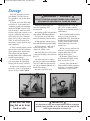
401764 XP Tiller-Cultivator_manual 5/18/10 10:51 AM Page 1
Tiller/Cultivator
with 4 Stroke Engine
OWNER’S MANUAL
401764 XP Tiller-Cultivator_manual 5/18/10 10:51 AM Page 2
Welcome
to the World of
®
Mantis XP Gardening
Here’s your new MANTIS XP Tiller…
the lightweight wonder that is making
gardening easier.
Unlike big tillers, your MANTIS XP
Tiller weighs only 34 pounds and is
like no other. So it lifts easily, handles
smoothly, tills and weeds precisely.
And, unlike other small tillers, it
features dual serpentine tines that churn
soil to ten inches deep. It creates a soft,
smooth seed bed, even
in problem soil.
It’s bigger than a mini tiller and better
than a bigger tiller!
Once you know how to use your tiller
correctly, we guarantee you’ll love it.
So first, please read this manual. It
shows, step by step, how to use your
tiller safely.
If you have questions about any topic
in this Manual, or for the name of
your local dealer, call 1-800-366-6268
toll free, Monday – Saturday, 8:00am
to 5:00pm, Eastern Time.
Table of Contents
Safety Rules & Warnings . . . . . . . . . . . . . . . . . .3-5
Safety Decals . . . . . . . . . . . . . . . . . . . . . . . . . . . .4
Engine & Fuel Warnings . . . . . . . . . . . . . . . . . . .5
Assembly . . . . . . . . . . . . . . . . . . . . . . . . . . . . . .6-9
Starting . . . . . . . . . . . . . . . . . . . . . . . . . . . . . . . .10
Additional Information . . . . . . . . . . . . . . . . . . . .11
Getting to Your Garden . . . . . . . . . . . . . . . . . . . .11
2
Tilling & Cultivating . . . . . . . . . . . . . . . . . . .12-14
Tine Positioning and Cleaning. . . . . . . . . . . . . . 14
Maintenance . . . . . . . . . . . . . . . . . . . . . . . . .15-16
Storage . . . . . . . . . . . . . . . . . . . . . . . . . . . . . . . .17
MANTIS XP Tiller Assembly Layout . . . . . . . .18
Limited Warranty Information . . . . . . . . . . . . . .20
401764 XP Tiller-Cultivator_manual 5/18/10 10:51 AM Page 3
Safety Rules & Warnings
You will notice Safety Rules and Important Notes throughout this Owners Manual. Make sure you understand
and obey these warnings for your own protection.
I. Special Safety Information
!
WARNING • DANGER
!
ATTENTION: THIS SYMBOL POINTS OUT
OUR IMPORTANT SAFETY INSTRUCTIONS.
WHEN YOU SEE THIS SYMBOL, !
HEED IT’S WARNING!! STAY ALERT!!
!
WARNING • DANGER
!
TO REDUCE THE POTENTIAL FOR ACCIDENTS, COMPLY
WITH THE SAFETY INSTRUCTIONS IN THIS MANUAL.
FAILURE TO COMPLY MAY RESULT IN SERIOUS PERSONAL
INJURY, AND/OR EQUIPMENT AND PROPERTY DAMAGE.
II. Safety & Warnings
!
WARNING • DANGER
!
IMPROPER USE OR CARE OF THIS TILLER
OR FAILURE TO WEAR PROPER PROTECTION
CAN RESULT IN SERIOUS INJURY.
READ AND UNDERSTAND THE RULES FOR SAFE OPERATION
AND ALL INSTRUCTIONS IN THIS MANUAL.
WEAR HEARING AND EYE PROTECTION.
! WARNING: The Engine Exhaust from this product contains chemicals known
to the State of California to cause cancer, birth defects or other reproductive harm.
3
401764 XP Tiller-Cultivator_manual 5/18/10 10:51 AM Page 4
III. Safety Decal Information
An important part of the safety system incorporated in this tiller
are the warning and information decals found on various parts of the
tiller. These decals must be replaced in time due to abrasion, etc. It is your
responsibility to replace these decals when they become hard to read. The
location and part numbers (P/N) of these decals are illustrated below.
P/N 400634
P/N 400631
CUTTING HAZARD; KEEP
FEET AND HANDS AWAY
FROM ROTATING TINES.
DO NOT CARRY THE TILLER
IN THIS POSITION.
CAUTION: WHEN
ASSEMBLING THE HANDLES,
MAKE SURE FUEL TANK FACES
AWAY FROM OPERATOR. THIS
IS THE REAR OF THE TILLER,
REFER TO ASSEMBLY
INSTRUCTION ON PAGE 7.
INCORRECT ASSEMBLY.
READ OWNER’S MANUAL
BEFORE USING TILLER, OR
PERFORMING ANY REPAIR
OR MAINTENANCE. KEEP
OWNERS MANUAL IN A
SAFE PLACE.
DON’T FUEL, REFUEL, OR
CHECK FUEL WHILE
SMOKING, OR NEAR AN
OPEN FLAME OR OTHER
IGNITION SOURCE.
DO NOT REACH YOUR
FINGERS AND\OR
HANDS IN BETWEEN
THE TINE BLADES
ALWAYS REMOVE THE
OUTER TINES BEFORE
REMOVING THE
INNER TINES
WEAR EAR AND EYE
PROTECTION.
DO NOT OPERATE TILLER
INDOORS OR IN POORLY
VENTILATED AREA
P/N 400635
! WARNING • DANGER !
IF THE TILLER IS USED IMPROPERLY OR SAFETY PRECAUTIONS
ARE NOT FOLLOWED, THE USERS RISK SERIOUS INJURY TO
THEMSELVES AND OTHERS. READ AND UNDERSTAND THIS
MANUAL BEFORE ATTEMPTING TO OPERATE THIS TILLER.
IV. Warnings - Do’s
Read and understand the owner’s
manual. Pay particular attention to all
sections regarding safety.
1. Always keep a firm grip on both
handles while the tines are moving and/or
the engine is running. BE AWARE!! The
tines may coast after throttle trigger is
released. Make sure tines have come to a
complete stop and engine is off before
letting go of the tiller.
2. Always maintain a firm footing and
good balance. Do not overreach while
operating the tiller. Before you start to use
the tiller, check the work area for obstacles
that might cause you to lose your footing,
balance or control of the machine.
3. Thoroughly inspect the area where
equipment is to be used and remove all
objects, which can be thrown by the
machine.
4. Always keep area clear of children,
pets, and bystanders.
5. Always stay alert. Watch what you
are doing and use common sense. Do not
4
! WARNING • DANGER !
OPERATION OF THIS EQUIPMENT MAY CREATE SPARKS THAT
CAN START FIRES AROUND DRY VEGETATION. A SPARK
ARRESTOR IS INSTALLED. THE OPERATOR SHOULD CONTACT
LOCAL FIRE AGENCIES FOR LAWS OR REGULATIONS
RELATING TO FIRE PREVENTION REQUIREMENTS.
operate unit when fatigued.
6. Always dress properly. Do not wear
loose clothing or jewelry, they might get
caught in moving parts. Use sturdy gloves.
Gloves reduce the transmission of
vibration to your hands. Prolonged
exposure to vibration can cause numbness
and other ailments.
7. While working, always wear
substantial footwear and long trousers. Do
not operate the equipment when barefoot
or wearing open sandals.
8. Always wear ear and eye protection.
Eye protection must meet ANSI Z 87.1.
To avoid hearing damage, we recommend
hearing protection be worn whenever
using the equipment.
9. To reduce fire hazard, keep the
engine, and petrol/gas storage area free of
vegetative material and excessive grease.
10. Start the engine carefully,
according to the manufacturer’s
instructions and with feet well away from
tool(s).
11. Keep all nuts, bolts and screws
tight to be sure the equipment is in safe
working condition.
12. Use extreme caution when
reversing or pulling the machine towards
you.
13. Work only in daylight or good
artificial light.
14. Always be sure of your footing on
slopes.
15. Exercise extreme caution when
changing direction on slopes.
16. Always keep a safe distance
between two or more people when
working together.
17. Always inspect your unit before
each use and ensure that all handles,
guards and fasteners are secure, operating,
and in place.
18. Always maintain and examine your
tiller with care. Follow maintenance
instructions given in manual.
19. Always store tiller in a sheltered
area (a dry place), not accessible to
children. The tiller as well as fuel should
not be stored in a house.
20. Always remove the outer set of tines
before removing the inner set of tines.
401764 XP Tiller-Cultivator_manual 5/18/10 10:51 AM Page 5
V. Warnings - Don'ts
when tines are rotating.
Don’t use tiller with one hand.
Keep both hands on handles with
fingers and thumbs encircling the
handles, while tines are moving, and
engine is running.
Don’t work on excessively steep
slopes.
Don’t overreach. Keep a good
footing at all times.
Don’t attempt to clear tines while
they are moving. Never try to remove
jammed material before switching
the engine off and making sure the
tines have stopped completely.
Don’t run with the machine,
walk.
Don’t allow children or incapable
people to operate this tiller.
Don’t let others operate tiller
without proper training.
Don’t operate while under
the influence of alcohol or drugs.
Don’t attempt to repair this tiller.
Do not stand in front of tiller
!
Have repairs made by a qualified
dealer or repairman.
See that only original Mantis®
parts are used.
Don’t operate tiller with tines
having the 3 rods extending from end
without having second set of tines
attached. Failure to have tines in
place will damage tine assembly.
Do not reach you fingers and\or
hands in between the tine blades.
Do not attempt to remove the
inner tines before removing the
outer tines.
WARNING • DANGER
!
HANDLE FUEL WITH CARE, IT IS HIGHLY FLAMMABLE. FUELING A HOT ENGINE OR NEAR AN IGNITION
SOURCE CAN CAUSE A FIRE AND RESULT IN SERIOUS PERSONAL INJURY AND/OR PROPERTY DAMAGE.
VI. Engine/Fuel Warnings - Do’s
Always use fresh gasoline. Stale
gasoline can cause damage.
Always store fuel in containers
specifically designed for this
purpose.
Always pull starter cord slowly
until resistance is felt. Then pull cord
rapidly to avoid kickback and prevent
arm or hand injury.
Always operate engine with spark
arrestor installed and operating
properly. The use of spark arrestor
mufflers is required by law in the
state of California (Section 4442 of
the California Public Resources
Code), as well as in other states or
municipalities. Federal laws apply on
federal lands.
Stop the engine whenever you
leave the machine.
Allow the engine to cool before
storing in any enclosure.
If the fuel tank needs to be
drained, this should be done
outdoors.
VII. Engine/Fuel Warnings - Don’ts
Don’t fuel, refuel or check fuel
while smoking, or near an open
flame or other ignition source. Stop
engine and be sure it is cool before
refueling.
Don’t leave the engine running
while the tiller is unattended. Stop
engine before putting the tiller
down or while transporting from
one place to another.
Don’t refuel, start or run this
tiller indoors or in an improperly
ventilated area.
Don’t run engine when electrical
system causes spark outside the
cylinder. During periodical checks
of the spark plug, keep plug a safe
distance from cylinder to avoid
burning of evaporated fuel from
cylinder.
Don’t check for spark with
spark plug or plug wire removed.
Use an approved tester.
Don’t crank engine with spark
plug removed unless spark plug
wire is disconnected. Sparks can
ignite fumes.
Don’t run engine when the odor
of gasoline is present or other
explosive conditions exist.
Don’t operate the unit if
gasoline is spilled. Clean up spill
completely before starting engine.
Don’t operate your tiller if there
is an accumulation of debris around
the muffler, and cooling fins.
Don’t touch hot mufflers,
cylinders or cooling fins as
contact may cause serious burns.
Don’t change the engine
governor setting or over speed the
engine.
Don’t attempt to remove spark
plug while engine is hot. Removing
a spark plug from a hot engine can
cause irreparable damage to the
engine and will void your warranty.
5
401764 XP Tiller-Cultivator_manual 5/18/10 10:51 AM Page 6
Assembly
20 21 39 40 55 66 67
! WARNING•DANGER !
IMPROPER ASSEMBLY OF THIS TILLER
CAN RESULT IN SERIOUS INJURY.
MAKE SURE TO FOLLOW ALL
INSTRUCTIONS CAREFULLY.
1-800-366-6268
69
1
IF YOU HAVE ANY QUESTIONS
CONTACT OUR FACTORY AT
8
2
70
6
13
Your MANTIS® XP Tiller comes
partially assembled. Full assembly will
take just a few minutes if you follow
the directions.
First, take all items out of the
carton. But do not remove the
cardboard from around the Tiller’s
base.
The list at the right, shows the parts
that come with your tiller. Check to
make sure you have them.
The bag of hardware is in the plastic
bag containing the Owner’s Manual and
Video.
To assemble your MANTIS Tiller,
you’ll need two 7/16" and one 3/8"
wrenches or sockets. We suggest that
you install all nuts and bolts only
“finger tight” — that is, one-half to
one full turn — until you’ve
completed assembly. The nuts are
self locking, but you must use a
wrench to tighten them completely.
6
51
42
49
53
47
52
48
Quantity
1
1
2
1
Description
*Key #
Upper Handle Assembly
2
Upper Handle Throttle Assembly
1
Lower Handles
6
Engine Assembly (includes Fender Guard,
Worm Gear Transmission & Tines)
20, 21, 39,
40, 55,
66, 67
1
Carrying Handle
42
1
Handle Brace
8
1
Bag of Hardware Containing:
2
Bolts (1” long)
47
4
Lock Nuts
48
2
Bolts (3” long)
49
2
Handle Clamps
51
1
Throttle Cable Clip
13
2
Round Head, Square Neck Bolts
52
2
Handle Knobs
53
1
Kickstand Assembly
69
70
1
Kickstand Top Bracket with 3/8” Bolts**
*These numbers are the same numbers shown on the Parts
Layout on page 18.
**If applicable.
401764 XP Tiller-Cultivator_manual 5/18/10 10:51 AM Page 7
Assembly
(continued)
HOW TO ASSEMBLE
LOWER HANDLES
To identify part numbers, see
pages 6 and 18.
1. Open the protective cardboard
sleeve, but leave the engine assembly
(#21) in this cradle to stabilize it
during assembly. (Picture 1)
2. Lay the handle parts within easy
reach. You’ll need one of the handle
clamps (#51) and one of the lower
handles (#6). Note that the lower
handles have a short leg on one end.
3. Fit the handle clamp along the
outside of the short leg. Line up the
holes on the clamp and the leg.
4. Choose one of the two 3-inch
bolts (#49). Slide it through the first
set of holes — near the elbow where
the lower handle curves. (Picture 2)
5. Now slide the other lower
handle onto the 3-inch bolt. Fit the
other handle clamp onto this other
handle’s short leg. Add a nut (#48)
and tighten finger tight. (Picture 3)
6. Locate the worm gear housing.
It starts just above – and extends
down through – the tiller’s red fender
guard. You’ll notice that there’s a
recessed channel on either side of the
housing’s top. (Picture 4.)
7. Take the lower handles that
you’ve just put together. Slide them
into the two recessed
channels.(Picture 5.)
Make sure you insert them from
the rear of the tiller (gasoline tank
faces away from the operator)... so
that the bolt fits along the back of
the housing.
8. Slide the second 3-inch bolt
through the second set of holes in the
short legs. Add a nut and tighten
finger tight.
Picture 1
Picture 2
NOTE: THE LOCK NUTS ARE STAMPED. FINGER TIGHT IS
APPROXIMATELY 1/2 TO 1-1/2 TURNS.
Picture 3
Picture 4
Picture 5
7
401764 XP Tiller-Cultivator_manual 5/18/10 10:51 AM Page 8
Assembly
(continued)
How to Assemble
Kickstand, Upper
Handles and
Carrying Handle
carry handle and the
kickstand assembly down at
the same time until the
kickstand comes to a stop
(Picture 3).
NOTE: If your Mantis® XP
was supplied with a
kickstand, please start at
line 1. If not, please start
with the assembly of the
carry handle in line 3 below.
4. Gently pull the lower
handles out to their original
position.
5. Attach the upper handle
throttle side assembly (#1) –
the handle with the throttle
1. Locate the kickstand top cable and ground wire – onto
the right lower handle with a
bracket (#70). Note that the
distance between the channels shoulder bolt (#52), and secure
is narrower on one end of the with the handle knob (#53).
(Picture 4) Be sure you have
bracket than the other. Place
proper
throttle movements
the kickstand top bracket onto
and
that
the throttle cable is
the kickstand assembly (#69)
not
wrapped
or twisted
so the end where the channels
around
the
handle
bar.
are closer together points
Locate
the
red
lockout
button
away from the foot of the
located
on
the
throttle
handle
kickstand (Picture 1). Align
(Picture 5). Press the red
the bolt holes and insert two
3/8” bolts through the holes in lockout button and squeeze
the throttle lever and let go.
the top bracket and screw
them into the bottom bracket
THIS MUST BE DONE
by hand.
BEFORE STARTING THE
ENGINE.
2. Lightly squeeze the
lower handles (#6) toward one
another so they line up with
the channels in the top bracket
of the kickstand and slide the
assembly down the lower
handles until the foot of the
kickstand is about 2" from the
ends of the lower handles
(Picture 2).
3. Again, lightly squeeze
the lower handles (#6) toward
one another so they line up
with the 2 holes in the carry
handle (#42). Then slide the
!
Picture 2
Picture 3
Picture 4
Picture 5
Picture 6
6. Follow the same steps to
install the other upper handle
onto the other lower handle.
Does not show other handle
installation.
7. Use the clip (#13) to
secure the throttle cable and
wire in place on the lower
handle. (Picture 6)
8. Now install the Handle
Brace (#8). Line it up with the
holes on the upper handles.
WARNING • DANGER
!
REMOVE TINES BEFORE STARTING ENGINE
AND MAKING ADJUSTMENTS.
8
Picture 1
WARNING: Improper throttle
!
installation can cause
tines to rotate
unexpectedly.
401764 XP Tiller-Cultivator_manual 5/18/10 10:51 AM Page 9
Assembly
(continued)
IMPORTANT NOTE:
Then insert a Cap Screw (#47) and a
Lock Nut (#48) on either side (Picture 7)
Before starting your 4
Stroke/Mantis® Tiller, add the
premeasured bottle of 4 stroke
engine oil supplied with your
tiller. See 4 Stroke Tiller Engine
Manual and information below
for details.
9. Use a wrench to tighten Cap Screws
and Lock Nuts.
10. Now use wrench to tighten all nuts
and bolts firmly and securely.
IMPORTANT NOTE:
Make sure you have installed the
handles properly. When you stand
behind your tiller, holding the handles,
the gas tank is facing away from you,
on the front side of the engine.
Checking the Oil Level in
the Engine’s Oil Sump
IMPORTANT NOTE: Before using
your new Mantis 4-Stroke Tiller for
the first time, it is important to
check the oil level in the engines oil
sump. The bottle of oil supplied with
this machine holds the correct grade
of engine oil.
Please follow the notes below for
full instructions how to check the
oil level in the engine.
Max. 3.4 oz (100ml)
IMPORTANT NOTE:
Picture 7
Before you use your MANTIS
Tiller, read the Safety Rules &
Warnings on pages 3-5.
How to fill the engines oil sump
before using your new Mantis
Tiller:
1. Rock the tiller forward so that
it rests on its fuel tank.
2. Remove the grey sump plug
and top up the oil using the correct
type of oil so that it is level with the
inner first thread of the sump plug.
(Picture 1)
IMPORTANT NOTE:
Check the oil level in the
engine before each use. If oil is
low, top it off with 10W-30
before using. See your 4 Stroke
Tiller Engine Manual and
information above for details.
! WARNING • DANGER !
FUEL IS EXTREMELY FLAMMABLE. HANDLE
IT WITH CARE. KEEP AWAY FROM IGNITION
SOURCES. DO NOT SMOKE WHILE FUELING
YOUR EQUIPMENT.
Picture 1
Never use starting fluids as
they will cause permanent
engine damage. Using them
will void the warranty. Before
you use the tiller, read the
Safety & Warning rules on
pages 3-6.
WARNING: CHECK OIL LEVEL
!
Running the engine with
a low oil level can cause
engine damage. Overfilling
the engine with oil can
lead to oil leaking and
smoking/oil from the muffler
9
401764 XP Tiller-Cultivator_manual 5/18/10 10:51 AM Page 10
Starting
TO START YOUR
TILLER FOR THE
FIRST TIME:
First, fill the fuel tank with the
proper amount of gasoline (Use
branded 89 octane (R+M+2)
unleaded gasoline or gasohol—
maximum 10% ethyl alcohol, or
15% MTBE, no methyl alcohol.)
! WARNING !
DO NOT OPERATE IN A CLOSED
OR CONFINED AREA
IMPORTANT!
It is normal for your
4 stroke engine to smoke for
the first minute or two of
operation, however it is not
necessary for this to occur
every time. This is a result of
the oil being pulled through
the engine for lubrication.
WARNING
!
AVOID ACCIDENTAL BLADE
ENGAGEMENT
DO NOT SQUEEZE THE THROTTLE
TRIGGER WHEN STARTING.
Warm Engine
1. Push ignition switch to I
“start/on” position.
MAINTAIN PROPER IDLE SPEED
ADJUSTMENT (2500-3100 RPM)
How to Stop the Engine
Mantis® XP Tiller
Starting Instructions
(4 Stroke 35cc engine)
!
2. Pull grip slowly until you
feel resistance then pull briskly.
Make sure the choke is in the
open, or run, position.
NOTE: When the choke is
closed, never pull the cord more
than four or five times. Overpulling may cause flooding.
Simply push the o/I “stop/ start”
switch to “o” (Picture 6). This will
stop the engine instantly. If it
should ever fail to do so, just pull
the choke up to the closed
position. The engine will stop
at once.
About the Choke
The choke controls the amount
of air drawn into the engine. Your
tiller will run only if the choke
is open.
Cold Engine
1. Place the o/I switch into the
“start/on” position. (Picture 1)
2. Choke the engine (or close
the choke. Move choke to the
closed position.) (Picture 2)
3. Push primer bulb 6 times.
(Picture 3)
4. Pull grip slowly until you
feel resistance then pull briskly.
(Picture 4)
5. Once the engine is running,
slowly push the choke lever down
to the run position—the engine
will continue to run. (Picture 5)
Follow these steps whenever you
are starting the engine “cold”, or
when the engine has run dry and
you have just added fuel.
Remember, always use short,
brisk pulls. Don’t give the cord a
long, forceful yank. And, do not
let the cord snap back into the
starter housing.
I
10
Picture 1
Picture 2
Picture 3
Picture 4
Picture 5
Picture 6
! WARNING • DANGER !
IF ENGINE DOES NOT STOP WHEN SWITCH IS PUT IN THE STOP POSITION,
RELEASE THE THROTTLE, ALLOW ENGINE TO IDLE. PUT THE TILLER DOWN,
AND SLIDE THE CHOKE LEVER FORWARD TO THE COLD START (CLOSED)
POSITION. CHECK AND RETURN IGNITION SWITCH TO ON POSITION
BEFORE STARTING ENGINE AGAIN.
401764 XP Tiller-Cultivator_manual 5/18/10 10:51 AM Page 11
Additional Information
A Special Feature
(with the idle set properly
and the engine running)
throttle lock out button (Picture 1),
then squeeze the throttle trigger
gradually to increase the engine
speed and engage the tines.
Even when the engine is
running, the tines won’t turn
unless you squeeze the throttle
lever on the handlebars. And,
when you release the throttle lever,
the tines will stop.
NOTE: This step must be
repeated each time your tiller
trigger is released.
A Tip for Extending
Your Engine’s Life
After you start the engine, let your
tiller warm up for two to three
minutes before you use it. Then,
before you put your tiller away, let it
idle for a minute to give the engine a
chance to cool down.
Operation
With engine running, and both
hands on the handles, press the
How to get your tiller
to your garden
NOTE: Once the throttle trigger
is squeezed, you can release the
lockout button (Picture 2).
Walk it.
Once your tiller is running, you
can “walk” it to your garden. Just
squeeze the throttle lever gently
and let the tiller “tip-toe” across
your yard on its tines. It won’t
hurt your lawn or driveway.
(Picture 3)
Carry It.
Make sure the engine is off.
Then use one hand to grasp the
convenient carrying handle. Use
the other hand to hold the
handlebars. (Picture 4) Then lift
your tiller and carry it to your
garden. Since it weighs only 30
pounds, it won’t strain your
muscles or tire you out!
Take It for a Ride.
You can easily transport your
MANTIS® XP Tiller to a friend’s
or relative’s house. Just empty the
fuel tank. (This is crucial.) Then
stow your Tiller in the trunk of
your car or truck. It fits easily.
And you can put it in and take it
out without straining your back.
! WARNING !
NEVER TRANSPORT TILLER WITH
GAS IN FUEL TANK IN TRUNK OF
CAR OR TRUCK FOR THIS COULD
CAUSE EXPLOSION OR FIRE
! WARNING !
NEVER CARRY YOUR TILLER AS
THE PERSON IN PICTURE 5 IS
DOING. IF YOU DO, YOU WILL
SUFFER SERIOUS INJURY.
Picture 1
Picture 2
Picture 3
Picture 4
Picture 5
11
401764 XP Tiller-Cultivator_manual 5/18/10 10:51 AM Page 12
Tilling
Now You’re Ready to
Use Your MANTIS® XP
Tiller.
Picture 1
If you’ve seen other tillers, your
MANTIS Tiller may surprise you.
It tills best when you pull it
backward! You see, when you pull
your MANTIS Tiller backward,
you give extra resistance to the
tines, so they dig deeper. (Picture 1)
What’s more when you go backward, you
erase your footprints. So your soil stays
light and fluffy. With other tillers, by
contrast, you walk right over the soil
you’ve just tilled, packing it down, so it’s
less plantable.
Run Your MANTIS XP Tiller
like a Vacuum Cleaner.
Picture 2
Picture 3
Place your Tiller at the head of the row
or area you want to till. Start it up. Then
use an easy rocking motion. First, pull
your Tiller backward. Then use an easy
rocking motion. Again, pull your Tiller
backward. Then, let it move forward just a
little bit. Then pull it backward again.
This will help you till deeper.
Keep repeating these steps until you’ve
tilled an entire row. Start again on the
next row. It’s much like running a
vacuum cleaner! (Picture 2)
!
You Can Even
Control Depth.
For Deeper Tilling:
Move your Tiller slowly back and forth,
as you would a vacuum cleaner. Work the
same area over and over until you’ve dug
to your desired depth. (Picture 3)
For Shallow Tilling:
Switch the tines to the cultivating
position. (See page 13 to learn how.) Then
move your Tiller quickly over your soil
surface.
For Big Weeds or Tough Roots:
Let your Tiller rock back and forth over
the tough spot, until the tines slice
through the weed or root.
Your MANTIS XP Tiller
Handles Special Tilling Projects.
Want to turn part of your lawn into a
colorful flower border? Your MANTIS XP
Tiller makes it easy! Just run your Tiller
back and forth until the sod begins to
break up. Then continue tilling. Your
Tiller will chop the clumps of sod until
they’re fine. Then, it will work them into
the soil. Pretty soon, you’ll have a soft,
fresh planting bed.
WARNING • DANGER
!
THE OPERATOR OF THIS TILLER IS RESPONSIBLE FOR
ACCIDENTS OR HAZARDS OCCURRING TO HIMSELF, OTHER PEOPLE
OR THEIR PROPERTY.
!
WARNING • DANGER !
IF YOUR TINES GET JAMMED OR ENTANGLED, SHUT OFF THE ENGINE AT ONCE.
REMOVE THE OBSTRUCTION WHILE THE ENGINE IS OFF.
NEVER TRY TO REMOVE AN OBSTRUCTION WHILE THE ENGINE IS RUNNING.
SERIOUS INJURY CAN RESULT.
12
401764 XP Tiller-Cultivator_manual 5/18/10 10:51 AM Page 13
Tilling
How about a familysize vegetable garden?
Nowadays many gardeners
prefer small gardens —
especially in the suburbs, where
space is at a premium. But, if
you’re fortunate enough to own a
large lot, you can create a bigger
garden — a half acre or more.
! IMPORTANT !
To change the tines on your
4 Stroke Mantis® XP Tiller,
rotate the handles forward and
allow tiller to rest on the engine.
Your MANTIS XP
Tiller Makes Weeding
a Pleasure!
As a tiller, your MANTIS XP
Tiller works the soil down to 10”
(25.4 cm) deep. But, as a
cultivator, it gently cultivates the
surface, only 2" to 3" (5.09 cm to
7.62 cm) deep.
First, you must switch the tines
to the weeding position. This
takes less than a few minutes.
Then, your MANTIS XP
Tiller’s sharp “tine teeth” will
slice up those pesky weeds,
burying them as you go along.
And, since the tines in this
position won’t dig too deep, they
won’t hurt your plants’ precious
root systems.
The result? Your Tiller will cut
your weeding time in half, and turn
a tiresome chore into a pleasure.
How to Switch From
Tilling to Cultivating
Position
To switch between tilling and
cultivating, you will simply move
the tines from one side of the
tiller to the other.
When the tines are in the
tilling position, they will appear
as shown in Picture 1. When
running, the tines rotate to the
front of the tiller and the points
of the tines will contact the
ground first, allowing it to
aggressively cut and break the
soil for tilling.
When the tines are in the
cultivating position, they will
appear as shown in Picture 2. In
this position, when the tines rotate,
the long flat part of the teeth will
contact the ground first for a less
aggressive cultivating action.
1. First, you will need to
understand that your Mantis XP
has an inner and an outer set of
tines on each side of the tiller as
shown in Picture 3
2. Make sure the tiller is
turned off.
3. Remove the retaining pins
from the outer set of tines (Picture
4) and remove the outer tines.
4. Only after you have removed
the outer set of tines, then remove
the retaining pins from the inner
tines and remove the retaining
pins from the inner tines and
remove the inner tines from the
transmission axle (Picture 5)
5. Place the right-side set of
inner tines onto the left-side. The
"D" shaped hole should be to the
outside. Make sure the tine
retaining pin is installed. Repeat
for the other side
6. Place the right side set of
outer tines onto the left-side axle.
The "D" shaped hole should be
to the outside and insert the tine
retaining pin. Repeat for the
other side.
Your Mantis XP tiller also has
the ability to till or cultivate at
either a 9" or 16" width. The
tiller is sent to you set up for 16".
To run the tiller at a 9" width,
simply remove the inner and
outer tines as noted above. Then
just put the outer tines back onto
the transmission axel and secure
with a retaining pin on each side.
! WARNING • DANGER !
DO NOT REACH YOUR FINGERS
AND\OR HAND BETWEEN
THE TINE BLADES.
DO NOT ATTEMPT TO REMOVE
THE INNER SET OF TINES UNTIL
YOU HAVE FIRST REMOVED THE
OUTER SET OF TINES.
Inner Tines
Outer Tines
Picture 1
Picture 2
Picture 3
Picture 4
Picture 5
13
401764 XP Tiller-Cultivator_manual 5/18/10 10:51 AM Page 14
Cultivating
Now You’re Ready to
Cultivate or Weed.
Guide your tiller where you
want to weed and start it up. Pull
your Tiller backward slowly, then
let it move forward a bit, in a
gentle rocking motion. Watch it
slice, shred, and bury those weeds!
Got tough weeds? Lighten your
pressure on the throttle to slow
your Tiller down. Then work back
and forth until your Tiller chops up
the weeds. It’s easy and effective!
Your Mantis® XP Tiller
Can Weed Between
Narrow Rows!
Your Mantis XP Tiller is a
precision weeder that can easily fit
in tight places. So don’t be afraid
to weed anywhere: between plants
and shrubs, in corners, against
fences, on raised beds, in wide
rows, even in very narrow rows.
Your Mantis XP Tiller weeds six*
to nine inches wide. So you can
run it in a tightly planted garden
without damaging your delicate
plants. That’s good news for
Fuel Tank
Fuel Tank
Handles
Handles
Tine Rotation
Tine Rotation
Tine Teeth
Tine Teeth
Back
Front
Back
Front
Tilling Position
Cultivating Position
Tine teeth point in the same
direction as the rotation of the
tine; or toward the front of the
Tiller, away from the operator.
Tine teeth point in the
opposite direction as the rotation
of the tine. Tines point toward the
back of the tiller, or toward the
operator.
suburban gardeners, who often
have to plant rows close together!
*With optional Planter
Furrower attachment.
(Item #6222)
To do this you must take off the
tine assemblies (both sides) and
replace with only the outer set of
tines. Do not operate with only the
inner set of tines. Damage will
occur using this set of tines.
Cleaning the Tines
The installed weed reducer will
help, but remember, any tiller will
tangle in tall grass, stringy vines, or
super-big weeds. So, if you have a
“backyard jungle,” first
use a knife, pruner, or brush
cutter to chop up the overgrowth. If
the tines become tangled anyway,
turn the engine off completely
before trying to clear them.
14
From time to time, you may want
to remove the tines to get them
completely clean. To do this, please
follow steps 1-4 as noted under
“How to Switch From Tilling to
Cultivating Position” on page 13.
Then, you can remove any weeds,
stones, or mud from the tines. As
always, please be sure to remove the
outer tines before removing the inner
tines. Also, do not reach your fingers
and\or hand in between the tine
blades. When finished, simply return
the tines to their starting positions.
The optional Tine Detangler
(Item #1322) will clear tines in a
jiffy. Contact your local authorized
Mantis® dealer or call 1-800-3666268 to order.
401764 XP Tiller-Cultivator_manual 5/18/10 10:51 AM Page 15
Maintenance
How to Check the Grease Level
Inside the Worm Gear Housing
When we built your Mantis® XP tiller, we added
grease to properly lubricate the transmission for the
first 10 hours of operation. As part of the regular
maintenance of your tiller, it is imperative that
you inspect the grease level and add grease if
necessary. This will help your tiller give you years
of excellent usage.
You will need to add grease with a grease gun
using the fitting at the front of the transmission
(Picture 1). You should add grease through this
fitting after the first 10 hours of operation and
then every 50 hours of use. To add grease through
the grease fitting:
1. Make sure the tiller is turned off and remove
the tines.
2. Place the tiller front side down on an elevated
surface and remove the 4 screws holding the
transmission cover (Picture 2).
Picture 1
3. Remove the transmission cover and gasket.
Inspect the grease level. If it is below the edge of the
gear housing, you will need to add grease. If it is
already flush with this edge, you do not need to add
grease. DO NOT OVERFILL. Too much grease can
create pressure which can cause seals to fail or the
clutch to slip.
4. If grease is needed, remove the protective cap
from the grease fitting, attach the grease gun, and
slowly add grease until the level is flush with the
edge of the transmission (Picture 3).
5. Return the grease fitting protective cover, gasket,
and transmission cover with the 4 original screws.
In between adding grease with the grease gun, you
should inspect the grease level after approximately
10 hours of operation. If grease is needed, you can
add grease directly to the opening in the transmission
using Mantis item number 9985.
Picture 2
Picture 3
!
WARNING
!
PREMATURE TRANSMISISSION FAILURE CAN OCCUR IF
PROPER GREASE LEVEL IS NOT BE MAINTAINED
15
401764 XP Tiller-Cultivator_manual 5/18/10 10:51 AM Page 16
Maintenance
Check the Air Filter Often
A wet or dirty air filter can
affect the way your engine starts,
performs, and wears. So, it’s a
good idea to check your air filter
once a month.
If you work in dusty soil, or if
you want to be on the safe side —
then check your filter more often
(for instance, before each use).
But be sure to replace it at least
once a year, in the spring or fall.
How to Check, Clean and
Change the Air Filter
1. The air filter is held in the
air cleaner in a black housing on
the side of the tiller, behind the
gas tank cap.
2. Squeeze the two locking tabs
at the rear of the air cleaner cover
(Picture 1) and swing the cover
towards the front of the engine to
open it
3. The air filter is the dark
sponge like material on the inside
ofthe air cleaner. Check whether it
is soiled or moist.
4. If the air filter needs to be
cleaned or no longer fits properly,
simply remove it by carefully
peeling it out of the air cleaner
What to do Just in Case…
At some point, you may find that
the tines won’t turn when you
squeeze the throttle. This may mean
the engine isn’t sitting all the way
down on the worm gear housing.
Perhaps you’ve been using your
Tiller for several years. The flange
bolt (Key #12, Page 18) may have
come loose and lifted the engine up.
If this happened you’ll notice a
gap between the bottom of the
engine flange (Key #43, Page 18)
and the top of the worm gear
housing. (Picture 3)
To fix this, loosen the flange
16
Picture 1
Picture 2
(Picture 2)
5. To clean the air filter
a. Clean the filter element in
warm soapy water, rinse and
allow to dry thoroughly. Or,
clean in a non-flammable
solvent and allow to dry.
b. Dip the filter element in clean
engine oil, then squeeze out all
excess oil. The engine will
smoke when started if too much
oil is left in the element
c. Wipe dirt from the air cleaner
body and cover, using a moist
rag. Be careful to prevent dirt
from entering the carburetor.
6. Insert your clean filter inside
the air cleaner.
IMPORTANT! Make sure the
filter is "seated" properly in the
cover. The filter must fit snugly
inside the opening that holds the
filter in place. Installing the
filter incorrectly will cause
engine damage and void the
warranty. Fit the cover back
over the air cleaner and snap
the two locking tabs.
IMPORTANT NOTE:
A dirty air cleaner will restrict
air flow to the carburetor,
reducing engine performance.
If you operate the engine in very
dusty areas, clean the air filter
element more often then
specified in the Maintenance
section.
IMPORTANT NOTE:
Operating the engine without an
air filter element, or with a
damaged air filter element, will
allow dirt to enter the engine,
causing rapid engine wear. This
type of damage is not covered
by the Limited Warranty.
bolt. Take the engine off the worm
gear housing. Notice the hex head
on top of the drive shaft (Key #22,
Page 18). Inside the flange housing,
you’ll find the clutch drum (Key
#57, Page 18). Make sure the hex
head lines up with the clutch drum
inside the flange housing.
Then put the engine back on the
worm gear housing. Make sure the
plastic carrying handle is not under
the engine.
Picture 3. Note how the engine doesn’t sit all
the way down on the transmission.
Picture 4. Note how the engine sits all the way
down on the transmission.
Note:
Please check the lip on the Air
Cleaner Cover. If the lip is chipped
or cracked, it should be replaced.
This will prevent dirt from being
ingested through the carburetor
into the inside of the engine.
If you’ve followed these steps
properly, there will be no gap between
the engine flange and the worm gear
housing. (Picture 4) Make sure you
tighten the flange bolt!
401764 XP Tiller-Cultivator_manual 5/18/10 10:51 AM Page 17
Storage
Each fall, or before you store
your Mantis® XP Tiller for any
long period, be sure to take these
measures:
1. Do not store your Tiller with
fuel still in it. Even under ideal
conditions, stored fuel containing
ethanol or MTBE can start to go
stale in 30 days. And, since stale
fuel has a high gum content, it can
clog the carburetor, this, in turn,
will restrict fuel flow. Therefore,
when you’re ready to store your
Tiller, or will not be using it for
more than 2 weeks, drain the fuel
tank completely.
2. Next, restart the engine to make
sure no fuel is left in the carburetor.
Then, run the engine until it stops.
This will prevent gum deposits,
forming inside of the carburetor and
possible engine damage.
3. Disconnect the spark plug
wire and remove the spark plug.
Slowly pull the starter cord once.
4. Inspect the spark plug, and if
necessary, clean it. If you need to
replace it, buy a NGK-CMR5H.
Picture 1
Do not store the tiller
lying flat on its front,
back, or side.
! WARNING • DANGER !
DO NOT STORE IN AN AREA WHERE FUEL FUMES MAY
ACCUMULATE AND REACH A FLAME OR SPARK.
5 Install the spark plug, but
leave the spark plug wire
disconnected.
6. Clean the air filter as described in
your 4 Stroke Tiller Engine Manual.
7. Clean dirt, grass and other
materials from the entire machine.
8. Wipe the tines with oil or spray
them with WD-40, to prevent rusting.
9. Oil the throttle cable and all
visible moving parts. (Do not
remove the engine cover.)
10. Check the grease level in the
worm gear housing as described on
page 15.
11. Order new parts to replace
any that are badly worn or broken.
Just call 1-800-366-6268 and ask
for a local authorized Mantis or 4
Stroke Tiller dealer.
12. Store your Tiller in an
upright position in a clean, dry
place. You can store with the
handles in an extended position or
folded down.
13. To fold the handles, follow
these easy steps: Loosen the
handle knobs (#53) then fold the
handles forward. Tighten knob
securely. Your handles are now
folded and ready to store in a
smaller area.
14. Do you have fuel left over
from last season? Dispose of it
properly. Buy fresh oil and
gasoline next season.
15. Remove Tilling Tines or
attachments and lightly oil tine
shaft at least once a year.
You may store your Mantis
Tiller with the handles upright as
in Picture 1 or with the handles
folded down, as in Picture 2.
Picture 2
! IMPORTANT !
It is important to store your 4 Stroke Mantis Tiller in an upright
position. Laying the Tiller on its side will cause the oil to leak out
of the engine through the air cleaner case.
17
401764 XP Tiller-Cultivator_manual 5/18/10 10:51 AM Page 18
Mantis® XP Tiller Assembly
21
70
7
8
62
47
47
57
61
56
69
63
48
43
12
#
60
71
44
50
20
39
46
23
64
65
41
40
41
66
68
41
67
41
ITEM
1
2
6
7
8
12
13
20
21
22*
23
24
25
26
27
28
29
30
31
QTY.
PART #
DESCRIPTION / REMARKS
ITEM
1
1
2
1
1
1
2
1
1
1
1
1
1
4
1
2
1
1
1
400257
400255
400224
400633
400306
910502
478
400312
400916
468
400301
436
437A
651
423
425
424
422
426
TRIGGER HANDLE ASSM. RH
HANDLE ASSM. LH
LOWER HANDLE -FOLD DOWN
LABEL, BRACE FRONT
HANDLE BRACE
10-32 X 3/4 - FLANGED BOLT
THROTTLE CLIP
FENDER GUARD
ENGINE ASSY – 35CC 4 STROKE
DRIVE SHAFT
WORM GEAR HOUSING
GASKET
HOUSING COVER
RD. HD. SELF TAPPING SCREW
ROLLER BEARING
WORM BEARING RACE
WORM THRUST BEARING
WORM SHAFT
WORM DISK
32
33
34
35
36
37
38
39
40
41
42
43
44
45
46
47
48
49
50
QTY.
PART #
DESCRIPTION / REMARKS
ITEM
1
1
1
2
2
2
2
1
1
4
1
1
1
1
1
2
4
2
2
428
429
431
430
432
434
435
400328
400327
418-1
400315
400307
400631
458
4058
410
972
470
M9452
RETAINING RING
WORM GEAR
TINE SHAFT
WORM GEAR THRUST WASHER
WORM GEAR BEARING
BEARING SEAL
BEARING SEAL RETAINER
TINE ASSY - OUTER RIGHT
TINE ASSY - OUTER LEFT
TINE RETAINING HAIR PIN
CARRYING HANDLE
ENGINE ADAPTER
TINE LABEL
ROLLER BEARING
MANTIS LABEL
CAP SCREW 1/4-20 X 1" LG.
LOCK NUT 1/4 - 20
1/4-20 X 3” BOLT
BOLT 1/4 - 20 X 1/2" LG.
51
52
53
54
55
56
57
60
61
62
63
64
65
66
67
68
69#
70#
71
QTY.
PART #
DESCRIPTION / REMARKS
2
2
2
2
1
1
1
4
1
1
1
1
1
1
1
2
1
1
2
377
400509
400510
400230
400302
400132
400308
400529
400524
400310
400634
400313
400300
400330
400329
4092
410158
410113
400635
HANDLE CLAMP
BOLT
KNOB
PLUG
TRANSMISSION ASSEMBLY
BEARING
CLUTCH DRUM
M6 X 33MM - FLANGED BOLT
RETAINING RING
THROTTLE STOP HONDA 35CC
LABEL WARNING
DUST CAP FOR GREASE FITTING
GREASE FITTING
TINE ASSY. INNER RIGHT
TINE ASSY. INNER LEFT
WEED RECYCLER
KICKSTAND LEG ASSY.
HARDWARE FOR KICKSTAND
LABEL, XP TINE WARNING
* ALSO IN KEY #55 – 400302
# IF APPLICABLE
18
401764 XP Tiller-Cultivator_manual 5/18/10 10:51 AM Page 19
Spare Parts
1. Set of two inner tines
2. Set of two outer tines
39
40
66
p/n
67
400332
p/n
400331
3. Set of four tines (inner and outer)
67
40
39
66
p/n 400333
NOTES: _________________________________________________________________________
________________________________________________________________________________
________________________________________________________________________________
________________________________________________________________________________
________________________________________________________________________________
________________________________________________________________________________
________________________________________________________________________________
________________________________________________________________________________
________________________________________________________________________________
________________________________________________________________________________
________________________________________________________________________________
________________________________________________________________________________
________________________________________________________________________________
________________________________________________________________________________
19
401764 XP Tiller-Cultivator_manual 5/18/10 10:51 AM Page 20
MANTIS® XP TILLER LIMITED WARRANTY
MANTIS extends this limited warranty against defects in material
and workmanship for a period of five (5) years for normal
residential purposes and two (2) years for commercial use from the
date of purchase, to the first retail purchaser and each subsequent
owner, during the warranty period. This warranty covers all
portions of the MANTIS XP TILLER.
MANTIS will repair or replace, at its option, any part or parts of the
product proven to be defective in material or workmanship under
normal usage during the warranty period. Warranty repairs and
replacements will be made without charge for parts or labor. All
parts replaced under warranty will be considered as part of the
original product, and any warranty on the replaced parts will expire
coincident with the original product warranty. If you think your
MANTIS XP TILLER is defective in material or workmanship, you
must send it, along with your proof of purchase (sales receipt) to:
Mantis
1028 Street Road
Southampton, PA 18966
You are responsible for pickup and delivery charges; the product
must be returned to us postage paid.
MANTIS assumes no responsibility in the event that the product was
not assembled or used in compliance with any assembly, care, safety,
or operating instructions contained in the Owner’s Manual or
accompanying the product; was not used with reasonable care or
requires replacement or repair due to accidents or lack of proper
maintenance; or was misused, altered, used for other than normal or
intended purposes. This warranty does not cover damage due to
normal wear and tear.
You must maintain your MANTIS XP TILLER by following the
maintenance procedures
described in the owner’s manual. Such routine maintenance,
whether performed by you or a dealer, is at your expense.
MANTIS MAKES NO EXPRESS OR IMPLIED WARRANTIES OR
REPRESENTATIONS EXCEPT THOSE CONTAINED HEREIN.
THE DURATION OF ANY IMPLIED WARRANTY, INCLUDING
MERCHANTABILITY AND FITNESS FOR A PARTICULAR
PURPOSE, IS LIMITED TO THE DURATION OF THIS WRITTEN
LIMITED WARRANTY. MANTIS DISCLAIMS ALL LIABILITY FOR
INDIRECT, INCIDENTAL AND/OR CONSEQUENTIAL DAMAGES
IN CONNECTION WITH THE USE OF THE MANTIS PRODUCTS
COVERED BY THIS WARRANTY. SOME STATES DO NOT
ALLOW LIMITATIONS ON HOW LONG AN IMPLIED
WARRANTY LASTS AND/OR DO NOT ALLOW THE EXCLUSION
OR LIMITATION OF INCIDENTAL OR CONSEQUENTIAL
DAMAGES, SO THAT ABOVE LIMITATIONS AND EXCLUSIONS
MAY NOT APPLY TO YOU. THIS WARRANTY GIVES YOU
SPECIFIC LEGAL RIGHTS, AND YOU MAY ALSO HAVE OTHER
RIGHTS WHICH VARY FROM STATES TO STATE.
MANTIS
1028 Street Road
Southampton, PA 18966
(215) 355-9700
Specifications, descriptions, and illustrative material in this literature are as accurate as known at the time of publication, but are subject to change without notice.
© 2010 Mantis, Division of Schiller Grounds Care, Inc.
20
P/N 401764 4/10
Printed in USA