1
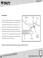
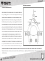
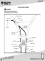
Bicycle Owner’s Manual
CONGRATULATIONS ON THE PURCHASE OF YOUR NEW BIKE! OUR SERVICE
DEPARTMENT IS DEDICATED TO MAKING SURE THAT YOU GET THE MOST
ENJOYMENT POSSIBLE FROM OUR PRODUCTS.
For questions regarding assembly, operation
or warranty please feel free to contact our
Service Representatives
by calling: (888) 909-3652
or
e-mailing [email protected]
DO NOT RETURN THIS ITEM TO THE STORE.PLEASE CONTACT D6 SPORTS
FOR ASSISTANCE WITH ANY PROBLEMS THAT YOU HAVE
01
WWW.SHAUNWHITESUPPLYCO.COM
INTRODUCTION
INTRODUCTION 03 - 11
Your New Bike, Note to Parents, The BMX Bicycle, Safety Checklist, Riding Safely, Helmets
ASSEMBLY 12 - 35
Tools Required, Getting Started, Front Wheel Assembly, Handlebar and Stem Assembly,
Seat Installation, Pedal and Crank Assembly, Brake Set Up, Training Wheel Installation,
Peg Installation
BICYCLE CARE 36 - 52
Maintenance, Storage, Security, Recommended Tools, Handlebar and Stem Information,
Headset Information, Brake Information, Seat and Seatpost Information, Wheel and Tire
Information, Pedal and Crank Information
TROUBLESHOOTING53 - 54
Drivetrain Problems, Brake Problems, Wheel Problems
IMPORTANT INFORMATION55 - 56
Brakes, Tires and Tubes
WARRANTY57 –58
02
INDEX
WWW.SHAUNWHITESUPPLYCO.COM
ALL OF THE ORIGINAL PARTS ON THIS BICYCLE ARE COMPATIBLE WITH YOUR FRAME. CERTAIN
AFTERMARKET PARTS OR COMPONENTS MAY NOT BE COMPATIBLE WITH YOUR BICYCLE OR FRAME.
PLEASE CONSULT YOUR LOCAL BIKE SHOP BEFORE INSTALLING ANY NON-FACTORY SPECIFIED
PRODUCT TO YOUR BICYCLE. USE OF ANY COMPONENT THAT IS NON-FACTORY SPECIFIED COULD
RESULT IN DAMAGE TO THE BICYCLE. THIS DAMAGE WILL NOT BE COVERED UNDER WARRANTY.
MORE IMPORTANTLY, IT COULD CAUSE YOU TO LOSE CONTROL OF THE BICYCLE AND FALL, WHICH
COULD CAUSE SERIOUS INJURY TO THE RIDER.
03
N
IO
T
C
U
D
O
R
T
IN
WWW.SHAUNWHITESUPPLYCO.COM
OWNER’S MANUAL FOR BMX BICYCLES
THIS MANUAL CONTAINS IMPORTANT SAFETY, PERFORMANCE AND MAINTENANCE INFORMATION. READ THE
MANUAL AND ALL WARNINGS BEFORE TAKING YOUR FIRST RIDE ON YOUR NEW BICYCLE, AND REFER TO THE
MANUAL FOR FUTURE REFERENCE.
UNSAFE OR IMPROPER USE OF THE BICYCLE BY FAILING TO READ AND FOLLOW ALL OF THE SAFETY,
PERFORMANCE AND MAINTENANCE REQUIREMENTS AND WARNINGS COULD RESULT IN SERIOUS INJURY OR
DEATH. WEAR A HELMET EVERY TIME YOU RIDE YOUR BICYCLE, AND ALWAYS RIDE IN A SAFE AND CAUTIOUS
MANNER.
04
N
IO
T
C
U
D
O
R
T
IN
WWW.SHAUNWHITESUPPLYCO.COM
INTRODUCTION
CONGRATULATIONS ON THE PURCHASE OF YOUR NEW BICYCLE.
THIS MANUAL IS DESIGNED TO PROVIDE INFORMATION ABOUT THE SAFE OPERATION AND MAINTENANCE OF
YOU NEW BICYCLE. PLEASE READ THIS MANUAL THOROUGHLY BEFORE RIDING YOUR BICYCLE. THE SERIAL
NUMBER FOR YOUR BICYCLE IS LOCATED ON THE BOTTOM BRACKET SHELL OF THE FRAME. PLEASE RECORD
THE SERIAL NUMBER BELOW IN CASE YOUR BICYCLE IS EVER LOST OR STOLEN. YOU MIGHT WANT TO
REGISTER THE SERIAL NUMBER WITH YOUR LOCAL POLICE DEPARTMENT AS WELL. PLEASE KEEP YOUR
SALES RECEIPT AS PROOF OF PURCHASE OF THE BICYCLE.
MODEL NAME _____________________________
SERIAL NUMBER ___________________________
COLOR ___________________________________
DATE OF PURCHASE ________________________
PLACE OF PURCHASE _______________________
05
E
K
I
B
W
E
N
R
U
O
Y
WWW.SHAUNWHITESUPPLYCO.COM
INTRODUCTION
NOTE TO PARENTS
UNFORTUNATELY, MANY BICYCLE ACCIDENTS INVOLVE CHILDREN.
AS A PARENT OR LEGAL GUARDIAN, YOU ARE RESPONSIBLE FOR THE SAFETY OF YOUR CHILD. PLEASE MAKE SURE
THAT THE BICYCLE YOUR CHILD IS RIDING HAS BEEN PROPERLY ADJUSTED AND FITS YOUR CHILD AND IS IN SAFE
OPERATING CONDITION.
IT IS ALSO IMPORTANT THAT YOUR CHILD UNDERSTANDS AND FOLLOWS THE LOCAL TRAFFIC LAWS, AND RIDES IN A
SAFE MANNER. AS A PARENT/GUARDIAN, YOU SHOULD READ THIS MANUAL BEFORE ALLOWING YOUR CHILD TO RIDE
THEIR NEW BIKE. PLEASE MAKE SURE THAT YOUR CHILD WEARS AN APPROVED HELMET EVERY TIME THEY RIDE
THEIR BICYCLE.
06
ENTS
R
A
P
O
T
E
T
O
N
WWW.SHAUNWHITESUPPLYCO.COM
INTRODUCTION
BASIC BICYCLE PARTS
07
YCLE
C
Y
B
X
M
B
E
H
T
WWW.SHAUNWHITESUPPLYCO.COM
INTRODUCTION
SAFETY CHECKLIST TO BE PERFORMED PRIOR TO EVERY BICYCLE RIDE
1.) Brakes
• Make sure that the front and rear brakes work properly
• Make sure that the brake pads are in good condition, and contact to the rim correctly
• Make sure that the brake cables are in good condition and do not look worn out
• Make sure that the brake levers are securely adjusted on the handlebars
2.) Wheels and Tires
• Make sure that the tires are properly inflated to the limit listed on the side of the tire
• Make sure that the tires tread appear to be in good condition and are not worn out
• Make sure that the rims are straight, and do not have any wobbles or hops
• Make sure that the spokes are tensioned correctly, and that there are no spokes broken
• Check to make sure that the wheels are seated correctly in the fork and in the frame
• Make sure that the axle nuts are tight
08
KLIST
C
E
H
C
Y
T
E
F
A
S
WWW.SHAUNWHITESUPPLYCO.COM
INTRODUCTION
3.) Steering
• Make sure that the handlebars and stem are correctly adjusted and tightened
• Make sure that the handlebars are in the correct position in regards to the fork
• Check to see if the headset is adjusted properly, and the steering is not hindered at all
4.) Chain
• Make sure that the chain is lubricated, clean, and works smoothly
5.) Seat/Seatpost
• Make sure that the seat is firmly attached to the seatpost, and is not loose
• Make sure the seatpost height is adjusted correctly and not above the limit line for height
6.) Cranks and Pedals
• Make sure that the cranks are securely tightened and are not loose or bent
• Make sure that the pedals are securely tightened to the cranks
7.) Frame and Fork
• Make sure that there are no cracks on the frame, especially on or around the welds
• Make sure that the frame and fork are not bent or broken
09
KLIST
C
E
H
C
Y
T
E
F
A
S
WWW.SHAUNWHITESUPPLYCO.COM
INTRODUCTION
RIDING SAFELY/GENERAL RULES
ALWAYS WEAR A CERTIFIED HELMET
When riding always obey the same motor laws as other vehicles- give way to pedestrians, stop at all red lights and stop signs,
ride with the flow of traffic, obey speed limits, etc..
Use correct hand signals to indicate turning or stopping
Look ahead. Avoid bumps, potholes, gravel, wet roads, oil, drains, and other obstacles in the road
Walk your bike across train tracks after you have checked to make sure it is safe
Do not carry passengers on your bike- it is unsafe and illegal
Ride smart
10
HELMETS
WWW.SHAUNWHITESUPPLYCO.COM
INTRODUCTION
RULES FOR CHILDREN
• Always wear a properly fitted helmet
• Do not ride in driveways or out in the road
• Do not ride on busy streets
• Do not ride in wet weather
• Do not ride at night
• Obey all traffic laws
• Use caution when entering intersections- make sure that it is clear before you proceed
• Maintain safe speeds when riding down hills
• Never take your hands off the handlebars, or your feet off the pedals when riding.
THE CONSUMER PRODUCT SAFETY COMISSION ADVISES THAT RIDING SMALL DIAMETER WHEEL
BICYCLES AT HIGH SPEED CAN LEAD TO INSTABILITY AND RECOMMENDS AGAINSTDOING SO.
CHILDREN SHOULD BE MADE AWARE OF ALL POSSIBLE RIDING HAZARDS PRIOR TO RIDING THEIR
BICYCLE.
11
HELMETS
WWW.SHAUNWHITESUPPLYCO.COM
ASSEMBLY
SINGLE SPEED AND BMX Includes:
• 12” BMX bikes
• 16” BMX bikes
• 18” BMX bikes
• 20” BMX bikes
Assembly is the same for boys and girls bikes.
Foreword:
Assembling a bicycle is an important responsibility. Proper assembly not only gives the rider more enjoyment of the bicycle,
it also offers an important measure of safety.
12
ORD
W
E
R
O
F
D
N
A
BIKE SIZE
WWW.SHAUNWHITESUPPLYCO.COM
ASSEMBLY
TOOLS REQUIRED:
1.) 4mm, 5mm, 6mm and 8mm Allen key wrenches
2.) An adjustable size wrench
3.) Standard flat head screwdriver
4.) Standard Phillips head screwdriver
5.) An open end 15mm box wrench
6.) Adjustable pliers that have cable cutting ability
7.) A tire pump
13
ED
IR
U
Q
E
R
S
L
O
O
T
WWW.SHAUNWHITESUPPLYCO.COM
ASSEMBLY
GETTING STARTED
Open the carton from the top and remove the bicycle. Remove the straps and protective wrapping from the bicycle.
Inspect the bicycle and all accessories and parts for possible shortages. It is recommended that the threads and all
moving parts in the parts package be lubricated prior to installation. Do not discard packing materials until assembly
is complete to ensure that no required parts are accidentally discarded. Assemble your bicycle following the steps
that pertain to your model.
NOTE: Your bicycle may be equipped with different style components than the ones illustrated.
14
TED
R
A
T
S
G
IN
T
T
E
G
WWW.SHAUNWHITESUPPLYCO.COM
ASSEMBLY
BOX CONTENT
15
T
BOX CONTEN
WWW.SHAUNWHITESUPPLYCO.COM
ASSEMBLY
REMOVING AND INSTALLING BOLT ON WHEELS
A.) Removing a Bolt-On Front Wheel
1.) Open up the brake shoes.
2.) Loosen the axle nuts on the wheel.
3.) Unfasten the safety retention washers/hooks.
4.) Lift the front end of the bike a few inches off the ground and tap downward on the tire.
B.)
Installing a Bolt-On Front Wheel
1.) With the fork facing forward, insert the wheel between the fork legs so that the axle sits firmly inside of the dropouts/axle
slots on the fork legs. The axle nuts and axle washers should both be on the outside of the dropout. If there is a secondary
16
safety/retention system on thewheel, engage it at this time.
2.) While pushing the wheel firmly up into the fork dropouts, and at the same time centering the wheel inside of the fork legs, tighten the axle nuts as tight as you can.
3.) Lift the front wheel off the ground and spin it to make sure that it is centered and clears the brakes on bikes with front brakes.
T
N
E
T
N
O
C
X
O
B
WWW.SHAUNWHITESUPPLYCO.COM
ASSEMBLY
FRONTWHEEL
1. Make sure the brakes are loose enough to allow the wheel to pass through the brake pads easily.
2. Place wheel into fork drop outs.
3. Install retaining washers with raised lip pointed towards the fork, and insert into the small hole
of the fork blade.
4. Install axle nut and tighten. Make sure the wheel is centered between the fork blades.
5. Spin the wheel to make sure that it is centered and clears the brake shoes. Tighten the brakes
if necessary.
6. Turn the bicycle upright using the kickstand to support it.
WARNING
It is very important to check the front wheel connection to the bicycle. Failure to properly tighten
may cause the front wheel to dislodge causing serious injury or death.
LY
17
SEMB
S
A
L
E
E
H
W
T
FRON
WWW.SHAUNWHITESUPPLYCO.COM
ASSEMBLY
FRONT WHEEL ASSEMBLY
LY
18
SEMB
S
A
L
E
E
H
W
T
FRON
WWW.SHAUNWHITESUPPLYCO.COM
ASSEMBLY
C.) Removing a Bolt-On Rear Wheel
1.) Open/undo the rear brake.
2.) Loosen the axle nuts on the wheel.
3.) Slide the wheel forward in the axle slot and while the chain has some slack to it, remove the chain from the
freewheel/cassette.
4.) Pull the rear wheel out of the frame.
D.) Installing a Bolt-On Rear Wheel
1.) Insert the rear wheel all the way up in the axle slot of the frame.
2.) Place the chain on the freewheel/cassette and chainring/sprocket.
3.) Pull the rear wheel back so the chain is properly tensioned.
4.) While pulling the rear wheel back, hold the wheel so that it is centered and tighten the axle nuts as tight as you can.
5.) Close/re-engage the rear brake
6.) Lift the rear wheel off the ground and spin the wheel to make sure that it is centered and clears the brake and frame.
MBLY
19
SSE
HANDLEBAR A
WWW.SHAUNWHITESUPPLYCO.COM
ASSEMBLY
HANDLEBAR ASSEMBLY
Most of our bikes are equipped with a “quill” stem (see illustration).
To assemble the handlebars remove the protective cap from the
wedge end of the stem bolt and loosen the bolt using the 6 mm
Allen key. Some models may use a 13 mm hexagonal bolt instead
of an Allen key bolt. Place the handlebar stem into the top of the
steer tube which is the top end of the fork that has been inserted
into the head tube at the factory, ensuring that all cables are free
of tangles. Tighten the stem bolt observing the Minimum Insertion
Mark and checking that the forks and the handlebars are facing
forward. After the stem bolt is tested tight (see Important Note
on the next page), adjust handlebars to correct position. After
the handlebar stem has been fitted into the steer tube that is the top
end of the fork and the two pieces made firm with in the head tube
the action of a stem bolt upon the wedge nut binds with the inside of the steer tube to form a solid steering
column into the steer tube that is the top end of the fork and the two pieces made firm with in the head tube the
action of a stem bolt upon the wedge nut binds with the inside of the steer tube to form a solid steering column.
MBLY
20
SSE
A
R
A
B
E
L
D
N
A
H
WWW.SHAUNWHITESUPPLYCO.COM
ASSEMBLY
IMPORTANT NOTE:
Test the security of the handlebar stem within the steer tube of the front fork by clamping the front wheel
between your knees and trying to move the handball and/or stem from side to side. The handlebar should
not move independent from the front wheel when applying pressure.
You can adjust the handlebar height a bit by adjusting stem height. A quill stem has an etched or stamped mark on its shaft which
designates the stem’s “Minimum Insertion” or “Maximum Extension”. This mark must not be visible above the headset. There are
different styles of handlebar clamps, but all attach to the bicycle with a stem bolt and wedge nut. Typical of the BMX bicycle is the
four bolt configuration shown above. When tightening the four face plate bolts follow the pattern in the illustration above. All of the
bolts should have equal torque, and if you look at the stem from the side of the bike the gap between the face plate and the stem in
front of the handlebar and behind the handlebar should be the same distance.
MBLY
21
SSE
A
R
A
B
E
L
D
N
A
H
WWW.SHAUNWHITESUPPLYCO.COM
ASSEMBLY
SEAT ASSEMBLY
Loosen nut on the seat clamp and add 3 or 4 drops of oil onto the
threads of the bolt. Place the smaller end of the seatpost into the
seat clamp until it stops with the bolt to the rear of the seatpost.
Thread the nut on the seat clamp loosely. Insert the larger end of
the seatpost into the seat tube of the bicycle frame observing the
Minimum Insertion Mark on the seatpost. Position the top surface
of the seat parallel with the ground. The serrations on the seat
clamp must mesh completely with the seat frame serrations, push
the front of the seat up and down to align the serrations. Securely
tighten the seat clamp. Securely tighten the bolts on the seatpost
clamp. It is a good idea to use some type of lithium grease on the
inside of the frame where the seatpost is inserted to keep the
seatpost from seizing inside of the frame over time.
22
LY
B
M
E
S
S
A
T
A
E
S
WWW.SHAUNWHITESUPPLYCO.COM
ASSEMBLY
PEDALS AND CRANK SET ASSEMBLY
Check for the right (R, red) sticker and left (L, green) sticker on each
pedal and crank arm. Match the appropriate pedal to each crank
(right to right and left to left) for assembly. Start each pedal spindle
by hand to avoid stripping the threads. Tighten with a 15 mm narrow
open ended wrench so that the shoulder of the pedal spindle is
securely tightened against the crank arm. Note that the right hand
pedal attaches to the chainwheel side crank arm with a right-hand
(clockwise) thread. The left pedal attaches to the other crank arm
and has a left-hand (counterclockwise) thread. It is very important
that you check the crank set for correct adjustment and tightness
before riding your bicycle.
WARNING
Attachment of an incorrect pedal into a crank arm will cause irreparable damage. Unless the shoulder of the pedal spindle is tight to the
face of the crank arm, the pedal may back out causing serious injury or death. Make it tight so the shoulder is in complete contact with
the surface of the crank arm. Before your first ride, please check to ensure your pedals are attached correctly.
BLY
23
SSEM
A
K
N
A
R
C
D
N
PEDALS A
WWW.SHAUNWHITESUPPLYCO.COM
ASSEMBLY
HAND BRAKE
Determine which type of brake your bike is equipped with and refer
to the appropriate assembly instructions. For more information on
brake adjustment and maintenance, refer to pages 42-53. It is
important to become familiar with the use of hand brakes. When
properly adjusted, hand brakes are an efficient braking system.
Keep the rim and brake shoes clean and free from wax, lubricants
and dirt at all times. It is recommended that when using the cable
adjusting barrel, the corresponding slots in the brake lever, cable
adjusting barrel and locknut not be aligned.
Keep brakes properly adjusted and in good working condition at all times.
24
LY
B
M
E
S
S
A
E
K
A
HAND BR
WWW.SHAUNWHITESUPPLYCO.COM
ASSEMBLY
SIDE PULL BRAKE ASSEMBLY
SIDE PULL BRAKE
Loosen the cable anchor nut and thread the brake cable through it.
Tighten the nut by hand until it holds the cable in place. Squeeze the
brake arms together against the rim of the wheel. Loosen the nuts
on the brakes shoes and turn until they match the angle of the rim.
Tighten the nuts securely. Loosen the cable anchor nut and squeeze
both brake arms together so that both brake shoes are in contact
with the rim, pull all the slack out of the brake cable, and securely
tighten the cable anchor nut. Spin the wheel, the brake shoes should
not contact the rim at any point and should be an equal distance
from the rim on both sides. Make sure all nuts and bolts are securely
tightened. Test the brake levers 20-25 times to take care of any initial cable stretch. Be sure to tightly secure the brake fixing nut behind
the fork and on the bicycle frame.
BLY
25
M
E
S
S
A
E
K
A
R
B
SIDE PULL
WWW.SHAUNWHITESUPPLYCO.COM
ASSEMBLY
U-BRAKE ASSEMBLY
U-BRAKE INSTRUCTIONS
Adjust the pads of the U-brake using a 10 mm wrench. Make sure
the pad is hitting the rim and not the tire. Ideally the front of the pad
should hit the rim approximately 1 mm before the rear pad. Next,
tighten the Cable Carrier to the brake cable approximately 20 mm
from the brake arms when they are closed against the rim. Attach
the Straddle cable to the carrier. Hook cable end into the brake slot,
pull excess straddle cable through the cable anchor and tighten the
cable anchor. For brake adjustments, use a 13 mm box end wrench
and a 5 mm Allen wrench and loosen the 5 mm Allen bolt. For the
nondrive side (left), turn the spring tension nut with the 13 mm
wrench and tighten the 5 mm Allen bolt. The tension on each side
should be achieved, hold the tension nut with the 13 mm wrench
and tighten the 5 mm Allen bolt. The tension on each side should
be equal so that the brake arms move the same distance when the
brake is activated. U-brakes installed on the front fork of a bicycle
are generally slightly different than that pictured on the left in that they will not have a cable carrier, straddle cable or hook cable end.
Rather, front U-brakes will have a cable anchor at the end of the brake arm. Adjustment for the front brakes is otherwise similar to that
described above.
26
LY
B
M
E
S
S
A
E
K
A
U-BR
WWW.SHAUNWHITESUPPLYCO.COM
ASSEMBLY
CHECK YOUR BRAKES
Press each brake lever to make sure that there is no binding and that the brake pads are hard enough on the rims to stop the bike.
The brake pads should be adjusted so they are 1 mm - 2 mm away from the rim when the brakes are not applied. Brake pads should
be centered on the rim and the rear portion of each brake pad should be about 0.5 - 1.0 mm farther from the rim than the front portion
of brake pad.
WARNING
Do not ride the bicycle until the brakes are functioning properly. To test, apply the brakes while trying to push the bike forward to make
sure they will stop the bicycle.
27
G
IN
N
R
A
W
P
U
T
BRAKE SE
WWW.SHAUNWHITESUPPLYCO.COM
ASSEMBLY
ROTOR ASSEMBLY DIAGRAM
28
BLY
M
E
S
S
A
R
O
T
O
R
WWW.SHAUNWHITESUPPLYCO.COM
ASSEMBLY
Rotor Assembly
Some freestyle BMX bicycles come equipped with a detangler system that will allow the handlebar to spin 360-degrees without
binding the brake cables. It is very important that this system is adjusted correctly.
Upper Cable
1.) First connect the barrel end of the upper cable to the rear brake lever. Make sure that the long cable casing is on top of the
short cable casing; otherwise the upper cable will have a twist in it.
2.) Route the upper cable through the handlebars (below the crossbar) with the short cable casing on the same side as the rear
brake lever.
3.) Connect the upper cable to the upper plate by passing the football ends of the upper cable through the threaded holes in the
upper plate and connecting them to the bearing.
4.) Screw the adjusting barrels into the upper plate. Do not tighten the locknuts at this time.
29
BLY
ROTO
SSEM
A
E
K
A
R
B
R
A
E
R AND R
WWW.SHAUNWHITESUPPLYCO.COM
ASSEMBLY
Lower Cable
1.) Slide the cable casing the cable guide on the frame
2.) Connect the lower cable to the lower plate by passing the football ends of the lower cable through the threaded holes
in the lower plate and connecting them to the bearing.
3.) Screw the adjusting barrels into the lower plate. Do not tighten the locknuts at this time.
4.) Connect to the rear brake. Do not adjust the rear brake at this time.
NOTE: Check to make sure all eleven cable casing ends on the upper and lower cables are seated
correctly, and that the spring tension of the rear brake is pulling the bearing down.
30
BLY
ROTO
SSEM
A
E
K
A
R
B
R
A
E
R AND R
WWW.SHAUNWHITESUPPLYCO.COM
ASSEMBLY
Rotor Adjustment
1.) Screw the cable adjusters on the rear brake lever and the upper cable all the way in.
2.) Screw the adjusting barrels in the upper plate in (or out) to set the bearing for maximum travel. The bearing should be as far
down as it can go without resting on the lower plate or the adjusting barrels screwed into the lower plate.
3.) Use the adjusting barrels that are screwed into the upper plate to make the bearing parallel to the upper plate. Use a 10mm
wrench to tighten the locknut on the left adjusting barrel of the upper plate. Leave the right side adjusting barrel loose.
4.) Screw the lower cable adjusting barrel into (or our of) the lower plate until they are as close to the bearing as they can get
without touching it.
5.) Screw the cable adjuster on the upper cable splitter out until all slack is removed from the upper cable. Then screw the
cable adjuster out one more turn to raise the bearing and additional 1mm away from the lower adjusting barrels.
CAUTION: Do not screw the cable adjuster on the upper cable splitter out more than 8mm. Use the cable
adjuster on the brake lever if more adjustment is needed.
31
NT
E
M
T
S
U
J
D
A
R
ROTO
WWW.SHAUNWHITESUPPLYCO.COM
ASSEMBLY
6.) Check for bearing flop by placing the handlebars in the normal riding position, then quickly rotate the handlebars back and
forth. Perform the following steps to eliminate bearing flop.
NOTE: the bearing should never be allowed to rest on the lower plate or lower adjusting cables.
a.) screw the lower cable adjusting barrels out of (or into) the lower plate until all bearing is eliminated.
b.) tighten the locknut of the right side adjusting barrel.
c.) rotate the handlebars 180-degrees and recheck for bearing flop.
If there is any bearing flop, use the “loose” adjusting barrels on the upper and lower cables to remove it.
d.) repeat steps (6a) and (6c) until the handlebars can be rotated 360-degrees without any bearing flop.
7.) Finish adjusting the rear brakes.
32
NT
E
M
T
S
U
J
D
A
R
ROTO
WWW.SHAUNWHITESUPPLYCO.COM
ASSEMBLY
TRAINING WHEEL ASSEMBLY
TRAINING WHEEL ASSEMBLY
1. Position frame clip over rear axle nut with tab located in frame axle slot.
2. Locate brace over frame clip and secure with nut using 15 mm or
adjustable wrench.
3. The elongated hole on the brace allows for raising or lowering the training
wheels to the proper height. Once proper height is determined, secure
brace in position by tightening nut securely.
33
LY
B
M
E
S
S
A
L
E
E
TRAINING WH
WWW.SHAUNWHITESUPPLYCO.COM
ASSEMBLY
PEG ASSEMBLY
34
Step 1 - Remove all protective packaging from the axle
so the axle nut is visible
Step 2 - Using a 15mm socket wrench with an extension,
loosen the axle nut by turning in a counter-clockwise
direction
Step 3 - After the axle nut has been removed, place the
axle nut in the 15mm socket wrench so the flange of the
axle nut is facing upward
Step 4 - Place the large open end of the peg over the axle
nut and 15mm socket wrench
Y
L
B
M
E
S
S
A
G
E
P
WWW.SHAUNWHITESUPPLYCO.COM
ASSEMBLY
PEG ASSEMBLY
Step 5 - Lower the peg all of the way down onto the axle
nut and 15mm socket wrench
Step 6 - Place the small open end of the peg onto the
axle of the wheel while holding the 15mm socket wrench
and peg together so there is no movement between the two
Step 7 - Tighten the peg onto the axle by turning the
15mm socket wrench in a clockwise direction. 35
Y
L
B
M
E
S
S
A
G
E
P
WWW.SHAUNWHITESUPPLYCO.COM
BICYCLE CARE
Basic Maintenance
To clean your bicycle you can wipe it down with a damp cloth or rag. You may also spray a mild cleaner (Simple Green, Windex, etc.)
on the bike and wipe it off with a clean rag. Do not spray your bicycle with a power washer or hose- this may damage some of the
bearings on your bicycle. Your local bike shop should have some cleaning supplies to help you keep your bicycle looking like new.
If the paint on the frame has become chipped you can use a similar color nail polish or touch up paint to prevent rust. Most hobby
stores have a good selection of touch up paints.
Regular cleaning and lubrication will extend the life of your bicycle. It is recommended that you take the bicycle to your local bike
shop for routine maintenance and service.
Correct routine maintenance of your new bike will keep it running smoothly and help the components last longer. The more you ride
your bicycle, the more maintenance it is going to require. The following is a guide on how often you should perform certain routine
maintenance, and what should be done…
36
NCE
A
N
E
T
IN
A
M
BASIC
WWW.SHAUNWHITESUPPLYCO.COM
BICYCLE CARE
SCHEDULE 1- LUBRICATION
Every Month
Lube the chain with chain lube (Tri- Flow, Pedro’s, Finish Line- DO NOT USE WD-40)
Lube the brake pivots with chain lube
Lube the pivots on the brake lever with chain lube
Every Six Months
Lube the inner wire of the brake cable
Lube the freewheel
Once a Year
37
Grease the seat tube of the frame (where the seat post goes in) with synthetic grease
Grease the pedal threads and bearing with synthetic grease
Grease the bottom bracket threads on the frame with synthetic grease
Grease the bottom bracket bearings (non sealed) with synthetic grease
Grease wheel bearings (non sealed) with synthetic grease
Grease headset bearings (non sealed) with synthetic grease
LUBRICATION
WWW.SHAUNWHITESUPPLYCO.COM
BICYCLE CARE
SCHEDULE 2- SERVICE CHECKLIST
38
Before Every Ride
Weekly
Check tire pressure
Lubrication per Schedule 1
Check brake operation
Check handlebar and stem adjustment
Check wheels for loose spokes and/or wobble
Check seat and seatpost adjustment
Check wheel axle nuts
Inspect chain and freewheel/cassette for wear
Inspect tires for wear and damage
Check headset adjustment
Check frame and fork for cracks
Check brake adjustment
Check brake pads for wear
Make sure all bolts and axle nuts are tightened to specification
Monthly
Yearly
Lubrication per Schedule 1
Lubrication per Schedule 1
Check all weekly Service items
Routine service at local bike shop
Inspect cranks and sprocket
T
IS
L
K
C
E
H
C
E
IC
SERV
WWW.SHAUNWHITESUPPLYCO.COM
BICYCLE CARE
Storage
Keep your bicycle in a covered and dry area where it will not be exposed to the weather and sun. Sunlight can damage the grips and
tires on a bicycle, as well as fade the color of the paint. The warranty on this bike does not cover paint damage, corrosion, rust, or theft.
Always store your bicycle under shelter, and do not leave it exposed to rain or other damaging weather conditions. If you live near a
beach be advised that the salt in the air is very corrosive to some of the parts on your bicycle. You will need to take extra care to make
sure you clean and/or wipe the bike down frequently to avoid damage.
Security
Make sure that you record the bicycle’s serial number, model, color, and place of purchase. Register the bike with your local police
department. Invest in a high quality lock as well. Always lock your bicycle
to a heavy/immovable object if it is left unattended.
39
Y
IT
R
U
C
E
S
D
N
A
STORAGE
WWW.SHAUNWHITESUPPLYCO.COM
BICYCLE CARE
Recommended Tools for Basic Maintenance
- Allen wrenches in 2mm/3mm/4mm/5mm/6mm/8mm sizes
- Open end wrenches in 9mm/10mm/14mm/15mm/19mm sizes
- Phillips head screwdriver
- Plastic tire levers
- Spare inner tube
- Floor pump with pressure gauge
G
40
UNIN
T
D
N
A
E
C
N
A
TEN
IN
A
M
E
L
C
Y
IC
B
WWW.SHAUNWHITESUPPLYCO.COM
BICYCLE CARE
Handlebars and Stem
Handlebars come in all sorts of shapes and sizes. Handlebar adjustment (in regards to the angle) depends mostly on the rider’s
personal preference. Most rider’s prefer to have the handlebars parallel to the fork legs (if you are looking at the bike from the side).
Some rider’s prefer to have their bars a little more forward, some riders prefer to have their bars a little more back. The main thing is
that the rider is comfortable with the position of the handlebars, and can maneuver the bike easily.
There are two types of Stems on BMX bikes- Quill Stems and Direct Mount Stems (for threadless forks). Quill Stems have a shaft the
is inserted down into the Head Tube of the frame, and then held into place by tightening a binder bolt that is connected to an expanding wedge that binds with the inside of the fork steer tube. The height of the stem and handlebar can be adjusted by raising or lowering the stem. There is a minimum insertion mark approximately 70mm up from the bottom of the shaft on the stem. There are usually
notch marks with the words “Maximum Height” or “Minimum Insertion” written on the stem. DO NOT RAISE THE STEM HIGHER
THAN THAT- SERIOUS INJURY MAY RESULT. Also, do not over tighten any of the stem bolts or headset compression bolts
that might cause damage to the bicycle and injury to the rider.
Direct Mount Stems slide over the steer tube of the fork and are held in place by tightening bolts on the side of the stem that clamp
the stem onto the fork. The height on a Direct Mount stem is adjusted by moving headset spacers above or below the stem on the
steer tube of the fork. Make sure that you do not over tighten any of the bolts on a Direct Mount Stem, as they might break or strip the
threads out of the stem body. To check the tightness of the handlebars and stem, stand in front of the bike and place the front wheel
between your knees while facing the bike. You should grab the grips of the handlebars with your hands and try to turn the handlebars
to the side and try to move them forward andbackwards. If the Stem is adjusted correctly the handlebars will not move when pressure
is applied to them. If you are unsure if the handlebars and stem are adjusted correctly, please consult your local bike shop.
41
EM
T
S
D
N
A
S
R
A
HANDLEB
WWW.SHAUNWHITESUPPLYCO.COM
BICYCLE CARE
HEADSET
The headset is the bearings that allow the rider to steer the bicycle. The headset bearing adjustment is something that should be
checked every month. If the headset is not adjusted correctly, it can damage the bicycle and cause the rider to fall.Headset bearing
adjustment requires special tools and training. We strongly recommend that you have a trained mechanic at your local bike shop adjust the headset on your bicycle. You can check to make sure that the headset on your bicycle is adjusted correctly by turning the handlebars 90 degrees to the side while the bike is on the ground, and then rolling the bike forward and backward a little bit. You should
not feel any movement or looseness in the headset when you are doing this. You can also damage the bicycle and possibly cause the
rider to fall by having the headset over tightened. Again- we strongly recommend having a trained mechanic adjust the headset on
your bicycle.
42
HEADSET
WWW.SHAUNWHITESUPPLYCO.COM
BICYCLE CARE
BRAKE CABLE AND BRAKE CABLE HOUSING
Before every ride check to make sure that there are no kinks in the brake cable or brake cable housing, and make
sure that the brake cable/inner wire is not frayed anywhere. Also make sure that the brake cable housing is securely
attached to the brake lever, the cable stops on the frame of the bicycle, and the brake itself. The brake lever should
not require much pressure when it is squeezed. If the brake lever becomes difficult to squeeze, it might be time to
replace the brake cable on the bicycle.
DO NOT RIDE THE BICYCLE IF THE BRAKES ARE NOT WORKING CORRECTLY!
43
G
IN
S
U
O
H
D
N
A
BRAKE CABLE
WWW.SHAUNWHITESUPPLYCO.COM
BICYCLE CARE
SEAT AND SEATPOST
The seat clamp bolt(s) and seat post clamp bolts should be checked for tightness at least once a month. The seat will either have two
14mm nuts on the side of the seat guts which can be tightened with a 14mm box wrench, or a 5mm or 6mm allen bolt on the seatpost
that can be tightened with the appropriate sized allen wrench. The seat should not move up or down when pressure is applied to it.
The seatpost also has a “Maximum Height” or “Minimum Insertion” marking on it. The seatpost must be inserted into the frame so that
the Max Height/Minimum Insertion mark cannot be seen. Failure to do this might result in loss of control and injury to the rider.
44
ST
O
P
T
A
E
S
D
N
A
SEAT
WWW.SHAUNWHITESUPPLYCO.COM
BICYCLE CARE
WHEELS AND TIRES
Wheel Inspection
It is most important that wheels are kept in top condition. Properly maintaining your bicycles wheels will help braking performance
and stability when riding. Be aware of the following potential problems:
Dirty or Greasy rims:
Caution: these can render your brakes ineffective. Do not clean them with oily or greasy materials. When cleaning, use a clean rag or
wash with soapy water, rinse and air dry. Do not ride the bicycle while the rims are wet. When lubricating your bicycle, do not get oil
on the rim braking surfaces.
Wheels not straight:
Loft each wheel off the ground and spin them to see if they are crooked or out of true. If the wheels are not straight, they will need to
be adjusted. This is difficult and is best left to a bicycle specialist.
S
45
TIRE
D
N
A
S
L
E
E
H
W
WWW.SHAUNWHITESUPPLYCO.COM
BICYCLE CARE
Broken or loose spokes:
Check that all spokes are tensioned correctly and that no spokes are missing or damaged.
Caution: such damage can result in severe instability and possibly an accident if not corrected.
Again, spoke repairs are best handled by a bicycle specialist.
Loose hub bearings:
Lift each wheel off the ground and try to move the wheel from side to side.
Caution: if there is movement between the axle and the hub, do not ride the bicycle. Adjustment is required.
Axle nuts:
Check that these are tight before each ride.
S
46
TIRE
D
N
A
S
L
E
E
H
W
WWW.SHAUNWHITESUPPLYCO.COM
BICYCLE CARE
Tire Inspection
Tires must be maintained properly to ensure road holding and stability. Check the following areas:
Inflation: Ensure tires are inflated to the pressure indicated on the tires sidewall. It is better to use a tire gauge and a floor pump than the air compressor at a service station.
Caution: if inflating tires with a service station air compressor, take care that sudden over inflation does
not cause tire to blow out. This can severely damage the tire and/or bicycle rim.
Tread: heck that the tread shows no signs of excessive wear or flat spots, and that there are no cuts or other damage.
Caution: excessive worn or damaged tires should be replaced.
Recommended Tire Pressure: Please follow the tire manufacturers guidelines which can be found molded into the sidewall of
the bicycle tires.
S
47
TIRE
D
N
A
S
L
E
E
H
W
WWW.SHAUNWHITESUPPLYCO.COM
BICYCLE CARE
BRAKES
The correct adjustment and operation of your bicycle’s brakes is extremely important for safe operation.
Brakes should be checked for effective operation before every ride. Frequent checking of adjustment is necessary as the control cables
will stretch and the brake pads will become worn with use.
DO NOT RIDE YOUR BICYCLE IF THE BRAKES ARE NOT WORKING PROPERLY.
There are numerous types of brake systems and common use on today’s modern bicycles:
Side Pull Calipers and U-Brakes - Each utilize a handlebar mounted brake lever which controls a cable to operate the brake.
Side pull brakes are mounted to the frame or fork via a single pivot point. Linear and U-Brakes use two brake pivot arms, each mounted
on separate pivots on either side of the frame/fork.
Brake Inspection
Brake levers should be checked for tightness at least every three months. They should be set in a comfortable position within easy reach
of the rider’s hand, and must not be able to move on the handlebar. Some brake levers make use of a reach adjustment screw, which
can be altered to the distance between the handlebar grip and the lever, as required. The brake pads should be checked for correct
positioning and tightness before every ride, and the various bolts and nuts at least every three months. Squeeze each brake lever to
make sure they operate freely and that the brake pads press hard enough on the rims to stop the bike. There should be about
1mm-2mm clearance each brake pad and the rim when the brakes are not being applied. The brake pads must be properly centered
for maximum contact with the rim. Replace the brake pads if they over worn so that the grooves or pattern cannot be seen. The brake
cable wires should be checked for kinks, rust, broken strands, or frayed ends. The outer casing should also be checked for kinks,
stretched coils, and other damage. If the cables are damaged, they should be replaced.
48
BRAKES
WWW.SHAUNWHITESUPPLYCO.COM
BICYCLE CARE
Lubrication
The brake lever and brake caliper pivot points should be lubricated with two to three drops of chain lube at least every three months to
ensure smooth operation and to reduce wear. Cables should be greased along their entire length, after removing them from the casings,
at least every six months period. Always grease new cables before fitting.
Adjustment- Side Pull Calipers
Minor brake adjustment can be made via the cable adjusting barrel, usually located at the upper cable arm. To adjust, squeeze the brake
pads against the rim, loosen the lock nut and turn the adjuster. Brake pad clearance should be a maximum 2mm from the rim. When
correct, re-tighten the lock nut. If the pads cannot be set close enough to the rim in this manner, you may have to adjust the cable length.
Screw the barrel adjuster ¾ of the way in, squeeze the pads against the rim, undo the cable anchor bolt and pull the cable through with
pliers. Re-tighten the cable anchor bolt and apply full force to the brake lever to test, then fine tune using the barrel adjuster. If one pad
is closer to the rim than the other pad, loosen the fixing nut at the back of the brake, apply the brake to hold it centered, and re-tighten
the fixing nut. ENSURE THE BRAKE FIXING NUT IS SECURED TIGHTLY. FAILURE TO DO THIS MAY CAUSE THE
BRAKE ASSEMBLY TO DISLODGE FROM THE BICYCLE FRAME OR FORK.
Some brakes have a special mechanism which enables you to set the clearance on either side of the rim using a screwdriver.
Brake pads should finally be adjusted so that the leading edge of the pad makes contact with the rim first. Some brakes have special
curved washers to allow this but on less complex models it will be necessary a little force to the pad and it’s mounting.
49
NT
E
M
T
S
U
J
D
A
S
IPER
L
A
C
L
L
U
P
E
ID
S
WWW.SHAUNWHITESUPPLYCO.COM
BICYCLE CARE
Adjustment: U-Brakes
As with most brake systems, minor adjustments can be made with the barrel adjuster on the brake lever. To adjust, loosen the barrel
adjuster lock nut, and turn the barrel adjuster out counter-clockwise to reduce brake pad clearance and lever pull. To increase brake
pad clearance and lever pull, turn the barrel adjuster in. When adjustment is complete, hold the barrel adjuster in place and turn the
lock ring so that it is tight against the brake lever body. This will lock the adjustment in place. Note that this process should only be
done for very minor brake adjustments. Larger adjustments should be made at either the brake arm pinch bolt or the straddle cable
pinch bolt. To adjust, loosen the brake cable pinch bolt and either pull more cable through or let more cable out, depending on what is
needed. While holding the cable in position, re-tighten that cable pinch bolt. As with any new brake adjustment, compress and release
the brake lever at least ten times to ensure proper brake operation
50
NT
E
M
T
S
U
J
D
A
S
U-BRAKE
WWW.SHAUNWHITESUPPLYCO.COM
BICYCLE CARE
DRIVETRAIN
The drivetrain of a bicycle refers to all parts that transmit power to the rear wheel including the pedals, crankset, chain, and
freewheel/cassette.
PEDALS
Your bicycle comes equipped with BMX platform pedals. Each of the pedals is marked with an “L” and a “R” to indicate
which is the left and which is the right side pedal. To install the left side pedal place the pedal threads into the left crank arm
and turn the pedal counter-clockwise with a 15mm wrench. To install the right side pedal place the pedal threads into the
right crank arm and turn the pedal clockwise with a 15mm wrench. Make sure that the pedals are tight every time you ride.
Do not ride your bike with loose pedals- it will damage the cranks and the pedals and can cause you to fall and be
severely injured.
51
LS
A
D
E
P
D
N
A
IN
DRIVETRA
WWW.SHAUNWHITESUPPLYCO.COM
BICYCLE CARE
CRANKSET
The crankset refers to the crank arms, chainring/sprocket, bottom bracket spindle, and bottom bracket assembly.
There are two types of cranks on BMX bikes - one piece cranks and three piece cranks.
One piece cranks have the crank arms and bottom bracket spindle combined in one piece.
Three piece cranks have the left crank arm, bottom bracket spindle, and right crank arm all separate.
The crank arms on three piece bolt directly onto the bottom bracket spindle. Check to make sure that the cranks are tight before every
ride, and do not ride the bicycle if the cranks are loose or wobble when checked for tightness.
The bottom bracket is the bearings inside of the frame that allow the bicycle to be pedaled. The bearings can be either loose ball or
sealed bearings.
It is very important the bottom bracket bearings be greased thoroughly when they are installed, and should be checked to make sure
that there is sufficient grease in the bottom bracket regularly. Bottom bracket bearing adjustment requires specialized tools and knowledge. It is recommended that you take your bike to a qualified
mechanic at your local bike shop for adjustment and maintenance.
52
CRANKSET
WWW.SHAUNWHITESUPPLYCO.COM
G
TROUBLESHOOTIN
Problem
Chain Slipping - This can be the result of excessively worn teeth on the chainring/sprocket, a worn or stretched chain, or a stiff link
in the chain. Possible solutions for this are replacing the chainring/sprocket, replacing the chain, or lubricating the chain.
Chain Keeps Coming Off - This can be the result of the chainring/sprocket not being straight, the chainring/sprocket being loose,
bent or broken teeth on the chainring/sprocket, or the chain tension is too loose.
Possible solutions for this are straightening or replacing the chainring/sprocket, tightening the chainring/sprocket and
cranks, and tensioning the chain by moving the rear wheel back in the dropouts.
Freewheel Does Not Rotate - This can be the result of the internal mechanism of the freewheel being jammed.
A possible solution to this would be to lubricate the inside of the freewheel. If this does not work replace the freewheel.
Brakes Not Working Effectively - This can be the result of the brake pads being worn down, the brake pads or rims being dirty.
greasy/wet, the brake cables are binding or stretched, the brake lever binding, or the brakes are out of adjustment.
Possible solutions for this are replacing the brake pads, cleaningthe brake pads and rim surface, clean/adjust/replace the
brake cables, adjust the brake levers, or adjust the brakes.
Brakes Squeal/Squeak When Applied - This can be the result of the brake pads being worn down, the brake pads not hitting
the rim correctly, the brake pads being dirty, or the brake arms being loose.
Possible solutions for this are to replace the brake pads, adjust how the brake pads hit the rim, clean the brake pads and rim,
and tighten the mounting bolts on the brakes.
53
PROBLEMS
NS
IO
T
U
L
O
S
E
L
AND POSSIB
WWW.SHAUNWHITESUPPLYCO.COM
G
TROUBLESHOOTIN
Knocking Sound When Applying Brakes - This can be caused by a bulge in the rim or the rim not being straight, the brake
mounting bolts being loose, the brakes being out of adjustment, or the fork being loose.
Possible solutions for this are to take the wheel to a bike shop and have them straighten the wheel, tighten up the brake
mounting bolts, adjust the brakes so that the brake pads contact the rim correctly, and tighten the headset.
Wheel Wobbles - This can be caused by a broken axle, the wheel being out of true (straight), the hub
being loose, the headset binding, or damaged hub bearings. Possible solutions are to replace the axle, have your local bike shop
true (straighten) the wheel, adjust the hub bearings, adjust the headset, or replace the hub bearings.
Steering Not Accurate - This can be caused by the wheels not being lined up correctly in the frame or fork, the headset not being
adjusted correctly, or the frame/fork being bent. Possible solutions for this are to align the wheels correctly in the frame and fork,
and adjust the headset. If you suspect that the frame or fork is bent take your bike to your local bike shop and have them
check to make sure.
DO NOT RIDE THE BICYCLE IF THE FRAME OR FORK ARE BENT.
Frequent Punctures - This can be caused by the inner tube being old or defective, the tire being worn out, the tire not being seated
to the rim correctly, something sharp embedded in the tire, the tire pressure being too low, or a spoke protruding into the tube.
Possible solutions to this are replacing the inner tube, replacing the tire, replacing the tire with the correct sized tire, removing the sharp object from the tire, inflating the tube to the correct air pressure, and filing down the section of spoke that is
sticking out of the spoke nipple.
54
PROBLEMS
NS
IO
T
U
L
O
S
E
L
AND POSSIB
WWW.SHAUNWHITESUPPLYCO.COM
N
RMATIO
IMPORTANT INFO
Important Information
It is important for your enjoyment and safety that you understand how certain things work on your bicycle. Even if you are an experienced bicycle rider, do not make the assumption that all bikes have the same types of parts- this is not always the case. Be sure to
read and understand this section of the manual. If you have any questions, or are unsure about how something on your bike works,
please do not hesitate to speak to a qualified mechanic at your local bike shop.
BRAKES
It is important that you understand how the brakes on your bicycle work. The braking action of a bicycle is the result of friction that it
caused between the brake pads and the rim. To make sure that your brakes will work as well as possible, it is important that you keep
the rims of your bicycle dry and clean. Never use lubricants, polishes, or waxes to clean your rims. Once those materials come in
contact with the brake pads it will greatly reduce the braking on your bicycle. Make sure that your hands can reach and apply pressure (squeeze) to the brake lever. Some brake levers have a reach adjust function that will bring the lever closer to the handlebars.
Please have your local bike shop adjust the reach on the brake lever if necessary. Often times the brakes will need to be readjusted if
the reach adjust function is used. Brakes are designed to control the speed of the bicycle in addition to stopping the bicycle. The more
pressure that is applied to the brake lever, the more the bicycle will slow down. It is important that you do not skid when you are braking. Once the tire starts to skid you lose most of your stopping power and control of the bicycle. The more weight that is placed over
the wheel that is having the brakes applied to it, the less likely the chance that the tire will skid. You should practice slowing and stopping the bicycle before you ride in traffic or crowded areas. Check your brakes before every ride to make sure that they are working
properly, and can provide adequate stopping power.
55
MATION
R
BRAKES INFO
WWW.SHAUNWHITESUPPLYCO.COM
G
TROUBLESHOOTIN
TIRES AND TUBES
Bicycle tires are available in many different sizes and designs. Some tires are designed for street use with a smooth tread that provides
very little rolling resistance. Some tires are designed for off-road use with a knobby tread design to provide more grip in the dirt. And
some tires are designed to be ridden on and off road, and have an enduro style tread pattern. Your bicycle has been equipped with tires
that the manufacturer believed to be the best tire for the type of riding that this bicycle was intended for. Make sure that you consult your
local bike when purchasing new tires for your bicycle- they can explain what tires will fit on the bicycle, and why you might want to use
one style tire as opposed to another style tire. The tire size and pressure rating will be marked on the sidewall of each tire. It is important that you inflate the tire to the proper pressure. WARNING- never inflate the tire beyond the maximum pressure that is marked on the tire’s sidewall. Exceeding
the maximum pressure could blow the tire off the rim, which could cause injury to the rider or people nearby, and damage the tire and rim
beyond repair. The best way to inflate a bicycle tire is with a bicycle floor pump that has a pressure gauge attached to it.
56
TIRES
N
IO
T
A
M
R
O
F
IN
AND TUBES
WWW.SHAUNWHITESUPPLYCO.COM
WARRANTY
WARRANTY
LIMITED WARRANTY
Your bicycle purchase includes the following limited warranty which is in lieu of all other express warranties. This warranty is extended
only to the initial customer that purchased the bicycle.
FRAME WARRANTY
Steel frames are guaranteed against manufacturing defect (defined as a defect in materials or workmanship as delivered with the product) for a period of one year from the date of original purchase. If frame failure should occur due to faulty materials or workmanship during the warranty period, the frame will be replaced with one of equal or greater value. Authorized dealers will initiate a warranty claim for
you. Frames must be returned for inspection at the customer’s expense and please include a copy or the original and dated purchase
receipt.
COMPONENT WARRANTY
All parts excluding normal wear parts are guaranteed against a defect in materials for a period of 90 days from the date of original purchase. If failure of a part should occur during the warranty period, the part will be replaced. Please contact an authorized dealer to
initiate a warranty claim on your behalf. All parts must be returned for inspection at the customer’s expense and be accompanied by a
copy of the original and dated purchase receipt. Normal wear parts include the grips, inner tubes, tires, cables, brake shoes, and seat
covering, and have a limited 30 day warranty. Claims against normal wear parts and missing parts must be made within 30 days of the
purchase of the bicycle. Please contact your local authorized dealer for warranty assistance on components.
57
WARRANTY
WWW.SHAUNWHITESUPPLYCO.COM
WARRANTY
EXCLUSIONS
Any other warranty claim not included in the statements above is void. This especially includes installation, assembly, and disassembly
costs. The limited warranty does not cover paint damage, rust, any modification made to the bicycle, normal wear and tear, improper
assembly or maintenance, and installation of parts or accessories not originally intended or compatible with the bicycle as sold. The
warranty does not apply to damage or failure due to accident, abuse, misuse, neglect or theft. Warranty claims involving these issues
will not be honored.
USEFUL LIFECYCLE
The length of useful lifecycle will vary depending on the type of bike, riding conditions, and care that the bicycle receives. Competition,
dirt jumping, trick riding, skate park riding, trial riding, riding in severe conditions or climate, riding with excessive loads, or any other
non standard use can substantially shorten the useful product lifecycle. Any one of combination of the above may result in an unpredictable failure that will not be covered by this limited warranty. All bicycles and frame sets should be checked periodically by trained
professionals for indications of potential problems, inappropriate use and/or abuse. These are important safety checks and may help
prevent accidents, injury to the rider, and a shortened product lifecycle.
58
WARRANTY
WWW.SHAUNWHITESUPPLYCO.COM
Corporate Office
17277 Ventura Blvd. Suite 204
Encino, California 91316
(888) 909-3652 Phone
(818) 783-1606 Fax
[email protected]
Customer Service 1 (888) 909-3652
WWW.SHAUNWHITESUPPLYCO.COM