1
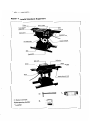
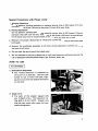
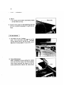
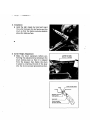
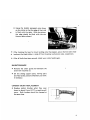
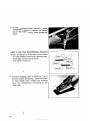
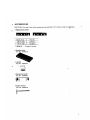
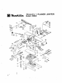
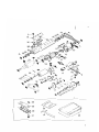
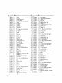
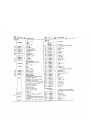
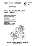
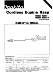
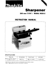
132mm (5%")MODEL 2004
INSTRUCTION MANUAL
MODEL
NO.
width
Auto feed
2004
~
Manual
infeed
No, of
knives
Two on
each feed
'''0°
czkg
depth
132"
3mm
f5-1/4")
f118")
Continuour rating,
Input
-
Output
697
Feed ratelmin.
Table size fW x L )
Fence size
9.7m 131'8ft')
120"
x 410"
(4.3/4")~(15.3/4")
-
Rabbet depth
6mm 1114"l
l2Omm x 8OOmm
1 4 4 4 " ) x 131-1/2"1
500"
x 70"
119-5/8") x (2-3/4")
No load
Overall dimensions
speed
fWx L x HI
8.500
R/min.
x 592"
800mm x 423"
131.1/2") X (16-5/8") x 123.5/16')
ws"$),
SUPPk
4 2 kg
2.5m
(92.6 lbsl
18.2 f t . )
Power
cord
BEFORE CONNECTING YOUR TOOL
TO A POWER SOURCE
Be sure you have read all
GENERAL POWER TOOL SAFETY RULES
GENERAL SAFETY PRECAUTIONS
1. KEEP GUARDS IN PLACE and in working order.
2. REMOVE ADJUSTING KEYS AND WRENCHES. Form habit of checking to see
that keys and adjusting wrenches are removed from tool before turning it on.
3. KEEP WORK AREA CLEAN. Cluttered areas and benches invite accidents.
4. AVOID DANGEROUS ENVIRONMENT. Don't use power tools in damp or wet
locations. Keep work area well lit.
5. KEEP CHILDREN AWAY. All visitors should be kept safe distance from work area.
6. MAKE WORKSHOP KID PROOF - W i t h padlocks, master switch-, or by removing starter keys.
7. DON'T FORCE TOOL. It will do the job better and safer a t the rate for which it
was designed.
8. USE RIGHT TOOL. Don't force tool or attachment to do a job it was not designed
for.
9. WEAR PROPER APPAREL. No loose clothing or jewelry t o get caught in moving
parts. Rubberjoled footwear is recommended for best footing.
10. USE SAFETY GLASSES. Also use face or dust mask if cutting operation i s dusty.
11. SECURE WORK. Use clamps or a vise to hold work when practical. It's safer than
using your hand and it frees both hands to operate tool.
12. DON'T OVERREACH. Keep proper footing and balance a t all times.
13. MAINTAIN TOOLS WITH CARE. Keep tools sharp and clean for best and safest
performance. Follow instructions for lubricating and changing accessories.
14. DISCONNECT TOOLS before servicing; when changing accessories such as cutter
blades.
15. AVOID ACCIDENTAL STARTING. Make sure switch is in off position before
plugging in.
16. USE RECOMMENDED ACCESSORIES. Consult the owner's manual for recommended accessories. The use of improper accessories may cause hazards.
17. NEVER STAND ON TOOL. Serious injury could occur if the tool is tipped or if
the cutting tool i s accidentally contacted.
18. CHECK DAMAGED PARTS. Before further use of the tool, a guard or other part
that i s damaged should be carefully checked to ensure that i s will operate properly
and perform i t s intended function check for alignment of moving parts, binding
of moving parts, breakage of parts, mounting, and any other conditions that may
affect i t s operation. A guard or other part that is damaged should be properly repaired or replaced.
19. PROPER GROUNDING. These tools should be grounded while in use t o protect
the operator from electric shock.
-
PRE LlMlNAR Y I NSTR UCTlONS
Your electric tool i s precision built and manufactured to satisfy the highest standards. For maximum
performance, long tool life, and your safety, follow these instructions carefully.
VOLTAGE WARNING: Before connecting the tool t o a power source (receptacle, outlet, etc.) be
sure the voltage supplied i s the same as that specified on the nameplate of the tool. A power source
with voltage greater than that specified for t h e tool can result in SERIOUS INJURY t o the user - as
well as damage t o the tool. I f in doubt, DO NOT PLUG IN THE TOOL. Using a power source w i t h
voltage less than the nameplate rating i s harmful to the motor.
For all grounded tools with American type plug.
GROUNDING INSTRUCTIONS: This tool should be grounded while in use t o protect t h e operator
from electric shock. The tool is equipped with an approved three-conductor cord and threeprong
grounding-type plug t o f i t the proper grounding-type receptacle. The green (or green and yellow)
conductor in the cord i s the grounding wire. Never connect the green (or green and yellow) wire t o
a live terminal. I f your unit i s for use on less than 150 volts, it has a plug that looks like Fig. "A".
It i t i s for ure on 150-250 volts, i t has a plug that looks like Fig. "D".
An adapter, Fig. "B" and " C ' is available for connecting Fig. " A ' plugs t o two-prong receptacles,
(see Note). The green-colored rigid ear, lug, etc., extending from the adapter must be connected t o
a permanent ground such as t o properly grounded outlet box. N o adapter i s available for Fig. "D"
plugs.
Grounding Blade
FIG. D
Cover' of Grounded Outlet Box
\
NOTE: THE GROUNDING ADAPTER IS PROHIBITED IN CANADA
PER
CANADIAN ELECTRICAL
CODE-PART 1. THEREFORE, THE
INSTRUCTIONS FOR ITS USE ARE
NOT APPLICABLE I N CANADA.
Grounding Blade
EXTENSION CORDS: Use only three-wire extension cords which have three-prong grounding-type
plugs and three-pole receptacles which accept the tool's plug. Replace or repair damaged or worn
:ord immediately.
3
Planer -Jointer & Standa
rd Equipment
Crank handle
I
Belt cover
safety guard
- - - - - l I
0Socket wrench
0 Sharpening holder
0
@ Leveller
I
Special Precautions with Planer- Jointer
a. Jointing Operations
Do not perform jointing operations on material shorter than 4-3/8 inches (110mm),
narrower than 314 inch (19 mm), or less than 1/4 inch (6.4 mm) thick.
b. Planing Operations
Do not perform planing operations on material shorter than 4-3/8 inches (110 mm),
narrower than 3/4 inch (19 mm), wider than 5-1/4 inches (132 mm) in auto feed and
5-1/4 inches (132 mm) in manual infeed or thinner than 1/2 inch (12.7 mm).
c. Maintain the proper relationships of infeed and outfeed table surfaces and cutter head
knife path.
d. Support the workpiece adequately a t all times during operation; maintain control of
the work a t all times.
e. Do not back the work toward the infeed table.
f. Do not attempt to perform an abnormal or little-used operation without study and the
use of adequate holddown/push blocks, jigs, fixtures, stops, etc.
HOW TO USE
I Forthe Planer 1
1. Dimensional Adjustment
0 The finished dimension i s indicated by
the arrow on the scale bar. Use the crank
handle to raise or lower the table, aligning the arrow with the desired dimension
on the scale.
2. Depth of Cut
0
The height of the stopper (gaugej tells
you the depth of cut. The maximum cutting depth i s 3 mm (1/8"). Greater cuts
than this may cause roller wear and even
machine breakdown.
5
3. Return
Cut stock can be easily returned by means
of the rollers on top.
4. Support long stock a t the beginning and end
of a cut to prevent gouging or rough end surfaces.
1. The depth of cut i s indicated in mm on the
scale. Turn the knob to the right to increase
cutting depth and to the left to decrease it.
Maximum cutting depth: 3 mm (1/8").
2. Fence Adjustment
When changing the fence setting for rabbet
cuts and the like, loosen the fence stopper
wing screw and move the fence to the desired position; then secure the wing screw.
I Cutter Replacement I
First, unplug the planer-jointer from the power source.
1. Removal
Auto infeed table (Planer): First, left off the chip cover (guard).
0
Manual feed table (Jointer): Remove cover (guard) after taking off safety cover
(guard) bolt.
Planer
Jointer
2. Installation
0 Hold the belt steady by hand and insert
the cutter between the leaf spring and the
drum so that the blade protrudes slightly
above the table surface.
3. Cutter Height Adjustment
Make the drum stationary before performing the adjustment by pressing in the
drum locking lever so that it i s released
from the stopper; then fasten the drum
in place by inserting the end of the lever
into the drum concave (grooved) portion.
Lever to lock
drum in place
I
'
Lever to lock drum
Press
I
After hooking the lever for drum locking onto the stopper, secure the hex bolts holding down the blade holder: a total of 8 on the planer arid jointer sides, respectively.
0
After all bolts have been secured, check your cutter height agian.
MAINTENANCE
0
Remove the chain guard and lubricate the
chain with machine oil.
Oil the sliding support parts, moving parts
and feed screw portions whenever you think
it necessary.
CARBON BRUSH REPLACEMENT
0
Replace carbon brushes when they wear
down to about 6 mm (1/4") or sparking will
occur. Both brushes should be changed a t
the same time.
I_-----
!
L
9
To replace carbon brushes, use the (-1 minus
screwdriver equipped to remove the holder
cap on the motor housing. Then replace the
brush.
0
HOW T O USE T H E SHARPENING HOLDER
First, loosen the 2 wing nuts on the holder
and insert blades Aand B as in figure a t right,
so that they contact side C and D.
Then tighten wing nuts.
0
0
Immerse dressing stone in water .Jr 2 or 3
minutes before sharpening. Iiold the holder
so that blades both contact the dressing
stone for simultaneous sharpening a t the
same angle.
I
IO
-w
Wing nut
ACCESSORIES
t
CAUTION: The used of any other accessories not specified in this manual might be ha ardous.
0
Replacement blades
136 15-3/8"1
Pait No.
731013-7
136 (5-3/8'1
731203-2
Width (mm)
* Material . . . Tungsten-Carbide
Dressingstone
Part No. 741801-4
Part
0
No. 155334-7
Sharpening holder
Part No. 123006.2
Socket wrench
Part No. 782203-5
I
132mm(5%") PLANER JOINTER
Model 2004
c
2
$M
,
PART NO.
M
A
*
$Fo
'LkM
DEYRlPTlON
MA<
-
PART NO.
NE
-
DESCRIPTION
1
154260-7
1
Ru1I.r
1
Column Supporter
164510-2
1
Chip Cover
58
59
3114484
2
921571-3
4
H. Boll M10x50 IWilh Washer1
3
231098-8
1
Compression Spring 6
60
2531340
4
F.Wmher 11
4
924206-5
T Screw M5x10
61
321132.3
I
Screw MZO
62
2544001.2
1
Woadrvll Key 4
SfOP!m
63
221317.0
1
Straqht Bsvsl Gear 16
T Washer 12
64
2533114
1
T. Washer 10
Rullor 26
65
9112268
3
P. H. Screw M5x18 IWnh Washed
Knob 60
66
951 1 1 6 3
1
Sprinp Pin 4-20
5
91 13094
1
2
6
323014.5
1
7
253312-2
P H Screw M6.10
IWifh Washer1
8
152 146-9
9
271 244-1
10
9511 19.7
A R.
2
1
1
Spring Pin 4-24
67
341499.3
1
Screw Holdor
11
321131.5
I
Screw M14
2533114
T. Waher 10
12
2537980
1
F Washer 13
60
69
13
91 1316-7
2
P H S c r m M6x14 IWothWarhorl
70
911226.8
14
341498-5
1
Screw Holder
71
3415004
15
2537980
1
F Warher 13
72
951116.3
1
1
4
1
1
16
321 135-7
1
GWOe
73
271025-3
1
Handle 120
17
8154384
1
Name Plate
74
271607-1
1
1
Scab Plate
75
9112014
1
311104.2
18
19
812120-6
20
953106-2
2
4
21
22
2539226
941301-6
1
1
23
341497-7
24
951 157.9
2533148
T.Warhcr 15
P. H. Screw M5x18 IWtth Washed
Handle Supporter
Spring Pin 4-20
P H Screw M4x6 IWith Washer1
76
321133-1
1
Knob 20
P. H Screw M5x8 IWith WYherl
Handle Shall
Rivet 0 - 5
C Warher 12
77
78
254001-2
1
Woadrulf Key 4
F Washer 12
Slide Plate
79
961055-9
221317.0
1
1
Straight Bevel Gear 16
80
961055-9
1
Retaining Ring S-15
Spring Pin 5-16
81
911261.6
1
Compression Spring 13
82
911271-3
1
P. H.Screw M5x50 IWilh Wesherl
Retaining Ring S-15
25
231048.3
1
2
1
26
921661-2
1
H Boll M12x40
83
341509-6
1
C h s n Cover
27
951 101.6
251609-3
1
Sprmg Pin 4-10
H F H Bolt M6x17
257556-6
9 1124 1.2
Sleeve 6
1
04
85
1
28
1
P H. Screw M5x25 IWlth Washer1
19
941151.9
1
F flasher
86
4112014
1
P. H Screw M5rB IWith Washer)
30
1631294
1
Blade Cover
87
253011-6
1
F.Washer 6
6
P. n. ~ c r m
~5x40
31
231537-8
1
Torsion Spring 17
88
9312026
32
33
34
911256.9
341808.8
2575574
1
1
P H Screw M5x35 IWilh Washer1
89
90
911216-1
3
3
Bel, cover
341515-1
1
P. n. S ~ W ~ 5 x 1 4
Chip Guide
H. Nu1 M5
1
Sleeve 6
91
156575-8
1
G M nousan9 cover
35
91 11262
4
P H Screw M4x16 IWith Waihsrl
92
91 1221-8
4
P H. Screw M5x16 IWilh Washer1
36
315111-1
1
8ear,ng BO"
93
94
231535-2
257555-8
1
1
Torsion Spring 13
I7
151130-1
1
Frame
38
156576-6
1
Motor Housing IWith Brush Holder
E436538 x 2 and n Set Scrcv M5x8
3132060 x 21
95
25301 1.6
1
F. Washer 6
96
257556-6
1
Sleeve 6
97
251609-3
16
n. F. H
98
99
341510 1
4
Drum Cover 135
342486 5
4
Blade Holder
39
921556-9
3
H 801, M10x35 <WithWasher1
40
315 1064
1
Motor Cover
P H Screw M5x18 IWith Washer1
41
911226.8
42
911226-8
3
3
P ti Screw M5x18 IWith Warherl
43
33 1105.8
2
Column
44
311451-5
1
Bed
45
951281-8
4
Spr,ng Pl"
46
164509.7
1
Bare
47
155331-3
1
Guide
48
9112014
19
3211462
2
1
1
Bush 5
F Washer 6
8-55
P H E r e w M5x8 IWith Warherl
50
25301 1 6
51
91 1221-8
1
P H Screw M5x16 (With Washer1
52
2315360
1
Torsion Spring 13
53
54
951101-6
163130-9
1
Spring Pin 4-10
1
Lock Lever
55
26
9111042
1
1
P H Screv, M4x16 (With Washer)
>l
-
321531-5
3415054
#
14
-4
I
8011 ~ 6 x 1 7
00
731013 7
4
Planer Blade 136
801
2216584
1
Helical Gear 15
102
21 1256-2
1
Ball Bearing 6203LLB
103
341507-0
1
Washer 17
I04
161074-7
1
Drum
05
311106-8
8
P H Screw M4x8 IWtthWsharl
06
341507.0
1
Washer 17
07
211256.2
1
Ball Bearing 6203LLB
08
222074 3
1
V-Pulley 6-41.5 IR1
09
225053.0
1
Poly V-Belt 6-504
10
31 19CS.2
P. H. Screw M 5 x S O (With Werherl
11
>11106.1
2
1
12
13
141506-2
1
Warher 12
1
ARMATURE ASSEMBLY IAsnembled
Items 115. 116. 117. 118. 1 1 9 & 1201
Indicator
ti]8olt M10x20 (With Washer1
Sleeve 5
513340-2
-
-
.
Ball Bearing 6201LL8
100 v .
M
k
;'
PART NO.
"!&
DESCRIPTION
MACHINE
11s v.
zm v.
220 v.
i13342-8
230 V.
M; : 1
- 1mv.
PART NO.
$to
DESCRIPTION
M"
1
131
687620.7
687609-1
- 250 V
114
141025.7
1
Fan 92
115
L13051-6
1
O"llSs.l
911216-1
10
I32
133
134
2
For Csosda
p n &raw M5r14 (With Washer)
253748-5
I
221661-5
1
F WeshCr 12
Helicd Gear 76
3211344
1
S~liodle
116
111066-7
1
Ball Bearing 8200LLB
135
117
~31270-2
1
CDmDr&On SWlnl 11
136
253797.2
1
F
118
1630024
1
Rubber Rn 4
137
221513.0
1
Sprocket
119
301002-1
2
Insulation Washer
138
257065.5
1
Ring 10
2
139
9422514
931503-2
643153.8
CB-153
140
141
1
1
5 Wahcr 10
CB-150
253180-3
1
Holder CaD
RuMar Pin 6
142
221660.7
1
F Warhcr 10
Helical G e m 67
143
221657-6
FIELD
144
P," 4
145
146
253180 3
1
1
P," 4
5233W.6
100 v.
256093.7
256092-9
1
1
256092-9
1
Pl"
200 v.
147
523302-2
148
1
6436504
2
122
263005-3
1
1
123
- 130V.
HcIIF~I
Gear 12
F Washer 10
4
150
1
8
F Washer 10
Heileal n ear 61
P H Screw M5x16 IWNh Washer)
222073-5
3415046
1
V-Pulley 6-20 (LI
151
32 1205.2
4
Metal Holder
1
Switch Protector
152
21425 1-1
4
Plant Braring 17
6521609
1
Inwl~tionWasher
153
231262- 1
3
~ o m p r e ~ i oSoring
n
14
645006-7
1
1
Noire Suppm1.0r
154
155
162096-0
2
Roller
256093.7
PI" 4
156
221513.0
2
2
157
2
9mg 10
2
P
2
H Nut M10
I
Cham 35-44
161
257065-5
942251-8
931503.2
2255 11-6
25~180.3
1
F Washer 10
162
2216568
1
neilcaiGW
I63
256092 9
ACCI
j 0 U l ES
128
- 2WV.
CORD ASSEMBLY
(Airembled Cord. Plug IL Card Guard)
Black-White (With Plug)
i41066-6
Blask.Whm IWilh French Tyw Plug)
~ i k k . W h i ( e IWithoUl Plug1
u L & CSA Listed ISJT T V DWith
~
Plug)
UL B CSA Listed ISJ Type Wifh Plug)
SEV Listed (With Plug1
SAA Listed IW+thPlug1
Draka (With Plus1
Itahan Tyoe (With Plum1
149
158
159
160
123006 2
Spanish T y w (With Plug1
1
129
Double Pole IWilh Squared Wsrhcrl
1
130
582505.8
682503.2
Switch
Double Pole
651750-6
6517514
-
H Nul M10
253180-3
221659.2
9112234
220 v.
230 v.
126
127
For 1 W V .
ASSEMBLY
(With Garter Spring 654020-2)
115 V.
125
8
Carbon Brush
121
124
Wmhm 14
5431504
im
1
I
- -
Cord Guard
For BIeck White. Blur B r w n . UL B CSA
Lsted ISJT B SJ Type). SEV Lasted &
Oraka Cord
For Spanish. lial+an B SAA Listed Card
iprochet 8
'
Wmher 10
12
P," 4
1
S H ~ R P E N I N GHOLDER ASSEMBLY
lA%$emblcdItems 400.401.402 5 4031
W Nut M6
400
934301 3
2
401
2410096
3128465
1
PreSIure Plale
402
1
Sharpeomg Holder
403
2519203
2
C S N Bolt M6r30
404
1551'539
1
Leveller
405
7822035
1
Socket Wrench 9
406
-
820001 2
1
TOO1 care
~
c
&24?c&k-*ud.
Anjo, Aichi, h p 8 n
c
1
PRINTED IN JAPAN
1979-9-1.000 N