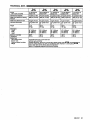
1
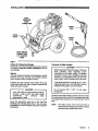
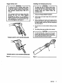
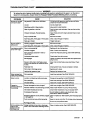
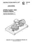
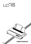
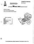
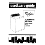
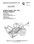
INSTRUCTIONS-PARTS LIST
0-0
This m U a l contains IMPORTANT
WARNINGS and INSTRUCTIONS
READ AND RETAIN FOR REFERENCE
HYDRA-CLEAN 2545,3040,3235
Pressure Washers
@
HYDRA-CLEAN 2545
PIN 800-701,Series A, 11 HP IIC ENGINE
PIN 800-702, Series A, 12.5 HP OHV ENGINE
2500 psi (1 72 bar)OPERATING PRESSURE
2900psl(200 bar) MAXIMUM WORKING PRESSURE
HYDRA-CLEAN 3040
PIN 800-703, Series A, 11 HP IIC ENGINE
PIN 800-704, Serles A, 12.5 HP OHV ENGINE
3000 psi (207 bar) OPERATING PRESSURE
3400psi (234 bar) MAXIMUM WORKING PRESSURE
HYDRA-CLEAN 3235
PIN 800-705, Series A, 11 HP IIC ENGINE
3200 psi (221 bar)OPERATING PRESSURE
3600psi (248 bar)MAXIMUM WORKING PRESSURE
GRACO INC. PO. BOX 1441 MINNEAPOLIS,MN 55440-1441
@COPYRIGHT1991, GRACO INC.
HIGH PRESSURE SPRAY CAN CAUSE SERIOUS INJURY.
FOR PROFESSIONALUSE ONLY. OBSERVE ALL WARNINGS.
Read and understand all instruction manuals before operating equipment.
FLUID INJECTION HAZARD
Pressure Relief Procedure
General Safety
To reduce the risk of serious
bodily injury, including fluid
This pressure washer generates very high
fluid
injection and splashing in the eyes or on the skin,
pressure. Spray from the gun, leaks or ruptured
components can inject fluid through your skin and into always follow this procedure whenever you stop
10 minutes, when shuttingdown,
spraying for more than
your body and cause extremely seriousbodily injury
or repairing any partof the system.
including the need for amputation. Also, fluid injected orand before checking
splashed into the eyes
or on the skin can cause serious
1. Engage the trigger safety latch.
damage.
NNER point the spray gun or wand at anyone or at any 2. Tum the sprayer off.
part of the body. NNER put hand or fingers over the
3. Remove the ignitioncable from the spark plug.
spray tip.
ALWAYS follow the Pressure Relief Procedure,before
cleaning or servicing any part of the sprayer.
NNER try to stop or deflect leaks with your hand or
body.
Be sure equipment safety devices are operating
properly before each use.
Medical Treatment
If any fluid appears to penetrate your skin, get
EMERGENCY MEDICALTREATMENTATONCE. DO
NOT TREAT AS A SIMPLE CUT. Tell the doctor exactly
what fluid was injected.
NOTE TO PHYSICIAN Injectionin the skinis a
traumatic injuty It Is lmpotiant to treat the Injury
surglcally .as soon as possible. Do not delay
treatment to research tawiciiy. Toxicity is a
concern' with some exotic coatings injected
direct@inM the bloodstream. Consultationwith a
p/astic surgeon or reconstructiVe hand surgeon
may be adrisable.
2
308-531
4.
Shut off the water supply.
5. Disengage the trigger safetylatch and trigger the
gun to relieve pressure, and then engage the trigger
safety latch again.
6. Before long-term (overnight) storage or
transporting of unit, disconnect the water supply
and turn off the fuel supply valve.
Spray Gun Safety Devices
Be sure all gun safety devices are operating properly
before each use.Do not remove ormodify any part of
the gun; this can cause a malfunction and result in
serious bodily injury.
SAFEPl LATCH: Whenever you stop spraying for a
moment, always set the gun safety latch
in the engaged
or "safe" position, making
the gun inoperative. Failure to
properly set the safety latch can resultin accidental
trlggering of the gun.
SPRAY TIP SAFETY: Use extreme caution when
cleaning or changing spray tips. If a spray tip clogs
while spraying, engage the gun safety latch
immediately. ALWAYS follow the Pressure Relief
Procedure and then remove the spray
tip to clean it.
FUEL AND EMISSION HAZARDS
NEVER flllthe fuel tank while the unit
is wnning or hot.
NEVER alter the throttle settlng, whichIs factory set.
The fuel used in this unit is combustible and when Tampering with this adjustment can damage the
pressure washer andwill void the warranty.
spilled on a hot surface can ignite and cause a fire.
ALWAYS fill tank slowly to avoid spilling.
NNER operate the' unit in a closed building. The
exhaust contains carbon monoxide, a poisonous,
odorless, invisible gas which can cause serious injury
or death if inhaled.
EQUIPMENT MISUSEHAZARD
General Safety
Any misuse of the pressure washer or accessories,
such as overpressurizing, modifying parts, using
incompatible chemicals and fluids,or using worn or
damaged parts, can cause them to rupture and Inresult
fluid injection, splashing in the eyes
or on the skin, or
other serious bodiiy injury, fire, explosionor properly
damage.
NEVER alter or modify any part of this equipment; doing
so could causeit to malfunction.
CHECK all spray equipment regularly and repair or
replace womor damaged parts immediately.
ALWAYS wear protecthre eyewear and appropriate
clothing. If using a chemicai injector, read and follow
the chemical manufacturer's literature for
recommendations on additional protective equipment,
such asa respirator.
System Pressure
This sprayer can develop high operating pressures. Be
sure thatail spray equipment and accessories are rated
to withstand the maximum working pressure of this
sprayer. DO NOT exceed the maximum working
pressure of any component or accessory used
in the
system.
Chemical Compatibility
BE SURE that all chemicals used in the chemical
injector are compatible with the wetted partsof the
hose, gun, wand and tip, as given
in the Technical Data
(inside back cover). Always read the chemical
manufacturer's literature before usinaany chemical in
this pressure washer.
HOSE SAFETY
High pressure fluid
in the hoses can
be very dangerous.
NEVER use a damaged hose. Before eachuse, check
If the hose developsa leak, split or rupture due to any entire hose for cuts, leaks, abrasion, bulging cover, or
damage or movement of the hose couplings.
kind of wear, damage or misuse, the high pressure
If any of
it can cause fluid
a injection injun/ or these conditions exist, replace the hose immediately:
spray emitted from
DO NOT try to recouple high pressure hose or mend
it
other seriousbodily injuryor property damage.
with tape or any other device.
A repaired hose cannot
ALL FLUID HOSES MUST HAVE STRAlN RELIEFS ON
contain the high pressure fluid.
BOTH ENDS. The strain reliefs help protect the hose
from kinksor bends at orclose to the coupling, which
HANDLEANDROUTE HOSES CAREFULLY:Do not pull
can resultin hose rupture.
on hoses to move the pressure washer.Do not use
chemicals whichare not compatible with the inner tube
T/GM€N all fluid connections securely before each
and coverof the hose.DO NOT expose Graco hoseto
loose
use. High pressure fluid can dislodge
a coupling
temperatures above200" F (93" C ) or below -40" F
or allow high pressure spray to be emitted from the
(-400 C).
coupling.
MOVING PARTS HAZARD
Moving parts can pinch or amputate fingers or other
body parts. KEEP CLEAR of moving parts when starting
or operating the pressure washer.
Pressure Relief Procedure before checking or
servicing the pressure washer
to prevent discharging
high pressure fluid from the gun.
NEVER operate the pressure washer without
all guards
and interlocks installed and functioning. Follow the
308-531
3
TERMS
WARNING: Alerts user to avoid or correct conditions
that could cause bodily injury.
NOW.
Identifies helpful procedures and Information.
CAUTION: Alerts user to avoid or comect conditions
that could cause damageto the equipment.
IMPORTANT
United Stales Government safety standards have been
adopted under the Occupational Safety and Health Act. These
standards-particularly the General Standards, Part 1910, and the Construction Standards,Part 1926-should be
consulted.
4
308-531
__
~~
INSTALLATION
Flgure 1
Check for Shipping Damage
Connect to Water Supply
CAUTION
Check the unit for any damage that may have occurred
' -I
in shipping. Notlfy the carrier Immediately if there
is
any damage.
Set Up
If you are using a downstream chemical injector, itinstall
between the pump unloader and the high pressure
hose, using the quick couplers provided.
Before attaching
to the water supply, check your
local plumbing code regarding crossconnection to the water supply. A backflow
preventer, P/N 801-133,is available to prevent
backflow of contaminated water into the fresh
water supply. Install it upstream from the pump.
Connect the high pressure hose between the pump
outlet and the gun inlet. Both of these connections are
made with quick couplers.
If inlet water pressureis over 60 psi (4.1 bar) a
regulating water valve,P/N 800-258,must be
installed at the garden hose connection.
Do not exceed
temoerature.
oerformance. if used.
Install the appropriate spray tip on the wand. See
Installing and Changing Spray Tips.you
If are using a
sandblaster kit,see its separate manual for installation
instructions.
1 6 0 O
F (70" C) inlet water
3/4ainch (19 mm) ID from
Connect a hose with at least
to the unit's3/4inch garden hose inlet.
the water supply
The supply hose should not
be more than50 ft(l5 m)
long.
NOTE The water source at the unit must have a
to that of the unit (see
minimumflow rate equal
Technical Data,inside back cover).
308-531
5
~
~~
STARTUP
Always use this start-up procedure to ensure that the
unit is started safely and properly.
1. Check oil levels.
Engine: Add SA€ 30 or low-30weigM detergentoil
as necessary.
Pump: AddSAE 20 or 30 weight non-detergent oil
as necessary, or use genuineCAT@pump oil.
NO=
All units are equipped witha low-oil sensor
that shuts the engine off ifthe oil level falls
below a certain level. If the unit stops
unexpectedly, checkboth the oil and the fuel
011 level each time the unit
is
levels. Check the
refueled.
2. Check fuel level.
WARNING
DO NOT refuel a hot engine. Refueling a hot
engine could cause afire. Use only fresh,
clean
regular or unleaded gasoline. Close the fuel
shutoff valve during refueling.
3. Rrn on the water supply.
CAUTION
Never run the unit dry. Costly damage to the
pump will result. Always be sure the water
supply Is completely turned on before
4. Trigger the gun until water sprays from the tip
indicating that the air
is purged from the system.
5. Open the fuel shutoff valve. Be sure the spark
plug
ignition cableis pushedfirmly onto the spark plug.
On those units equipped withan ignition shutoff
switch, put the switch in the ”on”
position and put
the throttle in the “run” position.
6. Start the engine.
NOTE:
For easier starting, have one person start the
pressure washer while another person
triggers the spray gun.
If the engine is cold, completely close the engine
choke. Grasp the starter rope, brace one foot on the
pressure washer chassis and
pull rope rapidly and
firmly. Continue holding the rope asit returns. Pull
and return the ropeuntil the engine Starts.In cool
weather, the choke may have
to bekept closed for
10 to 30 seconds before opening it to keep the
engine running. Otherwise, open the choke as soon
as the engine starts.
If the engineis warm, leave the choke open, or just
partly close it. Start the engine as described in the
preceding paragraph. When it starts, be sure to
open the choke completely.
CAUTION
On recoil start engines, never let the starter rope
retum by itself. could
It
jam the recoil system.
7. ALWAYS engage the gun’s trigger safety latch
whenever you stop spraying, even for
a moment, to
reduce the risk of
fluid injection or splashing in the
the skin if the gunis bumped or triggered
eyes or on
accidentally.
8. ALWAYS observe the following CAUTIONS avoid
to
costly damage to the pressure washer.
DO NOT allow the pressure washer toidle for
more than10 minutes. Doingso may cause the
recirculating water to overheat and seriously
damage’the pump.Tum off the pressure washer
if it willnot be spraying or cleaning at least every
10 minutes. If heated inlet water
is used, reduce
this time further.
DO NOT run the pump dry, which will quickly
damage the pump.Be sure the watersupply is
fully turned on before starting the pump.
DO NOT operate the pressure washer with the
inlet water screen removed. Tnis screen
helps
keep abrasive sediment out
of the pump, which
could clog or scratch the pump. Keep this
screen clean.
DO NOT pump caustic materials; such
materials mav corrode the
ourno comoonents.
9. See thechemical injectoror sandblasterkit manual
for detailed cleaning
infomation if these
accessories are used.
6
308-531
Trigger SafetyLatch
Installing and Changing Spray Tips
WARNING
To reduce the risk of serious bodily injury,
including fluid injection, splashing
inthe eyes or
on the skin,ALWAYS engage the trigger safely
latch whenever spraying stops, even for a
moment.
in the engaged position, the trigger safety latch
prevents the gun from
being triggered
accidentally by hand or if it is dropped or
bumped. Be sure the latch
is pushed fully down
when engaging it or it cannot prevent the gun
from being triggered.See Figure 2.
WARNING
To reduce the risk of serious bodily injury,
including fluid injection
or splashing inthe eyes
or onto the skin, use extreme caution when
changing spray tips. ALWAYS follow the
procedure below.
1. Follow thePressure ReliefProcedure.
2. Point the gun and wand away from yourself and
anyone else.
3. Without holding your hand over the spraytip (A),
pull back the quick coupler ring (6). Remove
oldthe
tip and/or installa new one, and then release the
ring. See Figure3.
4.
Be sure the tip is secure before starting to spray
again.
5. Tip holding holesare provided on the chassis.
CAUTION
To avoid blowingthe O-ring out of the quick
coupler, due to thehigh pressure in the system,
never operate the pressure washer without
a tip
TRIGGER SAFETY LATCH SHOWN ENGAGED
TRIGGER SAFETYLATCH SHOWN DISENGAGED
Figure 2
Rgure 3
308-531
7
SHUTDOWN, FLUSHING
AND STORAGE
WARNING
Pressure Rellef Procedure
To reduce the risk of serious bodily injury,
including fluid injectionand splashing in the
eyes, .or on the skin, always follow this
procedure whenever you stop spraylngformore
than 10 minutes, when shutting down, and
before checking or repairing any part of the
system.
1. Engage the trigger safety latch.
2. Tum the sprayeroff.
3. Remove the ignition cable from the spark
Plug.
4.
Shut off the water supply.
5. Disengage the trigger safety latch and
trigger the gun
to relieve pressure, and then
engage the trigger safety latch again.
6. Before long-term (overnight) storage or
transporting of unit, disconnect the water
supply, and tumoff the fuel supply valve.
1. If the pressure washer will be exposed
to freezing
temperatures, drainall water out of the pump. if it
must be stored in freezing temperatures, flush the
unit with a 50% anti-freeze solution. Relieve
pressure. Flush the pressure washer
before usingit
again to remove the anti-freeze.
NOTE:
An anti-freeze flush kit, P/N 802-327, is
available to make flushing easier,
CAUTION
If water dOeS freeze in the pressure washer,
thaw it in a warmroom before trying
to start it.
DO NOT pour hot water on or into the pump;
it
2. After each use, wipe all surfaces of the pressure
washer with a clean, damp cloth.
3. Perform the appropriate maintenance. See
maintenance chart.
8
308-531
MAINTENANCE
Observing regular maintenance intervals helps ensure
that you get maximum petformance
and life from the
pressure washer.
There is a break-in period for the engine, pump
and
gear reducer (if used). After changing the
oil in these
components following their respective break-in
periods, the interval between required changes is
longer.
If the unit Is operating in dusty conditions, these
maintenance checks shouldbe made more often.
To reduce the risk of serious bodily injury,
including fluid injection, splashing
inthe eyes or
on the skin or injury from moving parts, always
Relief ProcedureWarnlng
follow the Pressure
before proceeding.
Interval
Daily
After first 5
hours of
operation
Each 25 hours
of operation
What to do
Clean water inlet screenand
filter. Check engine and pump
oil
levels. Fill as necessary. Check
gasoline level. Fill as necessary.
Change engine break-in oil.
Drain oil when warm. Use SA€
30 or 1OW-30 detergentoil.
Clean and remove air cleaner
foam. Wash with water and
detergent. Dry thoroughly. Rub
With oil and squeeze to distribute
DiI.
After first 50
hours of
operation
Each 100 hours
of operation
or 3 months
Each 500 hours
3f operation
31 6 months
Change pump break-inoil. Use
SAE 20 or 30 no detergent 011,
x genuine CAgpump oil. .
Clean orreplace paper air
:leaner cartridge. Tap gently to
'emove dirt. Change engine
oil.
Jse SAE 30 orlow-30
jetergent oil.
:hange pump oil. Use SA€ 20 or
30 n n detergent oil,or genuine
:A
pumpoil.
4-
I
TROUBLESHOOTING CHART
WARNING
To reduce the risk of
serious bodily injury, including fluid injection, splashing
in the eyesor on the skin or
injury tom moving palls, always follow the Pressure Relief Procedure Warnlng before proceeding.
1
PROBLEM
Engine will not stail
or is hard to start
CAUSE
No gasolinein fuel tank M carburetor.
SOWTION
Fill the tank with gasoline, open
fuel shut off valve.
Check fuel line and carburetor.
Add to proper level.
Low oil.
Move switchto Start position.
W S l o p switch in Slop position.
Drainfuel tank and carburetor. Use newfuel and dry
Water In gasoline orold fuel.
spak Plug.
Open choke and crank engine several times to clear
Choked improperly. Flooded engine.
out gas.
Remove and clean.
Dirty air cleaner filter.
Spark plug dirty, wronggap or wrong type. Clean, adjust the gap or replace.
Trigger spray gun.
Spray gun closed.
Remove and clean.
Partially plugged air cleaner filter.
Spark plug dirty, wrong gap or wrong type.Clean, adjust the gap or replace.
Replace with tip of piopsr size.
Low pressure and101 Worn or wrong size tip.
pump runs rough
inlet filter dogged.
Clean. Check more frequently.
See PUMP SERVICE.
Check filter. Replace packings.
Worn packings.abrasivs inwater or
natural wear.
Check water flow rateto pump.
Inadequate water supply.
Tighten or replace;use correct beits and replace both
Belt slippage.
at same time.
valve assemblies. Check
Fouled or dirty inlet or discharge valves. Clean inlet and discharge
Even a small particle
can cause the valve filter.
lo stick.
Restricted inlet.
Check garden hose, maybe collapsed or kinked.
Worn inlet or discharge valves.
Replace worn valves.
Leaking high pressure hose.
Replace high pressure hose.
Engine misses or
lacks power
Water leakage from Worn packings.
under pump manifol
Install new packings.See PUMP SERVICE.
Water In pump
Humid air condensing inside crankcase.
Nom pkings.
Oil seals leakino.
Change oilas specified in MAINTENANCE.
Install new packings.See PUMP SERVICE.
Install newoil seals. See PUMP SERVICE.
Frequent or
premature failure of
the packings
b
r
e
d
.damaged orworn plungers.
ruKaslve materialin the fluid beingp u m p
Inlet water temperaturetoo high.
3verpressurizing pump.
thc
Strong surging at
inlet and low
pressure on the
Install new plungers.See PUMP SERVICE.
Install proper filtration on pump inlet plumbing.
Check water temprature; may notexceed 160°F.
Do not modify any factory-set adjustments.
See
EQUIPMENT MISUSEHAZARD.
to partially pluggec Clean or replace tip.See Installing and Changing Spray
3cessive pressure due
3r damaged tip.
lips.
'ump running too long without spraying. Never run pump more than
10 minutes without spraying,
Do not run pump wlthoul water.
3unning pump dry.
=oreign particlesin the inlet or discha e
Clean or replace valves.See PUMP SERVICE.
lake or wom inlet and/or discharge
va yes.
'B
308-531
Q
PARTS DRAWING
800-701 and 800-702
PARTS LIST
800-701 and 800-702 Hydra-Clean@ 2545 Pressure Washer
REF
NO.
1
PART
NO.
DESCRIPTION
QTY
800-392 GUN & WAND ASSEMBLY
fincl. 16. 21., 34.
35.52.5 3 .
~,
h,56,57)
1
31
100-023 WASHER. Flat 5/16
801-941 SCREW, Cap, hexhd.
5/16-18 X 1
9
801 -539 BUMPER803-926 BELT GUARD
803-534 LABEL, Belt Guard
800-676 CHASSIS
9
100-188 NUT,Hex5/16-18
100-21 4 WASHER, Lock 5/16
15
801-550 WHEEL & TIRE ASSEMBLY
2
801-612 WASHER, Flat 1/2
2
801-020 NUT, Lock 1/2-13
2
801-556 AXLE
1
800-678 BRACKET, Rail Stiffener
1
801 -546 SCREW, Cap, hex hd.
3/8-16~1-1/4
4
801-569 QUICK COUPLER, Female 3/8
(incl. 34) 2
803-303 LABEL, Model 2545
1
800-1 60 FRONT LEG ASSEMBLY
~
2
3
4
5
6
7
8
9
10
11
12
13
14
15
16
17
18
19
"
~
21
22
803-925
801 -571
801-568
803-298
23
800-375
24
800-652
20
". . ~ "..
REF
NO.
41
42
25
26
27
28
29
30
31
32
33
34
35
36
156-082
154-594
801-022
37
38
39
802-363
181 -867
801-494
802-01 6
176-250
172-981
801-548
800-1 74
800-1 73
800-341
800-305
803-882
~
~~~
43
44
45
46
47
48
49
53
51
52
53
54
55
56
57
58
59
60
61
62.
63
64
65
66
67
Ea
69
70
71
72
73
74
75
76
77
78
PART
NO.
DESCRIPTION
QTY
801 -21 7BUMPER. Rubber
1
108-842 SCREW, Cap, hex hd.
(used on 800-701 only)
1
801-21 0 SCREW, Cap, hex hd.
(used on 800-702 only)
1
801-1 68 BELT, Drive
2
801-898 HUB, Engine
1
801-896 SHEAVE, Engine
1
804-255 HUB, Pump
1
802-1 17 SHEAVE, Pump
1
177-144 LABEL, Belt Guard
1
803-531 BASEPLATE, Belt Guard
1
803-246 GUARD, Muffler
(used on 800-701 only)
1
801-522 SCREW, Cap, hex hd.
2
801-009 QUICK COUPLER. Female11'4
1
801-134
1
801-674
1
111-040
4
803-350 GUN, Spray(see Inst.
Manual 308-51 I)
156-849 NIPPLE, Hex 3/8
801 -531 SCREW, Cap, hex hd.
3/8-16 X 7
1
801-504 BUMPER. Rubber
1
801-505 RETAINER, spring
1
801-593 SPRING
1
801-506 BOOT
1
801 -537 LEG, Front
1
801-499 NUT, Lock 3/8-16
1
801-090 QUICK COUPLER, Male 1/4
4
801-730 TIP, Spray ooO55
1
801-729 TIP, Spray 15055
1
803-174 TIP; Spray 25055
1
803-175 TIP, Spra 40055
1
802-907 CONNEC!TOR,
Fuel
1
(used on 800-702 only)
801-919 BRACKET, Fuel Connector
(used on 800-702 only)
801-971 CLAMP. Hose
(used on 800-702 only)
801-629 LINE. Fuel
(used on 800-702 only)
801-71 6 LABEL, Warning
(used on 800-702 only)
803-881 LINE, Fuel w/Squeeze Bulb
(used on 800-702 only)
802-025 TANK. Fuel
(used on 800-702 only)
801-008 LABEL, GracoG
(used on 800-702 only)
802-026 BARB, Hose 1/4X 5/16
(used on 800-702 only)
308-531 11
PARTS DRAWING
800-703 and 800-704 Hydra-Clean@3040 Pressure Washer
PARTS LIST
800-703 and 800-704 Hydra-Cleano 3040 Pressure Washer
. .....
2
3
4
5
6
7
8
9
10
11
12
13
14
15
16
17
18
19
20
21
22
23
24
25
26
27
28
29
30
31
32
33
34
35
36
37
38
39
NO.
DESCRIPTION
ON
800-392 GUN &WANDASSEMBLY
fincl. 16. 21.. 34.
. 35.52. 53.
1
k4,56,57)
31
100-023 WASHER. Flat 5/16
801 -941 SCREW, Cap, hexhd.
9
5/16-18 X 1
1
801 -539 BUMPER
1
803-926 BELT GUARD
1
803-534 LABEL, BeltGuard
1
800-676 CHASSIS
9
100-188 NUT,-Hex5/16-18
100-214 WASHER, Lock 5/16
15
2
801-550 WHEEL &TIRE ASSEMBLY
2
801 -61 2WASHER, Flat 1/2
2
801-020 NUT, Lock 1/2-13
1
801 -556 AXLE
1
800-678 BRACKET, Rail Stiffener
801 -546 SCREW, Cap, hex hd.
4
3/8-16 X 1-1/4
801 -569 QUICK COUPLER, Female 3/8
2
(IflCl. 34)
1
803-161 LABEL, Model 3040
800-1 60 FRONT LEG ASSEMBLY
61, 62,
(incl. 2, 9, 17, 59,
63.64)
1
803-925 HANDLE 1
801-571 HOSE, Hi h Pressure 3/8 x50' 1
801 -568 QUICK C8UPLER. Male 3/8 2
Cam hexhd.
803-298 SCREW.
~.
5/16-i8x'i-W
800-375 HOSE ASSEMBLY W/QUICK
COUPLERS
(incl. 16, 2 0 , 21, 34)
800-652 FUEL TANK ASSEMBLY
(incl. 72, 74, 75, 76,
7 7 , 78)
(used on 800-704 only)
802-01 6 BRACKET. Rail Stiffener
176-250 LABEL, Chassis
172-981 LABEL. Chassis
5
801-548 GROMMJIET, Rubber
800-314 TIP ASS'Y. 00045 (incl. 6 5 . 661 1
8007315 TIP ASS3f15045~(I~cl.
65, 67j ~'1
8oO-316 TIP ASS'Y. 25045(incl. 65. 68) 1
800-31 7 TIP ASS'? 40045 (incl.
69j 1
PUMP ASSEMBLY (see page16) 1
156-082 O-RING, Quick Coupler 3/8
2
154-594 O-RING, Quick Coupler 1/4 1
801-022 SCREW, Cap, hex hd.
5/16-18 x 3/4 4
802-363 LABEL. Caution
1
181-867 LABEL; Warning 1
801 -494 ENGINE. 11 hD.Briaas &
Stratton I/C ' .
(used on 800-703 only) 1
803-882 ENGINE, 12.5hp, Briggs&
Stratton Vanguard OHV
(used on 800-704 only) 1
60.
65;
"
REF PART
QN
NO. NO. DESCRIPTION
41 801-217 BUMPER, Rubber
1
42 108-842 SCREW,
Can hex hd.
(used-on860-703 only) 1
801-210 SCREW, Cap. hex hd.
1
(usedon b60-704 only)
2
43
801-168 BELT, Drive
1
44
801-898 HUB, Engine
1
45
801-91 1 SHEAVE. Enaine
HUB, Pump
46 804-255
47 804-138
SHEAVE. PumD
48 177-144 LABEL, Belt Guard
1
1
49 803-531 BASEPLATE,
Belt Guard
50
803-246 GUARD, Muffler
lused
1
-.
- - on
-. . 800-703
-.
. . . onlv)
-. ..
2
51 801-522
SCREW, Ca , hex hd.
52 801-009
QUICKCO~PLER,
Female 1/4
(incl. 35)
53
801-134 WAND, 32"
54 801-674
SLEEVE. 28"
55
111-040 NUT, LoCk5/16-18 4
56 803-350 GUN, Spray (see Inst.
1
Manual 308-51 1)
1
57 156-849 NIPPLE, Hex 3/8
58
801-531 SCREW, Cap, hex hd.
318-1 6 X 7 1
59
801-504 BUMPER, Rubber
1
60
801-505 RETAINER, Spring 1
1
61 801-593 SPRING
1
62 801-506 BOOT
63
801-537 LEG, Front
1
1
64 801-499 NUT,
Lock 3/8-16
65
801-090 QUICK COUPLER, Male 1/4 4
66 803-106
1
TIP, Spray OOO45
67 803-107
TIP, Spray 15045
1
68
803-108 TIP, Spray25045 1
1
40045
69 803-109 TIP, Spra
70
802-907 CONNE&OR. Fuel
(used on 806-704 only)
71
801-919 BRACKET, Fuel Connector
(used on 800-704 only)
801-971 CLAMP. HOW
72
(used on 800-704 only)
801-629 LINE. Fuel
73
(used on 800-704 only)
801-716 LABEL, Warning
74
(used on 800-704 only)
803-881 LINE, Fuel w/Squeeze Bulb
75
(used on 800-704 only)
802-025 TANK, Fuel
76
(used on 800-704 only)
77
801-008 LABEL, Graco G
(used on 800-704 only)
802-026 BARB, Hose 1/4 x 5/16
78
(used on 800-704 only)
~~
~~
~~
~
,I
~~
~~
308-531 13
PARTS DRAWING
800-705 Hydra-Clea
14
308-531
PARTS LIST
800-705 Hydra-Cleano 3235 Pressure Washer
REF
NO.
1
2
3
4
5
6
7
8
9
10
11
12
13
14
15
16
17
18
19
20
21
22
23
25
26
27
28
29
30
31
32
PART
""~.
DESCRIPTION
QTY
800-392 GUN & WAND ASSEMBLY
(incl. 16.. 21.
. 34.
. 52.
. 53. 54.
NO.
56,57)
100-023 WASHER. Flat 5/16
801-941 SCREW, Cap, hex hd.
5/16-18X 1
801 -539 BUMPER
803-926 BELT GUARD
803-534 LABEL, Belt Guard
800-676 CHASSIS
1 00-188 NUT, Hex 5/16-18
100-21 4 WASHER, Lock 5/16
801-550 WHEEL & I R E ASSEMBLY
801 -61 2WASHER, Flat 1/2
801-om NUT, Lock 1/2-13
801-556 AXLE
800-678 BRACKET, Rail Stiffener
801 -546 SCREW, Cap, hex hd.
3/8-16X 1-1/4
801 -569 QUICK COUPLER, Female3/8
(incl. 34)
803-904 LABEL, Model 3235
800-1 60 FRONT LEG ASSEMBLY
(incl. 2, 9, 17,59, 6 0 , 61, 62,
63.64)
803-925 HANDLE
801 -571 HOSE, Hi h Pressure3/8 x 50'
801-568 QUICK CJUPLER, Male3/8
hex hd.
803-298 SCREW.
5/16-i8Can.
x'3-1i2
~~
~~~~
1
31
9
1
1
1
1
9
15
2
2
2
1
1
4
2
1
1
1
1
2
1
800-375 HOSE ASSEMBLY W/QUICK
COUPLERS (incl.16,20,21) 1
802-01 6 BRACKET, Rail Stiffener
I
176-250 LABEL, Chassis
1
172-981 LABEL. Chassis
1
801-548 GROMMET, Rubber
5
800-124 TIP ASS'Y, OOO4 (incl. 6 5 , 66)
1
800-125 TIP ASS'Y1504 (incl. 6 5 , 67)
1
800-126 TIP ASS'Y 2504 fincl. 65. 68\
1
$ .I
800-127 TIP ASS'f 4664 jincl. . 6
.
65;
"
REF
.".
NO.
33
34
35
36
37
38
39
41
42
43
44
45
46
47
48
49
50
51
52
53
54
55
56
57
58
59
M)
61
62
63
64
65
66
67
68
69
PART
......
NO. DESCRIPTION
QN
PUMP ASSEMBLY (see page16)l
2
156-082 O-RING. Quick CouDler 3/8
154-594 O-RING; Quick Coupler i/4
1
801-022 SCREW. Can. hex hd.
5/16-16 X'3/4
4
802-363 LABEL. Caution
1
iSi-667 LABEL. Warning
1
801-494 ENGINE, 11 hp, Briggs &
Stratton I/C
1
801-217 BUMPER, Rubber
1
803-535 SCREW, Cap, hex hd.
1
801 -285 BELT, Drive
2
801-898 HUB, Engine
1
801-897 SHEAVE, Engine
1
804-255 HUB, Pum
1
801-004 SHEAVE, ump
1
177-144 LABEL, Belt Guard
1
803-531 BASEPLATE, Belt Guard
1
803-246 GUARD, Muffler
1
80-522 SCREW, Cap, hexhd.
2
801-009 QUICK COUPLER, Female114
(incl. 35)
1
801-134 WAND, 3 2
1
801 -674 SLEEVE, 28"
1
111-040 NUT, LOCk5/16-18
4
803-350 GUN, Spray (see Inst.
1
Manual 308-51 I)
156-849 NIPPLE, Hex 3/8
1
801-531 SCREW, Cap, hex hd.
3/8-16 X 7
1
801-504 BUMPER, Rubber
1
801-505 RETAINER, Spring
1
801-593
1
-.
. - - - SPRING
-. . ... .801-506 BOOT
1
801-537
LEG. .Front
1
.
..
. -. ..
801-499 NUT, Lock 3/8-16
1
801-090 QUICK COUPLER,Male 1/4
4
1
801-599 TIP, Sdrav OOO4
801-600 TIP, Spray 1504
801-601 TIP, Spray 2504
801-602 TIP, Spray 4004
~
~
~
~~~
~~~
8
"
~
_~_.
308-531
15
PARTS DRAWING
Pump Assembly
16
308-531
~
PARTS LIST
Pump Assembly
REF PART
NO. NO.
804-093
1
."
2
804-154
801 -028
3
4
804-181
5
804-1 89
6
804-1 55
7
804-171
8
804-1 50
9
802-189
804-089
10
11
804-237
"
12
13
14
15
16
17
18
19
20
21
22
23
24
25
26
27
28
29
30
31
32
33
34
35
36
37
~
804-224
804-080
804-109
804-124
804-1 37
804-1 93
804-21 3
804-219
804-223
804-1 26
801-031
804-121
804-208
804-21 6
804-220
804-234
801 -038
KIT C21
801-040
804-21 4
804-222
KIT C21
804-217
KIT C21
804-1 18
KIT C21
DESCRIPTION
804-098
KEY
1
1
1
1
1
1
1
1
1
1
CRANKCASE
O-RING, Oil Fill Cap
CAP, Oil Fill
O-RING, Crankshaft Cover
COVER, Crankcase
GASKET, Oil Sight Gauge
GAUGE, Sight
O-RING, Drain Plug
PLUG, Drain
SCREW, Cap, hex hd./cross
recess (6mm x 16mm)
12
CRANKSHAFT
1
BEARING
2
SEAL, Oil, crankshaft
1
O-RING, Crankshaft Cover
2
COVER, Crankshaft
1
COVER, Crankshaft
1
RETAINER, Packing, front
3
ROD, Assembly Connecting
3
ROD, Plunger
3
PIN, Plunger Rod
3
SEAL, Oil, plunger
3
WASHER, Sling&
3
RETAINER, Packing, rear
3
PLUNGER.. Ceramic
3
GASKET, Plunger
3
STUD, Retaininp
(6mm x64,5im)
3
RING, Backup, plunger retainer 3
O-RING, Plunger Retainer
RETAINER, Plunger
3
WASHER, Keyhole
3
MANIFOLD
1
O-RING, Packing Retainer
RETAINER, Packing 3
PACKING, Low Pressure
ADAPTER, Male
3
PACKING, High Pressure
Repair KR
Part No.
Valve
QTY
~~
I
~~
i
i
"
Ref
No.
Descrlptlon
Seat
40
SEAT, Valve
41 VALVE
42 SPRING, Valve
43
RETAINER, Valve
45
I
1
Cap
RING. Backuo.
valvecap
I
REF PART
NO. NO.
DESCRIPTION
QTY
38
804-120 ADAPTER, Female
3
39 KITC3
O-RING, Valve Seat
40 KIT C3 SEAT, Valve
VALVE
41
KITC3
42 KIT C3
SPRING, Valve
43 KlTC3
RETAINER, Valve Spring
44
KIT C3
O-RING, Valve Cap
45
KIT C3
RING, Backup, valve cap
46 804-221
CAP, Valve
6
47 802-178
WASHER, Lock, lOmm
2
48
804-232 SCREW, Cap, sockethead
(1 Ommx 35mm)
2
49
804-077 WASHER, Lock, 6mm
12
50
804-075 WASHER, Flat, 6mm
2
51 101-754
PLUG, Hex Socket 3/8
1
52
100-361 PLUG, Hex Socket 1/2
1
PUMP
53 804-246
1
54
101-754, PLUG, 318
1
55
800-113 FILTER (see Instruction
manual 801 -744)
1
56 100-214
WASHER, Lock 5/16
4
57 108-842
SCREW, Cap, hex hd.
8mm x 16mm
4
BRACKET, Pump
58 800-691
2
NIPPLE, Hex 1/2 x 3/8
59 159-239
1
TEE, 1/2
60 801-106
1
NUT, Garden Hose
61 801-111
1
62 801-110
ADAPTER, GardenHose
1
63
801-112 STRAINER, Garden Hose
1
64 801-568 QUICK COUPLER, Male, 318 1
65 800-323
UNLOADER, 2500psi
1
800-324 UNLOADER, 3000psi
1
800-325 UNLOADER, 3200psi
1
66 803-142
NIPPLE, Hex,
3/8 NPT x 112 NPSM
1
67 803-141
HOSE ASSEMBLY, Bypass
1
68
803-083 LABEL, Keep From Freezing 1
69 156-849
NIPPLE, Hex 318
1
70 100-361
PLUG, 1/2
1
~~~~
KR
No.
~~~~
I
Repalr KR
Part No.
Description
Packing
37
O-RING, Plunger
Retainer
O-RING, Packing
Retainer
PACKING, Low
Pressure
PACKING, High
Pressure
.
308-531
17
PUMP SERVICE
Servicing the Valves
Reassembly:
1. Remove the hex valve plug.
1. Carefully examine each ceramic plunger for scoring
2. Examine the O-ring under the plug for cuts or
if wom. Lubricate new O-ring
distortion and replace
before installing.
Note:
3. Grasp valve retainer
by tab at the top with
pliers and
remove from valve chamber. Valve parts usually
separate during removal.
Note:
4.
A special tool will be neededto remove the
seat from the manifold.A reverse pliers ora
standard vise grip and1/4”
a x 3”bolt to fit I.D.
of seat Inserted under the edge
of the seat,will
pry the valve seat out easily.
Examine all valve parts for wear and replace with
preassembled valve assembly in sefvice kit
containing retainer, spring, valve, valve seat,
O-ring, and back-up ring.
5. Grasp new valve assembly by at
tabtop with pliers,
or cracks, replaceifwom and slip onto plunger rod.
Ceramic plunger can only be installed one
direction (frontto back). Do not force onto rod.
2. Examine plunger retainer and stud and replace
if
worn.
Note:
Thread stud into plunger retainer.
3. Examine O-ring. back-up
ring and gasket on
plunger retainer and replace
ifwom or cut. Lubricate
and to avoid
O-ring for ease of installation
damaging O-rings.
Note:
First install gasket, then back-up ring and
O-ring.
4. Thread plunger retainer and stud assembly into
to over torque.
plunger rod. Exercise caution not
5. Saturate new oil wick by soaking in oil, place in
immerse in oil and push into valve chamber. Be
seal retainer andslip retainer over ceramic plunger.
certain valve assembly is square in valve chamber.
6. ApplyLoctite242tovakreplug,threadintomanifold
port and torque per
chart.
Note:
Corrosion Resistant models require thecoil
spring installed in the
Valve Plug.
Servicing the Pumping Section
6. Replace oil pan.
7. Tum shaft by hand to line up plungers so end
plungers are parallel.
8. Carefully slip manifold onto plungers, keeping
manifold level, and tap with mallet
to bring manifold
flush with crankcase.
Dlsassembly:
1. Remove the four
(4)hexnuts ortwo(2)boltsfromthe
manifold (varies with model).
9. Replace washers and nuts
or bolts and torque per
chart.
2. Rotate crankshaft by handto start separation of
Servicing the Seals and V-Packings
manifold from crankcase. Support the underside of Disassembly:
to remove
the manifold and tap lightly with a mallet
1. Remove the manifold as described.
the manifold assembly.
CAUTION
Keep manifold properly aligned with ceramic
plungers when removing to avoid damage to
either plungers or seals.
3. Remove oil pan and slide out seal retainer with
wicks.
2. With crankcase side of manifold facing up, unscrew
the seal case from the manifold using
a special key
wrench.
3. Remove O-ring from seal case.
4. Remove snap ring and low pressure seal from the
seal case. Seals are generally removed easily
without anytools.
4. Using a wrench, loosen the plunger retainer. Grasp
ceramic plunger and push toward crankcase until 5. Hlgh Pressure Seal Models: The high pressure
seal is generally easily removed from the manifold
plunger retainer pops out.
without anytools. Ifextremely worna reverse pliers
5. Remove plunger retainer with copper gasket,
may be used.
back-up Ring andO-ring.
6. V-Packlng Models: The female adapter, two
6. Remove plunger from plunger rod.
v-packlngs and male adapter are easily removed
from manifold without tools. If extremely wom a
reverse pliers maybe used.
18
308-531
Reassembly:
Servicing Crankcase Section
V-Packlng Models:
1. Lubricate high pressure packing area in manifold.
1. While manifold, plungers and seal retainers are
removed, examine crankcase seals for wear.
2. Insert male adapter with notches down and
"v" side
2. Check oil level and for evidence of water
in oil.
UP.
3. Lubricate v-packings and install one-at-a-time
with grooved side down.
4. Next install female adapter with grooved side
down.
5. Examine seal case O-ring and replace if wom.
Lubricate new O-ring before installing.
3. Rotate crankshaft by hand to feel for smooth
bearing movement.
4.
Examine crankshaft oil seal externally for drying,
cracking or leaking.
5. Consult factory or your
local distributorif crankcase
service is evidenced.
Torque Chart
6. Thread seal case into manifold and tighten with key Pump Part Thread
Tool Slze Torque
wrench.
Plunger M5
11 mm hex 80 in. Ibs.
Retainer
Hlgh Pressure Seal Models:
ME x 1.25 13 mm hex 125 in. Ibs.
Manifold
1. Lubricate seal area in manifold.
M10x1.25 17mmhex 217in.Ibs.
2. Carelully squareseal intopositlonby hand with the
metal grooved side up.
3. Examine seal case O-ring and replace if wom.
Lubricate new O-ring before installing.
4.
Next secure high pressure seal into position by
threading seal case into manifold. Tighten seal
case with key wrench.
~~
Valve
Covers
M10 17 mm hex 217 in.
ibs.
24 mm
75 fl. Ibs.
27 mm
75 fl. ibs.
Low Pressure Seal-All Models:
1. Examine seal for wear or broken spring and
lace if
necessary.
2. Install low pressure seal in seal case with garter
spring down.
3.
Reinstallhap ring. Be certain snap ring
is a tight fit.
Replace if it can be easlly tumed.
4.
Replace manifold on pump as described and
torque per chart.
308-531 19
ACCESSORIES
(Must be purchased separately)
DOWNSTREAM CHEMICAL INJECTORKIT
800-1 17 & 800-649
For injecting harsh cleaning chemicals downstream
from the pump. 800-649 is stainless steel construction.
UPSTREAM CHEMICAL INJECTOR KIT
800-257
WATER SANDBLASTING KIT800-120
For abrasive cleaning of stubborn dirt and paint.
Requires a spray tip whichis not included inkit (2545
uses 801-729, 3040 uses 803-107. 3235 uses
. -",.
Rfll-l%Nl\
"
ANTI-FREEZE FLUSH KIT 802-327
For injecting mild cleaning chemicals upstream into the For flushing system with 50% anti-freeze solution prior
pump.
to transporting or storing pressure washer in below
freezina temoeratures.
BACKFUlW PREVENTOR 801-133
Prevent back-up of contaminated water into fresh
supply. Install upstreamof pump.
20
308-531
-
.
INLET PRESSURE REGULATOR800-258
Regulates inlet water pressure to 60 psi (4 bar)
maximum.
TECHNICAL DATA
Engine
(all 4 cycle, airwaled)
Gasoline TankCapacity
Water Pump Maximum Working
pressure
Water Pump MaximumFlow
Inlet Hose Connection
Weight
Dimensions
Lensth
width
Height
Maximum Inlet Water
Temperature
wetted patts
High Pressure Hose
Bypass Hose
PrESiUre Washer (including
fttings)
Model
800-701
11 HP B ' gs &
Stratton
lfis
Model
"Id
800-702
12.5 HP Briggs &
SlrattonOHV
11 HP Bri gs 8
Stratton !/I
Model
800-704 800-703
12.5 HP Briggs &
StrattonOHV
Model
800-705
1/8
11 HP Bri gs &
Stratton
6 quarts (5.7 liter) 24 quarts (23 li) 6 quarts (5.7 l i r ) 24 q w l s (23 l i r )
2500 psi (172 bar) 25M) psi (172 bar) 3wo psi (207 bar) 3wo psi (207 bar)
6 quarts (5.7 liter)
3200 psi (221 bar)
4.5 gpm (17 Ipm) 4.5 gpm (17 Ipm)
3/4'garden hose 314' garden hose
(0
213 Ib
(97 kg)
4
6
'
1168mm)
4 gpm (15 Ipm)
314' garden hose
3.5 gpm (13 Ipm)
34' garden hose
222 Ib
(101 kg)
213 Ib
(97 kg)
222 Ib
(101kg)
213 Ib
(97 kg)
46' 1168mm)
46' 1168mm)
46' 1168mm)
660mm
,26'
.km
j
46' 1168mm)
30' mmm)
26' 660mm)
16O'F
(70%)
160-F
(70'C)
(0
(0
26'
3
0'k660mm
mmi
26"
3
0'k660mm
mmj
26'
3
0'b660mm
mmi
V°C)
roooc)
BOW
16O'F
-
4 gpm (15 Ipm)
314' garden hose
1WF
16O'F
(0
(0
I
P
AcrylonMle and Buna-N m e r and tube
Synthetic yarnand EPDM
all0 s Brass Copper. Nylonmic,
Anodized aluminum, Aluminum or bronze
PTFE composite
Buna-N, Cotton phenolic, 303. 304. and316 dainles steel. Polymide-1
moplasdc. PTFE
Carbon steel, Zinc with or wMout yellow chromate plate
Tellon" is a registered trademark of the DuPonl Company
308-531 21
THE GRACO WARRANTY
WARRANTYAND DISCLAIMERS
Grawwanantsallequipmentmanutacturedbyit~baeringitsnama~obehaelmmde~~inrnaterial
andwarkmanshiponthedateofsalebyanauthorizedGracodistributortotheoriginalpumhaserforuse.
Aspumhaser'ssoleremactyforbreachofmiswarranty,Gracowiil,foraperiodoftwentyfourmonthsfmm
dateofsale,repairorreplacaanypartdtheequipmentpmvendefeotive.Thlswarrantyeppiiesoniywhen
the equipment Is Installed. operated and maintained in accordance with Graco's w h n
recommendations.
This warranty does
not cover. andGraw shall not be liablefor, any kdunction, damage orwear caused
by faulty installation. misapplication. abrasion, corrosion. inadequate or impmper maintenance.
negligence. accident.
M SubsMon d non-Graco component parts. Nor shall
Gram be
iiableforrn~nction,damageorwearcausedbytheinwmpatibilitywithGracoequipmentofsbuctures,
accessories. equipment or materials not suppliedby Gram. or m e improper design, manufacture.
installation. operation or maintenance
of sbuctures. accessories. equipment or materials not
suppliedby
GW.
tampering.
This warranty is conditioned upon the prepaid return d the equipment claimedto be d e W e for
examination by Graw to mMy the claimed defect. If me claimed defect is
verified. Graco will repair or
replace be of charge any defectivepark. The equipment willbe returned to the original purohaser
kanspcitation p+.
If i n s p d o n d the equipment does not discloseany defect in material or
wo~manship,repairswillbemadeatareasonabieoharge,whichchargesrnayincludethecostsofpahs.
lebor andmspoltation.
DISCUIMERS AND LIMITATIONS
THETERMSOFTHISWARRANTYCONSTI~ETHEPURCHASER'SSOLEANDEXCLUSIVEREMEDY
ANDAREINLlEUOFANYOTHERWARRANTlES(EXPRESSORiMPLIED),lNCLUDlNGWARRANTYOF
MERCHANTABIUTY OR WARRANTY OF FITNESS FOR A PARTICULAR PURPOSE, AND OF ANY
NON-CONTRACTUALLIABIUTiES.INCWDlNGPRODUCTLIABiLITIES. BASEDON NEGLIGENCEOR
STRICT LiABlUm. EVERY FORM OF LIABILITY FOR DIRECT. SPECIAL OR CONSEQUENTIAL
DAMAGES OR LOSS IS EXPRESSLY EXCLUDED AND DENIED, IN NO CASE SHALL GRACO'S
UABlLlPl EXCEED THE AMOUNT OF THE PURCHASE PRICE. ANY ACTION FOR BREACH OF
WARRANTY MUST BE BROUGHT WITHIN THREE(3)YEARS OF THE DATEOF SALE.
EOUIPMENT NOT COVEREDBY ORA- WARRANTY
GRACOMAKESNOWARRANPIANDDiSCLAlMSALLlMPLlEDWARRANTiESOFMERCHANTABILIP/
AND FiTNESS FOR A PARTICULAR PURPOSE. WITH RESPECT TO ACCESSORIES, EOUIPMENT.
MATERiALSOR COMPONENTSSOLD BLiT NOT MANUFACTUREDBY GRACO. These items sold. hut
ndmanufacNredbyGraco(suchaselecbicmotor,sw~hes,hose,ete.)aresubjecttothewsrmnty,nany.
d their manufaoturer. Graco willprovide purchaserwith reasonable assistancein makingany claim for
breach of these W m t i e s .
IMPORTANT PHONE NUMBERS
TO PUCE AN ORDER, contact your G r a m distributor, or call this number to identify the
distributor closest to you: 1-800-328-021 1 Toll Free
FOR TECHNICAL ASSISTANCE,service repair information or assistance rwaardn
i g the
application ofG r a m equipment: 1-800-543-0339 Toll Free
Factory Branchea: Atlanta. Chicago.Dallas. Deboi. Los Angeles. West Caldwell (N.J.)
Subsldlary and Amlists Companies: Canada: England; Swlizeriand; France; Germany; Hong Kong;
Japan; Korea
.GRACO INC. RO.BOX 1441 MINNEAPOLIS,MN 55440-1441
PRINTED IN USA. 308-531 3/91