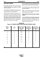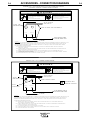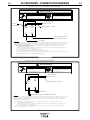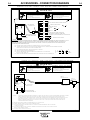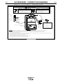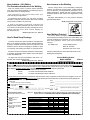
1
RETURN TO MAIN MENU
IM606
Ranger 275
For use with machines having Code Numbers:
July, 2001
10543
Safety Depends on You
Lincoln arc welding and cutting
equipment is designed and built
with safety in mind. However, your
overall safety can be increased by
proper installation ... and thoughtful operation on your part. DO
NOT INSTALL, OPERATE OR
REPAIR THIS EQUIPMENT
WITHOUT READING THIS
MANUAL AND THE SAFETY
PRECAUTIONS CONTAINED
THROUGHOUT. And, most
importantly, think before you act
and be careful.
Date of Purchase:
Serial Number:
Code Number:
Model:
Where Purchased:
OPERATOR’S MANUAL
Copyright © 2001 Lincoln Global Inc.
• World's Leader in Welding and Cutting Products •
• Sales and Service through Subsidiaries and Distributors Worldwide •
Cleveland, Ohio 44117-1199 U.S.A. TEL: 216.481.8100 FAX: 216.486.1751 WEB SITE: www.lincolnelectric.com
i
i
SAFETY
WARNING
CALIFORNIA PROPOSITION 65 WARNINGS
Diesel engine exhaust and some of its constituents
are known to the State of California to cause cancer, birth defects, and other reproductive harm.
The Above For Diesel Engines
The engine exhaust from this product contains
chemicals known to the State of California to cause
cancer, birth defects, or other reproductive harm.
The Above For Gasoline Engines
ARC WELDING CAN BE HAZARDOUS. PROTECT YOURSELF AND OTHERS FROM POSSIBLE SERIOUS INJURY OR DEATH.
KEEP CHILDREN AWAY. PACEMAKER WEARERS SHOULD CONSULT WITH THEIR DOCTOR BEFORE OPERATING.
Read and understand the following safety highlights. For additional safety information, it is strongly recommended that you
purchase a copy of “Safety in Welding & Cutting - ANSI Standard Z49.1” from the American Welding Society, P.O. Box
351040, Miami, Florida 33135 or CSA Standard W117.2-1974. A Free copy of “Arc Welding Safety” booklet E205 is available
from the Lincoln Electric Company, 22801 St. Clair Avenue, Cleveland, Ohio 44117-1199.
BE SURE THAT ALL INSTALLATION, OPERATION, MAINTENANCE AND REPAIR PROCEDURES ARE
PERFORMED ONLY BY QUALIFIED INDIVIDUALS.
FOR ENGINE
powered equipment.
1.h. To avoid scalding, do not remove the
radiator pressure cap when the engine is
hot.
1.a. Turn the engine off before troubleshooting and maintenance
work unless the maintenance work requires it to be running.
____________________________________________________
1.b. Operate engines in open, well-ventilated
areas or vent the engine exhaust fumes
outdoors.
____________________________________________________
1.c. Do not add the fuel near an open flame
welding arc or when the engine is running.
Stop the engine and allow it to cool before
refueling to prevent spilled fuel from vaporizing on contact with hot engine parts and
igniting. Do not spill fuel when filling tank. If
fuel is spilled, wipe it up and do not start
engine until fumes have been eliminated.
____________________________________________________
1.d. Keep all equipment safety guards, covers and devices in
position and in good repair.Keep hands, hair, clothing and
tools away from V-belts, gears, fans and all other moving
parts when starting, operating or repairing equipment.
____________________________________________________
1.e. In some cases it may be necessary to remove safety
guards to perform required maintenance. Remove
guards only when necessary and replace them when the
maintenance requiring their removal is complete.
Always use the greatest care when working near moving
parts.
___________________________________________________
1.f. Do not put your hands near the engine fan.
Do not attempt to override the governor or
idler by pushing on the throttle control rods
while the engine is running.
ELECTRIC AND
MAGNETIC FIELDS
may be dangerous
2.a. Electric current flowing through any conductor causes
localized Electric and Magnetic Fields (EMF). Welding
current creates EMF fields around welding cables and
welding machines
2.b. EMF fields may interfere with some pacemakers, and
welders having a pacemaker should consult their physician
before welding.
2.c. Exposure to EMF fields in welding may have other health
effects which are now not known.
2.d. All welders should use the following procedures in order to
minimize exposure to EMF fields from the welding circuit:
2.d.1. Route the electrode and work cables together - Secure
them with tape when possible.
2.d.2. Never coil the electrode lead around your body.
2.d.3. Do not place your body between the electrode and
work cables. If the electrode cable is on your right
side, the work cable should also be on your right side.
2.d.4. Connect the work cable to the workpiece as close as
possible to the area being welded.
___________________________________________________
1.g. To prevent accidentally starting gasoline engines while
turning the engine or welding generator during maintenance
work, disconnect the spark plug wires, distributor cap or
magneto wire as appropriate.
2.d.5. Do not work next to welding power source.
Mar ‘95
ii
ii
SAFETY
ELECTRIC SHOCK can
kill.
3.a. The electrode and work (or ground) circuits
are electrically “hot” when the welder is on.
Do not touch these “hot” parts with your bare
skin or wet clothing. Wear dry, hole-free
gloves to insulate hands.
3.b. Insulate yourself from work and ground using dry insulation.
Make certain the insulation is large enough to cover your full
area of physical contact with work and ground.
In addition to the normal safety precautions, if welding
must be performed under electrically hazardous
conditions (in damp locations or while wearing wet
clothing; on metal structures such as floors, gratings or
scaffolds; when in cramped positions such as sitting,
kneeling or lying, if there is a high risk of unavoidable or
accidental contact with the workpiece or ground) use
the following equipment:
• Semiautomatic DC Constant Voltage (Wire) Welder.
• DC Manual (Stick) Welder.
• AC Welder with Reduced Voltage Control.
3.c. In semiautomatic or automatic wire welding, the electrode,
electrode reel, welding head, nozzle or semiautomatic
welding gun are also electrically “hot”.
3.d. Always be sure the work cable makes a good electrical
connection with the metal being welded. The connection
should be as close as possible to the area being welded.
3.e. Ground the work or metal to be welded to a good electrical
(earth) ground.
3.f. Maintain the electrode holder, work clamp, welding cable and
welding machine in good, safe operating condition. Replace
damaged insulation.
3.g. Never dip the electrode in water for cooling.
3.h. Never simultaneously touch electrically “hot” parts of
electrode holders connected to two welders because voltage
between the two can be the total of the open circuit voltage
of both welders.
3.i. When working above floor level, use a safety belt to protect
yourself from a fall should you get a shock.
3.j. Also see Items 6.c. and 8.
ARC RAYS can burn.
4.a. Use a shield with the proper filter and cover
plates to protect your eyes from sparks and
the rays of the arc when welding or observing
open arc welding. Headshield and filter lens
should conform to ANSI Z87. I standards.
4.b. Use suitable clothing made from durable flame-resistant
material to protect your skin and that of your helpers from
the arc rays.
4.c. Protect other nearby personnel with suitable, non-flammable
screening and/or warn them not to watch the arc nor expose
themselves to the arc rays or to hot spatter or metal.
FUMES AND GASES
can be dangerous.
5.a. Welding may produce fumes and gases
hazardous to health. Avoid breathing these
fumes and gases.When welding, keep
your head out of the fume. Use enough
ventilation and/or exhaust at the arc to keep
fumes and gases away from the breathing zone. When
welding with electrodes which require special
ventilation such as stainless or hard facing (see
instructions on container or MSDS) or on lead or
cadmium plated steel and other metals or coatings
which produce highly toxic fumes, keep exposure as
low as possible and below Threshold Limit Values (TLV)
using local exhaust or mechanical ventilation. In
confined spaces or in some circumstances, outdoors, a
respirator may be required. Additional precautions are
also required when welding on galvanized steel.
5.b. Do not weld in locations near chlorinated hydrocarbon vapors
coming from degreasing, cleaning or spraying operations.
The heat and rays of the arc can react with solvent vapors to
form phosgene, a highly toxic gas, and other irritating
products.
5.c. Shielding gases used for arc welding can displace air and
cause injury or death. Always use enough ventilation,
especially in confined areas, to insure breathing air is safe.
5.d. Read and understand the manufacturer’s instructions for this
equipment and the consumables to be used, including the
material safety data sheet (MSDS) and follow your
employer’s safety practices. MSDS forms are available from
your welding distributor or from the manufacturer.
5.e. Also see item 1.b.
Mar ‘95
iii
iii
SAFETY
WELDING SPARKS can
cause fire or explosion.
6.a. Remove fire hazards from the welding area.
If this is not possible, cover them to prevent
the welding sparks from starting a fire.
Remember that welding sparks and hot
materials from welding can easily go through small cracks
and openings to adjacent areas. Avoid welding near
hydraulic lines. Have a fire extinguisher readily available.
6.b. Where compressed gases are to be used at the job site,
special precautions should be used to prevent hazardous
situations. Refer to “Safety in Welding and Cutting” (ANSI
Standard Z49.1) and the operating information for the
equipment being used.
6.c. When not welding, make certain no part of the electrode
circuit is touching the work or ground. Accidental contact
can cause overheating and create a fire hazard.
6.d. Do not heat, cut or weld tanks, drums or containers until the
proper steps have been taken to insure that such procedures
will not cause flammable or toxic vapors from substances
inside. They can cause an explosion even though they have
been “cleaned”. For information, purchase “Recommended
Safe Practices for the Preparation for Welding and Cutting of
Containers and Piping That Have Held Hazardous
Substances”, AWS F4.1 from the American Welding Society
(see address above).
6.e. Vent hollow castings or containers before heating, cutting or
welding. They may explode.
6.f. Sparks and spatter are thrown from the welding arc. Wear oil
free protective garments such as leather gloves, heavy shirt,
cuffless trousers, high shoes and a cap over your hair. Wear
ear plugs when welding out of position or in confined places.
Always wear safety glasses with side shields when in a
welding area.
6.g. Connect the work cable to the work as close to the welding
area as practical. Work cables connected to the building
framework or other locations away from the welding area
increase the possibility of the welding current passing
through lifting chains, crane cables or other alternate circuits. This can create fire hazards or overheat lifting chains
or cables until they fail.
6.h. Also see item 1.c.
CYLINDER may explode
if damaged.
7.a. Use only compressed gas cylinders
containing the correct shielding gas for the
process used and properly operating
regulators designed for the gas and
pressure used. All hoses, fittings, etc. should be suitable for
the application and maintained in good condition.
7.b. Always keep cylinders in an upright position securely
chained to an undercarriage or fixed support.
7.c. Cylinders should be located:
• Away from areas where they may be struck or subjected to
physical damage.
• A safe distance from arc welding or cutting operations and
any other source of heat, sparks, or flame.
7.d. Never allow the electrode, electrode holder or any other
electrically “hot” parts to touch a cylinder.
7.e. Keep your head and face away from the cylinder valve outlet
when opening the cylinder valve.
7.f. Valve protection caps should always be in place and hand
tight except when the cylinder is in use or connected for
use.
7.g. Read and follow the instructions on compressed gas
cylinders, associated equipment, and CGA publication P-l,
“Precautions for Safe Handling of Compressed Gases in
Cylinders,” available from the Compressed Gas Association
1235 Jefferson Davis Highway, Arlington, VA 22202.
FOR ELECTRICALLY
powered equipment.
8.a. Turn off input power using the disconnect
switch at the fuse box before working on
the equipment.
8.b. Install equipment in accordance with the U.S. National
Electrical Code, all local codes and the manufacturer’s
recommendations.
8.c. Ground the equipment in accordance with the U.S. National
Electrical Code and the manufacturer’s recommendations.
Mar ‘95
iv
iv
SAFETY
PRÉCAUTIONS DE SÛRETÉ
Pour votre propre protection lire et observer toutes les instructions
et les précautions de sûreté specifiques qui parraissent dans ce
manuel aussi bien que les précautions de sûreté générales suivantes:
Sûreté Pour Soudage A L’Arc
1. Protegez-vous contre la secousse électrique:
a. Les circuits à l’électrode et à la piéce sont sous tension
quand la machine à souder est en marche. Eviter toujours
tout contact entre les parties sous tension et la peau nue
ou les vétements mouillés. Porter des gants secs et sans
trous pour isoler les mains.
b. Faire trés attention de bien s’isoler de la masse quand on
soude dans des endroits humides, ou sur un plancher
metallique ou des grilles metalliques, principalement dans
les positions assis ou couché pour lesquelles une grande
partie du corps peut être en contact avec la masse.
c. Maintenir le porte-électrode, la pince de masse, le câble
de soudage et la machine à souder en bon et sûr état
defonctionnement.
d.Ne jamais plonger le porte-électrode dans l’eau pour le
refroidir.
e. Ne jamais toucher simultanément les parties sous tension
des porte-électrodes connectés à deux machines à souder
parce que la tension entre les deux pinces peut être le
total de la tension à vide des deux machines.
f. Si on utilise la machine à souder comme une source de
courant pour soudage semi-automatique, ces precautions
pour le porte-électrode s’applicuent aussi au pistolet de
soudage.
2. Dans le cas de travail au dessus du niveau du sol, se protéger
contre les chutes dans le cas ou on recoit un choc. Ne jamais
enrouler le câble-électrode autour de n’importe quelle partie
du corps.
3. Un coup d’arc peut être plus sévère qu’un coup de soliel,
donc:
a. Utiliser un bon masque avec un verre filtrant approprié
ainsi qu’un verre blanc afin de se protéger les yeux du rayonnement de l’arc et des projections quand on soude ou
quand on regarde l’arc.
b. Porter des vêtements convenables afin de protéger la
peau de soudeur et des aides contre le rayonnement de
l‘arc.
c. Protéger l’autre personnel travaillant à proximité au
soudage à l’aide d’écrans appropriés et non-inflammables.
4. Des gouttes de laitier en fusion sont émises de l’arc de
soudage. Se protéger avec des vêtements de protection libres
de l’huile, tels que les gants en cuir, chemise épaisse, pantalons sans revers, et chaussures montantes.
5. Toujours porter des lunettes de sécurité dans la zone de
soudage. Utiliser des lunettes avec écrans lateraux dans les
zones où l’on pique le laitier.
6. Eloigner les matériaux inflammables ou les recouvrir afin de
prévenir tout risque d’incendie dû aux étincelles.
7. Quand on ne soude pas, poser la pince à une endroit isolé de
la masse. Un court-circuit accidental peut provoquer un
échauffement et un risque d’incendie.
8. S’assurer que la masse est connectée le plus prés possible
de la zone de travail qu’il est pratique de le faire. Si on place
la masse sur la charpente de la construction ou d’autres
endroits éloignés de la zone de travail, on augmente le risque
de voir passer le courant de soudage par les chaines de levage, câbles de grue, ou autres circuits. Cela peut provoquer
des risques d’incendie ou d’echauffement des chaines et des
câbles jusqu’à ce qu’ils se rompent.
9. Assurer une ventilation suffisante dans la zone de soudage.
Ceci est particuliérement important pour le soudage de tôles
galvanisées plombées, ou cadmiées ou tout autre métal qui
produit des fumeés toxiques.
10. Ne pas souder en présence de vapeurs de chlore provenant
d’opérations de dégraissage, nettoyage ou pistolage. La
chaleur ou les rayons de l’arc peuvent réagir avec les vapeurs
du solvant pour produire du phosgéne (gas fortement toxique)
ou autres produits irritants.
11. Pour obtenir de plus amples renseignements sur la sûreté,
voir le code “Code for safety in welding and cutting” CSA
Standard W 117.2-1974.
PRÉCAUTIONS DE SÛRETÉ POUR
LES MACHINES À SOUDER À
TRANSFORMATEUR ET À
REDRESSEUR
1. Relier à la terre le chassis du poste conformement au code de
l’électricité et aux recommendations du fabricant. Le dispositif
de montage ou la piece à souder doit être branché à une
bonne mise à la terre.
2. Autant que possible, I’installation et l’entretien du poste seront
effectués par un électricien qualifié.
3. Avant de faires des travaux à l’interieur de poste, la debrancher à l’interrupteur à la boite de fusibles.
4. Garder tous les couvercles et dispositifs de sûreté à leur
place.
Mar. ‘93
v
v
Thank You
for selecting this QUALITY product. We want you to take pride in
operating this product ••• as much pride as we have in bringing
this product to you!
Please Examine Carton and Equipment For Damage Immediately
When this equipment is shipped, title passes to the purchaser upon receipt by the carrier. Consequently, Claims
for material damaged in shipment must be made by the purchaser against the transportation company at the
time the shipment is received.
Please record your equipment identification information below for future reference. This information can be
found on your machine nameplate.
Model Name & Number _____________________________________
Code & Serial Number _____________________________________
Date of Purchase
_____________________________________
Whenever you request replacement parts for or information on this equipment always supply the information
you have recorded above.
Read this Operators Manual completely before attempting to use this equipment. Save this manual and keep it
handy for quick reference. Pay particular attention to the safety instructions we have provided for your protection.
The level of seriousness to be applied to each is explained below:
WARNING
This statement appears where the information must be followed exactly to avoid serious personal injury or
loss of life.
CAUTION
This statement appears where the information must be followed to avoid minor personal injury or damage to
this equipment.
vi
TABLE OF CONTENTS
Page
Installation.......................................................................................................................Section A
Technical Specifications .......................................................................................................A-1
Installation Instructions. ........................................................................................................A-3
Location and Ventilation ................................................................................................A-3
Storing ...........................................................................................................................A-3
Stacking ........................................................................................................................A-3
Angle of Operation ........................................................................................................A-3
High Altitude Operation .................................................................................................A-4
Lifting.............................................................................................................................A-4
Additional Safety Precautions .......................................................................................A-4
Pre-Operation Engine Service..............................................................................................A-4
Oil ..................................................................................................................................A-4
Fuel ...............................................................................................................................A-5
Battery Connections ......................................................................................................A-5
Muffler ...........................................................................................................................A-5
Spark Arrester ...............................................................................................................A-5
Electrical Connections ..........................................................................................................A-6
Machine Grounding .......................................................................................................A-6
Welding Cable Connections ..........................................................................................A-6
Auxiliary Power Receptacles, Plugs, and Hand-Held Equipment ........................................A-7
Circuit Breakers ....................................................................................................................A-7
Premises Wiring ...................................................................................................................A-7
Operation.........................................................................................................................Section B
General Description..............................................................................................................B-1
Design Features ...................................................................................................................B-1
Other Features .....................................................................................................................B-2
Recommended Applications.................................................................................................B-2
Limitations ............................................................................................................................B-2
Additional Safety Precautions .............................................................................................B-2
Controls and Settings ..................................................................................................................B-3
Welder / Generator Controls .........................................................................................B-3
Engine Operation .................................................................................................................B-4
Before Starting the Engine ............................................................................................B-4
Starting the Engine........................................................................................................B-4
Stoping the Engine ........................................................................................................B-5
Fuel Consumption Data ................................................................................................B-5
Welding Operation................................................................................................................B-6
Welder Controls - Function and Operation....................................................................B-6
Stick Welding ................................................................................................................B-7
Pipe Welding .................................................................................................................B-7
TIG Welding ..................................................................................................................B-7
Wire Welding .................................................................................................................B-8
Summary of Welding Processes and Machine Settings ...............................................B-9
Auxiliary Power...................................................................................................................B-10
Simultaneous Welding and Power Loads ...................................................................B-10
Accessories .....................................................................................................Section C
General Options / Accessories ..............................................................................C-1
TIG Welding Options / Accessories.......................................................................C-1
Semiautomatic FCAW and MIG Welding Options / Accessories.........................................C-2
Connection Diagrams for Accessories ..................................................................C-3
vii
TABLE OF CONTENTS
Page
Maintenance ....................................................................................................Section D
Safety Precautions ................................................................................................D-1
Routine and Periodic Engine Maintenance ...........................................................D-1
Engine Maintenance Parts..............................................................................D-1
Engine Maintenance Schedule .......................................................................D-2
Changing the Engine Oil .................................................................................D-3
Changing the Engine Oil Filter ........................................................................D-3
Air Cleaner Service .........................................................................................D-3
Spark Plug Service .........................................................................................D-4
Fuel Filter Service ...........................................................................................D-5
Engine Adjustments ........................................................................................D-5
Battery Maintenance .......................................................................................D-5
Servicing Optional Spark Arrestor .........................................................................D-6
Welder / Generator Maintenance ..........................................................................D-6
Storage ...........................................................................................................D-6
Cleaning..........................................................................................................D-6
Brush Removal and Replacement ..................................................................D-6
Troubleshooting ..............................................................................................Section E
Safety Precautions.................................................................................................E-1
How to Use Troubleshooting Guide.......................................................................E-1
Troubleshooting Guide ..........................................................................................E-2
Wiring Diagram & Dimension Print................................................................Section F
Parts Lists ....................................................................................................P330 Series
A-1
A-1
INSTALLATION
TECHNICAL SPECIFICATIONS - Ranger 275 Kohler Engine (K1641-1)
INPUT - ENGINE
Make/Model
Description
Speed (RPM)
Displacement
Starting
System
Kohler
2 cylinder
20.0 HP @
3600 RPM
Full Load
High Idle 3700
Low Idle 2400
Full Load 3400
38 cu. in(624 cc)
12VDC battery
Fuel: 9.0 gal.
(Group 58, 435
(34 L)
cold crank amps)
CH20
Bore x Stroke
3.03” x 2.64”
Gas Engine
Capacities
25 A. Alternator
(77 mm x 67 mm)
Oil: 2.0 Qts.
(1.9 L)
RATED OUTPUT - WELDER
Welding Output
Volts at Rated Amps
Duty Cycle1
Max. OCV @ 3700 RPM
28 volts
25 volts
100%
60%
80 volts DC
CC Stick/TIG, Pipe and CV Wire Welding
275 Amps
300 Amps
OUTPUT - GENERATOR
Auxiliary Power 2
9,000 Watts, 60 Hz
120/240 Volts
100 % Duty Cycle
115/42 Volt Auxiliary Power for Wire Feeders
PHYSICAL DIMENSIONS
HEIGHT
WIDTH
DEPTH
WEIGHT
30.3 in.
19.1 in.
42.0 in.
469 lbs.
770 mm
485 mm
1067 mm
212 kg.
1. Duty cycle is based on a 10 minute period. This machine can be loaded to 300 amps for 6 minutes out of every 10 minute
period.
2. Output rating in watts is equivalent to volt-amperes at unity power factor. Output voltage is within ± 10% at all loads up to
rated capacity. When welding, available auxiliary power will be reduced.
RANGER 275
A-2
INSTALLATION
TECHNICAL SPECIFICATIONS - Ranger 275 (K1641-1)
RANGER 275
A-2
A-3
INSTALLATION
A-3
Always operate the Ranger 275 with the case roof on
and all machine components completely assembled.
This will protect you from the dangers of moving parts,
hot metal surfaces, and live electrical devices.
INSTALLATION INSTRUCTIONS
SAFETY PRECAUTIONS
WARNING
STORING
Do not attempt to use this equipment until you
have thoroughly read the engine manufacturer’s
manual supplied with your welder. It includes
important safety precautions, detailed engine
starting, operating and maintenance instructions,
and parts lists.
-----------------------------------------------------------------------ELECTRIC SHOCK can kill.
• Do not touch electrically live parts or
electrode with skin or wet clothing.
• Insulate yourself from work and
ground
• Always wear dry insulating gloves.
-----------------------------------------------------------------------ENGINE EXHAUST can kill.
• Use in open, well ventilated areas or
vent exhaust outside.
1. Store the machine in a cool, dry place when it is
not in use. Protect it from dust and dirt. Keep it
where it can’t be accidentally damaged from construction activities, moving vehicles, and other
hazards.
2. Drain the engine oil and refill with fresh oil. Run
the engine for about five minutes to circulate oil to
all the parts. See the MAINTENANCE section of
this manual for details on changing oil.
3. Remove the battery, recharge it, and adjust the
electrolyte level. Store the battery in a dry, dark
place.
-----------------------------------------------------------------------MOVING PARTS can injure.
• Do not operate with doors open or
guards off.
• Stop engine before servicing.
• Keep away from moving parts.
------------------------------------------------------------------------
STACKING
See additional warning information at
front of this operator’s manual.
-----------------------------------------------------------
Place the machine on a secure, level surface whenever you use it or store it. Any surfaces you place it on
other than the ground must be firm, non-skid, and
structurally sound.
Only qualified personnel should install,
use, or service this equipment.
LOCATION AND VENTILATION
Whenever you use the Ranger 275, be sure that clean
cooling air can flow through the machine’s engine and
the machine case. Avoid dusty, dirty areas. Also,
keep the machine away from heat sources. Do not
place the engine end of the machine anywhere near
hot engine exhaust from another machine or closer
than two feet from a wall. And of course, make sure
that engine exhaust is ventilated to an open, outside
area.
Ranger 275 machines CANNOT be stacked.
ANGLE OF OPERATION
The engine is designed to run in a level position for
best performance. It can operate at an angle, but this
should never be more than 15 degrees in any direction. If you do operate it at a slight angle, be sure to
check the oil regularly and keep the oil level at the
FULL mark as it would be in its normal level condition.
Also, fuel capacity will be a little less at an angle.
The Ranger 275 may be used outdoors. Do not set
the machine in puddles or otherwise submerge it in
water. Such practices pose safety hazards and cause
improper operation and corrosion of parts.
RANGER 275
A-4
A-4
INSTALLATION
HIGH ALTITUDE OPERATION
PRE-OPERATION ENGINE SERVICE
At high altitude, the standard carburetor air-fuel mixture will be too rich. Performance will decrease, and
fuel consumption will increase. A very rich mixture will
also foul the spark plug and cause hard starting.
High altitude performance can be improved by specific
modifications to the carburetor. If you always operate
your engine at altitudes above (6,000 feet) 1,800
meters, have a engine dealer perform this carburetor
modification.
Even with carburetor modification, engine horsepower
will decrease about 3.5% for each 1,000 feet (300
meter) increase in altitude. The effect of altitude on
horsepower will be greater than this if no carburetor
modification is made. Do not operate a modified
engine below 6,000 feet.
CAUTION
READ and UNDERSTAND the engine operating and
maintenance instructions supplied with this machine.
------------------------------------------------------------------------
WARNING
• Keep hands way from the engine muffler or HOT
engine parts.
• Stop the engine when fueling.
• Do not smoke when fueling.
• Do not overfill the fuel tank.
• Wipe up spilled fuel and allow the fumes to clear
before starting the engine.
LIFTING
The Ranger 275 weighs approximately 469 lbs/212
kg. A lift bail is mounted to the machine frame and
should always be used when lifting the machine.
• Keep sparks and flame away from the fuel tank.
------------------------------------------------------------------------
OIL
ADDITIONAL SAFETY PRECAUTIONS
WARNING
●
●
FALLING EQUIPMENT can cause
injury.
● Do not lift this machine using lift
bale if it is equipped with a heavy
accessory such as trailer or gas
cylinder.
Lift only with equipment of adequate lifting
capacity.
Be sure machine is stable when lifting.
The Ranger 275 is shipped with the engine filled with
SAE 10W-30 oil. CHECK THE OIL LEVEL BEFORE
YOU START THE ENGINE. If it is not full, add
enough oil to fill it to the full mark.
For more information on oil viscosity and service conditions, see the MAINTENANCE section of this manual and the engine Operator’s Manual.
RANGER 275
A-5
FUEL
IMPORTANT: To prevent ELECTRICAL DAMAGE
WHEN:
Fill the fuel tank with clean, fresh regular grade leadfree gasoline. Observe the fuel gauge while filling to
prevent overfilling.
The Ranger 275 has a 9 U.S. gallon (7.5 Imp. Gal.,
34L) fuel tank mounted below the generator. See the
Engine Owners Manual for more details about the
fuel.
a) Installing new batteries.
b) Using a booster.
Use correct polarity — Negative Ground.
The Ranger 275 is shipped with the negative battery
cable disconnected. Before you operate the machine,
make sure the Engine Switch is in the STOP position
and attach the disconnected cable securely to the
negative (-) battery terminal.
Remove the insulating cap from the negative battery
terminal. Replace and tighten negative battery cable
terminal. NOTE: This machine is furnished with a wet
charged battery; if unused for several months, the battery may require a booster charge. Be sure to use the
correct polarity when charging the battery.
BATTERY CONNECTIONS
WARNING
GASES FROM BATTERY can explode.
● Keep sparks, flame and cigarettes
away from battery.
To prevent EXPLOSION when:
● INSTALLING A NEW BATTERY — disconnect
negative cable from old battery first and connect
to new battery last.
● CONNECTING A BATTERY CHARGER —
remove battery from welder by disconnecting negative cable first, then positive cable and battery
clamp. When reinstalling, connect
negative cable last. Keep well ventilated.
●
A-5
INSTALLATION
USING A BOOSTER — connect positive lead to
battery first then connect negative lead to negative
battery lead at engine foot.
BATTERY ACID can burn eyes and
skin.
● Wear gloves and eye protection and
be careful when working near battery.
● Follow instructions printed on battery.
------------------------------------------------------------------------
MUFFLER
CAUTION
Shut off the machine and allow the muffler to cool
before touching the muffler.
-----------------------------------------------------------------------The Ranger 275 is shipped with the exhaust coming
out on the left side. The exhaust can be changed to
the opposite side by removing the two screws that
hold the exhaust port cover in place and installing the
cover on the opposite side. (Operating the Ranger
275 without the cover in place will result in a higher
noise level and no increase in machine output.)
SPARK ARRESTER
Gasoline engine mufflers may emit sparks when the
engine is running. Some federal, state, or local laws
require spark arresters in locations where unarrested
sparks could present a fire hazard.
Standard mufflers do not act as spark arresters.
When local laws require it, a spark arrester must be
installed on the machine and properly maintained. An
optional spark arrester kit is available for your Ranger
275. See the ACCESSORIES section of this manual
for more information.
CAUTION
An incorrect spark arrester may lead to damage to the
engine or reduce performance.
------------------------------------------------------------------------
RANGER 275
A-6
A-6
INSTALLATION
ELECTRICAL CONNECTIONS
TOTAL COMBINED LENGTH OF
ELECTRODE AND WORK CABLES
See Figure B.1 in the OPERATION section of this
manual for location of the 120 and 240 volt receptacles, weld output terminals, circuit breakers and
ground stud.
Cable Length
0-50 Ft. (0-15 meters)
Cable Size for
300 Amps
100% Duty Cycle
1/0 AWG
MACHINE GROUNDING
Because the Ranger 275 creates its own power from
its engine driven generator, and if the machine is not
connected to premises wiring (home, shop, etc.), you
do not need to connect the machine frame to an earth
ground. However, for best protection against electrical shock, connect a heavy gauge wire (#8 AWG or
larger) from the ground stud located on the bottom of
the output panel (See Figure B.1) to a suitable earth
ground such as a metal pipe driven into the ground.
50-100 Ft. (15-39 meters)
1/0 AWG
100-150 Ft. (30-46 meters)
2/0 AWG
150-200 Ft. (46-61 meters)
2/0 AWG
200-250 Ft. (61-76 meters)
3/0 AWG
Table A.1
CABLE INSTALLATION
WARNING
Do not ground the machine to a pipe that carries
explosive or combustible material.
-----------------------------------------------------------------------When the Ranger 275 is mounted on a truck or a trailer, the machine generator ground stud MUST be
securely connected to the metal frame of the vehicle.
See Figure B.1. The ground stud is marked with the
ground symbol.
If the Ranger 275 is connected to premises wiring
such as a home or shop, it must be properly connected to the system earth ground.
Install the welding cables to your Ranger 275 as follows. See Figure B.1 for location of parts.
1. The engine must be OFF to install welding cables.
2. Remove the flanged nuts from the output terminals.
3. Connect the electrode holder and work cables to
the weld “+” and “-” output terminals. The terminals
are identified on the case front. The polarity requirement for the welding process being used determines which terminal the electrode cable is
attached to.
4. Tighten the flanged nuts securely.
WELDING CABLE CONNECTIONS
5. Be certain that the metal piece you are welding (the
“work”) is properly connected to the work clamp and
cable.
CABLE SIZE AND LENGTH
Be sure to use welding cables that are large enough.
The correct size and length becomes especially
important when you are welding at a distance from the
welder.
Table A.1 lists recommended cable sizes and lengths
for rated current and duty cycle. Length refers to the
distance from the welder to the work and back to the
welder. Cable diameters are increased for long cable
lengths to reduce voltage drops.
Lincoln Electric offers a welding accessory kit with the
properly specified welding cables. See the
ACCESSORIES section of this manual for more information.
6. Check and tighten the connections periodically.
CAUTION
• Loose connections will cause the output terminals to
overheat. The terminals may eventually melt.
• Do not cross the welding cables at the output terminal connection. Keep the cables isolated and separate from one another.
------------------------------------------------------------------------
RANGER 275
A-7
A-7
INSTALLATION
AUXILIARY POWER RECEPTACLES,
PLUGS, AND HAND-HELD EQUIPMENT
The control panel of the Ranger 275 features three
auxiliary power receptacles: See Figure B.1.
• Two 15 amp, 120 volt duplex (double outlet) receptacles.
PREMISES WIRING
The Ranger 275 is suitable for temporary, standby, or
emergency power using the engine manufacturer’s
recommended maintenance schedule. With its threewire grounded neutral generator, it can be permanently installed as a standby power unit for 240 volt, three
wire, single phase 38 ampere service.
WARNING
• One 50 amp 120/240 volt single outlet receptacle.
Through these receptacles the machine can supply up
to 9,000 rated continuous watts of single-phase, 60
Hz AC power.
Only a licensed, certified, trained electrician should
install the machine to a premises or residential electrical system. Be certain that:
For further protection against electric shock, any electrical equipment connected to the 120V duplex receptacles must use a three-blade, grounded type plug or
an Underwriter’s Laboratories (UL) approved double
insulation system with a two-blade plug. Lincoln
offers an accessory plug kit that has the right type of
plugs. See the ACCESSORIES section of this manual
for more information.
• The installation complies with the National Electrical
Code and all other applicable electrical codes.
If you need ground fault protection for hand-held
equipment refer to the K896-1 GFCI Receptacle kit in
the ACCESSORIES section of this manual for more
information.
• A double pole, double throw transfer switch in conjunction with the properly rated double throw circuit
breaker is connected between the generator power
and the utility meter.
-----------------------------------------------------------------------The following information and the connection diagram,
Figure A.1, can be used as a guide by the electrician
for most applications to premises wiring.
For recommended extension cord lengths and sizes
see Table A.1.
CIRCUIT BREAKERS
The Ranger 275 machines are equipped with 50 amp
circuit breakers on the 120/240 V receptacle and 15
amp circuit breakers on the 120 receptacles for overload protection. Under high heat a breaker may tend
to trip at lower loads than it would normally.
CAUTION
Never bypass the circuit breakers. Without overload
protection, the Ranger 275 could overheat and/or
cause damage to the equipment being used.
------------------------------------------------------------------------
• The premises is isolated and no feedbacking into
the utility system can occur. Certain state and local
laws require the premises to be isolated before the
generator is linked to the premises. Check your
state and local requirements.
1. Install a double pole, double throw switch between
the power company meter and the premises disconnect. The switch rating must be the same as
or greater than the premises disconnect and
service overcurrent protection.
2. Take the necessary steps to assure that the load is
limited to the capacity of the Ranger 275 by
installing a 40 amp 240 volt double pole circuit
breaker. Maximum rated load for the 240 volt auxiliary is 38 amperes. Loading above 38 amperes will
reduce output voltage below the allowable -10% of
rated voltage. This may damage appliances or
other motor-driven equipment.
3. Install a 50 amp 120/240 volt plug (NEMA type 1450) to the double pole circuit breaker using No. 8 or
larger, 4 conductor cable of the desired length.
(The 50 amp 120/240 volt plug is available in the
optional power plug kit.
4. Plug this cable in to the 50 amp 120/240 volt receptacle on the Ranger 275 case front.
RANGER 275
A-8
A-8
INSTALLATION
Table A.1
Extension Cord Length Recommendations
Current
Voltage
Load
(Amps)
15
15
20
25
30
38
(Volts)
120
240
240
240
240
240
(Watts)
1800
3600
4800
600
7200
9000
Maximum Allowable Cord Length in ft (m) for Conductor Size (AWG)
14 AWG
30
60
(9)
(18)
12 AWG
40
(12)
75
(23)
60
(18)
10 AWG
75
150
100
90
75
(23)
(46)
(30)
(27)
(23)
8 AWG
125
225
175
150
120
100
(38)
(69)
(53)
(46)
(37)
(30)
6 AWG
175
350
275
225
175
150
(53)
(107)
(84)
(69)
(53)
(46)
4 AWG
300
600
450
250
300
250
(91)
(183)
(137)
(76)
(91)
(76)
Figure A.1
CONNECTION OF Ranger 275 TO PREMISES WIRING
240 VOLT
GROUNDED CONDUCTOR
POWER
240 Volt
60 Hz.
3-Wire
Service
120 VOLT
COMPANY
120 VOLT
METER
NEUTRAL
BUS
N
LOAD
DOUBLE POLE DOUBLE THROW
SWITCH RATING TO BE THE SAME
AS OR GREATER THAN PREMISES
SERVICE OVERCURRENT
PROTECTION.
GROUND
40 AMP
240 VOLT
50 AMP, 120/240
VOLT PLUG
NEMA TYPE 14-50
240 VOLT
PREMISES
DISCONNECT AND
SERVICE
OVERCURRENT
PROTECTION
DOUBLE
POLE
CIRCUIT
BREAKER
GND
N
50 AMP, 120/240 VOLT
RECEPTACLE
NOTE: No. 8 COPPER CONDUCTOR CABLE SEE
NATIONAL ELECTRICAL CODE FOR ALTERNATE WIRE
SIZE RECOMMENDATIONS.
WARNING
Connection of Ranger 275 to premises wiring must be done by a licensed electrician and must comply
with the National Electrical Code and all other applicable electrical codes.
RANGER 275
B-1
OPERATION
B-1
OPERATING INSTRUCTIONS
GENERAL DESCRIPTION
Read and understand this entire section before operating your Ranger 275.
The Ranger 275 is an engine driven, multi-process
DC arc welder and AC power generator for commercial and residential applications. As a generator it can
supply up to 9,000 continuous watts of 120/240 volt,
60 Hz, single-phase AC power to operate AC power
tools, battery chargers, and lighting; it can also be
used to provide standby power. As a welder it provides up to 300 amps of DC current for DC stick welding and DC semiautomatic wire feed welding. The
Ranger 275 can also perform DC TIG welding.
SAFETY INSTRUCTIONS
WARNING
Do not attempt to use this equipment until you have
thoroughly read all operating and maintenance manuals supplied with your machine. They include important safety precautions, detailed engine starting,
operating and maintenance instructions and parts
lists.
ELECTRIC SHOCK can kill.
•Do not touch electrically live parts such
as output terminals or internal wiring.
•Insulate yourself from the work and
ground.
•Always wear dry insulating gloves.
-----------------------------------------------------------------------ENGINE EXHAUST can kill.
•Use in open, well ventilated areas or
vent exhaust outside
•Do not stack anything near the engine.
------------------------------------------------------------------------
DESIGN FEATURES
FOR WELDING:
• DC constant current output for stick and TIG welding - Two continuous CC output settings of 20 to
300 amps, one for general purpose stick and tig
welding and one with a fixed controlled slope for out
of position and pipe welding. The STICK-TIG mode
includes an arc force control.
• DC constant voltage output for MIG and Flux Cored
wire welding - One continuous CV welding range of
11 to 32 volts. Excellent MIG welding with CO2 and
blended gas. A pinch control allows the arc to be
fine tuned from “soft “ to “crisp”. The recommended
wire feeder is the K446 LN-25 with the K624-1 42
Volt Remote Output Control Module or the K449 LN25 with an internal contactor.
• 100% duty cycle at 275 amps output.
• Remote control capability. Nine pin and fourteen
pin connectors for easy connection of Lincoln wire
feeders and remote control accessories. The 14 pin
connector includes power for 42 VAC wire feeders.
MOVING PARTS can injure.
•Do not operate with doors open or
guards off.
• Internal “Solid State” contactor allows for the selection of “hot” or “cold” output terminals.
•Stop engine before servicing.
•Keep away from moving parts
-----------------------------------------------------------------------Only qualified personnel should operate this equipment.
FOR AUXILIARY POWER
• 9,000 watts of 240 V AC, 60Hz auxiliary power.
• Power for tools, 120/240 lights, electric pumps and
for standby emergency power.
• Power a 5 HP motor (provided it is started under no
load).
• Two 15 amp industrial grade 120 V AC duplex
receptacles for up to 60 amps of 120 VAC power.
RANGER 275
B-2
OPERATION
• One 50 amp 120 V single phase AC dual voltage
power receptacle with two 50 amp circuit breakers.
Supplies up to 38 amps of 240 V AC and up to 76
amps of 120 V AC single phase auxiliary power per
side to separate branch circuits (not in parallel).
Allows easy connection to premises wiring.
• Welding and AC auxiliary power at the same time
(within machine total capacity).
OTHER FEATURES
• Overhead valve, V-twin, 20 HP gasoline engine.
Designed for long life, easy maintenance and excellent fuel economy.
• Engine protection system shuts the engine down
with low oil pressure.
B-2
LIMITATIONS
• The Ranger 275 is not recommended for any
processes besides those that are normally performed using stick welding (SMAW), TIG welding
(GTAW), MIG (GMAW) welding and Innershield®
(FCAW) welding.
• The Ranger 275 is not recommended for pipe
thawing.
• During welding, generator power is limited and output voltages can drop. Therefore, DO NOT OPERATE ANY SENSITIVE ELECTRICAL EQUIPMENT
WHILE YOU ARE WELDING. See Table B.4 for
permissible simultaneous welding and auxiliary
power loads.
• Large maintenance-free battery. Group 58 with 435
cold cranking amps.
ADDITIONAL SAFETY PRECAUTIONS
• Battery charging ammeter.
• Engine hour meter.
• Extended range 9 U.S. gallon (7.5 Imp. Gal., 34
liters) fuel tank.
Always operate the welder with the roof and case
sides in place as this provides maximum protection
from moving parts and assures proper cooling air flow.
• Automatic idler reduces engine speed when not
welding or drawing auxiliary power. This feature
reduces fuel consumption and extends engine life.
Read and understand all Safety Precautions before
operating this machine. Always follow these and any
other safety procedures included in this manual and in
the Engine Owner’s Manual.
• Compact size fits crosswise in compact size pick-up
truck.
Only qualified personnel should install, use, or service
this equipment.
• Copper alternator windings for dependability and
long life.
• CSA approved.
RECOMMENDED APPLICATIONS
WELDER
The Ranger 275 provides excellent constant current
DC welding output for stick (SMAW) welding and for
TIG welding, and it offers constant voltage output for
DC semiautomatic wire feed welding.
GENERATOR
The Ranger 275 gives AC power output for medium
use demands.
RANGER 275
B-3
OPERATION
CONTROLS AND SETTINGS
All generator/welder controls are located on the
Output Control Panel of the machine case front. Idler
control, and start/stop controls are also on the case
front. See Figure B.1 and the explanations that follow.
5
4
15
3
17
B-3
put contactor. With the switch in the “CONTACTOR
ON” position, the contactor is closed at low and high
idle.
6. BATTERY CHARGER CIRCUIT BREAKER: Opens
the engine battery circuit if a short develops. Engine
will not crank if this circuit breaker is open.
7. WIRE FEEDER POWER CIRCUIT BREAKER: Opens
the wire feeder circuit and disables the feeder if a fault
is detected in the circuit.
1
18
2
8. 15 AMP, 120 VOLT DUPLEX RECEPTACLES:
Connection point for supplying 120 volt power to operate one or more electrical devices.
16
6
8
9. 50 AMP, 120/240 VOLT RECEPTACLE: Connection
point for supplying 240 volt power to operate one
electrical device.
19
20
10. WELD OUTPUT TERMINALS WITH FLANGE NUT:
Provides the connection point for the electrode and
work cables.
7
9
11
11. GROUND STUD: Provides a connection point for
connecting the machine case to earth ground for the
safest grounding procedure.
12. 6 PIN AMPHENOL: For attaching optional remote
control equipment to the Ranger 275.
10
13
14
12
13. 14 PIN AMPHENOL: For attaching wire feeder control cables to the Ranger 275 (Includes contactor closure circuit, remote control circuit, wire feeder 115/42
volt power source).
FIGURE B.1
OUTPUT PANEL CONTROLS
14. WIRE FEEDER VOLTMETER POLARITY SWITCH:
matches polarity of wire feeder voltmeter to polarity
of electrode.
WELDER/GENERATOR CONTROLS
See Figure B.1 for the location of the following features:
1. OUTPUT CONTROL: Allows full range adjustment of
welding current or voltage.
2. ARC CONTROL: The “ARC CONTROL” is active in
two modes: “STICK/TIG” and “WIRE WELDING” with
different purposes in each mode.
3. MODE SWITCH: Selects three possible modes of
welding operation, 1.) CC Stick/TIG Welding, 2.) Pipe
Welding, and 3.) CV Wire Welding.
4. LOCAL/REMOTE CONTROL SWITCH: Allows the
operator to control welding output at the welding control panel or at a wire feeder, TIG amptrol, or a K857
remote control.
15. ENGINE RUN-STOP SWITCH: Energizes engine circuit.
16. ENGINE START PUSHBUTTON SWITCH:
Energizes starter solenoid contactor and fuel solenoid.
17. ENGINE CHOKE
18. AUTO IDLER SWITCH: In the “AUTO” mode, the
engine goes to low idle speed 12 seconds after a
welding or auxiliary power load is removed. Engine
goes to high speed when the load is re-applied.
19. BATTERY CHARGER AMMETER
20. ENGINE HOUR METER
5. CONTACTOR SWITCH: The toggle switch labeled
“WELDING ON” and “CONTACTOR CONTROLLED”
is used to control the operation of the solid state out-
RANGER 275
B-4
B-4
OPERATION
ENGINE OPERATION
STARTING THE ENGINE
CAUTION
WARNING
DO NOT RUN THE ENGINE AT EXCESSIVE
SPEEDS. The maximum allowable high idle speed
for the Ranger 275 is 3750 RPM, no load. Do NOT
adjust the governor screw on the engine. Severe personal injury and damage to the machine can result if it
is operated at speeds above the maximum rated
speed.
-----------------------------------------------------------------------Read and understand all safety instructions included
in the Engine Owner’s manual that is shipped with
your Ranger 275.
BEFORE STARTING THE ENGINE
Check the engine oil level:
1. Be sure the machine is on a level surface.
2. Remove the engine oil dipstick and wipe it with a
clean cloth. Reinsert the dipstick and check the
level on the dipstick.
3. Add oil (if necessary) to bring the level up to the full
mark. Do not overfill.
4. See Engine Owner’s Manual for specific oil recommendations.
Be sure all Pre-Operation Maintenance has been performed. See the INSTALLATION section.
Remove all loads connected to the AC power receptacles and the welder before starting the diesel engine.
-----------------------------------------------------------------------To start the engine, set the “IDLER” switch in the
“AUTO” (
/
) position. Pull the choke
control out.
Place the “Engine” Switch in the “RUN”
Position.
Push the “Start” button and crank the engine until it
starts. Release the button as soon as the engine
starts. After the engine has started, slowly return the
choke control to the full “in” position (choke open). In
the “AUTO” position, the engine will run at high idle for
10-14 seconds and then go to low idle. Allow the
engine to warm up by letting it run at low idle for a few
minutes.
At cold temperatures, it may be necessary to start the
engine in “HIGH” idle and allow it to run for several
minutes before using “AUTO” idle.
When starting a hot engine, it is not necessary to pull
the choke out but the engine will start faster if it is
pulled out. Push it in immediately after the engine
starts.
CAUTION
WARNING
Check and fill the engine fuel tank:
GASOLINE can cause fire or
explosion.
• Stop engine when fueling.
• Do not smoke when fueling.
• Do not overfill tank.
• Avoid contact with skin or breathing of vapor.
• Keep sparks and flame away from tank.
-----------------------------------------------------------------------1. Remove the fuel tank cap.
Operating the starter motor for more than 5 seconds
can damage the motor. If the engine fails to start,
release the switch and wait 10 seconds before operating the starter again. Do not push the “Start” button
while the engine is running because this can damage
the ring gear and/or starter motor.
-----------------------------------------------------------------------NOTE: When starting a Ranger 275 for the first time,
after an extended period of not operating, it will take
longer than normal because the fuel pump has to fill
the fuel line and carburetor.
2. Fill the tank approximately 4 inches (100 mm) from
the top of the filler neck to allow for fuel expansion
(observe the fuel gauge.) DO NOT FILL THE
TANK TO THE POINT OF OVERFLOW.
3. Replace the fuel tank cap and tighten securely.
4. See Engine Owner’s Manual for fuel recommendations.
RANGER 275
B-5
OPERATION
B-5
Stop the engine by placing the “Engine” switch in the
“STOP” position.
STOPPING THE ENGINE
Remove all welding and auxiliary power loads and
allow the engine to run at low idle speed for a few
minutes to cool the engine.
A fuel shut off valve is not required on the Ranger 275
because the fuel tank is mounted below the engine.
------------------------------------------------------------------------
TABLE B.1
TYPICAL Ranger 275 FUEL CONSUMPTION
K1641-1 Ranger 275 Kohler
Engine
Low Idle - No Load
2400 RPM
.40 US gallons/hour
(.34 Imp. gal./hr., 1.53 liters/hour)
High Idle - No Load
3700 RPM
.87 US gallons/hour
(.73 Imp. gal./hr., 3.30 liters/hour)
210 Amps @ 25 Volts
DC Weld Output
1.27 US gallons/hour
(1.06 Imp. gal./hr., 4.82 liters/hour)
250 Amps @ 25 Volts
DC Weld Output
1.37 US gallons/hour
(1.14 Imp. gal./hr., 5.17 liters/hour)
275 Amps @ 25 Volts
DC Weld Output
1.44 US gallons/hour
(1.20 Imp. gal./hr., 5.45 liters/hour)
275 Amps @ 28 Volts
DC Weld Output
1.53 US gallons/hour
(1.28 Imp. gal./hr., 5.80 liters/hour)
9,000 watts
Auxiliary Power
1.54 US gallons/hour
(1.28 Imp. gal./hr., 5.81 liters/hour)
RANGER 275
B-6
B-6
OPERATION
“ARC CONTROL”
WELDING OPERATION
WARNING
Do not attempt to use this equipment until you
have thoroughly read the engine manufacturer’s
manual supplied with your welder. It includes
important safety precautions, detailed engine
starting, operating and maintenance instructions,
and parts lists.
-----------------------------------------------------------------------ELECTRIC SHOCK can kill.
• Do not touch electrically live parts or
electrode with skin or wet clothing.
• Insulate yourself from work and
ground
• Always wear dry insulating gloves.
-----------------------------------------------------------------------FUMES AND GASES can be dangerous.
• Keep your head out of fumes.
• Use ventilation or exhaust to remove
fumes from breathing zone.
-----------------------------------------------------------------------MOVING PARTS can injure.
• Do not operate with doors open or
guards off.
• Stop engine before servicing.
• Keep away from moving parts.
-----------------------------------------------------------------------WELDING SPARKS can cause fire or
explosion.
• Keep flammable material away.
The “ARC CONTROL” is active in two modes:
“STICK/TIG” and “WIRE WELDING” and has different
purposes in each mode. It is not active in the “PIPE”
mode.
“STICK/TIG” mode: In this mode, the “ARC CONTROL” knob sets the short circuit (arc force) current
during stick welding. Increasing the number from 1 to
10 increases the short circuit current. This prevents
sticking of the electrode to the plate at low welding
current settings. This also increases spatter. It is recommended that the control is set to the minimum
number without electrode sticking.
“WIRE WELDING” mode: In this mode, increasing
the number from 1 to 10 changes the arc from soft
and washed in to crisp and narrow. It acts as an
inductance control. The proper setting depends on
the application and operator preference. In general,
Mig welding performs best in the “SOFT” range and
Innershield in the “CRISP” range.
“LOCAL”
/
“REMOTE” Switch
-----------------------------------------------------------------------ARC RAYS can burn.
• Wear eye, ear and body protection.
The toggle switch on the control panel labeled
“LOCAL/REMOTE” gives the operator the option of
controlling the output at the welder control panel or at
a wire feeder, TIG amptrol, or a K857 Remote Control
that is connected to either the 6 pin or 14 pin amphenol connector.
------------------------------------------------------------------------
For remote control the toggle switch is set in the
“REMOTE” position.
See additional warning information
throughout this operator’s manual.
-----------------------------------------------------------
WELDER CONTROLS - FUNCTION
AND OPERATION
See Figure B.1 for control locations.
Output “CONTROL”
Continuous CC welding current control from 20 amps
to 300 amps in the STICK/TIG and PIPE modes.
Continuous CV welding arc voltage control from 11
volts to 32 volts in the WIRE FEED mode.
For control at the welder control panel, the toggle
switch is set in the “LOCAL” position.
“CONTACTOR” Switch
The toggle switch on the control panel labeled
“WELDING ON” and “CONTACTOR CONTROLLED”,
is used to control the operation of the solid state contactor which allows for the selection of “Hot” or “Cold”
welding terminals.
With the switch in the “WELDING ON” position, the
contactor is closed and the welding terminals are
always “Hot.”
With the switch in the “CONTACTOR CONTROLLED”
position, the contactor operation is controlled by an
Amptrol, Arc Start Switch or some other type of triggering device through the use of a control cable connected to the 6 pin or 14 pin amphenol.
RANGER 275
B-7
OPERATION
When the triggering device is pressed the contactor is
closed and the welding terminals are “Hot.”
When the triggering device is released the contactor is
opened and the welding terminals are “Cold.”
“MODE” Switch - Set to the desired process:
STICK/TIG, PIPE, or WIRE FEED.
B-7
TIG WELDING
The Ranger 275 can be used in a wide variety of DC
Tungsten Inert Gas (TIG) welding applications. When
used with the K930-1 or -2 TIG module, ratings are
limited to 275A at a 60% duty cycle and 250A at a
80% duty cycle.
“WIRE FEEDER VOLTMETER” Switch - If
Ranger 275 settings when using the K930-1 or -2 Tig
Module:
using a wire feeder that has a voltmeter, set this
switch to match the polarity of the electrode.
a. Set the “MODE” Switch to the STICK/TIG setting.
STICK WELDING
b. Set the “IDLER” Switch to the “AUTO” position.
The Ranger 275 can be used with a broad range of
DC stick electrodes. The output “CONTROL” adjusts
the full range of 20 to 300 amps. Set the “ARC CONTROL” to low setting to minimize spatter. If sticking is
a problem, turn this control to a higher setting (clockwise). This will increase the short circuit current (arc
force).
c. Set the “LOCAL/REMOTE” switch to the
“REMOTE” position.
PIPE WELDING
d. Set the ”WELDING TERMINALS” switch to the
“WELDING TERMINALS REMOTELY CONTROLLED” position. This will keep the “Solid
State” contactor open and provide a “cold” electrode until the triggering device (Amptrol or Arc
Start Switch) is pressed.
e. Set the “ARC CONTROL” to minimum.
The “PIPE WELDING” mode is recommended for
manual vertical-down techniques on pipe joints using
EXX10 type electrodes. This slope controlled setting
allows the operator to control the welding current by
changing the arc length.
See Table B.2 for Typical Current Ranges for
Tungsten Electrodes.
The “ARC CONTROL” (arc force) is automatically
switched off in this mode.
RANGER 275
B-8
B-8
OPERATION
Table B.2 TYPICAL CURRENT RANGES
Tungsten
Electrode
Diameter
in. (mm)
DCEN (-)
DCEP (+)
1%, 2%
Thoriated
Tungsten
1%, 2%
Thoriated
Tungsten
(1)
FOR TUNGSTEN ELECTRODES
(2)
Approximate Argon Gas Flow Rate
C.F.H. (l/min.)
Stainless Steel
TIG TORCH
Nozzle
Size (4), (5)
0 .010
0.020
0.040
(.25)
(.50)
(1.0)
2-15
5-20
15-80
(3)
(3)
(3)
3-8
5-10
5-10
(2-4)
(3-5)
(3-5)
#4, #5, #6
1/16
(1.6)
70-150
10-20
9-13
(4-6)
#5, #6
3/32
1/8
(2.4)
(3.2)
150-250
250-400
15-30
25-40
11-15
11-15
(5-7)
(5-7)
#6, #7, #8
5/32
3/16
1/4
(4.0)
(4.8)
(6.4)
400-500
500-750
750-1000
40-55
55-80
80-125
13-17
18-22
23-27
(6-8)
(8-10)
(11-13)
#8, #10
(1) When used with argon gas. The current ranges shown must be reduced when using argon/helium or pure helium
shielding gases.
(2) Tungsten electrodes are classified as follows by the American Welding Society (AWS):
Pure
EWP
1% Thoriated
EWTh-1
2% Thoriated
EWTh-2
Though not yet recognized by the AWS, Ceriated Tungsten is now widely accepted as a substitute for 2% Thoriated
Tungsten in AC and DC applications.
(3) DCEP is not commonly used in these sizes.
(4) TIG torch nozzle “sizes” are in multiples of 1/16ths of an inch:
# 4 = 1/4 in.
(6 mm)
# 5 = 5/16 in.
(8 mm)
# 6 = 3/8 in.
(10 mm)
# 7 = 7/16 in.
(11 mm)
# 8 = 1/2 in.
(12.5 mm)
#10 = 5/8 in.
(16 mm)
(5) TIG torch nozzles are typically made from alumina ceramic. Special applications may require lava nozzles, which are
less prone to breakage, but cannot withstand high temperatures and high duty cycles.
WIRE WELDING
Connect a wire feeder to the Ranger 275 and set
welder controls according to the instructions on the
appropriate wire feeder connection diagram.
The Ranger 275 in the ”WIRE FEED” position, permits
it to be used with a broad range of flux cored wire
(Innershield and Outershield) electrodes and solid
wires for MIG welding (gas metal arc welding).
Welding can be finely tuned using the “ARC CONTROL”.
Some recommended solid wires for MIG welding are:
.035 (0.9 mm) and .045 (1.1 mm) L-50, L-56, and
Blue Max MIG 308 LS.
For any electrodes, including the above recommendations, the procedures should be kept within the rating
of the machine. For additional electrode information,
see Lincoln publications N-675, GS-100 and GS-210.
Some recommended Innershield electrodes are: NR311, NS-3M, NR-207, NR-203 Ni 1%, NR-204-H.
Recommended Outershield electrodes are: 0S-70,
0S-71M.
RANGER 275
B-9
B-9
OPERATION
TABLE B.3
SUMMARY OF WELDING PROCESSES AND MACHINE SETTINGS
CONTROL
CABLE
USED
MODE
SWITCH
IDLER
SWITCH
NO
STICK/TIG
or PIPE
AUTO
LOCAL
WELDING
ON
HOT
YES
STICK/TIG
AUTO
REMOTE
CONTACTOR
CONTROLLED
COLD
YES
WIRE FEED
AUTO
REMOTE
CONTACTOR
CONTROLLED
COLD
NO
WIRE FEED
AUTO
LOCAL
WELDING
ON
COLD
WIRE FEED - CV,
LN-742
YES
WIRE FEED
AUTO
REMOTE
CONTACTOR
CONTROLLED
COLD
WIRE FEED - CV,
LN-7
YES
WIRE FEED
HIGH
REMOTE
CONTACTOR
CONTROLLED
COLD
PROCESS
STICK - CC
TIG - CC
K930-1 TIG MODULE /
K936-1 CONTROL CABLE
(With Amptrol)
WIRE FEED - CV,
LN-25 WITH 42V
REMOTE CONTROL KIT
WIRE FEED - CV,
LN-25 WITH
INTERNAL
CONTACTOR
OUTPUT CONTACTOR ELECTRODE
CONTROL SWITCH
WHEN NOT
SWITCH
WELDING
RANGER 275
TO START WELDING
Touch electrode to work.
Welding starts immediately
and engine goes to high idle.
Press Amptrol. Ranger 275
contactor closes. Welding
starts immediately and engine
goes to high idle.
Press gun trigger, Ranger
275 contactor closes.
Welding starts immediately
and engine goes to high idle.
Press gun trigger, LN-25
contactor closes. Welding
starts immediately and engine
goes to high idle.
Press gun trigger, Ranger
275 contactor closes.
Welding starts immediately
and engine goes to high idle.
Press gun trigger, Ranger
275 contactor closes.
Welding starts immediately.
B-10
B-10
OPERATION
The 120V duplex auxiliary power receptacles should
only be used with three wire grounded type plugs or
approved double insulated tools with two wire plugs.
AUXILIARY POWER
Start the engine and set the "IDLER" control switch to
the desired operating mode. Full power is available
regardless of the welding output settings, if no welding
current is being drawn.
The current rating of any plug used with the system
must be at least equal to the current capacity of the
associated receptacle.
The auxiliary power of the Ranger 275 consists of two
15 Amp-120VAC (5-15R) duplex receptacles and one
50 Amp 120/240 VAC (14-50R) receptacle.
NOTE: The 240V receptacle has two circuits, each of
which measure 120 V to neutral but are of opposite
polarities and cannot be paralleled.
The auxiliary power capacity is 9,000 watts of 60 Hz,
single phase power. The auxiliary power capacity rating in watts is equivalent to volt-amperes at unity
power factor. The max permissible current of the 240
VAC output is 38 Amps. The 240 VAC output can be
split to provide two separate 120 VAC outputs with a
max permissible current of 38 Amps per output to two
separate 120 VAC branch circuits. Output voltage is
within Å 10% at all loads up to rated capacity.
SIMULTANEOUS WELDING AND POWER
LOADS
It must be noted that the above auxiliary power ratings
are with no welding load. Simultaneous welding and
power loads are specified in the following table. The
permissible currents shown assume that current is
being drawn from either the 120 VAC or 240 VAC
supply (not both at the same time).
TABLE B.4
Ranger 275 SIMULTANEOUS WELDING AND POWER LOADS
Welding
Output
Amps
Arc
Voltage
Available Auxiliary
Power - Watts
(Unity Power
Factor)
Permissible
Auxiliary Current
in Amperes @
120V
Permissible
Auxiliary Current
in Amperes @
240V
0
0
9000
76
38
50
25
7400
62
31
100
25
6300
52
26
150
25
4800
40
20
200
25
3400
28
14
250
25
1800
15
7.5
275
25
1000
8
4
275
28
0
0
0
RANGER 275
C-1
ACCESSORIES
GENERAL OPTIONS /
ACCESSORIES
C-1
- GC500 work clamp.
- Cooltong® 300 insulated electrode holder.
The following options/accessories are available for
your Ranger 275:
K886-1 Canvas Cover - To protect the Ranger 275
when it is not being operated. Made from attractive
red canvas material that is flame retardant, mildew
resistant and water repellent.
K889-2 Two Wheel Undercarriage - For moving by
hand. Two 4.00" x 8" pneumatic tires. Overall width
29" (.74m).
K893-1 Caster for K889-2 Undercarriage - Mounts
to the front of the Two-Wheel undercarriage to allow
easy movement on smooth surfaces. Includes a 6"
diameter hard rubber wheel with a convenient toe-on,
toe-off locking brake.
K933-1 Four Wheel Undercarriage - Allows movement of the Ranger 275 by hand without lifting on
smooth surfaces. Includes two rugged, hard molded
wheels and two durable pneumatic tires. The spring
loaded handle provides convenient, comfortable steering. The K934-1 Bracket is available for mounting a
gas cylinder on the undercarriage.
K934-1 Bracket for Mounting a Gas Cylinder to a
K933-1 Undercarriage - Easily mounts on the back of
the K933-1 Four Wheel Undercarriage to carry a welding gas cylinder.
K957-1 Two-Wheeled Trailer - For in-plant or yard
towing of the Ranger 275. Suitable for road towing
with optional Fender and Light Kit. The following
options are available for the K957-1 Two-Wheeled
Trailer:
K802-R Power Plug Kit - Provides four 15 amp, 120
volt plugs and one 50 amp, dual voltage 120/240V, full
kVA plug.
K857 Remote Control - Includes a control box with
25 feet (7.5 meters) of 4-conductor cable. Allows output voltage to be controlled remotely.
K857-1 Remote Control - Includes a control box with
100 feet (30.5 meters) of 4-conductor cable. Allows
output voltage to be controlled remotely.
K896-1 GFCI Receptacle Kit - Includes two UL
approved 120 volt ground fault circuit interrupter
receptacles (duplex type) with covers and installation
instructions. Each receptacle is rated 15 amps, but
the maximum total current from each GFCI duplex is
limited to 20 amps. The GFCI receptacles replace the
two factory installed 120 volt duplex receptacles.
TIG WELDING OPTIONS /
ACCESSORIES
K930-2 TIG Module - The TIG Module is an accessory that provides high frequency and shielding gas control for AC and DC GTAW (TIG) welding applications.
It provides contactor control of constant current welding power sources having an internal contactor. The
TIG Module is supplied without accessories, Arc Start
switches, Amptrols, cables, torches and mounting
brackets must be purchased separately.
K939-1 Docking Kit - For mounting the K930-1 TIG
Module on top of the Ranger 275.
K958-1 - Ball Coupler 2"
K958-2 - Lunette Eye Coupler
K959-2 - Fender & Light
K965-1 - Cable Rack
K936-1 Control Cable - Control cable for connecting
the K930-2 TIG Module to a Ranger 275.
K894-1 Spark Arrester Kit - A field installed kit for
the Ranger 275 engine muffler exhaust pipe. Includes
a heavy-gauge steel, approved spark arrester, mounting clamp and adapter.
K814 Arc Start Switch - A remote start switch used
in conjunction with the K930-2 TIG Module to energize
the Ranger 275 output terminals via the TIG module.
K703 Accessory Kit - Includes the following:
K963 Hand Amptrol - Remote output control and
contactor control.
- Thirty-five feet (10.5 meters) of # 1/0 AWG electrode cable.
K870 Foot Amptrol - Remote output control and contactor control.
- Thirty feet (9.1 meters) of # 1/0 AWG work cable.
- Headshield with No. 12 filter.
RANGER 275
C-2
ACCESSORIES
SEMIAUTOMATIC FCAW AND MIG
WELDING OPTIONS / ACCESSORIES
LN-25 Wire Feeder - This portable unit can be used
for flux-cored arc welding (FCAW) and metal inert gas
welding (MIG).
LN-7 Wire Feeder - Semiautomatic constant speed
wire feeder.
NOTE: Gas-shielded welding requires a Magnum
Gun. Gasless welding requires an Innershield Gun.
K487-25 Magnum Spool Gun - A lightweight, semiautomatic wire feeder for aluminum welding with
argon gas. Has built-in remote wire speed control in
the handle. Requires the K488 SG Control Module.
Includes 25 feet (7.6 meters) of power cable.
K488 SG Control Module - Controls wire speed and
gas flow. Provides the required control interface
between the Ranger 275 and the K487-25 Magnum
Spool Gun.
RANGER 275
C-2
C-3
C-3
ACCESSORIES - CONNECTION DIAGRAMS
RANGER 275 / LN-25 ACROSS THE ARC CONNECTION DIAGRAM
WITH OPTIONAL K857 REMOTE CONTROL
WARNING
Do not operate with panels open.
Keep guards in place.
Disconnect NEGATIVE (-) BATTERY LEAD
Keep away from moving parts.
before servicing.
Only qualified personnel should install,use
Do not touch electrically live parts.
or service this equipment.
14 PIN
OPTIONAL K857
6 PIN
AMPHENOL
AMPHENOL
REMOTE CONTROL
LN-25
WIRE FEEDER
TO WORK
WORK CLIP LEAD
ELECTRODE
TO WORK
TO WORK
ELECTRODE CABLE
N.A. WELDING CABLES MUST BE OF PROPER CAPACITY FOR THE CURRENT AND DUTY CYCLE OF IMMEDIATE
AND FUTURE APPLICATIONS. SEE OPERATING MANUAL.
N.B. CONNECT WELDING CABLES TO OUTPUT STUDS FOR DESIRED POLARITY. POSITION THE WIRE FEEDER
VOLTMETER SWITCH TO MATCH THE POLARITY OF THE ELECTRODE CABLE.
N.C. PLACE THE MODE SWITCH IN THE "WIRE WELDING-CV" POSITION.
N.D. IF REMOTE OUTPUT CONTROL IS USED, PLACE LOCAL REMOTE SWITCH IN "REMOTE" POSITION.
N.E. PLACE THE WELDING TERMINALS SWITCH IN THE "ALWAYS ON" POSITION.
N.F.
PLACE IDLER SWITCH IN "AUTO" OR "HIGH" IDLE POSITION AS DESIRED.
A
S24095-1
RANGER 275 / LN-25 ACROSS THE ARC CONNECTION DIAGRAM
WITH OPTIONAL K444-1 REMOTE CONTROL
WARNING
Do not operate with panels open.
Keep guards in place.
Disconnect NEGATIVE (-) BATTERY LEAD
Keep away from moving parts.
before servicing.
Only qualified personnel should install,use
Do not touch electrically live parts.
or service this equipment.
14 PIN
6 PIN
AMPHENOL
AMPHENOL
OPTIONAL K444-1
REMOTE CONTROL
LN-25
WIRE FEEDER
TO WORK
WORK CLIP LEAD
ELECTRODE
TO WORK
TO WORK
ELECTRODE CABLE
N.A. WELDING CABLES MUST BE OF PROPER CAPACITY FOR THE CURRENT AND DUTY CYCLE OF IMMEDIATE
AND FUTURE APPLICATIONS. SEE OPERATING MANUAL.
N.B. CONNECT WELDING CABLES TO OUTPUT STUDS FOR DESIRED POLARITY. POSITION THE WIRE FEEDER
VOLTMETER SWITCH TO MATCH THE POLARITY OF THE ELECTRODE CABLE.
N.C. PLACE THE MODE SWITCH IN THE "WIRE WELDING-CV" POSITION.
N.D. IF REMOTE OUTPUT CONTROL IS USED, PLACE LOCAL REMOTE SWITCH IN "REMOTE" POSITION.
N.E. PLACE THE WELDING TERMINALS SWITCH IN THE "ALWAYS ON" POSITION.
N.F. PLACE IDLER SWITCH IN "AUTO" OR "HIGH" IDLE POSITION AS DESIRED.
A
S24095-2
RANGER 275
C-4
C-4
ACCESSORIES - CONNECTION DIAGRAMS
RANGER 275 / LN-25 WITH K624-1 42 VOLT REMOTE OUTPUT
CONTROL MODULE CONNECTION DIAGRAM
WARNING
Do not operate with panels open.
Keep guards in place.
Disconnect NEGATIVE (-) BATTERY LEAD
Keep away from moving parts.
before servicing.
Only qualified personnel should install,use
Do not touch electrically live parts.
or service this equipment.
TO LN-25 INPUT
CABLE PLUG
14 PIN
AMPHENOL
K626-XX INPUT CABLE ASSEMBLY
TO WORK
ELECTRODE
ELECTRODE CABLE
TO WIRE FEED UNIT
TO WORK
CAUTION :
ANY INCREASE OF THE HIGH IDLE ENGINE RPM BY CHANGING THE GOVERNOR SETTING OR OVERRIDING THE THROTTLE LINKAGE WILL CAUSE
AN INCREASE IN THE THE AC AUXILIARY VOLTAGE. IF THIS VOLTAGE GOES OVER 140 VOLTS, WIRE FEEDER CONTROL CIRCUITS MAY BE
DAMAGED. THE ENGINE GOVERNOR SETTING IS PRE-SET AT THE FACTORY - DO NOT ADJUST ABOVE RPM SPECIFICATIONS LISTED IN
THE ENGINE WELDER OPERATING MANUAL.
N.A. PLACE THE MODE SWITCH IN THE "WIRE WELDING-CV" POSITION. PLACE WELDER TERMINALS SWITCH TO "REMOTELY
CONTROLLED" POSITION.
N.B. CONNECT WELDING CABLES TO OUTPUT STUDS FOR DESIRED POLARITY. POSITION THE WIRE FEEDER VOLTMETER SWITCH TO
MATCH THE POLARITY OF THE ELECTRODE CABLE.
N.C. WELDING CABLES MUST BE OF PROPER CAPACITY FOR THE CURRENT AND DUTY CYCLE OF IMMEDIATE AND FUTURE
APPLICATIONS. SEE OPERATING MANUAL.
N.D. IF OPTIONAL REMOTE OUTPUT CONTROL IS USED, PLACE OUTPUT CONTROL SWITCH IN "OUTPUT CONTROL REMOTE" POSITIION.
N.E. PLACE IDLER SWITCH IN "AUTO" OR "HIGH" IDLE POSITION AS DESIRED.
A
S24095-3
RANGER 275 / LN-7 CONNECTION DIAGRAM
WARNING
Do not operate with panels open.
Keep guards in place.
Disconnect NEGATIVE (-) BATTERY LEAD
Keep away from moving parts.
before servicing.
Only qualified personnel should install,use
Do not touch electrically live parts.
or service this equipment.
TO LN-7 INPUT
CABLE PLUG
14 PIN
AMPHENOL
K584 CONTROL CABLE
OPTIONAL K857
REMOTE CONTROL
6 PIN
AMPHENOL
TO WORK
ELECTRODE
ELECTRODE CABLE
TO WIRE FEED UNIT
TO WORK
CAUTION :
ANY INCREASE OF THE HIGH IDLE ENGINE RPM BY CHANGING THE GOVERNOR SETTING OR OVERRIDING THE THROTTLE LINKAGE WILL CAUSE
AN INCREASE IN THE THE AC AUXILIARY VOLTAGE. IF THIS VOLTAGE GOES OVER 140 VOLTS, WIRE FEEDER CONTROL CIRCUITS MAY BE
DAMAGED. THE ENGINE GOVERNOR SETTING IS PRE-SET AT THE FACTORY - DO NOT ADJUST ABOVE RPM SPECIFICATIONS LISTED IN
THE ENGINE WELDER OPERATING MANUAL.
N.A. WELDING CABLES MUST BE OF PROPER CAPACITY FOR THE CURRENT AND DUTY CYCLE OF IMMEDIATE AND FUTURE
APPLICATIONS. SEE OPERATING MANUAL.
N.B. CONNECT WELDING CABLES TO OUTPUT STUDS FOR DESIRED POLARITY. POSITION THE WIRE FEEDER VOLTMETER SWITCH
TO MATCH POLARITY OF THE ELECTRODE CABLE.
N.C. PLACE THE MODE SWITCH IN THE " WIRE WELDING-CV" POSITION.
N.D. IF OPTIONAL REMOTE OUTPUT CONTROL IS USED, PLACE LOCAL REMOTE SWITCH IN "REMOTE" POSITION.
N.E. PLACE IDLER SWITCH IN "HIGH" POSITION.
A
S24095-4
RANGER 275
C-5
C-5
ACCESSORIES - CONNECTION DIAGRAMS
RANGER 275 / LN-742 CONNECTION DIAGRAM
WARNING
Do not operate with panels open.
Keep guards in place.
Disconnect NEGATIVE (-) BATTERY LEAD
Keep away from moving parts.
before servicing.
Only qualified personnel should install,use
Do not touch electrically live parts.
or service this equipment.
TO LN-742 INPUT
CABLE PLUG
14 PIN
AMPHENOL
K592 CONTROL CABLE
ELECTRODE
TO WORK
ELECTRODE CABLE
TO WIRE FEED UNIT
TO WORK
CAUTION :
ANY INCREASE OF THE HIGH IDLE ENGINE RPM BY CHANGING THE GOVERNOR SETTING OR OVERRIDING THE THROTTLE LINKAGE WILL CAUSE
AN INCREASE IN THE THE AC AUXILIARY VOLTAGE. IF THIS VOLTAGE GOES OVER 140 VOLTS, WIRE FEEDER CONTROL CIRCUITS MAY BE
DAMAGED. THE ENGINE GOVERNOR SETTING IS PRE-SET AT THE FACTORY - DO NOT ADJUST ABOVE RPM SPECIFICATIONS LISTED IN
THE ENGINE WELDER OPERATING MANUAL.
N.A. WELDING CABLES MUST BE OF PROPER CAPACITY FOR THE CURRENT AND DUTY CYCLE OF IMMEDIATE AND FUTURE
APPLICATIONS. SEE OPERATING MANUAL.
N.B. CONNECT WELDING CABLES TO OUTPUT STUDS FOR DESIRED POLARITY. POSITION THE WIRE FEEDER VOLTMETER SWITCH TO
MATCH THE POLARITY OF THE ELECTRODE CABLE.
N.C. PLACE THE MODE SWITCH IN THE " WIRE WELDING-CV" POSITION.
N.D. PLACE WELDER TERMINALS SWITCH TO "REMOTELY CONTROLLED" POSITION.
N.E. IF OPTIONAL REMOTE OUTPUT CONTROL IS USED, PLACE OUTPUT CONTROL SWITCH IN "OUTPUT CONTROL REMOTE" POSITIION.
N.F. PLACE IDLER SWITCH IN "AUTO" OR "HIGH" IDLE POSITION AS DESIRED.
A
S24095-5
RANGER 275 / LN-8 CONNECTION DIAGRAM
WARNING
Do not operate with panels open.
Keep guards in place.
Disconnect NEGATIVE (-) BATTERY LEAD
Keep away from moving parts.
before servicing.
Only qualified personnel should install,use
Do not touch electrically live parts.
or service this equipment.
TO LN-8 INPUT
CABLE PLUG
K595 CONTROL CABLE
14 PIN
AMPHENOL
-
+
TO WORK
CAUTION :
ELECTRODE CABLE TO WIRE FEED UNIT
ANY INCREASE OF THE HIGH IDLE ENGINE RPM BY CHANGING THE GOVERNOR SETTING OR OVERRIDING THE THROTTLE LINKAGE WILL CAUSE
AN INCREASE IN THE THE AC AUXILIARY VOLTAGE. IF THIS VOLTAGE GOES OVER 140 VOLTS, WIRE FEEDER CONTROL CIRCUITS MAY BE
DAMAGED. THE ENGINE GOVERNOR SETTING IS PRE-SET AT THE FACTORY - DO NOT ADJUST ABOVE RPM SPECIFICATIONS LISTED IN
THE ENGINE WELDER OPERATING MANUAL.
N.A. WELDING CABLES MUST BE OF PROPER CAPACITY FOR THE CURRENT AND DUTY CYCLE OF IMMEDIATE AND FUTURE
APPLICATIONS. SEE OPERATING MANUAL.
N.B. CONNECT WELDING CABLES TO OUTPUT STUDS FOR DESIRED POLARITY. POSITION THE WIRE FEEDER VOLTMETER SWITCH TO
MATCH THE POLARITY OF THE ELECTRODE CABLE.
N.C. PLACE THE MODE SWITCH IN THE "WIRE WELDING-CV" POSITION. PLACE LOCAL / REMOTE SWITCH IN "REMOTE" POSITION.
N.D. PLACE IDLER SWITCH IN "HIGH" POSITION.
A
S24095-6
RANGER 275
C-6
C-6
ACCESSORIES - CONNECTION DIAGRAMS
RANGER 275 TO K867 CONTROL CABLE ADAPTER CONNECTION DIAGRAM
WARNING
Do not operate with panels open.
Keep guards in place.
Disconnect NEGATIVE (-) BATTERY LEAD
Keep away from moving parts.
before servicing.
Only qualified personnel should install,use
Do not touch electrically live parts.
or service this equipment.
14 PIN
N.C.
AMPHENOL
81
82
NOT USED ON RANGER POWER SOURCES
SPARE
2
K867 UNIVERSAL
CONNECT TOGETHER FOR
N.D.
4
ADAPTER PLUG
WELDING OUTPUT
41
42 VAC
42
N.E.
31
ELECTRODE
TO WORK
115 VAC
32
GND
21
ELECTRODE CABLE
POWER SOURCE FRAME CONNECTION
WIRE FEEDER VOLTMETER CONNECTION
CONNECTS TO (WORK TERMINAL) OF POWER SOURCE
77
TO WIRE FEED UNIT
10K
76
TO WORK
75
REMOTE OUTPUT CONTROL
MIN.
CAUTION :
ANY INCREASE OF THE HIGH IDLE ENGINE RPM BY CHANGING THE GOVERNOR SETTING OR OVERRIDING THE THROTTLE LINKAGE WILL CAUSE
AN INCREASE IN THE THE AC AUXILIARY VOLTAGE. IF THIS VOLTAGE GOES OVER 140 VOLTS, WIRE FEEDER CONTROL CIRCUITS MAY BE
DAMAGED. THE ENGINE GOVERNOR SETTING IS PRE-SET AT THE FACTORY - DO NOT ADJUST ABOVE RPM SPECIFICATIONS LISTED IN
THE ENGINE WELDER OPERATING MANUAL.
N.A. WELDING CABLES MUST BE SIZED FOR CURRENT AND DUTY CYCLE OF APPLICATION.
N.B.
CONNECT WELDING CABLES TO OUTPUT STUDS FOR DESIRED POLARITY. POSITION THE WIRE FEEDER VOLTMETER
SWITCH TO MATCH THE POLARITY OF THE ELECTRODE CABLE.
N.C. PLACE THE MODE SWITCH IN THE "WIRE WELDING-CV" POSITION.
N.D. INSULATE EACH UNUSED LEAD INDIVIDUALLY.
TO
N.E. FOR WIRE FEEDERS THAT RETURN A SIGNAL FOR WELDING OUTPUT, USE ISOLATION
2
TO
4
FEEDER
WIRE
K867
RELAY TO CLOSE LEADS 2 & 4.
N.F. REFER TO POWER SOURCE INSTRUCTION MANUAL FOR MAXIMUM AUXILIARY CURRENT DRAW.
A
S24095-7
RANGER 275 / K691-10 / K488 / K487 SPOOL GUN CONNECTION DIAGRAM
WARNING
Do not operate with panels open.
Keep guards in place.
Disconnect NEGATIVE (-) BATTERY LEAD
Keep away from moving parts.
before servicing.
Only qualified personnel should install,use
Do not touch electrically live parts.
or service this equipment.
115V RECEPTACLE
K488 SG
CONTROL MODULE
RANGER
K487-25
SPOOL GUN
14 PIN WIRE FEEDER
RECEPTACLE
TO WORK
K691-10
INPUT CABLE
ELECTRODE
TO WORK
CAUTION :
6 PIN REMOTE
RECEPTACLE
ELECTRODE CABLE
TO CONTROL MODULE
BE SURE THAT CONTROL MODULE MODE SLIDE SWITCH IS IN THE "LINCOLN" (CONTACT CLOSURE) POSITION BEFORE ATTEMPTING TO OPERATE
CONTROL MODULE. INCORRECT SWITCH POSITION COULD RESULT IN DAMAGE TO THE CONTROL MODULE AND/OR POWER SOURCE.
ANY INCREASE OF THE HIGH IDLE ENGINE RPM BY CHANGING THE GOVERNOR SETTING OR OVERRIDING THE THROTTLE LINKAGE WILL CAUSE
AN INCREASE IN THE THE AC AUXILIARY VOLTAGE. IF THIS VOLTAGE GOES OVER 140 VOLTS, WIRE FEEDER CONTROL CIRCUITS MAY BE
DAMAGED. THE ENGINE GOVERNOR SETTING IS PRE-SET AT THE FACTORY - DO NOT ADJUST ABOVE RPM SPECIFICATIONS LISTED IN
THE ENGINE WELDER OPERATING MANUAL.
N.A. WELDING CABLES MUST BE SIZED FOR CURRENT AND DUTY CYCLE OF APPLICATION.
N.B. CONNECT WELDING CABLES TO OUTPUT STUDS FOR DESIRED POLARITY.
N.C. PLACE THE MODE SWITCH IN THE "WIRE WELDING-CV" POSITION. PLACE WELDING TERMINALS SWITCH TO "REMOTELY
CONTROLLED" POSITION.
N.D. IF OPTIONAL K857 REMOTE OUTPUT CONTROL IS CONNECTED TO 6 PIN RECEPTACLE,PLACE OUTPUT CONTROL SWITCH IN
"OUTPUT CONTROL REMOTE" POSITION.
N.E. PLACE IDLER SWITCH IN "HIGH" IDLE POSITION.
A
S24095-8
RANGER 275
C-7
C-7
ACCESSORIES - CONNECTION DIAGRAMS
RANGER 275 / K930 TIG MODULE /
CONNECTION DIAGRAM
WARNING
Do not operate with panels open.
Keep guards in place.
Disconnect NEGATIVE (-) BATTERY LEAD
Keep away from moving parts.
before servicing.
Only qualified personnel should install,use
Do not touch electrically live parts.
or service this equipment.
REGULATOR
FLOWMETER
ARGON GAS
CYLINDER
TO GAS
INPUT
FITTING
K870 FOOT AMPTROL
K936-1
CONTROL CABLE
-OR-
TO WORK
K963-1 HAND AMPTROL
14 PIN
AMPHENOL
-ORK814 ARC START SWITCH
ELECTRODE
CAUTION :
ANY INCREASE OF THE HIGH IDLE ENGINE RPM BY CHANGING THE GOVERNOR SETTING OR OVERRIDING THE THROTTLE LINKAGE WILL CAUSE
AN INCREASE IN THE THE AC AUXILIARY VOLTAGE. IF THIS VOLTAGE GOES OVER 140 VOLTS, WIRE FEEDER CONTROL CIRCUITS MAY BE
DAMAGED. THE ENGINE GOVERNOR SETTING IS PRE-SET AT THE FACTORY - DO NOT ADJUST ABOVE RPM SPECIFICATIONS LISTED IN
THE ENGINE WELDER OPERATING MANUAL.
N.A. WELDING CABLES MUST BE OF PROPER CAPACITY FOR THE CURRENT AND DUTY CYCLE OF IMMEDIATE AND FUTURE APPLICATIONS. SEE OPERATING MANUAL.
N.B. CONNECT WELDING CABLES TO OUTPUT STUDS FOR DESIRED POLARITY.
N.C. PLACE THE MODE SWITCH IN THE "STICK/WELD" POSITION.
N.D. PLACE WELDER TERMINALS SWITCH TO " REMOTELY CONTROLLED" POSITION.
N.E. PLACE OUTPUT CONTROL SWITCH IN "REMOTE CONTROL" POSITION.
N.F. PLACE IDLER SWITCH IN "AUTO" OR "HIGH" IDLE POSITION AS DESIRED.
A
S24095-9
RANGER 275
D-1
D-1
MAINTENANCE
SAFETY PRECAUTIONS
ROUTINE AND PERIODIC ENGINE
MAINTENANCE
WARNING
Have qualified personnel do the maintenance
work. Turn the engine off before working inside
the machine. In some cases, it may be
necessary to remove safety guards to perform
required maintenance. Remove guards only
when necessary and replace them when the
maintenance requiring their removal is
complete. Always use the greatest care when
working near moving parts.
Do not put your hands near any rotating parts. If
a problem cannot be corrected by following the
instructions, take the machine to the nearest
Lincoln Field Service Shop.
----------------------------------------------------------------------ELECTRIC SHOCK can kill.
• Do not touch electrically live parts or
electrode with skin or wet clothing.
• Insulate yourself from work and
ground
• Always wear dry insulating gloves.
-----------------------------------------------------------------------ENGINE EXHAUST can kill.
• Use in open, well ventilated areas or
vent exhaust outside.
-----------------------------------------------------------------------MOVING PARTS can injure.
• Do not operate with enclosure or
guards off.
• Stop engine before servicing.
• Keep away from moving parts.
------------------------------------------------------------------------
At the end of each day’s use, refill the fuel tank to minimize moisture condensation in the tank. Running out
of fuel tends to draw dirt into the fuel system. Also,
check the crankcase oil level and add oil if indicated.
ENGINE MAINTENANCE PARTS
TABLE D.1
Kohler CH 20
Oil Filter
Kohler 1205001
Fram PH3614*
Air Filter
Kohler 4708303
Fram CA79
Air Filter
Pre-Cleaner
Kohler 2408302
Fuel Filter
Kohler 2505002
Fram G1
SparkPlugs
Champion RC12YC
.030 in., (.76 mm.) gap
* Oil capicity increases from 2.0 Qts. to 2.1 Qts when using this filter.
See additional warning information
throughout this operator’s manual and
the Engine manual as well.
-----------------------------------------------------------
RANGER 275
D-2
D-2
MAINTENANCE
TABLE D.2
KOHLER ENGINE MAINTENANCE SCHEDULE
Regular Service Period (3)
Each
Use
5 Hrs.
25 Hrs.
Every
100 Hrs.
Every
200 Hours
ITEM
Perform at every indicated month or operating hour
interval, whichever comes first.
Engine Oil (1)
Check Level
Change
O
First Oil
Change
O
Engine Oil Filter
(1)
Replace
Air Pre Cleaner
(1)
Clean
Air Cleaner
Element (1)
Clean
O
Spark Plug
Clean adjust
O
Spark Arrestor
(Optional Part)
Clean
O
Fuel Filter
Check Visually
O
Fuel Line
Check
(Replace if necessary)
O
O
Every 2 Years
(1) Service more frequently when used in dusty areas and or at high ambient temperatures.
RANGER 275
D-3
D-3
MAINTENANCE
CHANGING THE ENGINE OIL
TABLE D.4
OIL FILTER TIGNTENING TORQUES
Drain the oil while the engine is warm to assure rapid
and complete draining.
1. Remove the oil filler cap and drain cap, and drain
the oil into a suitable container.
Kohler
OIL FILTER
TORQUE:
10 ft-lb, (13.6 Nßm)
5. Refill the crankcase with the specified amount of
the recommended oil. Reinstall the oil filler cap.
2. Retighten the drain cap securely.
6. Start the engine and check for oil filter leaks.
3. Refill to the upper limit mark on the dipstick with
the recommended oil. Tighten the oil filler cap
securely.
TABLE D.3
ENGINE OIL REFILL CAPACITIES
7. Stop the engine, and check the oil level. If necessary, add oil to the upper limit mark on the dipstick.
AIR CLEANER SERVICE
Kohler
Without oil filter replacement:
1.70 US qt (1.41 Imp qt., 1.60
liter)
With oil filter replacement:
2.0 US qt. (1.66 Imp qt., 1.90
liter)
Use 4-stroke motor oil that meets or exceeds the
requirements for API service classification SG or SH.
Always check the API SERVICE label on the oil container to be sure it includes the letters SG or SH.
SAE 10W-30 is recommended for general, all-temperature use, -5% F to 86%F (-20%C to 30%C). See
Engine Owner’s Manual for more specific information
on oil viscosity recommendations.
Wash your hands with soap and water after handling
used oil.
A dirty air cleaner will restrict air flow to the carburetor.
To prevent carburetor malfunction, service the air
cleaner regularly. Service more frequently when operating the engine in extremely dusty areas.
WARNING
• Never use gasoline or low flash point solvents for
cleaning the air cleaner element. A fire or explosion
could result.
• Never run the engine without the air cleaner. Rapid
engine wear will result from contaminants, such as
dust and dirt being drawn into the engine.
------------------------------------------------------------------------
Please dispose of used motor oil in a manner that is
compatible with the environment. We suggest you
take it in a sealed container to your local service station or recycling center for reclamation. Do not throw
it in the trash, pour it on the ground or down a drain.
CHANGING THE ENGINE OIL FILTER
1. Drain the engine oil, and retighten the drain cap
securely.
2. Remove the oil filter, and drain the oil into a suitable container. Discard the used oil filter.
3. Clean the filter mounting base, and coat the gasket
of the new oil filter with clean engine oil.
4. Screw on the new oil filter by hand, until the gasket
contacts the filter mounting base, then use an oil
filter socket tool to tighten the filter an additional
1/2 to 7/8 turn. See Table D.5 for tightening torque
specifications.
RANGER 275
D-4
D-4
MAINTENANCE
KOHLER ENGINE
SPARK PLUG SERVICE
Air Precleaner Service
To ensure proper engine operation, the spark plugs
must be properly gapped and free of deposits.
1. Loosen the cover retaining knob and remove the
cover.
1. Remove the spark plug caps.
2. Remove the precleaner from the paper element.
2. Clean any dirt from around the spark plug bases.
3. Wash the precleaner in warm water with detergent.
Rinse the precleaner thoroughly until all traces of
detergent are eliminated. Squeeze out excess
water (do not wring). Allow the precleaner to air
dry.
3. Use a plug wrench to remove the spark plugs.
4. Saturate the precleaner with new engine oil.
Squeeze out all excess oil.
5. Reinstall the precleaner over the paper element.
6. Reinstall the air cleaner cover. Secure cover with
the cover retaining knob.
Air Filter Paper Element Service
WARNING
The muffler becomes very hot during operation and
remains hot for a while after stopping the engine. Be
careful not to touch the muffler while it is hot.
-----------------------------------------------------------------------4. Visually inspect the spark plugs. Discard them if
the insulator is cracked or chipped. Clean the
spark plugs with a wire brush if they are to be
reused.
5. Measure the plug gap with a feeler gauge. Correct
as necessary by bending the side electrode.
1. Loosen the cover retaining knob and remove the
cover.
2. Remove the precleaner from the paper element.
6. Check that the spark plug washer is in good condition and thread the spark plug in by hand to prevent cross-threading.
3. Remove the element cover nut, element cover, and
paper element.
7. After the spark plug is seated, tighten with a spark
plug wrench to compress the washer.
4. Do not wash the paper element or use pressurized
air, as this will damage the element. Replace a
dirty, bent, or damaged element with a new element. Handle new elements carefully; do not use if
the sealing surfaces are bent or damaged.
- If installing a new spark plug, tighten 1/2 turn
after the spark plug seats to compress the
washer.
5. When servicing the air cleaner, check the air cleaner base. Make sure it is secured and not bent or
damaged. Also check the element cover for damage or improper fit. Replace all damaged air
cleaner components.
- If reinstalling a used spark plug, tighten 1/8 - 1/4
turn after the spark plug seats to compress the
washer.
TABLE D.6
SPARK PLUG INSTALLATION SPECIFICATIONS
Kohler
NOTE: Before air cleaner reassembly make sure rubber seal is in position around stud. Inspect,
making sure it is not damaged and seals with
the element cover.
6. Reinstall the paper element, precleaner, element
cover, element cover nut, and air cleaner cover.
Secure cover with the cover retaining knob.
Spark Plug Gap
.030 in. (.76 mm)
Spark Plug Torque
20 ft. lb. (27 N-m)
CAUTION
The spark plug must be securely tightened. An improperly tightened spark plug can become very hot and may cause engine damage.
Use only the recommended spark plug or equivalent. A spark plug
which has an improper heat range may cause engine damage.
------------------------------------------------------------------------------------------
RANGER 275
D-5
D-5
MAINTENANCE
FUEL FILTER SERVICE
BATTERY MAINTENANCE
WARNING
WARNING
When working on the fuel system
GASES FROM BATTERY can explode.
● Keep sparks, flame and cigarettes
away from battery.
• Keep naked lights away, do not smoke !
• Do not spill fuel !
-----------------------------------------------------------------------1. Check the fuel filter for water accumulation or sediment.
2. Replace the fuel filter if it is found with excessive
water accumulation or sediment.
ENGINE ADJUSTMENTS
To prevent EXPLOSION when:
● INSTALLING A NEW BATTERY — disconnect
negative cable from old battery first and connect to
new battery last.
● CONNECTING A BATTERY CHARGER —
remove battery from welder by disconnecting negative cable first, then positive cable and battery
clamp. When reinstalling, connect
negative cable last. Keep well ventilated.
●
WARNING
OVERSPEED IS HAZARDOUS
The maximum allowable high idle speed for this
machine is 3750 RPM, no load. Do NOT tamper with
governor components or setting or make any other
adjustments to increase the maximum speed. Severe
personal injury and damage to the machine can result
if operated at speeds above maximum.
-----------------------------------------------------------------------Adjustments to the engine are to be made only by a
Lincoln Service Center or an authorized Field Service
Shop.
●
USING A BOOSTER — connect positive lead to
battery first then connect negative lead to negative
battery lead at engine foot.
BATTERY ACID can burn eyes and
skin.
● Wear gloves and eye protection and
be careful when working near battery.
Follow instructions printed on battery.
To prevent ELECTRICAL DAMAGE when:
a) Installing a battery.
b) Using a booster.
Use correct polarity - Negative Ground.
To prevent BATTERY DISCHARGE, if you have an
ignition switch, turn it off when engine is not
running.
-----------------------------------------------------------------------The battery is a group 58, with a rating of 435 cold
cranking amps.
CLEANING THE BATTERY
Keep the battery clean by wiping it with a damp cloth
when dirty. If the terminals appear corroded, disconnect the battery cables and wash the terminals with an
ammonia solution or a solution of 1/4 pound (0.1113
kg) of baking soda and 1 quart (0.946 L) of water. Be
sure the battery vent plugs (if equipped) are tight so
that none of the solution enters the cells.
RANGER 275
D-6
D-6
MAINTENANCE
After cleaning, flush the outside of the battery, the battery compartment, and surrounding areas with clear
water. Coat the battery terminals lightly with petroleum jelly or a non-conductive grease to retard corrosion.
Keep the battery clean and dry. Moisture accumulation on the battery can lead to more rapid discharge
and early battery failure.
4. Lightly tap on arrestor around drain hole to remove
particulate.
5. It may be necessary to poke around inside drain
hole with a wire or screwdriver to break up particulate.
6. Reinstall clean out plug.
CHECKING ELECTROLYTE LEVEL
WELDER / GENERATOR
MAINTENANCE
If battery cells are low, fill them to the neck of the filler
hole with distilled water and recharge. If one cell is
low, check for leaks.
STORAGE
Store the Ranger 275 in clean, dry protected areas.
CHARGING THE BATTERY
When you charge, jump, replace, or otherwise connect battery cables to the battery, be sure the polarity
is correct. Improper polarity can damage the charging
circuit. The Ranger 275 positive (+) battery terminal
has a red terminal cover.
If you need to charge the battery with an external
charger, disconnect the negative cable first, then the
positive cable before you attach the charger leads.
after the battery is charged, reconnect the positive
battery cable first and the negative cable last. Failure
to do co can result in damage to the internal charger
components.
Follow the instructions of the battery charger manufacturer for proper charger settings and charging
time.
SERVICING OPTIONAL SPARK ARRESTOR
CLEANING
Blow out the generator and controls periodically with
low pressure air. Do this at least once a week in particularly dirty areas.
BRUSH REMOVAL AND REPLACEMENT
It is normal for the brushes and slip rings to wear and
darken slightly. Inspect the brushes when a generator
overhaul is necessary.
WARNING
Do not attempt to polish slip rings while the engine is
running.
------------------------------------------------------------------------
WARNING
•
MUFFLER MAY BE HOT!
•
ALLOW ENGINE TO COOL BEFORE
INSTALLING THE SPARK ARRESTOR!
• DO NOT OPERATE ENGINE WHILE INSTALLING
THE SPARK ARRESTOR!
-----------------------------------------------------------------------1. Service every 100 hours.
2. Shut off engine and allow muffler to cool.
3. Remove clean out plug on bottom of spark
arrestor.
RANGER 275
E-1
TROUBLESHOOTING
E-1
HOW TO USE TROUBLESHOOTING GUIDE
WARNING
Service and Repair should only be performed by Lincoln Electric Factory Trained Personnel.
Unauthorized repairs performed on this equipment may result in danger to the technician and
machine operator and will invalidate your factory warranty. For your safety and to avoid
Electrical Shock, please observe all safety notes and precautions detailed throughout this
manual.
__________________________________________________________________________
This Troubleshooting Guide is provided to
help you locate and repair possible machine
malfunctions. Simply follow the three-step
procedure listed below.
Step 1. LOCATE PROBLEM (SYMPTOM).
Look under the column labeled “PROBLEM
(SYMPTOMS)”. This column describes
possible symptoms that the machine may
exhibit. Find the listing that best describes
the symptom that the machine is exhibiting.
Symptoms are grouped into the following
categories: engine problems, function problems and output problems.
Step 2. PERFORM EXTERNAL TESTS.
The second column labeled “POSSIBLE
AREAS OF MISADJUSTMENT(S)” lists the
obvious external possibilities that may contribute to the machine symptom. Perform
these tests/checks in the order listed. In
general, these tests can be conducted without removing the case wrap-around cover.
Step 3. RECOMMENDED COURSE OF
ACTION
If you have exhausted all of the items in
step 2. Contact your Local Lincoln
Authorized Field Service Facility.
WARNING
ELECTRIC SHOCK can kill.
• Do not touch electrically live parts such as output
terminals or internal wiring.
ENGINE EXHAUST can kill.
• Use in open, well ventilated areas or vent exhaust
outside.
MOVING PARTS can injure.
• Do not operate with doors open or guards off.
• Stop engine before servicing.
• Keep away from moving parts.
• Remove guards only when necessary and replace when work
requiring removal is complete.
• Only qualified personnel should install, use or service this
equipment.
CAUTION
If for any reason you do not understand the test procedures or are unable to perform the tests/repairs safely, contact your
Local Lincoln Authorized Field Service Facility for technical troubleshooting assistance before you proceed.
RANGER 275
E-2
E-2
TROUBLESHOOTING
Observe all Safety Guidelines detailed throughout this manual
PROBLEMS
(SYMPTOMS)
POSSIBLE AREAS OF
MISADJUSTMENTS(S)
Major Physical or Electrical Damage
is Evident.
RECOMMENDED
COURSE OF ACTION
1. Contact your Local Lincoln Authorized
Field Service Facility.
Engine will not "crank".
1. Battery is low.
2. Loose battery cable connections.
3. Faulty engine starter motor.
1. Charge Battery.
2. Inspect, clean and tighten.
3. Contact authorized engine Service
Shop.
4. “Battery Circuit” circuit breaker is 4. Re-set. If it continues to trip, contact
your local Local Lincoln Authorized
tripped.
Field Service Facility.
Engine will "crank" but not start.
1. Fill tank and start engine.
1. Out of fuel.
2. Engine switch in "OFF" position. 2. Set switch to "ON" position.
3. Faulty fuel solenoid or faulty PC 3. Contact your Local Lincoln Authorized
Field Service Facility or authorized
board or ignition system.
engine service shop.
1. Change oil and oil filter and fill to proper level. Start engine and look for
leaks.
2. Faulty oil pressure switch or other 2. Contact your Local Lincoln Authorized
Field Service Facility or authorized
engine component.
engine service shop.
3. Contact your Local Lincoln Authorized
3. Open rotor circuit.
Field Service Facility or authorized
engine service shop.
Engine shuts down shortly after 1. Low oil level.
starting.
Battery does not stay charged.
1. Replace
1. Faulty battery.
2. Loose connections at battery or 2. Clean and tighten connections.
alternator.
3. Faulty engine alternator or charg- 3. Consult authorized engine service
shop.
er module.
CAUTION
If for any reason you do not understand the test procedures or are unable to perform the tests/repairs safely, contact your
Local Lincoln Authorized Field Service Facility for technical troubleshooting assistance before you proceed.
RANGER 275
E-3
E-3
TROUBLESHOOTING
Observe all Safety Guidelines detailed throughout this manual
PROBLEMS
(SYMPTOMS)
POSSIBLE AREAS OF
MISADJUSTMENTS(S)
RECOMMENDED
COURSE OF ACTION
Engine will not idle down to low 1. Idler switch in High idle position. 1. Set switch to Auto.
speed.
2. External load on welder or auxil- 2. Remove all external loads.
iary power.
3. Faulty PC board or idler solenoid. 3. Contact your Local Lincoln Authorized
Field Service Facility for technical
troubleshooting assistance.
Engine will not go to high idle when 1. Poor work lead connection to 1. Make sure work clamp is tightly conattempting to weld.
work.
nected to clean base metal.
2. "Contactor" switch is in wrong 2. Set to "Welding On" when welding
position.
without a control cable. Refer to
Operations chapter for proper use of
this switch.
3. Faulty PC board. Low idle speed 3. Contact your Local Lincoln Authorized
set too low.
Field Service Facility for technical
troubleshooting assistance.
Engine will not go to high idle when 1. Auxiliary power load is less than 1. Idler may not respond with less than a
using auxiliary power.
100 watts.
100 watt load. Set idler to "High".
2. Faulty PC board.
2. Contact your Local Lincoln Authorized
Field Service Facility for technical
troubleshooting assistance.
Engine does not develop full power. 1. Fuel filter clogged.
1. Replace.
2. Air filter clogged.
2. Clean or replace.
3. Fouled spark plugs.
3. Clean or replace.
4. Valves out of adjustment.
4. Contact authorized engine service
shop.
CAUTION
If for any reason you do not understand the test procedures or are unable to perform the tests/repairs safely, contact your
Local Lincoln Authorized Field Service Facility for technical troubleshooting assistance before you proceed.
RANGER 275
E-4
E-4
TROUBLESHOOTING
Observe all Safety Guidelines detailed throughout this manual
PROBLEMS
(SYMPTOMS)
POSSIBLE AREAS OF
MISADJUSTMENTS(S)
RECOMMENDED
COURSE OF ACTION
No welding power output.
1. "Contactor" switch in wrong posi- 1. Place switch in "Welding On" position
tion.
when welding without control cable.
Refer to Operation chapter for proper
switch function.
2. Faulty welding alternator or faulty 2. Contact your Local Lincoln Authorized
PC board.
Field Service Facility for technical
troubleshooting assistance.
Welder has output but no control.
1. "Local/Remote" switch is in wrong 1. Place switch in "Control at Welder"
position.
position to control output at welder.
Place switch in "Remote" position to
control output remotely. Refer to
Operation chapter for proper switch
function.
2. Poor remote kit connection.
2. Check connections.
3. Replace if necessary.
3. Faulty remote kit.
4. Faulty control potentiometer or 4. Contact your Local Lincoln Authorized
Field Service Facility for technical
faulty PC board.
troubleshooting assistance.
No auxiliary power.
1. Open circuit breakers.
1. Reset breakers. If breakers keep tripping, reduce power draw.
2. Faulty connections to auxiliary 2. Check connections.
receptacles.
3. GFCI tripped.
3. Clear any ground fault and reset GFCI
circuit by pressing "Reset" button on
the 120 V receptacle.
4. Faulty welding alternator or faulty 4. Contact your Local Lincoln Authorized
PC board.
Field Service Facility for technical
troubleshooting assistance.
Wire feeder does not work when 1. Wire Feeder Power circuit breaker 1. Reset
connected to welder 14 pin amphe- open.
nol.
2. Faulty wiring in control cable
2. Repair or replace cable
3. Faulty wire feeder.
3. Replace with known good one.
CAUTION
If for any reason you do not understand the test procedures or are unable to perform the tests/repairs safely, contact your
Local Lincoln Authorized Field Service Facility for technical troubleshooting assistance before you proceed.
RANGER 275
67A
RANGER 275
GND-A
2C
D
GROUND F
GND-B
4C
GND-F
4
75C
76C
77C
2A
1
2
3
4
1
2
3
4
5
6
J6
J5
V = VIOLET
U = BLUE
W = WHITE
R = RED
B = BLACK
LEAD COLOR CODE:
75A
76D
77D
2B
75B
76B
77B
2C
4B
21D
67B
4C
J13
3
22
21
7
GND-F
31
FROM PCB3
TWISTED PAIR
FROM PCB3
42
5E
GND-E
5
WHITE
TERM.
3E
GND-G
GND-D
CND-C
32
6A
6
5E
3B
J12
115/230V
J10
5C
SILVER
J11
SILVER
CB3
Y
1
Y
2
14
7
5G
BLK
8
6G
BRBLK
6
16
CONTROL
BR
5
15
6F
6A
5
WHITE
5A
6D
WHITE
5G
CB6
CB5
CB2
50A
50A
CB4
15A
6B
3A
6C
6A
3
6B
3A
3C
3
3
6A
J7
5N
5E
5C
9
3A
6B
P7
IN CONTOL BOX
9
1
220
214
21
5M
7
9
J1
77
278
277
W2
W1
5D
5F
GROUND SCREW
BLOWER BAFFLE
6
5K
6G
INSULATED STUD
6A
FRAME GND.
WHITE
WHITE
15A
CB1
15A
5C
5H
IN CONTROL BOX
BLACK
3E
6
W3
D2 - D7
75
218
76
16
8
6
1
67
11
J2
69
68
23
BRUSH
201A
200B
12
201
225
210B
J7
ROTOR
N.A.
P7
75
76
SWITCH
5J
221B
10K
208B
212
V
AC
R1
B-
1
77
77B
2
208D
S2
START
BUTTON
208A
76D 77D
76B
REGULATOR
FLYWHEEL ALTERNATOR
AC B+
S1
210A
TERMINAL BLOCK
(SEE CONN.)
W
S6
"S1" SHOWN
IN "RUN"
POSITION
221
221B
2
CCW
OUTPUT CONT. POT
SHOWN IN
LOCAL POS.
P7
200
J7
75A
REMOTE/LOCAL
210
12
6
215 261
5F 200
BRUSH
J3
IGNITION
MODULE
5
200A
P7
2B
C1
800uf
150vdc
J7
8
7
1
212
211A 260
213
248
W3
2B
250
KOHLER ENGINE COMPONENTS
OIL
PRESSURE
SWITCH
TO THE LAMINATION
TO SLIP RING NEAREST
5
25A
10
23A
25
POSITIVE BRUSH CONNECTED
D8
200C
222
22
IDLER/CONTROL P.C.
PCB3
WINDINGS
STATOR
WELD
J7
7
25A
CB7
4
R
P8
214
CV
STARTER
CR1
R
J8
W
209B
5D
222
220
CC
J7
1
2
3
4
-
+
223
P7
218
PIPE
209B
J7
5N
GND-H
211C
6
4
FUEL
SHUTOFF
SOLENOID
12 VOLT
BATTERY
209
211A
HOUR METER
1
SOL.
1
2
3
S5
MODE SWITCH
(VIEWED FROM REAR WITH
LOCKING TAB DOWN)
209A
277
P7
215A
3
215
P7
J7
+
211C
210
211
P7
208
STARTER
SOLENOID
U
3
5J
AM1
208C
+
-
P7
213A
6
213
IDLE
J7
50K
ARC CONTROL
R2
278
6
4
250
5L
S4
S3
FRAME GROUND
L10810
6-16-99E
5L
5K
248
CONTACTOR
CONTROL
SHOWN IN
"AUTO" POSITION
ENGINE GROUND
5F
CLOSED
3 & 2
CC MODE
IDLER CONTROL
CLOSED
4 & 6
PIPE MODE
SHOWN IN
'WELDING ON'
POSITION
CLOSED
1 & 2
CV MODE
S5 SWITCH LOGIC
DIAGRAMS
NOTE: This diagram is for reference only. It may not be accurate for all machines covered by this manual. The specific diagram for a particular code is pasted inside
the machine on one of the enclosure panels. If the diagram is illegible, write to the Service Department for a replacement. Give the equipment code number..
6E
RED
PCB
40VAC
NEUTRAL STUD
W6
BLACK
3D
5B
31
31A
6G
BLACK
BLACK
5B
5A
FRAME GND.
3
PRIMARY
115VAC
BLK
20VAC
6A
YELLOW
BLK
R
4
12
20VAC
R
3
11
14
13
16
15
BROWN
3C
32
J16
P16
13
W7
P15
CONTROL
WHITE
6G
15A
5
5G
W5
4
3
13A
14A
2
1
16A
15A
J15
W4
WIRING DIAGRAM
N.A. GROUNDING THIS TERMINAL STOPS THE ENGINE.
FRAME GND.
5E
CONTROL BOX
GND. SCREW IN
GND-E
STATOR AUX. WINDING
TWISTED PAIR
AUX. POWER
9
23
25
15A
23A
25A
13A
14A
16A
STATOR FIELD WINDING
6A
P14
W7
J12
TWISTED PAIR
FROM PCB3
ALL CASE FRONT COMPONENTS SHOWN VIEWED FROM REAR.
16
6
14
CONNECTORS VIEWED FROM INSERTION END
ELECTRICAL SYMBOLS PER E1537
8
8
8
5
1
10
1
7
6
6
4
5
1
1
3
1
FOR CONNECTORS ON PCB1, PCB2, PCB3 & PCB4
CONNECTOR CAVITY NUMBERING SEQUENCE
AMPHENOL HOLE
GROUND SCREW ABOVE
AMPHENOL 2
4B
75B
E
76B
B
C
A
77B
31A
42A
B
75C
I
K
G
21C
76C
77C
F
H
PCB 4
1
2
3
4
J4
5
6
7
8
E
RF BYPASS
31
32
3
2
J14
PCB2
200 AMP
MODULE
21A
-
1
TWISTED PAIR
31A
+
CAP
W5
HEATSINK
W6
HEATSINK
200 AMP
MODULE
CAP
-
PCB1
+
W4
22A
32
4A
CB8
15A
SHUNT
50MV=400AMPS
4A
CONTACTOR
REMOTE
CONTROL
42A
42
W9
69
RIGHT
SIDE
2A
3
D10
C
6A
IMB
D
261
260
LEFT
SIDE
D11
251
A
6A
AMPHENOL 1
GROUND
42VAC
REMOTE
CONTROL
WORK
CONTACTOR
115AC
S7
3
68
IMB
251A
WRAP 2 TURNS #3 & #6 LEADS
IN DIRECTION SHOWN
L1
CHOKE
R2
250 ohms
25 watts
J
W8
VOLTMETER
POLARITY SWITCH
+
21B
21D
NEG.
21C
67A
-
67B
POS.
67C
67
GREEN
GREEN
1
GREEN
4
3
GREEN
6
GREEN
1
WHITE
4
WHITE
3
BLACK
6
BLACK
F-1
F-1
17.00
9.09
9.31
C
L
RANGER 275
M19147-2
A
9.09
9.29
OF SHAFT
26.59
30.28
18.17
9.09
13.30
8.80
30.00
42.00
CENTER OF GRAVITY WITH OIL IN
ENGINE AND FUEL TANK EMPTY.
UNDERCARRIAGE MOUNTING HOLES
23.00
21.21
DIMENSION PRINT
F-2
DIAGRAMS
F-2
NOTES
RANGER 275
Now Available...12th Edition
The Procedure Handbook of Arc Welding
New Lessons in Arc Welding
This printing will go fast so don’t delay. Place your
order now using the coupon below.
Lessons, simply written, cover manipulatory techniques;
machine and electrode characteristics; related subjects,
such as distortion; and supplemental information on arc
welding applications, speeds and costs. Practice materials,
exercises, questions and answers are suggested for each
lesson.
The hardbound book contains over 750 pages of welding
information, techniques and procedures. Much of this material
has never been included in any other book.
528 pages, well illustrated, 6” x 9” size, bound in simulated,
gold embossed leather.
$5.00 postage paid U.S.A. Mainland
With over 500,000 copies of previous editions published
since 1933, the Procedure Handbook is considered by many to
be the “Bible” of the arc welding industry.
A must for all welders, supervisors, engineers and
designers. Many welding instructors will want to use the book
as a reference for all students by taking advantage of the low
quantity discount prices which include shipping by
4th class parcel post.
$15.00 postage paid U.S.A. Mainland
Need Welding Training?
How To Read Shop Drawings
The book contains the latest information and application
data on the American Welding Society Standard Welding
Symbols. Detailed discussion tells how engineers and
draftsmen use the “short-cut” language of symbols to pass
on assembly and welding information to shop personnel.
Practical exercises and examples develop the reader’s ability
to visualize mechanically drawn objects as they will appear
in their assembled form.
The Lincoln Electric Company operates the oldest and
most respected Arc Welding School in the United States at its
corporate headquarters in Cleveland, Ohio. Over 100,000 students have graduated. Tuition is low and the training is
“hands on”
For details write:
Lincoln Welding School
22801 St. Clair Ave.
Cleveland, Ohio 44117-1199.
and ask for bulletin ED-80 or call 216-383-2259 and ask for the
Welding School Registrar.
187 pages with more than 100 illustrations. Size 8-1/2” x 11”
Durable, cloth-covered board binding.
$4.50 postage paid U.S.A. Mainland
Lincoln Welding School
BASIC COURSE
5 weeks of fundamentals
$700.00
There is a 10% discount on all orders of $50.00 or more for shipment at one time to one location.
Orders of $50 or less before discount or orders outside of North America must be prepaid with charge, check or money order in U.S. Funds Only.
Prices include shipment by 4 th Class Book Rate for U.S.A. Mainland Only. Please allow up to 4 weeks for delivery.
UPS Shipping for North America Only. All prepaid orders that request UPS shipment please add:
$5.00
For order value up to $49.99
$10.00
For order value between $50.00 & $99.99
$15.00
For order value between $100.00 & $149.00
For North America invoiced orders over $50.00 & credit card orders, if UPS is requested, it will be invoiced or charged to you at cost.
Outside U.S.A. Mainland order must be prepaid in U.S. Funds. Please add $2.00 per book for surface mail or $15.00 per book for air parcel post shipment.
METHOD OF PAYMENT: (Sorry, No C.O.D. Orders)
Name:
_______________________________________________
CHECK ONE:
Please Invoice (only if order is over $50.00)
Check or Money Order Enclosed, U.S. Funds only
Credit Card MasterCard
VISA
Address:
_______________________________________________
_______________________________________________
Telephone: _______________________________________________
®
®
Account No.
|_|_|_|_|_|_|_|_|_|_|_|_|_|_|_|_|_|_|_|_|_|
AMERICAN EXPRESS
MasterCard
Exp Date
|_|_|
|_|_|
Month
Year
Signature as it appears on Charge Card:
______________________
AMERICAN EXPRESS
USE THIS FORM TO ORDER:
BOOKS OR FREE INFORMATIVE CATALOGS
Lincoln Welding School
(ED-80)
Seminar Information
(ED-45)
Educational Video Information
(ED-93)
James F. Lincoln Arc Welding
Foundation Book Information
(JFLF-515)
Order from:
BOOK DIVISION, The Lincoln Electric Company, 22801 St. Clair Avenue, Cleveland, Ohio 44117-1199
Telephone: 216-383-2211 or, for fastest service, FAX this completed form to: 216-361-5901.
Titles:
Price
New Lessons in Arc Welding
$5.00
Procedure Handbook “Twelfth Edition”
$15.00
How to Read Shop Drawings
$4.50
Incentive Management
$5.00
A New Approach to Industrial Economics $5.00
The American Century of John C. Lincoln $5.00
Welding Preheat Calculator
$3.00
Pipe Welding Charts
$4.50
Code
L
PH
H
IM
NA
AC
WC-8
ED-89
Quantity
SUB TOTAL
Additional Shipping Costs if any
TOTAL COST
Cost
● Do not touch electrically live parts or
WARNING
Spanish
AVISO DE
PRECAUCION
French
ATTENTION
German
WARNUNG
Portuguese
ATENÇÃO
● Keep flammable materials away.
● Wear eye, ear and body protection.
● Mantenga el material combustible
● Protéjase los ojos, los oídos y el
electrode with skin or wet clothing.
● Insulate yourself from work and
ground.
● No toque las partes o los electrodos
bajo carga con la piel o ropa mojada.
● Aislese del trabajo y de la tierra.
● Ne laissez ni la peau ni des vête-
ments mouillés entrer en contact
avec des pièces sous tension.
● Isolez-vous du travail et de la terre.
● Berühren Sie keine stromführenden
Teile oder Elektroden mit Ihrem
Körper oder feuchter Kleidung!
● Isolieren Sie sich von den
Elektroden und dem Erdboden!
● Não toque partes elétricas e elec-
trodos com a pele ou roupa molhada.
● Isole-se da peça e terra.
fuera del área de trabajo.
● Gardez à l’écart de tout matériel
inflammable.
● Entfernen Sie brennbarres Material!
cuerpo.
● Protégez vos yeux, vos oreilles et
votre corps.
● Tragen Sie Augen-, Ohren- und Kör-
perschutz!
● Mantenha inflamáveis bem guarda-
dos.
● Use proteção para a vista, ouvido e
corpo.
Japanese
Chinese
Korean
Arabic
READ AND UNDERSTAND THE MANUFACTURER’S INSTRUCTION FOR THIS EQUIPMENT AND THE CONSUMABLES TO BE
USED AND FOLLOW YOUR EMPLOYER’S SAFETY PRACTICES.
SE RECOMIENDA LEER Y ENTENDER LAS INSTRUCCIONES DEL FABRICANTE PARA EL USO DE ESTE EQUIPO Y LOS
CONSUMIBLES QUE VA A UTILIZAR, SIGA LAS MEDIDAS DE SEGURIDAD DE SU SUPERVISOR.
LISEZ ET COMPRENEZ LES INSTRUCTIONS DU FABRICANT EN CE QUI REGARDE CET EQUIPMENT ET LES PRODUITS A
ETRE EMPLOYES ET SUIVEZ LES PROCEDURES DE SECURITE DE VOTRE EMPLOYEUR.
LESEN SIE UND BEFOLGEN SIE DIE BETRIEBSANLEITUNG DER ANLAGE UND DEN ELEKTRODENEINSATZ DES HERSTELLERS. DIE UNFALLVERHÜTUNGSVORSCHRIFTEN DES ARBEITGEBERS SIND EBENFALLS ZU BEACHTEN.
● Keep your head out of fumes.
● Use ventilation or exhaust to
● Turn power off before servicing.
● Do not operate with panel open or
guards off.
remove fumes from breathing zone.
● Los humos fuera de la zona de res-
piración.
● Mantenga la cabeza fuera de los
humos. Utilice ventilación o
aspiración para gases.
● Gardez la tête à l’écart des fumées.
● Utilisez un ventilateur ou un aspira-
● Desconectar el cable de ali-
mentación de poder de la máquina
antes de iniciar cualquier servicio.
● Débranchez le courant avant l’entre-
tien.
teur pour ôter les fumées des zones
de travail.
● Vermeiden Sie das Einatmen von
Schweibrauch!
● Sorgen Sie für gute Be- und
Entlüftung des Arbeitsplatzes!
● Mantenha seu rosto da fumaça.
● Use ventilação e exhaustão para
remover fumo da zona respiratória.
● Strom vor Wartungsarbeiten
● No operar con panel abierto o
guardas quitadas.
● N’opérez pas avec les panneaux
ouverts ou avec les dispositifs de
protection enlevés.
● Anlage nie ohne Schutzgehäuse
abschalten! (Netzstrom völlig öffnen; Maschine anhalten!)
oder Innenschutzverkleidung in
Betrieb setzen!
● Não opere com as tampas removidas.
● Desligue a corrente antes de fazer
● Mantenha-se afastado das partes
serviço.
● Não toque as partes elétricas nuas.
● Não opere com os paineis abertos
moventes.
WARNING
Spanish
AVISO DE
PRECAUCION
French
ATTENTION
German
WARNUNG
Portuguese
ATENÇÃO
ou guardas removidas.
Japanese
Chinese
Korean
Arabic
LEIA E COMPREENDA AS INSTRUÇÕES DO FABRICANTE PARA ESTE EQUIPAMENTO E AS PARTES DE USO, E SIGA AS
PRÁTICAS DE SEGURANÇA DO EMPREGADOR.
• World's Leader in Welding and Cutting Products •
• Sales and Service through Subsidiaries and Distributors Worldwide •
Cleveland, Ohio 44117-1199 U.S.A. TEL: 216.481.8100 FAX: 216.486.1751 WEB SITE: www.lincolnelectric.com