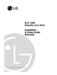
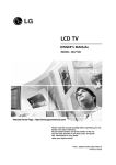
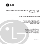
1
FMA-100 Configuration for FTG Operation
Entertainment-Lodging Industry Applications
Installation
& Configuration Guide
206-4071
©
Copyright 2009, LG Electronics U.S.A., Inc.
For Customer Support/Service, please call:
1-888-865-3026
www.lgcommercial.com • www.zenith.com
RECORD Model and SERIAL NUMBER
The model and serial number of this appliance is located on
the back of the cabinet. For future reference, we suggest
that you record those numbers here:
Model No._________________Serial No. _______________
WARNING
RISK OF ELECTRIC SHOCK
DO NOT OPEN
WARNING: TO REDUCE THE RISK OF ELECTRIC SHOCK DO NOT REMOVE COVER (OR BACK). NO USER
SERVICEABLE PARTS INSIDE. REFER TO QUALIFIED SERVICE PERSONNEL
The lightning flash with arrowhead symbol, within an equilateral triangle, is intended to alert the user to the
presence of uninsulated “dangerous voltage” within the product’s enclosure that may be of sufficient magnitude
to constitute a risk of electric shock to persons.
The exclamation point within an equilateral triangle is intended to alert the user to the presence of important
operating and maintenance (servicing) instructions in the literature accompanying the appliance
WARNING:
TO PREVENT FIRE OR SHOCK HAZARDS, DO NOT EXPOSE THIS PRODUCT TO RAIN OR MOISTURE.
POWER CORD POLARIZATION:
This product is equipped with a 3-wire grounding-type alternating current line plug. This plug will fit into the power outlet
only one way. This is a safety feature. If you are unable to insert the plug fully into the outlet, contact your electrician to
replace your obsolete outlet. Do not defeat the safety purpose of the three-wire ground type plug.
NOTE TO CABLE/TV INSTALLER:
This reminder is provided to call the cable TV system installer’s attention to Article 820-40 of the National Electric Code
(U.S.A.). The code provides guidelines for proper grounding and, in particular, specifies that the cable ground shall be connected to the grounding system of the building, as close to the point of the cable entry as practical.
REGULATORY INFORMATION:
This equipment has been tested and found to comply with the limits for a Class B digital device, pursuant to Part 15 of the
FCC Rules. These limits are designed to provide reasonable protection against harmful interference when the equipment is
operated in a residential installation. This equipment generates, uses and can radiate radio frequency energy and, if not
installed and used in accordance with the instruction manual, may cause harmful interference to radio communications.
However, there is no guarantee that interference will not occur in a particular installation. If this equipment does cause
harmful interference to radio or television reception, which can be determined by turning the equipment off and on, the user
is encouraged to try to correct the interference by one or more of the following measures:
• Reorient or relocate the receiving antenna.
• Increase the separation between the equipment and receiver.
• Connect the equipment into an outlet on a circuit different from that to which the receiver is connected.
• Consult the dealer or an experienced radio/TV technician for help.
CAUTION:
Do not attempt to modify this product in any way without written authorization from LG Electronics U.S.A., Inc.
Unauthorized modification could void the user’s authority to operate this product.
COMPLIANCE:
The responsible party for this product’s compliance is: LG Electronics U.S.A., Inc.
1000 Sylvan Avenue, Englewood Cliffs, NJ 07632, USA • Phone: 1-201-816-2000.
Marketed and Distributed in the United States by LG Electronics U.S.A., Inc.
2000 Millbrook Drive, Lincolnshire, IL 60069
PAGE 2
© Copyright 2009, LG Electronics U.S.A., Inc.
206-4077
IMPORTANT SAFETY INSTRUCTIONS
SAFETY INSTRUCTIONS
Important safeguards for you and your new product
This product has been manufactured and tested with safety in mind. However, improper use can result in potential electrical shock
or fire hazards. To avoid defeating the safeguards that have been built into the new product, please read and observe the following
safety points when installing and using the new product, and save them for future reference.
Observing the simple precautions discussed in this installation and operating guide can help get many years of enjoyment and safe
operation that are built into the new product.
This product complies with all applicable U.S. Federal safety requirements.
1. Read Instructions
8. Transporting Product
All the safety and operating instructions should be read before
the product is operated.
2. Follow Instructions
A product and cart combination should be moved with care.
Quick stops, excessive force, and uneven surfaces may cause the
product and cart combination to overturn.
All operating and use instructions should be followed.
9. Attachments
3. Retain Instructions
Do not use attachments not recommended by the product manufacturer as they may cause hazards.
The safety and operating instructions should be retained for
future reference.
10. Ventilation
Unplug this product from the wall outlet before cleaning. Do
not use liquid cleaners or aerosol cleaners. Use a damp cloth
for cleaning.
Slots and openings in the cabinet are provided for ventilation
and to ensure reliable operation of the product and to protect
it from overheating, and these openings must not be blocked or
covered. The openings should never be blocked by placing the
product on a bed, sofa, rug, or other similar surface. This product should not be placed in a built-in installation such as a
bookcase or rack unless proper ventilation is provided or the
manufacturer’s instructions have been adhered to.
6. Water and Moisture
11. Power Sources
Do not use this product near water for example, near a bath
tub, wash bowl, kitchen sink, or laundry tub, in a wet basement, or near a swimming pool.
This product should be operated only from the type of power
source indicated on the marking label. If you are not sure of
the type of power supply to your home, consult your product
dealer or local power company. For products intended to operate from battery power, or other sources, refer to the operating
instructions.
4. Heed Warnings
All warnings on the product and in the operating instructions
should be adhered to.
5. Cleaning
7. Accessories, Carts, and Stands
Do not place this product on a slippery or tilted surface, or on
an unstable cart, stand, tripod, bracket, or table. The product
may slide or fall, causing serious injury to a child or adult, and
serious damage to the product. Use only with a cart, stand, tripod, bracket, or table recommended by the manufacturer, or
sold with the product. Any mounting of the product should follow the manufacturer’s instructions, and should use a mounting
accessory recommended by the manufacturer.
12. Power Cord Polarization (Some models)
This product is equipped with a three-wire grounding type
alternating-current power plug. This plug will fit into the power
outlet only one way. This is a safety feature. If you are unable
to insert the plug fully into the outlet, contact your electrician
to replace your obsolete outlet. Do not defeat the safety purpose of the three-wire ground-type plug.
13. Power Cord Protection
Power-supply cords should be routed so that they are not likely
to be walked on or pinched by items placed upon or against
them, paying particular attention to cords at plugs, convenience receptacles, and the point where they exit from the product.
PORTABLE CART WARNING
206-4077
PAGE 3
IMPORTANT SAFETY INSTRUCTIONS
(Continued from previous page)
14. Outdoor Antenna Grounding
If an outside antenna or cable system is connected to the
product, be sure the antenna or cable system is grounded so as
to provide some protection against voltage surges and built-up
static charges. Article 810 of the National Electrical Code
(U.S.A.), ANSI/ NFPA 70 provides information with regard to
proper grounding of the mast and supporting structure,
grounding of the lead-in wire to an antenna discharge unit,
size of grounding conductors, location of antenna-discharge
unit, connection to grounding electrodes, and requirements for
the grounding electrode.
Example of Grounding According to National Electrical
Code Instructions
Ground Clamp
Antenna Lead in Wire
Antenna Discharge Unit
(NEC Section 810-20)
Electric Service
Equipment
Grounding Conductor
(NEC Section 810-21)
Ground Clamps
Power Service Grounding
Electrode System (NEC
Art 250, Part H)
NEC - National Electrical Code
15. Lightning
For added protection for this product (receiver) during a lightning storm, or when it is left unattended and unused for long
periods of time, unplug it from the wall outlet and disconnect
the antenna or cable system. This will prevent damage to the
product due to lightning and power-line surges.
16. Power Lines
An outside antenna system should not be located in the vicinity of overhead power lines or other electric light or power circuits, or where it can fall into such power lines or circuits.
When installing an outside antenna system, extreme care
should be taken to keep from touching such power lines or circuits as contact with them might be fatal.
17. Overloading
Do not overload wall outlets and extension cords as this can
result in a risk of fire or electric shock.
18. Object and Liquid Entry
Never push objects of any kind into this product through
openings as they may touch dangerous voltage points or
PAGE 4
short-out parts that could result in a fire or electric shock.
Never spill liquid of any kind on the product.
19. Servicing
Do not attempt to service this product yourself as opening or
removing covers may expose you to dangerous voltage or other
hazards. Refer all servicing to qualified service
personnel.
20. Damage Requiring Service
Unplug this product from the wall outlet and refer servicing to
qualified service personnel under the following
conditions:
a. If the power-supply cord or plug is damaged.
b. If liquid has been spilled, or objects have fallen into the
product.
c. If the product has been exposed to rain or water.
d. If the product does not operate normally by following the
operating instructions. Adjust only those controls that are
covered by the operating instructions as an improper
adjustment of other controls may result in damage and will
often require extensive work by a qualified technician to
restore the product to its normal operation.
e. If the product has been dropped or the cabinet has been
damaged.
f. If the product exhibits a distinct change in performance.
21. Replacement Parts
When replacement parts are required, be sure the service technician has used replacement parts specified by the manufacturer or have the same characteristics as the original part.
Unauthorized substitutions may result in fire, electric shock, or
other hazards.
22. Safety Check
Upon completion of any service or repairs to this product, ask
the service technician to perform safety checks to determine
that the product is in proper operating condition.
23. Wall or Ceiling Mounting
The product should be mounted to a wall or ceiling only as recommended by the manufacturer. The product may slide or fall,
causing serious injury to a child or adult, and serious damage
to the product.
24. Heat
The product should be situated away from heat sources such as
radiators, heat registers, stoves, or other products (including
amplifiers) that produce heat.
206-4077
Table of Contents / Setup Checklist
Warnings . . . . . . . . . . . . . . . . . . . . . . . . . . . . . . . . . .
Important Safety Instructions . . . . . . . . . . . . . . . . . . 3 Table of Contents . . . . . . . . . . . . . . . . . . . . . . . . . . . .
Setup Checklist . . . . . . . . . . . . . . . . . . . . . . . . . . . . . .
FTG Management Appliance Overview . . . . . . . . . . . . . . . .
FMA-100 Installation Procedures . . . . . . . . . . . . . . . . . . .
2
4
5
5
6
7
Configure the Laptop / Tablet . . . . . . . . . . . . . . . . . . . . 8
Configure the Channel Lineup . . . . . . . . . . . . . . . . . . . . 9
Connect FMA-100 to the Hotel’s Distribution Resources /
Troubleshooting . . . . . . . . . . . . . . . . . . . . . . . . . . . . . 10
Glossary of Terms . . . . . . . . . . . . . . . . . . . . . . . . . . . . 11
Warranty . . . . . . . . . . . . . . . . . . . . . . . . . . . . Back Cover
Setup Checklist
Installation and configuration of the FMA-100 requires the following hardware, tools and software.
•
•
•
•
•
•
•
•
•
•
•
•
FMA-100
Manual
Warranty sheet
75-ohm coaxial terminator (for the FMA-100 RF In port)
7 foot Ethernet crossover cable (for laptop or tablet access)
Low pass filter (6MLP-50)
Laptop or tablet with Ethernet port*
Ethernet straight-through cable (for hotel network access)*
Coaxial cable barrel adapter*
Coaxial jumper cables* (Use jumper cable(s) to protect filter from damage)
RF coaxial cable barrel*
Termcode**
- Version 2.58 or higher for HC11 terminals
- Version 6.0 or higher for HC12 terminals
*
These items are not included in the FMA-100 shipping container but are necessary to configure and install the
FMA-100.
** Terminals installed at sites using the FMA-100 must have the appropriate version of termcode loaded depending on
the terminal type.
206-4077
PAGE 5
FTG Management Appliance Overview
Purpose and Definition
FMA-100 Output
The FTG Management Appliance (FMA-100) is used to configure
and deliver the channel lineup to the guest room terminals via
the hotel’s coaxial distribution. Channel lineup changes are
completed without requiring room visits.
• The FMA-100 outputs a 42dB signal at a frequency of 50.5
MHz.
• The FMA-100 output should have a low pass filter (6MLP-50)
installed to protect channels 2 and 3 from any potential RF
interference produced by the FMA-100.
• The FMA-100 output should be padded as necessary to meet
the 3-10 dB signal level in the guest room.
This manual provides the steps to install, configure and troubleshoot the FMA-100.
FMA-100 Automatic Updates
Tips and Warnings
FMA-100 Configuration
• The FMA-100 configuration can only be performed on site.
Remote connectivity for configuration or troubleshooting is
not available.
• For ease of configuration, the FMA-100 should be installed in
the FTG rack prior to configuration.
• If the configuring laptop is running Windows Vista, resetting
the power on the FMA-100 while the laptop is connected may
cause a network conflict issue. To correct a network conflict,
disable and then enable the network interface on the laptop
and refresh the browser page.
• The FMA-100 default IP address is 10.20.1.128. To configure
the FMA-100, the configuring laptop or tablet must be on the
same subnet (255.255.248.0) as the FMA-100.
• Up to 100 channels can be configured with the FMA-100, but
only 20 channels can be viewed or configured at a time.
• After configuring a page or range of channels, the configuration must be saved before proceeding to the next page or
range of channels. If the configuration is not saved, the
channel configurations for that page will be lost.
PAGE 6
• Upon power-up, the FMA-100 will search for a DHCP server to
obtain an IP address and receive automatic date/time
updates. If a DHCP server is not found within 60 seconds,
the FMA-100 will revert to the default IP address
(10.20.1.128).
• The date and time will require reconfiguration each time
power is lost on the FMA-100 unless it is connected to a
hotel network with a DHCP server and Internet access.
FMA-100 Channel Lineup
• The FMA-100 will broadcast the channel lineup and the
time/date every 5 minutes. This allows a terminal to be
replaced in a room without additional configuration.
LG TVs with LG Jack Packs
• If the LG TV’s Auxiliary (Aux) channel is configured as the
Startup Channel in the FMA-100’s channel lineup, the TV will
power on to a split screen. Always configure the Startup
Channel to a channel other than the Aux channel.
206-4077
FMA-100 Installation Procedures
Purpose and Definition
Delivery of the channel lineup requires the installation and configuration of an FTG Management Appliance (FMA-100). This
section contains steps to install and configure the FMA-100.
Install the FMA-100 in an FTG Rack
FMA-100 Connections
1. Mount the FMA-100 in the FTG rack,
if applicable.
2. Plug the FMA-100 into the FTG rack’s power strip,
if applicable.
Refer to the FMA-100 diagram and connectivity table for connections and port information.
Complete the following steps to install the FMA-100 in
the FTG rack.
FMA-100 Connectivity
Port Name
Ethernet
RF Out
RF In
Serial Out
Kports 0-9
Description
Connects via Ethernet (crossover) cable to the
laptop or tablet for configuration purposes.
Connects via Ethernet (straight-through) cable
to the hotel’s network, if available.
Connects via coaxial cable to the combiner in
the FTG rack.
Not Applicable
Not Applicable
Not Applicable
ETHERNET
SERIAL OUT
RF IN
To Hotel
Network
RF OUT
75 ohm
Terminator
To Guest
Rooms
6MLP-50
Filter
To AC
Power
FMA & FTG
Combiner
Free-To-Guest
206-4077
PAGE 7
Configure the Laptop / Tablet
Configure the Laptop/Tablet
Complete the following steps to configure the laptop or tablet
that will be used to configure the FMA-100.
Windows XP
1.
2.
3.
4.
5.
6.
7.
Right-click on My Network Places on the desktop.
Select Properties.
Right-click on the Local Area Connection icon.
Select Properties.
Select Internet Protocol (TCP/IP).
Select the Use the following IP address radio button.
Type an IP address from the following range:
10.20.1.81 – 10.20.1.92
8. Type 255.255.248.0 in the Subnet mask field.
9. Select OK twice.
Windows Vista
1.
2.
3.
4.
5.
6.
7.
8.
Select the Start button on the desktop.
Right-click on Network.
Select Properties.
Select Manage Network Connections.
Right-click on Local Area Connection.
Select Properties.
Select the Use the following IP address radio button.
Type an IP address from the following range:
10.20.1.81 – 10.20.1.92
9. Type 255.255.248.0 in the Subnet mask field.
10. Select OK twice.
Connect to the FMA-100
Complete the following steps to access the FMA-100 software.
1. Connect an Ethernet (crossover) cable between the Ethernet
port on the laptop/tablet and the FMA-100’s Ethernet port.
PAGE 8
2. Launch a web browser.
3. Type http://10.20.1.128 in the browser’s address bar and
press <Enter>. The Current Channel Lineup screen will display.
Configure the Date and Time
Set Date and Time on the FMA-100
1. Select the Configure Date/Time link at the bottom of the
Current Channel Lineup screen to display the System
Date/Time Configuration screen.
2. Modify the following System Date/Time Configuration fields.
• Month
• Day of Month (1-31)
• Year (2008-2047)
• Day of Week
• Hour (0-23)
• Minutes (0-59)
• Seconds (0-59)
3. If the FMA-100 will be connected to the hotel’s network,
configure the following fields under *Internet Time Server
Settings.
Note: The hotel’s network must have a DHCP server and Internet
access for the FMA-100 to receive automatic time/date updates.
• Time Zone
• Observe DST (Daylight Savings Time)
4. Select the Save Time/Date button.
Note: After selecting the Save Time/Date button, the screen
will begin to refresh/reload. Wait for the screen to completely
reload before proceeding to the next step.
5. Select the View Channel Lineup link to return to the Current
Channel Lineup screen.
206-4077
Configure the Channel Lineup
1. Select the Configure Channel Lineup link. A login screen will
appear.
2. Type lnet in the User name field.
3. Type the appropriate password in the Password field.
4. Select the OK button.
5. Use the Channel Select drop-down list to select the channel
range to configure.
Note: Up to 100 channels can be configured in the FMA-100,
but only 20 channels can be viewed or configured at a time.
6. Select the Go button to display the selected channel range.
7. Add the FTG channels to the lineup.
• Select the appropriate tuning type from the Tuning Type
drop-down list.
• Type the analog modulator in the Analog Mod field,
if applicable.
• Type the digital modulator in the Digital Mod field,
if applicable.
• Type the digital stream in the Digital Stream field,
if applicable.
• Type the FTG channel’s OSD (On Screen Display) in the
OSD field.
- The OSD and Call Letters fields (combined) can have a
max of 17 characters including spaces.
- If a channel has both OSD and Call Letters they will be
separated by a dash (-) on the TV’s OSD. Note: The dash
will count as one of the 17 characters that can be used.
206-4077
• Type the station’s call letters in the Call Letters field.
• Select Enabled from the State drop-down box.
• Repeat these steps for each additional FTG channel listed
on the page.
8. Select the Save Configuration button after all the FTG
channels on the page have been configured.
Warning: The Save Configuration button must be selected before
configuring or editing the channel lineup for a different
channel range! If the Save Configuration button is not
selected before configuring a different page of channels, the channel configurations for that page will be lost!
9. Repeat the channel configuration steps for another channel
range until all FTG channels are configured.
10. Type the first channel the TV should access when it is powered on in the Startup Channel field.
Notes:
• If the Startup Channel is disabled, the lowest enabled
channel will default as the new Startup Channel.
• Auxiliary sources should not be configured as the Startup
Channel.
11. Select the Save Configuration button.
12. Wait for the page to refresh/reload.
13. Select the View Channel Lineup link to return to the Current
Channel Lineup screen.
PAGE 9
Connect the FMA-100 to the Hotel’s Distribution Resources/Troubleshooting
Complete the following steps to connect the FMA-100 to the
hotel’s coaxial distribution and Internet connection.
Note: If the signal level is not between 3 and 10 dB,
communications will be negatively affected, resulting in a
partial or missing channel lineup.
1. Connect the FMA-100 to the hotel’s coaxial distribution and
Internet connection.
2. Verify the forward signal (50.5 MHz) is between 3 dB and 10
dB in the guest rooms.
3. Verify that all viewable channels have a signal level
between 3 dB and 10 dB in the guest rooms.
FMA-100 Troubleshooting
Reset The Channel Lineup
The following contains general issues and solutions related to
the FMA-100.
The reset channel lineup function enables technicians to reset
or clear all configured channels from the FMA-100 channel lineup. This function may be used - but is not required - when a
significant number of channels require reconfiguration.
The OSD/Call letters do not display in the guest room(s).
• If the issue affects all rooms:
- Verify the FMA-100 is properly configured.
- Verify the FMA-100 is balanced flat.
• If the issue is restricted to a single room:
- Wait five minutes for the FMA-100 to re-broadcast the
channel lineup and re-test.
- Check the coaxial connections and signal levels in the
room.
- Replace the terminal.
The date/time is incorrect.
• If the FMA-100 is using the hotel’s network for the time
updates, verify the hotel’s network is operational.
• Reconfigure the Time Server in the FMA-100 software interface.
• If the FMA-100 is not connected to the hotel’s network or
does not use the hotel’s interface to receive time updates,
reconfigure the FMA-100’s date and time.
The laptop/tablet cannot access the FMA-100 interface.
• Verify the laptop/tablet settings are properly configured.
• Verify the Ethernet crossover cable is in good condition and
connected properly.
• Ping the FMA-100 IP address (10.20.1.128). If the FMA-100
does not respond, the FMA-100 will need to be replaced.
PAGE 10
Complete the following steps to reset the channel lineup.
1. Connect an Ethernet (crossover) cable between the
laptop/tablet’s Ethernet port and the FMA-100’s Ethernet
port. Tip: The laptop/tablet’s network settings must be on
the same subnet as the FMA-100.
2. Launch the laptop/tablet web browser.
3. Type http://10.20.1.128 in the browser’s address bar and
press <Enter>. The Current Channel Lineup screen will display.
4. Select the Configure Channel Lineup link. A login screen will
appear.
5. Type ‘lnet’ in the User name field. (LNET)
6. Type the ‘appropriate password’ in the Password field.
7. Select the OK button.
8. Select the Reset Channel Lineup link at the bottom of the
screen.
9. Select the Reset Configuration check box.
10. Select the Save Configuration button.
11. Wait for the check mark in the Reset Configuration check
box to disappear, indicating that all channels have been
removed from the channel lineup.
12. Reconfigure the channel lineup.
206-4077
Glossary of Terms
A list of definitions for some of the words found in this guide
75 OHM RF CABLE
The wire that comes from an off-air antenna
or cable service provider. The end looks like a
hex-shaped nut with a wire sticking through
the middle. It screws onto the threaded
Antenna/Cable jack on the back of the TV.
300 TO 75 OHM ADAPTER
A small device that connects a twowire 300 ohm antenna to a 75 ohm RF jack.
They are usually about an inch long with two
screws on one end and a round opening with
a wire sticking out on the other end.
ANALOG TELEVISION
Standard television broadcasting format in
4:3 picture aspect ratio.
DIGITAL TELEVISION
High-resolution, cinema-quality television
signals transmitted digitally.
DVI
Digital Video Interface
Accommodates analog and digital interfaces
with a single connector.
COMPOSITE VIDEO
Typical video jack, uses one wire for transporting three-color video signals.
COMPONENT VIDEO
Uses three wires for transporting three-color
video signals. The end result is usually better
video quality.
A/V CABLES
Audio/Video cables. Three cables bunched
together—right audio (red), left audio
(white), and video (yellow). A/V cables are
used for stereo playback of videocassettes
and for higher quality picture and sound
from other A/V devices.
DELETED
Lets you remove channels from the list that
the end user can scroll through using CH
(Channel) Up/Down.
A/V DEVICE
Any device that produces video or sound
(VCR, DVD, cable box, or television).
HDTV
High-definition television. Refers to television signals that have higher resolution than
ordinary analog TV signals.
AMPLIFIER
An electronic device that amplifies sound
from a television, CD player, VCR, DVD, or
other Audio/Video device.
ANTENNA
The physical receiver of television signals
sent over the air. A large metal piece of
equipment does not always have to be visible
to be using an antenna.
CABLE
Cable service box. Refers to the descrambler
box cable subscribers use to receive cable
programming signals.
CATV
Programming provided by a cable service.
206-4077
HDMI
High-definition multi-media interface.
HDSTB
High-definition set top box. Refers to a
tuner device that receives high-definition
television signals which have higher resolution than ordinary analog TV signals.
INPUT
Refers to the input jack that receives a signal from a TV, VCR, DVD Player or other
Audio/Video device.
JACK
An input or output connector on the back
of a TV, VCR, DVD Player or other
Audio/Video device.
MONO SOUND
Mono (monaural) sound is one channel of
sound. On more than one speaker, all the
speakers play the same audio.
OUTPUT
Refers to the output jack that sends a signal
out of a VCR, DVD, or other A/V device.
PHYSICAL CHANNEL NUMBER
See Note 1.
RGB (Red, Green, Blue)
Connection input or output port available for
producing a video image using three separate
colors: Red, Green, and Blue.
RS-232
Serial communication port through which the
TV software is updated.
2ND AUDIO PROGRAMMING/SAP
Second Audio Programming (SAP) is another,
separate audio channel available with some
programming. Choosing SAP often refers to
listening to audio in another language, such
as Spanish or French.
SIGNAL
Picture and sound traveling through a cable,
or over the air, to the TV.
STEREO SOUND
Stereo (Stereophonic) sound refers to audio
that’s divided into right and left sides.
TUNER
Device that picks up the broadcast signal
and turns it into picture and sound.
VIRTUAL CHANNEL NUMBER
See Note 1.
XDS
Extended Data Service: Additional program
information included on the signal provided
at the discretion of the broadcaster.
Note 1
Refer to www.atsc.org for further information.
PAGE 11
FMA-100 Warranty
Broadcast Products
Welcome to the LG family! We believe that you will be pleased with your new FMA-100. Please read this warranty carefully, it is a “LIMITED WARRANTY” as defined under Federal Law. This warranty gives you specific legal rights, and you may
also have other rights that vary from state-to-state within the U.S.A.
LG’s RESPONSIBILITY
Warranty Term
Parts
One year parts and labor from date of purchase or delivery date.
New or remanufactured replacements for factory-defective parts may be used. Such replacement parts are warranted for
the remaining portion of the original warranty period.
Warranty Service
Warranty service is provided at LG. Customer pays for shipping charges to LG, LG pays for return shipping charges to
return FMA-100 to customer. Call 1-888-865-3026 for further information.
Not Covered
This warranty covers manufacturing defects and does not cover installation, adjustment of customer controls, installation
or repair of antenna systems, cable converters or cable company-supplied equipment; it also does not cover damage due
to misuse, abuse, negligence, acts of God or other causes beyond the control of LG. Any alteration of the product after
manufacture voids this warranty in its entirety.
This warranty does not cover any missing or stolen cards.
THIS WARRANTY IS IN LIEU OF ANY OTHER WARRANTY, EXPRESS OR IMPLIED, INCLUDING WITHOUT LIMITATION,
ANY WARRANTY OF MERCHANTABILITY OR FITNESS FOR A PARTICULAR PURPOSE, AND LG SHALL NOT BE LIABLE FOR
ANY CONSEQUENTIAL, INDIRECT, OR INCIDENTAL DAMAGES OF ANY KIND, INCLUDING LOST REVENUES OR PROFITS
IN CONNECTION WITH THIS PRODUCT. SOME STATES DO NOT ALLOW LIMITATIONS ON HOW LONG AN IMPLIED WARRANTY LASTS OR THE EXCLUSION OR LIMITATION OF INCIDENTAL OR CONSEQUENTIAL DAMAGES, SO THE ABOVE LIMITATIONS OR EXCLUSIONS MAY NOT APPLY TO YOU.
OWNER’S RESPONSIBILITY
Effective Warranty Date
Warranty begins on the date of delivery of the FMA-100.
For your convenience, keep the dealer’s dated bill of sale or delivery ticket as evidence of the purchase date.
Installation Guide
Read the Installation and Setup Guide carefully so that you will understand the operation of the FMA-100 and how to
adjust the controls.
Antenna
Warranty Service
Reception problems caused by inadequate antenna or faulty antenna connections are the owner’s responsibility.
For warranty service information, Call 1-888-865-3026. Parts and service labor that are LG’s responsibility (see above)
will be provided without charge. Other service is at the owner’s expense. If you have any problem in obtaining satisfactory warranty service, call 1-888-865-3026.
You must provide the model number, serial number and date of purchase or date of original installation.
For Customer Support/Service please call:
1-888-865-3026
www.lgcommercial.com
206-4077
© Copyright 2009, LG Electronics U.S.A., Inc.
Issue*