1
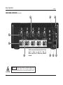
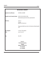
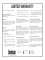
LX
Power Amplifier
User Guide
IMPORTANT SAFETY INSTRUCTIONS
1)
Read these instructions.
2)
Keep these instructions.
3)
Heed all warnings.
4)
Follow all instructions.
5)
Do not use this apparatus near water.
6)
Clean only with a dry cloth.
7)
In CE countries, this amplifier is considered “professional equipment.” In order to comply with CE requirements, the customer is required to obtain permission from the local supply authority
before connecting this equipment.
8)
Do not block any ventilation openings. Install in accordance with the manufacturer’s instructions.
9)
Do not install near any heat sources such as radiators, heat registers, stoves, or other apparatuses that produce heat.
10) Do not defeat the safety purpose of the polarized or grounding-type plug. A polarized plug has two blades with one wider than the other. A grounding-type plug has two blades and a third
grounding prong. The wide blade or the third prong is provided for your safety. If the provided plug does not fit into your outlet, consult an electrician for replacement of the obsolete outlet.
11) Protect the power cord from being walked on or pinched, particularly at plugs, convenience receptacles, and the point where they exit from the apparatus.
12) Only use attachments/accessories specified by the manufacturer.
13)
Use only with a cart, stand, bracket, or table specified by the manufacturer, or sold with the apparatus. When a cart is used, use caution when moving the cart/apparatus
combination to avoid injury from tip-over.
14) Unplug this apparatus during lightning storms or when unused for long periods of time.
15) Refer all servicing to qualified service personnel. Servicing is required when the apparatus has been damaged in any way, such as power-supply cord or plug is damaged, liquid has been
spilled or objects have fallen into the apparatus, the apparatus has been exposed to rain or moisture, does not operate normally, or has been dropped.
16) To reduce the risk of fire or electric shock, do not expose this apparatus to rain or moisture.
This triangle, which appears on your component,
alerts you to the presence of uninsulated,
dangerous voltage inside the enclosure voltage that may be sufficient to
constitute a risk of shock.
CAUTION
RISK OF ELECTRIC SHOCK
DO NOT OPEN
This triangle, which appears on your component,
alerts you to important operating and
maintenance instructions in this
accompanying literature.
DOCUMENTATION CONVENTIONS
This document contains general safety, installation, and operating instructions for the LX-5 and LX-7 Power Amplifiers. It is important to
read this user guide before attempting to use these products. Pay particular attention to safety instructions.
The following symbols are used in this document:
Appears on the component to indicate the presence of uninsulated, dangerous voltage inside the enclosure –
voltage that may be sufficient to constitute a risk of shock.
Lexicon, Inc.
3 Oak Park
Bedford, MA 01730-1441 USA
Tel
781-280-0300
Fax 781-280-0490
www.lexicon.com
CAUTION
Calls attention to a procedure, practice, condition or the like that, if not correctly performed or adhered to, could result
in injury or death.
WARNING
Calls attention to a procedure, practice, condition or the like that, if not correctly performed or adhered to, could result
in damage to or destruction of part or all of the product.
Note:
Calls attention to information that is essential to highlight.
Manufactured under license from Lucasfilm, Ltd. “Lucasfilm” and “THX” are trademarks or registered trademarks of Lucasfilm, Ltd.
Customer Support
Tel
781-280-0300
Fax 781-280-0495 (Sales)
Fax 781-280-0499 (Service)
© 2003 Lexicon, Inc. All rights reserved.
Lexicon Part No. 070-14876 | Rev 3 | 03/03
This document should not be construed as a commitment on the part of Lexicon, Inc. The information it contains is subject to change without notice. Lexicon, Inc. assumes
no responsibility for errors that may appear within this document.
Introduction
Introduction
Lexicon
Section 1: Getting Started
About the LX Power Amplifiers . . . . . . . . . . . . . . . . . . . . . . . 1-2
Unpacking and Inspection . . . . . . . . . . . . . . . . . . . . . .iii
Auspackend und Inspektion . . . . . . . . . . . . . . . . . . . . .iii
Desempaquetando e Inspección . . . . . . . . . . . . . . . . . .iii
Déballer et Inspectión . . . . . . . . . . . . . . . . . . . . . . . . .iii
Highlights
Product Registration . . . . . . . . . . . . . . . . . . . . . . . . . . . . . . . 1-3
Installation Considerations. . . . . . . . . . . . . . . . . . . . . . . . . . . 1-3
Spacchettando ed Ispezione . . . . . . . . . . . . . . . . . . . . .iii
Section 2: Basic Operation
Desempacotando e Inspeção . . . . . . . . . . . . . . . . . . . .iii
Front Panel Overview . . . . . . . . . . . . . . . . . . . . . . . . . . . . . . 2-2
Rear Panel Overview . . . . . . . . . . . . . . . . . . . . . . . . . . . . . . . 2-4
Cooling System . . . . . . . . . . . . . . . . . . . . . . . . . . . . . . . . . . 2-8
Protection Modes . . . . . . . . . . . . . . . . . . . . . . . . . . . . . . . . . 2-8
Thermal Protection • DC Protection
Section 3: Troubleshooting and Maintenance
Troubleshooting . . . . . . . . . . . . . . . . . . . . . . . . . . . . . . . . . . 3-2
Maintenance . . . . . . . . . . . . . . . . . . . . . . . . . . . . . . . . . . . . 3-3
Appendix
Specifications . . . . . . . . . . . . . . . . . . . . . . . . . . . . . . . . . . . . A-2
Declaration of Conformity . . . . . . . . . . . . . . . . . . . . . . . . . . . A-4
Index
ii
Introduction
LX Power Amplifiers
UNPACKING AND INSPECTION
After unpacking the unit, save all packing materials in case the unit
ever needs to be shipped. Thoroughly inspect the modules and
packing materials for signs of damage. Report any damage
to the carrier at once; report equipment malfunction to the
dealer.
DÉBALLER ET INSPECTIÓN
Après avoir déballé l'unité, sauve toutes les matières de l'emballage
au cas où vous avez besoin jamais de transporter l'unité.
Entièrement inspectez les modules et emballer des matières pour
signes de dégât. Rapportez tout dégât au porteur à la fois;
fonctionnement défectueux du matériel du rapport à votre
revendeur.
AUSPACKEND UND INSPEKTION
Überprüfen Sie die Verpackung auf Beschädigung. Nehmen Sie das
Gerät aus der Verpackung. Heben Sie das gesamte
Verpackungsmaterial auf, falls das Gerät einmal verschickt werden
muss. Überprüfen Sie alle Bestandteile auf Beschädigung.
Verständigen Sie sofort den Spediteur, falls die Verpackung
und/oder die Bestandteile der Lieferung beschädigt sind.
Verständigen Sie sofort Ihren Händler, falls das Gerät nicht richtig
funktioniert.
DESEMPAQUETANDO E INSPECCIÓN
Después de desempaquetar la unidad, ahorra todos los materiales
del embalaje en caso de que usted alguna vez necesita enviar la
unidad. Completamente inspeccione los módulos y condensando
los materiales para las señales de daño. Informe cualquier daño en
seguida al portador; el funcionamiento defectuoso de equipo de
informe a su distribuidor.
SPACCHETTANDO ED ISPEZIONE
Dopo avere spacchettato l'unità, mai salvi tutti i materiali di
imballaggio in caso che Lei ha bisogno di inviare l'unità.
Completamente ispezioni i moduli e comprimendo materiali per
segnali di danno. Subito riporti alcun danno al corriere;
malfunzionamento di attrezzatura di rapporto al Suo rivenditore.
DESEMPACOTANDO E INSPEÇÃO
Depois de desempacotar a unidade, economiza todos os materiais
de embalagem no caso de você já precisa transportar a unidade.
Completamente inspecione os módulos e empacotando materiais
para sinais de dano. Informe qualquer dano imediatamente ao
portador; mau funcionamento de equipamento de relatório para
seu negociante.
iii
1
Getting Started
About the LX Power Amplifiers . . . . . . . . . . . . . . . . . . . . . . . . . . . . . . . . . . . . . . . . . . . . . . . 1-2
Highlights
Product Registration . . . . . . . . . . . . . . . . . . . . . . . . . . . . . . . . . . . . . . . . . . . . . . . . . . . . . . 1-3
Installation Considerations . . . . . . . . . . . . . . . . . . . . . . . . . . . . . . . . . . . . . . . . . . . . . . . . . . 1-3
Getting Started
ABOUT THE LX POWER AMPLIFIERS
Thank you for purchasing an LX Power Amplifier, a reference-quality amplifier designed to meet the highest standards of power and
performance under even the most extreme operating conditions.
Equipped with advanced thermal, DC, and speaker protection, the
LX amplifiers deliver reliable and exceptional performance with
most loudspeakers, including mismatched, reactive, and unusual
loads. In addition, the LX amplifiers include protection against
short circuits, component failures, miswiring, and internal faults.
Available in five or seven channel versions, the LX amplifiers
deliver high-power performance. Each 200-Watt channel includes
four custom-designed, hand-graded output transistors as well as a
160-volt power supply for extra headroom. Bridgeable architecture
allows the first four 200-Watt channels to be configured with up to
two 400-Watt channels for even higher-power output. Nonbridged channels are compatible with speaker impedances of 2Ω
and above, and bridged channels are compatible with speaker
impedances of 4Ω and above.
Complemented by the heavy-duty, gold-plated speaker output
connectors, the rear panel includes selectable balanced or unbalanced audio input on RCA and XLR or 1/4-inch Tip/Ring/Sleeve
connectors. A trigger input connector allows the LX amplifiers to
be controlled with associated components such as the MC-12 or
MC-8 Digital Controller. In addition, a ground lift switch can be
used to eliminate audible hum caused from multiple grounding
paths.
The LX amplifiers feature a Junction Temperature Simulation (JTS)
computer that predicts the internal temperature of each output
transistor to prevent overheating. Unlike similar technologies, JTS
combines the output voltage and current of each output transistor
1-2
Lexicon
with heatsink temperatures to arrive at an accurate internal temperature prediction. As a result, JTS prevents overheating even
when heatsink temperatures are relatively cool, allowing the LX
amplifiers to achieve maximum performance and reliability from
the output transistors.
In addition to JTS, the LX amplifiers include advanced thermal and
DC protection for each channel. Thermal protection automatically
deactivates channels exceeding 115°C, while DC protection prevents DC and frequencies below 10Hz from reaching the speakers.
Dedicated, multi-colored channel status LEDs are located on the
front panel to provide at-a-glance viewing of channel status at all
times.
With THX Ultra Certification, the LX amplifiers are certified to meet
the highest THX standards. Advanced thermal, DC, and speaker
protection further guarantee an exceptional performance under
even the most extreme operating conditions. Add to this incredible
power and wide-ranging flexibility, and the LX amplifiers are at
home in the most sophisticated and demanding home theaters.
Getting Started
LX Power Amplifiers
HIGHLIGHTS
PRODUCT REGISTRATION
•
200W per channel
•
Four custom designed, hand-graded output transistors per
channel
•
Bridgeable architecture for higher-power output (400W at 8Ω)
Please register the LX Power Amplifier within 15 days of purchase.
To do so, register online at www.lexicon.com or complete and
return the product registration card attached to the back cover of
this user guide. The product registration card serves no warranty
purposes. Retain the sales receipt as proof of warranty coverage.
•
Oversized toroidal power transformer with extraordinarily low
DC resistance and thermal protection
•
High-power supply voltage (160V) for extra headroom at the
outputs
•
THX Ultra Certification
•
Junction Temperature Simulation (JTS) to provide maximum
performance from output transistors
•
Thermal protection against overheating
•
Speaker protection against DC and frequencies below 10Hz
•
Protection against short circuits, device failures, miswiring, and
internal faults
•
Stable with mismatched, reactive, or unusual loads
•
Quiet, microprocessor-controlled, forced-air cooling to
minimize chassis size
•
Compatible with 2Ω speaker impedances (Individual Mode)
•
Trigger input for power control from an external device
•
RCA, XLR, and 1/4-inch tip/ring/sleeve inputs
•
GROUND LIFT switch
•
Heavy-duty gold plated outputs
•
Multi-color channel status LEDs
•
Rack-mount option available
INSTALLATION CONSIDERATIONS
The LX Power Amplifiers require special care during installation to
ensure optimal performance. The amplifiers should be installed in
an equipment rack using an optional rack-mount kit available from
Lexicon dealers or www.lexicon.com. Leave at least 2 inches of
open space around the top, sides, and rear of the amplifier for
proper ventilation.
•
Be careful when moving the LX Power Amplifiers,
which are quite heavy.
•
Do not obstruct the ventilation holes in the chassis.
CAUTION
1-3
2
Basic Operation
Front Panel Overview. . . . . . . . . . . . . . . . . . . . . . . . . . . . . . . . . . . . . . . . . . . . . . . . . . . . . . 2-2
Rear Panel Overview . . . . . . . . . . . . . . . . . . . . . . . . . . . . . . . . . . . . . . . . . . . . . . . . . . . . . . 2-4
Cooling System . . . . . . . . . . . . . . . . . . . . . . . . . . . . . . . . . . . . . . . . . . . . . . . . . . . . . . . . . . 2-8
Protection Modes . . . . . . . . . . . . . . . . . . . . . . . . . . . . . . . . . . . . . . . . . . . . . . . . . . . . . . . . 2-8
Thermal Protection • DC Protection
Basic Operation
Lexicon
FRONT PANEL OVERVIEW
1
1. Standby Button
Activates and deactivates standby mode when the LX amplifier
is powered on with the rear panel power switch. The standby
button performs no function when the LX amplifier is powered
off with the rear panel power switch.
When the unit is on, pressing the standby button activates
standby mode and deactivates the LX amplifier. When the unit
is in standby, pressing the standby button deactivates standby
mode and activates the LX amplifier. The red standby button
LED will flash for approximately five seconds. Then, the blue
channel status LEDs will light. If the red standby button LED
2-2
2
flashes rapidly and the blue channel status LEDs do not light,
the incoming AC voltage is too low or the temperature of the
transformer is too high. Refer to Section 3 for troubleshooting
information.
Note:
• Power is still supplied to the LX amplifier when
standby mode is activated.
Basic Operation
LX Power Amplifiers
1
2
2. Channel Status LEDs
Provide at-a-glance view of the status of each channel as
indicated in the table below:
Color
Constant Blue
Constant Bright Blue
Flashing Red
Color
Constant Red
Status
Status
(Continued)
A fault in the channel. Refer to
Section 3 for troubleshooting
information.
Normal Operation
≤1% distortion in the audio signal. Reduce volume level to help eliminate potentially
damaging audio signals from reaching the
speakers.
The temperature of the individual amplifier
card is too high. If this occurs, the channel will
not pass audio. The channel status LED will
light blue when the temperature of the amplifier card returns to normal. Then the channel
will automatically resume passing audio.
Note:
When the main power transformer temperature
exceeds 110˚C:
• the transformer will deactivate
•the channel status LEDs will no longer be lit
•the standby LED will flash rapidly
2-3
Basic Operation
Lexicon
REAR PANEL OVERVIEW
6
9
8
3
4
5
The LX-7 rear panel is shown above. The LX-5 rear
panel is shown on page 2-6. The rear panels are
similar, except the LX-7 amplifier includes two
additional channels.
WARNING External wiring connected to connectors marked with the
triangle pictured at the left requires installation by an
instructed person or the use of ready-made leads or cords.
2-4
7
2
1
Basic Operation
LX Power Amplifiers
1. Power Switch
4. OUTPUT 1 to 7 (LX-7) or 1 to 5 (LX-5)
Disconnects power to the AC Input Connector. Set this switch
to off when making or breaking connections to the amplifier,
or when changing the setting of the MODE switch.
2. AC Input Connector
The AC input connector provides power to the unit with the
supplied power cord (3 conductor, 14AWG). Do not use an
extension cord. For optimal performance, use an isolated
power receptacle with adequate current (15 or 20 amps). Line
voltages ≥10% above the specified voltage may damage the
amplifier. Line voltages ≤10% below the specified voltage may
cause the amplifier to enter a protection mode, indicated by
the red standby LED flashing.
Provide audio output for the speakers. OUTPUT connectors can
accept bare speaker wires, banana plug connectors, or certain
spade connectors. When using bare speaker wires, loosen the
connector, insert the wire into the top of the receptacle, then
tighten the connector. The same procedure should be used for
spade connectors. Banana plugs should be inserted into the
outward-facing receptacle.
Use heavy gauge speaker cable to ensure low-impedance
connections between the amplifier and the speakers. Observe
correct speaker polarity.
WARNING Do not connect the OUTPUTs of one channel to the
OUTPUTs of other channels or to other amplifiers.
3. INPUT 1 to 7 (LX-7) or 1 to 5 (LX-5)
Provide audio input for the speakers connected to the
corresponding audio outputs. When using the unbalanced
(RCA) audio inputs, make sure the UNBAL/BAL switch
located to the left of each XLR connector is set to UNBAL.
When using the balanced (XLR or 1/4-inch tip/ring/sleeve)
audio inputs, make sure the UNBAL/BAL switch is set to BAL.
The illustrations below show the appropriate cable ends for
1/4-inch T/R/S and XLR connectors.
Tip
Ring
2 = Positive
3 = Negative
1 = Ground
If the rear panel MODE switch is set to INDIVIDUAL,
speakers must have impedance ratings of 2Ω or
higher. If set to (BRIDGED), speakers must have
impedance ratings of 4Ω or higher. Using speakers
with lower than recommended impedance
ratings might activate protection modes.
Sleeve
Tip = Positive
Ring = Negative
Sleeve = Ground
Male
Cable End
Note:
5. MODE Switch
Configures channels 1 and 2 or 3 and 4 for INDIVIDUAL or
(BRIDGED) operation. When set to INDIVIDUAL, all INPUTs and
OUTPUTs function as separate channels. When set to
(BRIDGED), the selected INPUTs and OUTPUTs are combined
to create a single high-power channel.
. . . continued on page 2-7
2-5
Basic Operation
Lexicon
REAR PANEL OVERVIEW (continued)
6
9
8
3
4
5
The LX-5 rear panel is shown above. The LX-7 rear
panel is shown on page 2-4. Both are
similar, except the LX-7 features two additional
channels.
WARNING External wiring connected to connectors marked with the
triangle pictured at the left requires installation by an
instructed person or the use of ready-made leads or cords.
2-6
7
2
1
Basic Operation
LX Power Amplifiers
5. MODE Switch (continued from page 2-5)
Make sure the amplifier is powered off when the MODE switch
setting is changed.
INPUTs and OUTPUTs used in (BRIDGED) mode are labelled in
parenthesis. Do not use other INPUTs and OUTPUTs that are
not labelled in parenthesis. Connect the positive speaker lead
to the positive (red) OUTPUT of the first channel, and
connect the negative speaker lead to the positive (red)
OUTPUT of the second channel.
6. UNBAL/BAL Switch
Selects between unbalanced (RCA) or balanced (XLR, tip/ring/
sleeve) audio input for each channel. Power the amplifier off or
reduce system volume before changing the setting of the
UNBAL/BAL switch. If the amplifier is connected to a digital
controller such as the MC-12 or MC-8, output levels should be
re-calibrated whenever the setting is changed.
7. GROUND LIFT Switch
8. TRIGGER INPUT
Enables the amplifier to be controlled by the MC-12/MC-8 or
other external devices with a 12V DC trigger output. Connect
the trigger output of the external device to the TRIGGER INPUT
of the amplifer, and set the TRIGGER switch on the amplifier to
ON or DELAY. The amplifier will automatically respond when
the external device is powered on and off.
9. TRIGGER INPUT Switch
When set to OFF, the amplifier only powers on and off in
response to the front panel standby button. When set to ON
or DELAY, only the external device connected to the TRIGGER
INPUT can be used to power the amplifier on and off. The front
panel standby button will not power the unit on and off.
(However, the standby LED still functions normally.) When set
to DELAY, the normal 5 second power on delay is extended to
approximately 7 seconds.
The TRIGGER INPUT Switch setting will not take effect until the
amplifier has been power cycled.
When set to ON, isolates the ground connection between the
audio inputs and the chassis. This can be useful for
eliminating audible hum or noise caused by multiple
grounding paths in the system. When set to OFF, the audio
inputs are grounded to the chassis. This switch should be set to
ON whenever there is ground noise present in the system.
WARNING Do not defeat or remove the ground prong on the AC
power cord. This will result in a safety hazard, and will not
reduce audible hum. The GROUND LIFT switch has no
effect on the safety ground of the amplifier.
2-7
Basic Operation
COOLING SYSTEM
The LX Power Amplifiers use temperature-controlled fans to
exhaust heat. Heatsink temperatures are measured hundreds of
times each second. Under most conditions, the fans are set to a
slow speed. When the temperature climbs above 85˚C, the fans are
set to a medium speed. When the temperature climbs above
100˚C, the fans are set to a high speed.
PROTECTION MODES
The LX amplifiers are equipped to protect against overheating and
miswiring, as well as electrical failures such as short circuits, device
failures, internal faults, and DC output to the speakers. A
combination of dedicated circuitry and microprocessor control
ensures that the amplifier will perform safely and reliably under
extreme conditions.
THERMAL PROTECTION
JTS (Junction Temperature Simulation) provides an advanced level
of thermal protection that allows the LX amplifiers to achieve
maximum performance with a minimum number of output
transistors. This design requires a smaller quantity of high-quality
output transistors, enhancing performance and reliability.
JTS predicts the internal temperatures of output transistors to
prevent them from overheating. To arrive at an accurate internal
temperature prediction, JTS measures the output voltage and
current each output transistor delivers and combines this information with heatsink temperatures. When an output transistor
reaches its maximum allowable temperature, it is instantly restricted until the temperature decreases.
2-8
Lexicon
JTS’s dynamic nature enables it to avoid the problems inherent in
competing products that rely only on heatsink temperatures.
Heatsink temperatures do not always correlate to the temperatures
inside the output transistors. JTS is calibrated by device parameters,
which allow it to predict overheating even if the heatsinks are
relatively cool.
When JTS activates, a distorted signal will be present in the
corresponding channel. Check the airflow around the amplifier and
take the following measures:
•
Provide additional cooling.
•
Make sure speakers have adequate impedance ratings
(see page 2-5).
•
Reduce system volume level.
In addition to the protection provided by JTS, the amplifier includes
thermal protection for each channel and the main power
transformer. If a heatsink temperature exceeds 115˚C, the channel
will deactivate and the corresponding channel status LED will flash
red. When the heatsink cools below 115˚C, the channel will
automatically reactivate and the corresponding channel status LED
will light blue.
If the main power transformer temperature exceeds 110˚C, the
transformer will deactivate, all channel status LEDs will no longer
be lit, and the standby LED will flash rapidly. The internal fans will
automatically be set to full speed to cool the transformer. Once the
transformer has cooled enough, it will automatically be reset and
the amplifier will operate normally. The channel status LEDs will
light blue, and the standby LED will no longer be lit.
LX Power Amplifiers
Basic Operation
DC PROTECTION
Each channel includes DC protection to prevent DC and
frequencies below 10Hz from reaching the speakers. If this
protection activates, the output relay will open and the
corresponding front panel channel status LED will no longer be lit.
After approximately 4-seconds, DC protection will be
automatically deactivated. The relay will close and the
corresponding channel status LED will light blue. If DC or
frequencies below 10Hz are still present, DC protection will be
automatically reactivated. The amplifier will continue to engage
this protection until the problem is no longer present.
2-9
3
Troubleshooting & Maintenance
Troubleshooting . . . . . . . . . . . . . . . . . . . . . . . . . . . . . . . . . . . . . . . . . . . . . . . . . . . . . . . . . 3-2
Maintenance . . . . . . . . . . . . . . . . . . . . . . . . . . . . . . . . . . . . . . . . . . . . . . . . . . . . . . . . . . . . 3-3
Troubleshooting & Maintenance
Lexicon
TROUBLESHOOTING
No front panel LEDs are lit.
1. Make sure the unit is plugged in and the rear panel power
switch is set to on.
The Standby LED is flashing rapidly.
1. Power the amplifier off. Allow the amplifier to cool before
powering it on again.
2. Check the incoming line voltage. It should not be more than
10% below the mains supply voltage indicated in the
Specifications (page A-2).
One or more channels is not passing audio, but the
corresponding channel status LED is lit blue.
1. Make sure the UNBAL/BAL switch is set to the connector being
used (UNBAL for RCA and BAL for 1/4 inch or XLR).
2. Reduce system volume level.
Audio sounds out-of-phase.
1. Power the amplifier off with the rear panel power switch. Make
sure the MODE switch is set to the current configuration.
2. Check to ensure proper speaker wiring.
A humming sound is present in the audio.
One or more channels is not passing audio, and the
corresponding channel status LED is flashing red.
1. Set the GROUND LIFT switch to ON.
1. Reduce system volume level.
One or more channels is outputting distorted sound.
2. Power the amplifier off. Allow the amplifier to cool before
powering it on again.
1. Reduce system volume level.
2. Check the airflow around the amplifier and take the following
measures:
A channel status LED is lit red.
•
Provide additional cooling.
1. Contact an authorized Lexicon dealer or Lexicon customer
service.
•
Make sure speakers have adequate impedance ratings (see
page 2-5).
The standby button does not appear to be functioning.
1. Make sure the rear panel power switch is set to on.
The TRIGGER INPUT is connected to an external device, but the
amplifer does not power on and off with the external device.
2. Make certain the rear panel TRIGGER INPUT switch is set to
OFF.
1. Make sure the TRIGGER INPUT switch is set to ON or DELAY.
3-2
LX Power Amplifiers
Troubleshooting & Maintenance
The amplifier and other electrical devices in the listening room
suddenly lose power.
1. Reset the circuit breakers for the affected device(s).
If all else fails . . .
1. Contact an authorized Lexicon dealer.
2. Contact Lexicon customer service.
Note:
Visit www.lexicon.com for answers to frequently
asked questions and additional troubleshooting
information.
MAINTENANCE
The following routine maintenance should be performed on a
periodic basis:
•
Clean the exterior surfaces of the unit with a soft, dry, lint-free
cloth. Do not use alcohol, benzene, acetone-based cleaners, or
strong commercial cleaners. Do not use a cloth made with
steel wool or metal polish. If the unit is exposed to a dusty
environment, a low-pressure blower may be used to remove
dust from its exterior.
3-3
A
Appendix
Specifications . . . . . . . . . . . . . . . . . . . . . . . . . . . . . . . . . . . . . . . . . . . . . . . . . . . . . . . . . . . . . . . . . . . . . . . . . . A-2
Declaration of Conformity. . . . . . . . . . . . . . . . . . . . . . . . . . . . . . . . . . . . . . . . . . . . . . . . . . . . . . . . . . . . . . . . . A-4
Appendix
Lexicon
SPECIFICATIONS
Audio Input Connectors
Performance (Continued)
LX-7
Signal-to-Noise Ratio
LX-5
• 7 RCA, 7 XLR (including 1/4-inch Tip/Ring/Sleeve)
• 111dB
22kHz bandwidth, balanced inputs
• 5 RCA, 5 XLR (including 1/4-inch Tip/Ring/Sleeve)
• 109dB
Audio Output Connectors
LX-7
• 7 pairs of heavy-duty binding posts
LX-5
• 5 pairs of heavy-duty binding posts
Performance
Amplifier performance specifications are identical in INDIVIDUAL and (BRIDGED)
Modes, with the
exception of Output Power and Minimum Speaker
Impedance. (BRIDGED) Mode includes channels 1 & 2 and 3 & 4 only.
Output Power
(Ref 200W at 8Ω)
IM Distortion
• Below 0.03% at 200W, 8Ω
Crosstalk
• -80dB at 1kHz, minimum
Damping Factor
• 250 at 20Hz, minimum
Input Sensitivity
• 2V in for 100W out at 8Ω,
balanced inputs
• 200W at 8Ω,
all channels driven
20Hz to 20kHz
• 400W at 8Ω, (Bridged)
Minimum
Speaker
Impedance
• 2Ω, INDIVIDUAL Mode
• 4Ω, (BRIDGED) Mode
Frequency
Response
• 20Hz to 20kHz ±0.1dB
• 10Hz to 100kHz +0.5/-3dB
THD
• Below 0.02% at 200W, 8Ω
all channels driven
20Hz to 20kHz
A-2
22kHz bandwidth, unbalanced inputs
• 1V in for 100W out at 8Ω,
unbalanced inputs
Input Impedance
• 20kΩ, balanced
•10kΩ, unbalanced
Gain
•23 dB, balanced
•29dB, unbalaced
Other
Trigger Input
• 12V DC +/- 10%
Power Requirements
• 120V 60Hz 20 (Domestic)
• 230V 50Hz 12.5A
(Export)
LX Power Amplifiers
Appendix
Other (Continued)
Weight
LX-7
LX-5
Rack Mounting
• 56lbs (25.4kg)
• 52lbs (23.6kg)
Optional brackets are available for
mounting either amplifier in standard 9-inch equipment rack
Specifications are subject to change
without notice
A-3
Appendix
Lexicon
DECLARATION OF CONFORMITY
Application of Council Directive(s):
89/336/EEC and 93/68/EEC
Standard(s) to which Conformity is Declared:
EN 55103-1:1995, EN 61000-3-3:1995,
EN 55022:1992 (Class B), EN 55103-2:1996, and EN 60065:1998
Manufacturer:
Lexicon, Inc.
3 Oak Park
Bedford, MA 01730-1441 USA
The equipment identified here conforms to the Directive(s) and Standard(s) specified
above.
Type of Equipment:
LX-5 and LX-7 Power Amplifiers
Model:
Lexicon LX-5 and LX-7
Date:
March 2003
Lexicon, Inc.
Vice President of Engineering
3 Oak Park
Bedford, MA 01730-1441 USA
Tel: 781-280-0300
Fax: 781-280-0490
A-4
I
Index
(BRIDGED) Mode . . . . . . . . . . . . . . . . . . . . . .2-5, 2-7
AC Input Connector . . . . . . . . . . . . . . . . . . . . . . .2-5
AC Power Cord . . . . . . . . . . . . . . . . . . . . . . . . . . .2-7
BAL/UNBAL Switch . . . . . . . . . . . . . . . . .2-5, 2-7, 3-2
Channel Status LEDs . . . . . . . . .2-2, 2-3, 2-8, 2-9, 3-2
Connectors . . . . . . . . . . . . . . . . . . .2-4, 2-5, 2-6, 3-2
Cooling System . . . . . . . . . . . . . . . . . . . . . . . . . .2-8
DC Protection . . . . . . . . . . . . . . . . . . . . . . . . . . . .2-9
Declaration of Conformity . . . . . . . . . . . . . . . . . . .A-3
Documentation Conventions . . . . . . . . . . . . . . . . . . .i
Front Panel . . . . . . . . . . . . . . . . . . . . . . . .2-2 to 2-3
LX-7 . . . . . . . . . . . . . . . . . . . . . . .2-2 (Illustration)
LX-5 . . . . . . . . . . . . . . . . . . . . . . .2-3 (Illustration)
GROUND LIFT Switch . . . . . . . . . . . . . . . . . .2-7, 3-2
INDIVIDUAL Mode . . . . . . . . . . . . . . . . . . . . . . . .2-5
INPUTs . . . . . . . . . . . . . . . . . . .2-4, 2-5, 2-6, 2-7, 3-2
Inspection Instructions . . . . . . . . . . . . . . . . . . . . . . .iii
Junction Temperature Simulation (JTS) . . . . . . . . . .2-8
LEDs, Channel Status . . . . . . . . . . . . . . . . . . .2-3, 3-2
Limited Warranty . . . . . . . . . . . . . . .Inside Back Cover
Installation Considerations . . . . . . . . . . . . . . . . . . .1-3
LX Power Amplifiers, About . . . . . . . . . . . . .1-2 to 1-3
Maintenance . . . . . . . . . . . . . . . . . . . . . . . . . . . .3-3
Male Cable End, XLR . . . . . . . . . . . . .2-5 (Illustration)
MODE Switch . . . . . . . . . . . . . . . . . . . . .2-5, 2-7, 3-2
OUTPUTs . . . . . . . . . . . . . .2-4, 2-5, 2-6, 2-7, 2-8, 2-9
Power Outage . . . . . . . . . . . . . . . . . . . . . . . . . . .3-3
Power Switch . . . . . . . . . . . . . . . . . . . . . . . . .2-5, 3-2
Product Registration . . . . . . . . . . . . . . . . . . . . . . .1-3
Protection Modes . . . . . . . . . . . . . . . . . . . .2-8 to 2-9
RCA Connectors . . . . . . . . . . . . . . . . . . .2-5, 2-7, 3-2
Rear Panel . . . . . . . . . . . . . . . . . . . . .2-4 to 2-7, 3-2
LX-7 . . . . . . . . . . . . . . . . . . . . . . .2-4 (Illustration)
LX-5 . . . . . . . . . . . . . . . . . . . . . . .2-6 (Illustration)
Registration, Product . . . . . . . . . . . . . . . . . . . . . . .1-3
Safety Instructions . . . . . . . . . .Inside Front Cover, i, iii,
1-3, 2-4, 2-6, 2-7
Specifications . . . . . . . . . . . . . . . . . . . . . . . . . . . .A-2
Standby Button . . . . . . . . .2-2, 2-3, 2-5, 2-7, 2-8, 3-2
Table of Contents . . . . . . . . . . . . . . . . . . . . . . . . . . .ii
Thermal Protection . . . . . . . . . . . . . . . . . . . . . . . .2-8
Tip/Ring/Sleeve Cable End . . . . . . . . .2-5 (Illustration)
Tip/Ring/Sleeve Connectors . . . . . . . . . . . . . .2-5, 2-7
TRIGGER INPUT . . . . . . . . . . . . . . . . . . . . . . .2-7, 3-2
TRIGGER INPUT Switch . . . . . . . . . . . . . . . . .2-7, 3-2
Troubleshooting . . . . . . . . . . . . . . . . . . . . .3-2 to 3-3
UNBAL/BAL Switch . . . . . . . . . . . . . . . . .2-5, 2-7, 3-2
Unpacking Instructions . . . . . . . . . . . . . . . . . . . . . .iii
Warranty . . . . . . . . . . . . . . . . . . . . .Inside Back Cover
XLR Connectors . . . . . . . . . . . . . . . . . . .2-5, 2-7, 3-2
XLR Male Cable End . . . . . . . . . . . . . .2-5 (Illustration)
LIMITED WARRANTY
Lexicon, Inc. offers the following warranty on this product:
What is the Duration of this Warranty?
This warranty will remain in effect for five (5) years from the
original date of purchase.
Who is Covered?
This warranty may be enforced by the original purchaser and
subsequent owners during the warranty period, provided the
original dated sales receipt or other proof of warranty
coverage is presented at time of service.
Damage occurring during any shipment of this product.
Claims for shipping damages must be made with the
carrier.
3.
Include a copy of the original dated sales receipt. (A
copy of the original dated sales receipt must be
presented whenever warranty service is required.)
3.
Damage to a unit that has been altered, or on which the
serial number has been defaced, modified, or removed.
4.
Do not include accessories such as power cords or user
guides unless instructed to do so.
What Expenses will Lexicon, Inc. Assume?
What are the Limitations of Implied Warranties?
Lexicon, Inc. will pay all labor and material expenses for
covered items. Payment of shipping charges is discussed in
the next section of the warranty.
Any implied warranties, including warranties of
merchantability and fitness for a particular purpose, are
limited in duration to the length of this warranty.
How is Service Obtained?
What Certain Damages are Excluded?
Lexicon’s liability for a defective product is limited to repair or
replacement of that product, at our option. Lexicon, Inc. shall
not be liable for damages based on inconvenience; loss of
use of the product; loss of time; interrupted operation;
commercial loss; or any other damages, whether incidental,
consequential, or otherwise.
A.
Accident, misuse, abuse, or neglect.
When this product needs service, write, telephone, or fax
Lexicon, Inc. to request information about where the unit
should be taken or sent. When making a written request,
please include your name, complete address, and daytime
telephone number; the product model and serial numbers;
and a description of the problem. Do not return the unit to
Lexicon, Inc. without prior authorization.
B.
Failure to follow instructions contained in the user
guide.
When Shipping a Product for Service . . .
What is Covered?
This warranty covers all defects in material and
workmanship on this product, except as specified below. The
following are not covered:
1.
2.
Damage resulting from
C.
Repair or attempted repair unauthorized by
Lexicon, Inc.
D.
Failure to perform recommended periodic
maintenance.
E.
Causes other than product defects, including lack of
skill, competence, or experience on the part of the
owner.
How do State Laws Relate to this Warranty?
1.
Pay any initial shipping charges, which are the
responsibility of the owner. If necessary repairs are
covered by this warranty, Lexicon, Inc. will pay return
shipping charges to any destination in the United States
using the carrier of our choice.
2.
Pack the unit securely. Package insurance is strongly
recommended.
Lexicon, Inc.
3 Oak Park
Bedford, MA 01730-1413
USA
Tel 781-280-0300
Fax 781-280-0490
www.lexicon.com
Some states do not allow limitations on the duration of implied
warranties and/or the exclusion or limitation of incidental or
consequential damages. As such, the above limitations may
not apply.
This warranty is not enforceable outside of North America.
This warranty provides specific legal rights. Additional rights
may be provided by some states.
Customer Support
Tel 781-280-0300
Fax 781-280-0495 (Sales)
Fax 781-280-0499 (Service)
Lexicon, Inc.
3 Oak Park
Bedford, MA 01730-1413 USA
Tel
781-280-0300
Fax 781-280-0490
www.lexicon.com
Customer Support
Tel
781-280-0300
Fax 781-280-0495 (Sales)
Fax 781-280-0499 (Service)
Lexicon Part No. 070-14876 | Rev 3 | 03/03