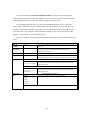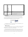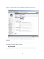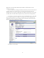
1
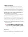
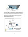
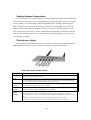
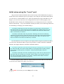
LevelOne WAB-1000
Outdoor Access Point/Bridge
User Guide
Copyright © 2004 All rights reserved. No part of this documentation may be reproduced in any form or by any
means or to make any derivative work (such as translation, transformation, or adaptation) without written permission
from the manufacturer.
The manufacturer reserves the right to revise this documentation and to make changes in content from time to
time without obligation on the part of the manufacturer to provide notification of such revision or change.
The manufacturer provides this documentation without warranty, term or condition of any kind, either implied or
expressed, including, but not limited to, the implied warranties, terms, or conditions of merchantability, satisfactory
quality, and fitness for a particular purpose. The manufacturer may make improvements or changes in the product(s)
and/or the program(s) described in this documentation at any time.
If there is any software or removable media described in this documentation, it is furnished under a license
agreement included with the product as a separate document, in the printed documentation, or on the removable media
in a readable file such as license.txt or the like. If you are unable to locate a copy of the license, contact the
manufacturer and a copy will be provided to you.
___________________________________
Windows is a registered trademark of Microsoft Corporation. Any other company and product name mentioned
herein is a trademark of the respective company with which they are associated.
Table of Contents
Chapter 1: Introduction............................................................................................................ 1
Basic Features...................................................................................................................... 1
Wireless Basics.................................................................................................................... 2
802.11b ............................................................................................................................ 3
802.11g ............................................................................................................................ 3
Network Configuration.................................................................................................... 3
Access point configurations............................................................................................. 3
Possible AP Topologies............................................................................................... 4
Bridging ........................................................................................................................... 5
Data Encryption and Security.......................................................................................... 5
SSID ................................................................................................................................ 6
WEP................................................................................................................................. 6
WPA with TKIP/ AES-CCMP ........................................................................................ 6
AES-ECB and 3DES for Bridging .................................................................................. 6
MAC Address Authentication ......................................................................................... 7
DHCP Server ................................................................................................................... 7
Operator Authentication and Management...................................................................... 7
Management .................................................................................................................... 8
Chapter 2: Hardware installation ............................................................................................. 9
Preparation for use............................................................................................................... 9
Installation Instructions ..................................................................................................... 10
Minimum system and component requirements................................................................ 10
Ensure the cabling is correctly installed ............................................................................ 10
Sealing Antenna Connections........................................................................................ 12
The Indicator Lights ...................................................................................................... 12
Chapter 3: Configure the WAB-1000 for use as an access point .......................................... 13
Introduction ....................................................................................................................... 13
Preliminary configuration steps......................................................................................... 13
Initial setup using the “Local” port.................................................................................... 14
System Configuration ........................................................................................................ 15
General .......................................................................................................................... 15
WAN.................................................................................................................................. 16
LAN............................................................................................................................... 17
Wireless Setup ................................................................................................................... 18
General .......................................................................................................................... 18
Encryption ..................................................................................................................... 21
WEP Encryption ........................................................................................................ 21
WPA Encryption........................................................................................................ 22
MAC Address Filtering ................................................................................................. 24
Bridging and Bridging Encryption ................................................................................ 25
Rogue AP Detection ...................................................................................................... 26
Advanced ....................................................................................................................... 27
Services Settings................................................................................................................ 28
DHCP Server ................................................................................................................. 28
SNMP Agent.................................................................................................................. 29
User Management.............................................................................................................. 30
List All Users................................................................................................................. 30
Add New User ............................................................................................................... 31
Monitoring/Reports ........................................................................................................... 31
System Status................................................................................................................. 32
Bridging Status .............................................................................................................. 32
Wireless Clients............................................................................................................. 33
Adjacent AP List ........................................................................................................... 34
DHCP Client List........................................................................................................... 34
System Log .................................................................................................................... 35
Web Access Log............................................................................................................ 35
Network Activity ........................................................................................................... 36
System Administration ...................................................................................................... 37
Firmware Upgrade......................................................................................................... 37
Factory Default .............................................................................................................. 37
Remote Logging ............................................................................................................ 38
Reboot............................................................................................................................ 38
Utilities .......................................................................................................................... 39
Chapter 4: Configure the WAB-1000 as a bridge ................................................................. 40
Introduction ....................................................................................................................... 40
General bridge setup .......................................................................................................... 40
Set up bridging type........................................................................................................... 43
Point-to-point bridge configuration ........................................................................... 43
Point-to-multipoint bridge configuration....................................................................... 47
Repeater bridge configuration ....................................................................................... 49
Chapter 5: Technical Support ................................................................................................ 51
Manufacturer’s Statement.................................................................................................. 51
Radio Frequency Interference Requirements .................................................................... 51
Channel Separation and WLAN Cards.............................................................................. 51
Glossary ................................................................................................................................. 52
Chapter 1: Introduction
This manual covers the installation and operation of Level One’s WAB-1000 Outdoor
Access Point. The WAB-1000 is a ruggedized access point/ bridge, which is intended for use in
industrial and external environments. It accommodates both 802.11b WLAN and 802.11g
WLAN access and uses Power over Ethernet (PoE) access to the Ethernet WAN to eliminate the
need for internal access point power supply units (AC-DC converters) and 110-220V cabling
installations. The wireless LANs can include mobile devices such as handheld Personal Data
Assistants (PDAs), mobile web pads, and wireless laptops. The WAB-1000 employs state-of-theart AES or 3DES encryption for bridging. If encryption is desired in the access point mode,
either static WEP or WPA (using TKIP or AES-CCMP) can be employed. This allows you to
employ legacy client WEP cards and still secure the wireless band.
The WAB-1000 incorporates IEEE 802.3af (Power over Ethernet) and the capability for the
highest security functionality (AES) as well as long-range RF capability.
The WAB-1000 includes the following cryptographic modules: static WEP, or WPA using
TKIP or AES-CCMP in AP mode, and AES-ECB or 3DES for wireless encryption for the
bridging mode; and HTTPS/TLS, for secure web communication. The WAB-1000 contains three
cryptographic modules and ports: Ethernet WAN interface for communication to the wired LAN
backbone; Ethernet LAN local port for purposes of initial setup and configuration; two wireless
LAN antennas for communicating on the 802.11b/g frequency; and capability for use of an
external (remote) antenna (supplied separately) also for use on the 802.11b/g frequency. The
802.11b or 802.11g frequency is suitable for use when configuring the unit to be used as a bridge.
The WAB-1000 is wall-mountable.
Notice: In this manual, “WAB-1000” refers to both WAB-1000A and WAB-1000H.
The only difference between WAB-1000A and WAB-1000H is that WAB-1000H
equipped with an extra temperature controller. The operable temperature
range of WAB-1000H will be -30℃~+70℃.
Basic Features
The WAB-1000 is housed in a sturdy case, which is not meant to be opened except by an
authorized technician for maintenance or repair. The unit should work without fail. If you wish
1
to reset to factory settings, use the reset function available through the web-screen management
module, or keep pressing the reset button located at the bottom of the device for 5 seconds.
It has the following features:
•
Ethernet uplink WAN port
•
Local Ethernet LAN port (for configuration only)
•
Wireless (802.11b/g) interface
•
Power over Ethernet (PoE)
•
Above average operating temperature range for extreme environments
•
TKIP, AES-CCMP or WEP encryption (for AP mode); AES-ECB or 3DES (for bridging)
•
HTTPS/TLS secure Web
•
DHCP client
•
Access Point/Bridging/Repeater Mode
•
Adjustable Radio Power
•
MAC address filtering
•
Load Balancing
•
Rogue AP Detection
The following cryptographic modules have been implemented in the WAB-1000.
•
TKIP/AES-CCMP
•
AES-ECB for wireless (128/192/256 bit)
•
3DES for wireless (192 bit)
•
WEP
•
MAC-based authentication
•
Rogue AP detection
Wireless Basics
Wireless networking uses electromagnetic radio frequency waves to transmit and receive
data. Communication occurs by establishing radio links between the wireless access point and
devices configured to be part of the WLAN.
The WAB-1000 incorporates the 802.11b/g standard and the most state of the art encryption
for a very powerful and secure wireless environment.
2
802.11b
The IEEE 802.11b standard, developed by the Wireless Ethernet Compatibility Alliance
WECA) and ratified by IEEE, establishes a stable standard for compatibility. A user with an
802.11b product can use any brand of access point with any other brand of client hardware that is
built to the 802.11b standard for basic interconnection. 802.11b devices provide 11 Mbps
transmission in the 2.4 GHz band.
For wireless devices to communicate with the WAB-1000, they must meet the following
conditions:
•
The wireless device and wireless access point must have been configured to recognize
each other using the SSID (a unique ID assigned in setup so that the wireless device is
seen to be part of the network by the WAB-1000);
•
Encryption, authentication capabilities and types enabled must conform.
•
If MAC filtering is used; the WAB-1000 must be configured to allow the wireless
device’s MAC address to associate (communicate) with the WAB-1000 wireless
interface.
802.11g
Because 802.11g is backwards-compatible with 802.11b, it is a popular component in LAN
construction. 802.11g broadens 802.11b’s data rates to 54 Mbps within the 2.4 GHz band using
OFDM (orthogonal frequency division multiplexing) technology.
Network Configuration
The WAB-1000 is an access point with bridging setup capability:
•
Access point
•
Wireless bridging with choice of:
•
Point-to-point setup
•
Point-to-multipoint setup
•
Repeater setup
Bridging actually has more choices, but the above choices are popular and are discussed
later in this user guide (Chapter 4).
Access point configurations
IP addresses for wireless devices are typically assigned by the wired network’s DHCP
server. The wired LAN’s DHCP server assigns addresses dynamically, and the AP virtually
connects wireless users to the host wired network. All wireless devices connected to the AP are
3
configured on the same subnetwork as the wired network interface and can be accessed by
devices on the wired network.
Possible AP Topologies
1. An access point can be used as a single AP without any connection to a wired network. In
this configuration, it simply provides a stand-alone wireless network for a group of
wireless devices.
2. The WAB-1000 can be used as one of a number of APs connected to an existing Ethernet
network to bridge between the wired and wireless environments. Each AP can operate
independently of the other APs on the LAN. Multiple APs can coexist as separate
individual networks at the same site without interference if each AP is set with a different
network ID (SSID).
3. The last and most prevalent use is multiple APs connected to a wired network and
operating off that network’s DHCP server which can provide a wider coverage area for
wireless devices, enabling the devices to “roam” freely about the entire site. This is the
topology of choice today.
4
Bridging
A wireless bridge is an access point configured to allow wireless communication from
access point to access point. The wireless bridging function in the WAB-1000 allows use as a
wireless bridge, in a number of alternate configurations, including the following popular
configurations:
•
Point-to-point bridging of 2 Ethernet Links;
•
Point-to-multipoint bridging of several Ethernet links;
•
Repeater mode (wireless client to wireless bridge.)
Because the WAB-1000 is equipped with two separate internal access point boards, it can
operate as both a bridge and an access point with no loss of efficiency.
Data Encryption and Security
The WAB-1000 Wireless Access Point includes advanced wireless security features. Over
the AP band, you have a choice of no security, Static WEP, or WPA. Some level of security is
suggested. Static WEP gives you a choice of 64-bit, 128-bit or 152-bit encryption. WPA includes
the option of using a WPA pre-shared key or, for the enterprise that has a Radius Server installed,
configuration to use the Radius Server for key management with either TKIP or AES-CCMP.
Bridging encryption is established between WAB-1000’s and includes use of AES-ECB or 3DES
encryption (approved by the National Institute of Standards and Technology (NIST) for U.S.
Government and DoD agencies). (As a side note, NIST is currently reviewing the AES-CCMP
adopted by the WiFi Alliance and is expected to eventually ratify that standard for U.S.
Government use.)
A more detailed discussion of the WAB-1000 security features is covered in the following
paragraphs.
5
SSID
The Service Set ID (SSID) is a string used to define a common roaming domain among
multiple wireless access points. Different SSIDs on access points can enable overlapping
wireless networks. The SSID can act as a basic password without which the client cannot
connect to the network. However, this is easily overridden by allowing the wireless AP to
broadcast the SSID, which means any client can associate with the AP. SSID broadcasting can
be disabled in the WAB-1000 setup menus if you are configuring to use WEP encryption.
WEP
WEP is an older encryption standard but is preferable to no encryption. The WAB-1000 is
capable of configuring for WEP 64-bit encryption, 128-bit encryption, or 152-bit encryption.
Authentication type can be set for Open System, Shared Key, or a combination Open/Shared. If
the WAB-1000 is configured with WEP encryption, it is compatible with any 802.11b/g PC card
configured for WEP.
WPA with TKIP/ AES-CCMP
WPA, an interim standard developed by the WiFi Alliance, combines several technologies
that address known 802.11x security vulnerabilities. It provides an affordable, scalable solution
for protecting existing corporate WLANs without the additional expense of VPN/firewall
technology. It includes the use of the 802.1x standard and the Extensible Authentication Protocol
(EAP). In addition, it uses, for encryption, the Temporal Key Integrity Protocol (TKIP) and WEP
128-bit encryption keys. Finally, a message integrity check (MIC) is used to prevent an attacker
from capturing and altering or forging data packets. In addition, it can employ a form of AES
called AES-CCMP. The WAB-1000 allows the user to configure encryption type to allow either
TKIP clients, AES-CCMP clients, or a mix of both.
WPA is a subset of the draft 802.11i standard and is expected to maintain forward
compatibility.
AES-ECB and 3DES for Bridging
The Advanced Encryption Standard (AES) was selected by NIST in October 2000 as an
upgrade from the previous DES standard. The subset that has currently been approved is AESECB. The WAB-1000 uses AES-ECB (or 3DES) over the Bridging channel. AES uses a 128-bit
block cipher algorithm and encryption technique for protecting computerized information. It has
the ability to use even larger 192-bit and 256-bit keys, if desired.
6
3DES is modeled on the older DES standard but encrypts data three times over. 3DES uses
more CPU resources than AES because of the triple encryption.
MAC Address Authentication
The MAC address, short for Media Access Control address, is a hardware address that
uniquely identifies each node of a network. In IEEE 802 networks, the Data Link Control (DLC)
layer of the OSI Reference Model is divided into two sub-layers: the Logical Link Control (LLC)
layer and the Media Access Control (MAC) layer. The MAC layer interfaces directly with the
network media. Consequently, each type of network media requires a unique MAC address.
Authentication is the process of proving a client identity. The WAB-1000 access points, if
set up to use MAC address filtering, detect an attempt to connect by a client and compare the
client’s MAC address to those on a predefined MAC address filter list. Only client addresses
found on the list are allowed to associate. MAC addresses are assigned and registered to each of
the wireless cards used by the portable computing devices during initial setup and after physical
installation of the access points.
DHCP Server
The DHCP function is accessible only from the local LAN port to be used for initial
configuration only.
Operator Authentication and Management
Authentication mechanisms are used to authenticate an operator accessing the device and to
verify that the operator is authorized to assume the requested role and perform services within
that role.
Access to the management screens for the WAB-1000 requires knowledge of the assigned
operator ID and password. The Factory defaults (case-sensitive) are:
•
ID: crypto
•
Password: officer
The Security Officer initially installs and configures the WAB-1000 after which the
password should be changed from the default password. The ID and password are always case
sensitive.
7
Management
After initial setup, maintenance of the system and programming of security functions are
performed by personnel trained in the procedure using the embedded web-based management
screens.
The next chapter covers the basic procedure for setting up the hardware.
8
Chapter 2: Hardware installation
Preparation for use
The Level One WAB-1000 Outdoor Access Point requires physical mounting and
installation on the site, following a prescribed placement design to ensure optimum operation and
roaming. The determination and planning of the wireless network solution should have been
determined by a wireless LAN site survey team prior to purchase. This is not part of the scope of
this user’s guide.
The WAB-1000 operates with Power over Ethernet (PoE) which requires the installation of
a separate power injector which “injects” DC current into the Cat5 cable.
The WAB-1000 package includes the following items:
•
The WAB-1000 Outdoor Access Point
•
2 attachable antennas for communicating on the 802.11b/g ports
•
1 15 Meter Ethernet cable
•
1 power injector
•
1 mounting kit for unit
•
1 Ground wire
•
Documentation as PDF files (on CD-ROM)
•
Registration card
•
Warranty card
If you will be installing outdoors, you may need to purchase an outdoor antenna. The
802.11b/g antenna port (shown in picture of the plugs, page 11) is used when configuring the
unit to be used as a bridge. The port uses an external directional antenna or omni-directional
antenna (purchased separately).
The WAB-1000 can be mounted outdoors on a high post to achieve the best bridge result. It
has a lightning protection option (requires separate purchase) to prevent lightning damage.
Installation should be accomplished using the authorized cables and/or connectors provided
with the device or available from the manufacturer/distributor for use with this device. Changes
or modifications not expressly approved by the manufacturer or party responsible for this FCC
compliance could void the user’s authority to operate the equipment.
9
Installation Instructions
The WAB-1000 intended to be installed as part of a complete wireless design solution.
This manual deals only and specifically with the single WAB-1000 device as a unit. The
purpose of this chapter is the description of the device and its identifiable parts so that the user is
sufficiently familiar to interact with the physical unit. Preliminary setup information provided
below is intended for information and instruction of the wireless LAN system administration
personnel.
It is intended, and is the philosophy of the manufacturer, that the user not be required to
open the individual unit. Any maintenance required is limited to the external enclosure surface,
cable connections and to the management software (as described in Chapter three and four) only.
A failed unit should be returned to the manufacturer for maintenance. Sites requiring emergency
backup should maintain extra units of the device to interchange in case of failure.
Minimum system and component requirements
The WAB-1000 is designed to be attached to the wall at appropriate locations. To complete
the configuration, you should have at least the following components:
•
PCs with one of the following operating systems installed: Windows NT 4.0, Windows
2000 or Windows XP;
•
A compatible 802.11b/g PC Card or 802.11b/g device for each computer that you wish to
wirelessly connect to your wireless network;
•
Access to at least one laptop or PC with an Ethernet card and cable that can be used to
complete the initial configuration of the unit;
•
A Web browser program (such as Microsoft Internet Explorer 5.5 or later, or Netscape
6.2 or later) installed on the PC or laptop you will be using to configure the Access Point;
and
•
TCP/IP Protocol (usually comes installed on any Windows PC.)
Ensure the cabling is correctly installed
The WAB-1000 is well protected in a metal enclosure which is generally bolted to a surface.
The device should not be opened.
The following illustration shows the external cable connectors on the WAB-1000.
10
The WAN port is used to connect the WAB-1000 to the organization’s LAN. The Ethernet
cable is run from the WAB-1000 WAN port to the power injector which is then connected to a
power source and the wired LAN. A second (LAN Port) Ethernet connector is designed for use
during initial configuration only. This uses an RJ45 cable to connect the WAB-1000 to a laptop.
The reset button is for set the WAB-1000 to the factory default. Pleasekeep pressing the button
and hold for 5seconds, after WAB-1000 restart successfully, the resetting is completed.
The following diagram demonstrates the setup.
11
Sealing Antenna Connections
Once all antennas have been installed, the connection should be sealed to protect them in an
exterior harsh environment using a self amalgamating polyisobutylene tape which, over a period
of hours, adheres to itself and forms a single amalgamated rubber molding conforming to the
shape of the item it is covering. Be sure that it is completely dry when applied. If you need to
uninstall it after it has sealed for 30 minutes or more, cut it away with a sharp knife. Once the
tape is in place for several hours, it forms a shaped rubber molding that is resistant to water and
most solvents. It remains stable over a wide temperature range and degrades very slowly (over
several years) in sunlight.
The Indicator Lights
The top panel of the WAB-1000 contains a set of indicator lights (Light Emitting Diodes or
LEDs) that help describe the state of various networking and connection operations.
Table: Description of LED activity
LED
Description
Power
The Power indicator LED informs you when the gateway is on or off. If this light is on, the gateway
is on; if it is not on, the gateway is off.
WAN
This light indicates the state of your connection to the organization's Ethernet LAN network. When
on, the WAN light indicates that the gateway is connected to the network. When the WAN light is
off, the gateway does not have an active connection to the network.
WLAN 1
Activity
This light may be steady or blinking and indicates that information is passing through the connection
WLAN 2
Activity
This light may be steady or blinking and indicates that information is passing through the connection.
WLAN
Signal
Strength
The strength LED indicator shows the signal strength of detected remote AP on the bridge side:
This LED related to Wireless AP function operating.
This LED related to Wireless Bridge function operating.
1. LED off: means remote AP is not detected on the bridge side, or the signal is very weak.
2. LED blinks slowly (every 1 second): means the remote AP is detected, and the signal quality is
poor.
3. LED blinks fast: means the remote AP is detected, and the signal quality is good.
4. LED steady on: means the remote AP is detected, and the signal quality is excellent.
12
Chapter 3: Configure the WAB-1000 for use as an
access point
Introduction
The WAB-1000 Gateway comes with the capability to be configured as an access point. It
can be further configured for Bridging. This is discussed in Chapter 4.
Configured as an access point, it allows one LAN to freely exchange data with another LAN
without restriction. In the case of the WAB-1000, it allows the configuration of a WLAN and
wireless connection to the LAN. The existing wired LAN is extended by adding the WAB-1000
and thus allowing free roaming and data exchange between the existing LAN and the wireless
LAN.
Preliminary configuration steps
For preliminary installation, the WAB-1000 network administrator may need the following
information:
•
IP address – a list of IP addresses available on the organization's LAN that are available
to be used for assignment to the AP(s)
•
Subnet mask for the LAN
•
Default IP address of the WAB-1000
•
DNS IP address
•
SSID – an ID number/letter string that you want to use in the configuration process to
identify all members of the wireless LAN
•
The MAC addresses of all the wireless cards that will be used to access the WAB-1000
network of access points (if MAC address filtering is to be enabled)
•
The appropriate encryption key
13
Initial setup using the “Local” port
Plug one end of an RJ-45 Ethernet cable to the LAN port of the WAB-1000 (see page 11)
and the other end to an Ethernet port on your laptop. This LAN port in the WAB-1000 connects
you to the device’s internal DHCP server, which will dynamically assign an IP address to your
laptop so you can access the device for reconfiguration. In order to connect properly to the
WAB-1000 on the LAN port, the TCP/IP parameters on your laptop must be set to “obtain IP
address automatically.” (If you are unfamiliar with this procedure, use the following instructions
for determining or changing your TCP/IP settings.)
In Windows 98SE/Me click Start Æ Settings Æ Control Panel. Find and double
click the Network icon. In the Network window, highlight the TCP/IP protocol for your
LAN and click the Properties button. Make sure that the radio button for Obtain an IP
address automatically is checked.
In Windows 2000/XP, follow the path Start Æ Settings Æ Network and Dialup
Connections Æ Local Area Connection and select the Properties button. In the Properties
window, highlight the TCP/IP protocol and click properties. Make sure that the radio
button for Obtain an IP address automatically is checked.
Once the DHCP server has recognized your laptop and has assigned a dynamic IP address,
you will need to find that IP address. Again, the procedure is similar for Windows 98SE/Me
machines and slightly different for Windows 2000/XP machines.
In Windows 98SE/Me, click Start, then Run and type winipcfg in the run instruction
box. Then click OK. You will see the IP address of your laptop in the resulting window,
along with the “default gateway” IP address. Verify that the IP address shown is
192.168.15.x
In Windows 2000/XP, click Start, then Run and type cmd in the run instruction box.
Then click OK. This will bring up a window. In this window, type ipconfig /all |more.
This will list information assigned to your laptop, including the IP address assigned.
Verify that the IP address shown is 192.168.15.x
On your computer, pull up a browser window and put the default URL for the WAB-1000
Local LAN in the address line. (https://192.168.15.1)
NOTE: be sure that you use the https prefix, not http.
14
NOTE: You will be asked for your user name and password. The default is "crypto" with
the password "officer" to give full access for setup configuration. (This password is casesensitive.)
System Configuration
General
You will immediately be directed to the System Configuration—General page for the
WAB-1000 access point.
This screen lists the firmware version number for your WAB-1000 and allows you to set the
Host Name and Domain Name as well as establish system date and time. (Host and Domain
Names are both set at the factory for “default” but can optionally be assigned a unique name for
each.) When you are satisfied with your changes, click Apply.
15
Go next to the System Configuration—WAN page.
WAN
Click the entry on the left hand navigation panel for System Configuration-WAN. This
directs you to the System Configuration – WAN page.
16
If not using DHCP to get an IP address, input the information that the access point requires
in order to allow the wireless devices it controls access to the wired LAN. This will be the IP
address, Subnet Mask, Default Gateway, and, where needed, DNS 1 and 2.
Click Apply to accept changes.
LAN
This sets up the default numbers for the four octets for a possible private LAN function for
the access point. It also allows changing the default numbers for the LAN Subnet Mask. The
Local LAN port provides local access for configuration. It is not advisable to change the private
LAN address while doing the initial setup as you are connected to that LAN.
17
Wireless Setup
General
Wireless Setup allows your computer’s PC card to talk to the access point. Once you have
completed wireless configuration, you can complete the rest of the configuration wirelessly if
you wish, assuming that you have installed and configured a wireless PC card on your computer.
(If you have not done so, you will have to do that to establish communications. Follow the
manufacturer's instructions to set up the PC card on each wireless device that will be part of the
WLAN.)
The Wireless Configuration — General page lists the MAC Address of the WAB-1000
device. This is not the MAC Address that will be used for the BSSID for bridging setup,
however. That is found on the Bridging page.
If you will be using an SSID for a wireless LAN, enter it here and in the setup of each
wireless client. This nomenclature has to be set on the access point and each wireless device in
order for them to communicate.
The Wireless Mode menu allows you to specify whether you want your AP to operate solely
in the 802.11b band or in the 802.11g band or in a combination of the two. The 802.11b band
will accommodate legacy systems. The 802.11g improves the wireless power but limits use to
those WLANs that have only 802.11g clients. The 802.11 b/g mixed allows you to use both
802.11b and 802.11g clients but limits power to that of the 802.11b band.
The Wireless Mode menu allows you to specify whether you want your AP to operate solely
in the 802.11b band or in the 802.11g band or in a combination of the two. The 802.11b band
18
will accommodate legacy systems. The 802.11g improves the wireless power but limits use to
those WLANs that have only 802.11g clients. The 802.11 b/g mixed allows you to use both
802.11b and 802.11g clients but limits power to that of the 802.11b band.
You can assign a channel number to the AP (if necessary) and modify the Tx Pwr Mode.
The Channel Number is a means of assigning frequencies to a series of access points, when
many are used in the same WLAN, to minimize interference. There are 11 channel numbers that
may be assigned. If you assign channel number 1 to the first in a series, then channel 6, then
channel 11, and then continue with 1, 6, 11, you will have the optimum frequency spread to
decrease “noise.”
If you are using the WAB-1000 as both an AP and bridge, the channel number set for the
AP board and the channel number set for the bridge should be sufficiently different to avoid
interference. Generally, it has been found that selecting Channel 4 for Bridging and Channel 11
for AP gives a good spread.
19
If you click on the button Select the optimal channel, a popup screen will display the
choices. This action does not select the channel for you but shows you what will most probably
be the channel selected if you leave the following dropdown menu at Yes.
Tx Pwr Mode and Fixed Pwr Level: The Tx Power Mode defaults to Auto, giving the
largest range of radio transmission available under normal conditions. As an option, the AP's
broadcast range can be limited by setting the Tx Power Mode to Fixed and choosing from 1-8
for Fixed Pwr Level (1 being the shortest distance.) Finally, if you want to prevent any radio
frequency transmission, set Tx Pwr Mode to Off.
There are a number of advanced options included on this page as described in the following
chart:
Advanced Options
Beacon
interval
0-4095
The frequency in milliseconds in which the 802.11 beacon is transmitted
by the AP.
RTS
Threshold
0-3000
The number of bytes used for the RTS/CTS handshake boundary. When
a packet size is greater than the RTS threshold, the RTS/CTS
handshaking is performed.
Fragmentation
256-2346 even only
Fragmentation boundary in bytes.
DTIM
1-65535
The number of beacon intervals between successive Delivery Traffic
Identification Maps (DTIMs). This feature is used for Power Save Mode.
Basic Rates
Basic Rates for 802.11b
-1 and 2 Mbps
-1, 2, 5.5, and 11 Mbps
The basic rates used and reported by the AP. The highest rate specified is
the rate that the AP uses when transmitting broadcast/multicast and
management frames.
Basic Rates for 802.11g or 802.11b/g mixed
-1 and 2 Mbps
Supported
Rate
-1, 2, 5.5, 6, 11, 12,
and 24 Mbps
The basic rates used and reported by the AP. The highest rate specified is
the rate that the AP uses when transmitting broadcast/multicast and
management frames.
All Rates
The rate at which all data frames will be transmitted.
Supported Rates for 802.11b
1 Mbps
2 Mbps
5.5 Mbps
11 Mbps
Supported Rates for 802.11b/g mixed
20
All Rates
The rate at which all data frames will be transmitted.
1 Mbps
2 Mbps
5.5 Mbps
6 Mbps
11 Mbps
12 Mbps
18 Mbps
24 Mbps
36 Mbps
48 Mbps
54 Mbps
Preamble
Short/Long
Preamble
Specifies whether frames are transmitted with the Short or Long
Preamble
Broadcast
SSID
Enabled/disabled
When disabled, the AP hides the SSID in outgoing beacon frames and
stations cannot obtain the SSID through passive scanning.
Also, when it is disabled, the AP doesn’t send probe responses to probe
requests with unspecified SSIDs.
Encryption
The WAB-1000 will display a default factory setting of no encryption, but for security
reasons will not communicate to any clients unless the encryption is set by the administrator.
You must select the wireless encryption that you want to use, and click Apply. If you want to
leave the encryption set to No Encryption, click Apply without selecting any.
A popup dialog box will ask “Are you sure you want to proceed to BYPASS mode?” Click
OK to enter BYPASS mode with no encryption setting.
WEP Encryption
If you choose to use WEP encryption, you can also select whether it will be Open or Shared
Key authentication. For greater security, set authentication type to “shared key.” WEP Data
encryption can be set to 64-bit, 128-bit or 152-bit encryption.
WEP (Wired Equivalent Privacy) encryption is a security protocol for wireless local area
networks (WLANs) defined in the 802.11b standard. WEP was originally designed to provide
the same level of security for wireless LANs as that of a wired LAN but has come under attack
for its defaults and is not now state-of-the-art. WEP relies on the use of identical static keys
21
deployed on client stations and access points. But the use of WEP encryption provides some
measure of security.
In WEP, you can set the Authentication Type for Open System, Shared Key, or
Open/Shared. Select 64-bit, 128-bit or 152-bit encryption and enter the WEP key or keys as
appropriate.
Note that, if WEP is enabled, that same WEP key must also be set on each wireless device
that is to become part of the wireless network, and, if "shared key" is accepted, then each
wireless device must also be coded for "shared key".
WPA Encryption
WPA is an interim solution to the frailties of WEP devised by the WiFi Alliance pending
full adoption of the new 802.11i standard. WPA allows you to utilize a pre-shared key or a
22
Radius Server, and either AES-CCMP encryption standard, or TKIP, whichever is most
suitable for your system.
If you are a SOHO user, selecting pre-shared key means that you don’t have the expense of
installing a Radius Server. Simply input up to 63 character/numeric/hexadecimals in the
Passphrase field. If your clients use WPA-TKIP, select TKIP as encryption type. If your clients
use WPA-AES, select AES-CCMP. For highest security, select the lowest re-keying interval.
As an alternative, for business applications who have installed Radius Servers, select WPA
802.1x and input the Radius server settings. Use of Radius Server for key management and
authentication requires that you have installed a separate certification system and each client
must have been issued an authentication certificate.
Click Apply to save all settings.
23
MAC Address Filtering
The factory default for MAC Address filtering is disabled. If you enable MAC Address
filtering, you should also set the toggle for Filter Type.
This works as follows:
•
If Filtering is enabled and Filter Type is Allow Access, only those devices equipped with
the authorized MAC addresses will be able to communicate with the access point. In this
case, input the MAC addresses of all the PC cards that will be authorized to access this
access point. The MAC address is engraved or written on the PC (PCMCIA) card.
•
If Filtering is enabled and Filter Type is Disallow Access, those devices with a MAC
address which has been entered in the MAC Address listing will NOT be able to
communicate with the access point. In this case, navigate to the report: Wireless Clients
and copy the MAC address of any Wireless Client that you want to exclude from
communication with the access point and input those MAC addresses to the MAC
address list.
24
Bridging and Bridging Encryption
Bridging is covered in Chapter Four. If you will be deploying this WAB-1000 as a bridge,
follow the instructions in Chapter Four. The Bridging and Bridging Encryption screens are
shown below for reference.
See Chapter Four for details about bridging.
25
See Chapter Four for details about bridging.
Rogue AP Detection
The Rogue AP Detection page allows the network administrator to set up rogue AP
detection. If you enable rogue AP detection, also enter the MAC address of each AP in the
network that you want the AP being configured to accept as a trusted AP. (You may add up to 20
APs.) Enter an email address for notification of any rogue or non-trusted APs. (The MAC
address for the WAB-1000 is located on the Wireless Configuration—General page.)
The Rogue AP list, under Monitoring Reports on the navigation menu, will detail any rogue
or non-trusted APs.
26
Advanced
The Advanced page allows you to enable or disable load balancing.
Load balancing is enabled by default. Load balancing distributes traffic efficiently among
network servers so that no individual server is overburdened. For example, the load balancing
feature balances the wireless clients between APs. If two APs with similar settings are in a
conference room, depending on the location of the APs, all wireless clients could potentially
associate with the same AP, leaving the other AP unused. Load balancing attempts to evenly
distribute the wireless clients on both APs.
If you have made any changes, click Apply to save.
27
Services Settings
DHCP Server
This page allows configuration of the DHCP server function accessible from the Local LAN
port for internal management of the WAB-1000. The default factory setting for the DHCP server
function is enabled. You can disable the DHCP server function, if you wish. You can also set the
range of addresses to be assigned.
The DHCP server function, accessible only from the LAN port, is used for initial
configuration of the management functions.
28
The Windows Internet Naming Service, (WINS) server, is used for name resolution. It is
similar in function to DNS. It allows you to search for resources by computer name instead of IP
address.
This software release has added the field: Lease period for the DHCP server function. The
lease times you can select are: 1 hour, 2 hours, 1 day, 2 days, or 1 week.
SNMP Agent
The SNMP agent setup page allows you to set up an SNMP agent. The agent is a software
module that collects and stores management information for use in a network management
system. The WAB-1000's integrated SNMP agent software module translates the device’s
management information into a common form for interpretation by the SNMP manager, which
usually resides on a network administrator’s computer.
The SNMP manager function interacts with the SNMP agent to execute applications to
control and manage object variables (interface features and devices) in the gateway. Common
forms of managed information include number of packets received on an interface, port status,
dropped packets, and so forth. SNMP is a simple request and response protocol, allowing the
manager to interact with the agent to either
•
Get - Allows the manager to read information about an object variable
•
Set - Allows the manager to write values for object variables within an agent’s control,
or
•
Trap - Allows the manager to capture information and send an alert about some preselected event to a specific destination
The SNMP configuration consists of several fields, which are explained below:
•
Community –The Community field for Get (Read Only), Set (Read & Write), and Trap
is simply the SNMP terminology for “password” for those functions.
•
Source –The IP address or name where the information is obtained.
•
Access Control –Defines the level of management interaction permitted.
29
User Management
List All Users
The List All Users page simply lists all administrator accounts configured for the unit.
30
Add New User
The Add New User screen allows you to add new Crypto Officers or Administrators,
assigning and confirming the password for each. The roles of the “Crypto Officer” and
“Administrator” are different, with the administrator role being more limited.
NOTE: There is no default Administrator account. You must login as the role of “Crypto
Officer” and assign other Administrator account after login.
Monitoring/Reports
This section gives you a variety of lists and status reports. Most of these are selfexplanatory.
31
System Status
This screen displays the status of the WAB-1000 device and network interface details and
the routing table.
There are also some pop-up informational menus on this screen that give detailed
information about CPU, PCI, Interrupts, Processes, and Interfaces.
Bridging Status
This screen displays the Ethernet port STP status, wireless port STP status, and wireless
bridging information.
32
Wireless Clients
The Wireless Clients report screen displays the MAC address of all wireless clients and
their signal strength and transmit rate.
33
Adjacent AP List
The Adjacent AP list shows all the APs on the network which are not seen by the subject
AP as trusted clients.
DHCP Client List
The DHCP client list displays all clients currently connected to the WAB-1000 via DHCP
server, including their hostnames, IP addresses, and MAC addresses.
Use the Remove button to clear any DHCP client entries you wish to remove.
34
System Log
The system log displays system-facility-messages with date and time stamp. These are
messages documenting functions performed internal to the system, based on the system’s
functionality. Generally, the Administrator would only use this information if trained as or
working with a field engineer or as information provided to technical support.
The system log will continue to accumulate listings. If you wish to clear listings manually,
use the Clear button.
Web Access Log
The Web Access Log displays system facility messages with date and time stamp for any
actions involving web access. For example, this log records when you set encryption mode,
35
change operating mode, etc., using the web browser. It establishes a running record regarding
what actions were performed and by whom.
The Web access log will continue to accumulate listings. If you wish to clear listings
manually, use the Clear button.
Network Activity
The Network Activity Log keeps a detailed log of all activities on the network which can be
useful to the network administration staff.
The Network Activities log will continue to accumulate listings. If you wish to clear listings
manually, use the Clear button.
36
System Administration
The System administration screens contain administrative functions. The screens and
functions are detailed in the following section.
Firmware Upgrade
The System Upgrade utility is a functionality built into the WAB-1000 for updates to the
device’s firmware as they become available. When a new upgrade file becomes available, find it
and upload it to the WAB-1000 from this page.
Factory Default
The "Restore" button is a fallback troubleshooting function that should only be used to reset
to original settings.
37
Remote Logging
Remote logging allows you to forward the syslog data from each machine to a central
remote logging server. In the WAB-1000, this function uses the syslogd daemon. You can find
more information about syslogd by searching for "syslogd" in an Internet search engine (such as
Google®) to find a version compatible with your operating system. If you enable Remote
Logging, input a System Log Server IP Address and System Log Server Port. Click Apply to
accept these values.
Reboot
The Reboot utility allows you to reboot the WAB-1000 without changing any preset
functionality.
38
Utilities
This screen gives you ready access to two useful utilities: Ping and Traceroute. Simply enter
the IP address or hostname you wish to ping or traceroute and click either the Ping or Traceroute
button, as appropriate.
39
Chapter 4: Configure the WAB-1000 as a bridge
Introduction
In the WAB-1000, wireless bridging uses a second WLAN card to set up an independent
wireless bridge connection. Since wireless bridging provides a mechanism for APs to collaborate,
it is possible to extend the basic service set (BSS) of a standalone AP and to connect two
separate LANs without installing any cabling.
The wireless bridging function in the WAB-1000 allows you to set a number of alternate
bridging configurations. We discuss some of the most popular settings in this chapter:
•
Point-to-point bridging of 2 Ethernet Links
•
Point-to-multipoint bridging of several Ethernet links
•
Repeater mode
General bridge setup
Bridging is a function that is set up in addition to or instead of basic access point setup. If
you will be using the WAB-1000 solely as a bridge, some of the settings discussed in Chapter 3
for access point use will not be necessary.
If setting up as a bridge during initial setup, you can either use the LAN Port directly wired
by Ethernet cable to a laptop to set the appropriate settings, or, once you have configured
wireless settings, use a laptop with a correctly configured PC Card to complete the setup using
the WAB-1000's management screens. The management screens that you may need to modify,
regardless of what type of bridging mode you choose, will be in the Wireless Configuration
section of the navigation bar. These include:
Wireless Configuration — General
Wireless Configuration — Encryption
Wireless Configuration — MAC Address Filtering
Wireless Configuration — Bridging
Wireless Configuration — Bridging Encryption.
40
In the Wireless Configuration—General screen, if you are setting up the WAB-1000 only as
a bridge, the SSID can remain in its default setting, since the bridge uses the BSSID for purposes
of establishing contact. The BSSID is shown on the Wireless Configuration—Bridging page (see
page 44). It is the MAC Address for the bridge WLAN card. Channel number is a means of
assigning frequencies to access points used in proximity or series to minimize interference or
"noise." There are 11 channel numbers that can be assigned. TX Pwr mode can be left in its
default of auto.
The Wireless Configuration—Bridging screen contains wireless bridging information
including the channel number, Tx power, spanning tree protocol (802.1d) enable/disable, and
remote OAP BSSID. This page is important in setting up your bridge configuration. Spanning
Tree Protocol should be enabled if there is any possibility that a bridging loop could occur. If
you are certain that there is no possibility that a bridging loop will occur, you should disable
Spanning Tree Protocol, because the bridge will be more efficient (faster) without it. However, if
not sure, the safest solution is to enable Spanning Tree Protocol.
41
The Wireless Configuration—Bridging Encryption page is used to configure static
encryption keys for the wireless bridge. This is an important page to set up to ensure that your
bridge is working correctly. The encryption key that you use on this screen must be the same for
any bridge connected to your bridging network in order for communication to occur. And on this
screen, you can only select either a static 192 bit 3DES key or an AES key of either 128-bit, 192bit, or 256-bit length.
42
The following sections describe the setup for three types of bridging configuration: point-topoint, point-to-multipoint, or, lastly, repeater.
Set up bridging type
Point-to-point bridge configuration
A point-to-point link is a direct connection between two, and only two, locations or nodes.
Because the WAB-1000’s bridge function uses a separate WLAN card for bridging, you can also
set up WLANs on the separate AP WLAN card.
43
For the two bridges that are to be linked to communicate properly, they have to be set up
with compatible commands in the setup screens.
For instance, the bridges must have the same channel number. Because there is a separate
WLAN card for bridging, there can be a separate WLAN on the 802.11b/g card with no loss
efficiency, as long as you set the channel numbers so there's no conflict or noise with the channel
assigned to the bridge. Spanning Tree Protocol may be set to enable, if there is any possibility of
a bridging loop, or to disable (which is more efficient) if there's no possibility of a bridging loop.
Each bridge must contain the other's BSSID. (The BSSID of each is equivalent to the MAC
address contained on the Wireless Configuration—Bridging setup page. Enter only hexadecimal
numbers, no colons. Data entry is not case sensitive.) Finally, the wireless bridging encryption
must be set to the appropriate type and key length and must be identical on each bridge.
The following chart shows sample settings.
Point-to-point bridging setup guide
Direction
Bridge 1
Bridge 2
default (or set for 802.11b/g
WLAN)
default (or set for 802.11b/g
WLAN)
Wireless Configuration – General
SSID
11
Channel
11
Set for 802.11b/g WLAN
Set for 802.11b/g WLAN
Channel
4
4
Tx Power
Auto
Auto
Wireless Client Access
Enable
Enable
Spanning Tree Protocol
Enable (or Disable if no
bridging loop possible)
Enable (or Disable if no
bridging loop possible)
BSSID
Add Bridge 2 BSSID
Add Bridge 1 BSSID
Wireless Configuration – Bridging Encryption
Select appropriate key
type/length and value. Must
be the same key as Bridge 2.
Select appropriate key
type/length and value. Must
be the same key as Bridge 1.
Wireless Configuration – Encryption
Wireless Configuration – Bridging
The following sequence walks you through the setup of bridge 1. Bridge 2 would duplicate
this procedure, with the BSSID of bridge 2 being the MAC address of bridge 1 and vice versa.
First, navigate to the Wireless Configuration—General screen and set the channel number
of the AP WLAN card so that it doesn't conflict with the channel number you will be using for
the bridge. Leave the TX Pwr mode in AUTO position at this time. If there is a wireless LAN on
the 802.11b/g card, other information would be set as discussed in Chapter 3.
44
Navigate to the Wireless Configuration—Bridging screen.
In the first section: General, you will see the MAC address of the bridging card. This is used
as the BSSID on other WAB-1000s that will be communicating with this one.
Wireless mode can be set to 802.11g for best rate, to 802.11b (if necessary) or to mixed
802.11b/g. Set basic and supported rates. Channel number must be set the same for each bridge
to communicate. TX Pwr mode can be left on auto unless the power needs to be regulated. Set
Spanning Tree Protocol to enable unless you are sure that there is no chance of a loop.
Bridge signal strength LED port allows you to set the number of one of the remote APs
which will be listed in section 3 at the bottom of the screen once the system is operational as the
guiding port that you wish to have display in the WLANSS LED on the front of the WAB-1000
as a signal. If you don’t wish to display any detecting signal, simply leave this set at 0.
Click Apply to accept your changes but remain on that screen.
In the second section on the Wireless Configuration—Bridging screen, add the BSSID of
the remote bridge. The BSSID corresponds to that bridge's MAC address. In entering the BSSID,
45
enter only hexadecimal numbers, no colons. Data entry is not case sensitive. You may also enter
a note that defines the location of the remote bridge. Then click Add to accept. The remote
bridge's BSSID will now appear in the third section of the page. If, at some time you wish to
delete the entry, simply click the check box next to it and confirm by clicking Delete.
Next, navigate to Wireless Configuration—Bridging Encryption. Select the appropriate key
type and length and the key value. The encryption key value and type for Bridge 1 must be the
same as for Bridge 2. For wireless bridging, only AES and 3DES are available for encryption.
46
You must complete the configuration of your Bridge 1 by following the general instructions
in Chapter 3 of this guide to establish any other required configuration options such as General,
WAN and LAN settings.
Configure the second of your two point-to-point bridges following the instructions given for
Bridge 1 above.
Point-to-multipoint bridge configuration
A point-to-multipoint configuration allows you to set up three or more WAB-1000 access
points in bridging mode and accomplish bridging between 3 or more locations wirelessly. For the
three bridges that are to be linked to communicate properly, they have to be set up with
compatible commands in their setup screens.
For instance, all bridges must have the same channel number. Spanning Tree Protocol will
usually be set to enable. If configured as in the diagram following, Bridge 1 must contain all of
the others' BSSIDs, while Bridge 2 ~ n must only contain Bridge 1's BSSID. (The BSSID of each
is equivalent to the MAC address found on the Wireless Configuration—Bridging page. Enter
only hexadecimal numbers, no colons. Data entry is not case sensitive.) Finally, the wireless
47
bridging encryption of each must be set to the appropriate type and key length and must be the
same on all.
Because the WAB-1000 has two separate WLAN cards, one for the AP card and one for the
bridging card, each bridge can have a WLAN on the 802.11b/g protocol with no loss of
efficiency in bridging if you wish.
The following diagram pictures a point-to-multipoint setup, which might be of use where a
company's network spans several buildings within a campus-like setting.
Follow the steps of the procedure outlined in the point-to-point bridge section. The chart
below describes the basic attributes.
Point-to-multipoint bridging setup guide
Direction
Bridge 1
Bridge 2 ~ n
default (or set for 802.11b/g
WLAN)
default (or set for
802.11b/g WLAN)
Wireless Configuration – General
SSID
11
Channel
11
Set for 802.11b/g WLAN
Set for 802.11b/g WLAN
Channel
4
4
Wireless Client Access
Enable
Enable
Spanning Tree Protocol
Enable (or Disable if no
bridging loop possible)
Enable (or Disable if no
bridging loop possible)
BSSID
Add Bridge 2 ~ n BSSIDs
Add Bridge 1 BSSID
Wireless Configuration – Encryption
Wireless Configuration – Bridging
48
Wireless Configuration – Bridging Encryption
Select appropriate key
type/length and value. Must
be the same key as Bridge
2~n.
Select appropriate key
type/length and value.
Must be the same key as
Bridge 1.
The above recommended setup requires only Bridge 1 to be set in point-to-multipoint mode.
It is possible to set all bridges in point-to-multipoint mode, in which case, each bridge would
have to contain the BSSID for each of the other bridges and Spanning Tree Protocol must be
enabled.
As stated previously, complete any other setup screens following general instructions in
Chapter 3.
Repeater bridge configuration
A repeater setup can be used to extend the wireless signal from one bridge connected to an
Ethernet LAN wirelessly so that another bridge can control a wireless LAN at a distance.
Repeater bridging setup guide
Direction
Bridge 1
Bridge 2
Bridge 3
Wireless Configuration – General
SSID
default (or set for 802.11b/g
WLAN)
default (or set for
802.11b/g WLAN)
default (or set for
802.11b/g WLAN)
Channel
11
11
11
Select appropriate key type
and length and enter key
value
Select appropriate key
type and length and enter
key value
Select appropriate key
type and length and
enter key value
Wireless Configuration –
Encryption
Wireless Configuration – Bridging
Channel
4
4
4
Tx Power Mode
Auto
Auto
Auto
49
BSSID
Add Bridge 2's BSSID
Add Bridge 1's and Bridge
3's BSSID
Add Bridge 2's BSSID
Wireless Configuration –
Bridging Encryption
Select appropriate key
type/length and enter key
value. Must be the same as
that on the other 2 Bridges.
Select appropriate key
type/length and enter key
value. Must be the same as
that on the other 2
Bridges.
Select appropriate key
type/length and enter
key value. Must be the
same as that on the
other 2 Bridges.
With this configuration, each bridge can control a wireless LAN. All wireless clients must
have the same SSID as the bridges on the AP card (as set in the Wireless Configuration—
General screen. All clients can roam between the three bridges.
All other setup screens should be completed following the guidelines in Chapter 3.
50
Chapter 5: Technical Support
Manufacturer’s Statement
The WAB-1000 is provided with warranty. It is not desired or expected that the user open
the device. If malfunction is experienced and all external causes are eliminated, the user should
return the unit to the manufacturer and replace it with a functioning unit.
If you are experiencing trouble with this unit, the point of contact is:
Your manufacturer or sales representative
Radio Frequency Interference Requirements
This device has been tested and found to comply with the limits for a Class A digital device,
pursuant to Part 15 of the Federal Communications Commission’s Rules and Regulations. These
limits are designed to provide reasonable protection against harmful interference when the
equipment is operated in a commercial environment. This equipment generates, uses, and can
radiate radio frequency energy and, if not installed and used in accordance with the instruction
manual, may cause harmful interference to radio communications. Operation of this equipment
in a residential area is likely to cause harmful interference in which case the user will be required
to correct the interference at his own expense.
Installation should be accomplished using the authorized cables and/or connectors provided
with the device or available from the manufacturer/distributor for use with this device. Changes
or modifications not expressly approved by the manufacturer or party responsible for this FCC
compliance could void the user’s authority to operate the equipment.
Channel Separation and WLAN Cards
There are two WLAN cards in this access point. One is used for the Access Point function;
the other is used for the Bridge. Channel Separation is required to reduce interference between
the AP and Bridge WLAN cards. We have found that assigning 11 to the AP WLAN card
channel and 4 to the Bridge WLAN card has given the optimum channel separation in test
installations.
51
Glossary
3DES
Also referred to as Triple DES, a mode of the DES encryption algorithm that encrypts data three times.
802.11
802.11 refers to a family of specifications developed by the IEEE for wireless LAN technology. 802.11 specifies an
over-the-air interface between a wireless client and a base station or between two wireless clients. The IEEE accepted
the specification in 1997.
802.11b (also referred to as 802.11 High Rate or WiFi)
802.11b is an extension to 802.11 that applies to wireless LANs and provides 11 Mbps transmission (with a fallback to
5.5, 2 and 1 Mbps) in the 2.4 GHz band. 802.11b/g uses only DSSS. 802.11b/g was a 1999 ratification to the original
802.11 standard, allowing wireless functionality comparable to Ethernet.
802.11g
802.11g applies to wireless LANs and provides 20-54 Mbps in the 2.4 GHz band. Because 802.11g is backwardscompatible with 802.11b, it is a popular component in WLAN construction. 802.11g uses OFDM (orthogonal
frequency division multiplexing) technology.
Access Point
An access point is a gateway set up to allow a group of LAN users access to another group or a main group. The access
point doesn’t use the DHCP server function and therefore accepts IP address assignment from the controlling network.
AES
Short for Advanced Encryption Standard, a symmetric 128-bit block data encryption technique developed by Belgian
cryptographers Joan Daemen and Vincent Rijmen. The U.S government adopted the algorithm as its encryption
technique in October 2000, replacing the DES encryption it used. AES works at multiple network layers simultaneously.
There are two current “flavors” of AES, AES-CCMP, which has been ratified by the WiFi Alliance for use in WPA and,
eventually, under the 802.11i standard, and AES-ECB, which has been ratified by NIST for use in the FIPS-140-2
standard.
Bridge
A device that connects two local-area networks (LANs), or two segments of the same LAN that use the same protocol,
such as Ethernet or Token-Ring.
52
DHCP
Dynamic Host Configuration Protocol, DHCP, is a protocol for assigning dynamic IP addresses to devices on a
network. With dynamic addressing, a device can have a different IP address every time it connects to the network. In
some systems, the device’s IP address can even change while it is still connected. DHCP also supports a mix of static
and dynamic IP addresses. Dynamic addressing simplifies network administration because the software keeps track of
IP addresses rather than requiring an administrator to manage the task. This means a new computer can be added to a
network without the hassle of manually assigning a unique IP address. Many ISPs use dynamic IP addressing for dialup users.
NMS (Network Management Station)
Includes such management software as HP Openview and IBM Netview.
PC Card
A computer device packaged in a small card about the size of a credit card and conforming to the PCMCIA standard.
PDA (Personal Digital Assistant)
A handheld device.
SNMP
Simple Network Management Protocol
SSID
A Network ID unique to a network. Only clients and access points that share the same SSID are able to communicate
with each other. This string is case-sensitive. Wireless LANs offer several security options, but increasing the security
also means increasing the time spent managing the system. Encryption is the key. The biggest threat is from intruders
coming into the LAN. You set a seven-digit alphanumeric security code, called an SSID, in each wireless device and
they thereafter operate as a group.
TKIP
Temporal Key Integrity Protocol. TKIP is a protocol used in WPA. It scrambles the keys using a hashing algorithm and,
by adding an integrity-checking feature, ensures that the keys haven’t been tampered with.
VPN (Virtual Private Network)
A VPN uses encryption and other security mechanisms to ensure that only authorized users can access the network and
that the data cannot be intercepted.
WLAN (Wireless Local Area Network)
A type of local-area network that uses high-frequency radio waves rather than wires to communicate between nodes.
53
WPA
WPA stands for WiFi Protected Access. It’s an interim standard developed by the WiFi Alliance pending full
ratification of the 802.11i standard, to protect the wired band and improve upon the old WEP encryption standard.
54