1
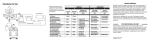
DIGITAL DECODER
Acknowledgement & Trademark
Acknowledgment & Trademark
All contents are subject to change at any time without notice. No
responsibility is assumed for its use; or for infringements of patents
or other rights of third parties and no patent or license is implied
hereby. All trademarks are the property of their respective owners.
Manufactured under license from Dolby Laboratories. "Dolby",
"ProLogic " and the double-D symbol are trademarks of Dolby
Laboratories. Confidential Unpublished Works. (c)1992 - 1997
Dolby Laboratories, Inc. All rights reserved.
Manufactured under license from Digital Theater Systems, Inc. US
Pat. No. 5,451,942, 5,956,674, 5,974,380, 5,978,762 and other
world-wide patents issued and pending. “DTS” and “DTS Digital
Surround” are registered trademarks of Digital Theater Systems, Inc.
Copyright 1996, 2000 Digital Theater Systems, Inc. All Rights
Reserved.
Sony and PlayStation? are trademarks of Sony Corporation.
Nintendo? is a trademark of Nintendo America, Inc.
FCC Compliance Statement
The equipment has been tested and found to comply with the limits for a Class B digital
device, pursuant to Part 15 of the FCC Rules. These limits are designed to provide
reasonable protection against harmful interference in residential installation. This
equipment generates, uses, and can radiate radio frequency energy and, if not installed and
used in accordance with the instructions, may cause harmful interference to radio
communications. However, there is no guarantee that interference will not occur in a
particular installation. If this equipment does cause interference to radio or television
reception, which can be determined by turning the equipment off and on. The user is
encouraged to try to correct the interference by one or more of the following measures:
1
?? Reorient or relocate the receiving antenna.
?? Increase the separation between the equipment and receiver.
?? Connect the equipment into an outlet on a circuit different from that to which the
receiver is connected.
?? Consult your dealer or an experienced radio/TV technician for help.
Notice
This device complies with Part 15 of the FCC rules. Operation is subject to the following two
conditions: (1) this device may not cause harmful interference, and (2) this device must
accept any interference received, including interference that may cause undesired operation.
Shielded cables and I/O cords must be used for this equipment to comply with the relevant
FCC regulations.
2
Table of Contents
Introduction ----------------------------------------------------------------- 4
Checking Package Contents --------------------------------------------------- 4
M6 501P Features ----------------------------------------------------------- 5
Important Safety Instructions -------------------------------------------------- 5
Installation ------------------------------------------------------------------ 6
M6 501P Front Panel --------------------------------------------------------- 7
M6 501P Rear Panel --------------------------------------------------------- 8
Connecting M6 501P (with External Power Amplifier) ----------------------------- 9
Connecting M6 501P (to the Klegg M6 501R Theater System) --------------------- 10
M6 501P Remote Control ----------------------------------------------------- 12
M6 501P Operation
LCD & LEDs ------------------------------------------------------------------------- 13
LCD Display ------------------------------------------------------------------------- 14
Mode Selection ---------------------------------------------------------------------- 14
Input Selection ----------------------------------------------------------------------- 15
Test Mode --------------------------------------------------------------------------- 16
Mute Mode -------------------------------------------------------------------------- 17
Master Volume Control --------------------------------------------------------------- 17
Balance Setting ---------------------------------------------------------------------- 18
Delay Calibration --------------------------------------------------------------------- 19
Time Delay Adjustment of Center Channel Speaker ------------------------------------- 20
Time Delay Adjustment of Surround Speakers ------------------------------------------ 21
Pro Logic Mode ---------------------------------------------------------------------- 22
Speaker Mode with Bass Manager ------------------------------------------------------ 23
Saving Presets ----------------------------------------------------------------------- 25
Loading Presets ---------------------------------------------------------------------- 26
Sound Field Processing -------------------------------------------------------------- 27
Equalization -------------------------------------------------------------------------- 28
DRC (Dynamic Range Compression) -------------------------------------------------- 29
Resetting ---------------------------------------------------------------------------- 30
Troubleshooting -------------------------------------------------------------- 31
Warranty ------------------------------------------------------------------- 32
In case of an insurance claim, please make sure you record the Model Number and Serial
Number printed on the real panel of the cabinet. The space below is provided this
information.
Model Number:
Serial Number:
Purchase Date:
Dealer Name:
3
Introduction
Thank you for purchasing the Klegg M6 501P Surround Sound Decoder. This versatile audio
surround sound system has been precisely designed to bring you the most advanced
surround modes including DTS, Dolby Digital & Dolby Pro Logic. This system will reproduce
six discrete channels of encoded sound tracks with true fidelity and sonic excellence. The
M6 501P automatically detects the type of signal present at each input and decodes it based
on the original encoded software. The M6 501P allows you to connect virtually any audio
input source such as TV, VCR, CD-ROM, DVD Player, LD Player, Stereo Receiver, PC and
Game Consoles (Nintendo? , Sony PlayStation? , and SEGA? ). The Klegg M6 501P is a
truly a dynamic multimedia theater center.
Checking Package Contents
Carefully unpack the Klegg M6 501P Surround Sound Decoder from the package and locate
its contents.
M6 501P Surround Sound Decoder
x1
M6 501P Owner’s Manual
x1
M6 501P Remote Control
x1
AC Adapter for Decoder (DC 12V, 1A)
x1
Note: Be sure to inspect the M6 501P for signs of damage resulting from shipping and
handling. If you notice any damage or find any items missing, please contact your local
dealer immediately.
4
M6 501P Features
- DTS
- Dolby Digital
- Dolby Pro Logic
- Bass Management
- Sound Field Processing
- Equalization
Important Safety Instructions
To ensure your safety, please read these instructions before operating this unit.
1.
Note all instructions and warnings marked on the unit.
2.
Always use the correct line voltage. Please refer to page 6 and locate the correct power
requirement for your area. Please note that different operating voltages may require the
use of different adapters.
3.
Do not install the unit in an unventilated rack or directly above heat producing
equipment such as power amplifiers.
4.
Do not block the openings on either side of the case.
5.
To avoid shock or fire hazard, do not expose the unit to rain or moisture or operate it
where it will be exposed to water.
6.
Do not attempt to operate the unit if it has been dropped, damaged, exposed to liquids,
or if it exhibits a distinct change in performance indicating the need for inspection.
7.
Only qualified service personnel should open this unit.
8.
Removing covers will expose you to hazardous voltages.
9.
Do not overload wall outlets or extension cords as this can result in a risk of fire or
electrical shock.
10. Route power supply cords so that they are not likely to be trodden on or pinched by
items placed on or against them, paying particular attention to plug fittings at the wall
outlets and at the point at which they exit from the unit.
5
Safety Voltage Chart:
The following chart details the correct AC adapter for your country:
Input
Device
M6 501P
Output
Area
50/60 Hz
DC 12V, 1A
Japan
AC 120 V
60 Hz
DC 12V, 1A
North America/
Taiwan
AC 230 V
50 Hz
DC 12V, 1A
Europe/UK
Voltage
Frequency
AC 100 V
Installation
?? Turn off any electrical or computer device that you plan to connect to the M6 501P.
?? Carefully unpack the M6 501P and its accessories from the transit packaging.
?? Place the M6 501P on a flat, stable surface, preferably on a TV shelf or similar. Allow at
least 10cm clear on all sides of the unit for ventilation.
?? Locate the M6 501P near your source equipment so you can use the shortest possible
interconnect cables. Keep your M6 501P away from moisture sources such as open
windows and heat sources such as hot air ducts or radiators. Also, keep the unit away
from direct sunlight since it could interfere with the remote control sensor.
?? The M6 501P Surround Sound Decoder has been designed to be ultimately flexible
accepting both digital and analog audio signals from CD Players, VCR, DVD players, TV
monitor, Computer and Game Consoles (Nintendo N64, Sega Dream Cast, SONY
PlayStation II etc.)
?? The M6 501P can also be connected to an external amplifier, or the Klegg M6 501R
Amplified Home Theater Speaker System as detailed on page 9 and 10.
6
M6 501P Front Panel
1. The POWER Button
This button turns M6 501P ON or OFF.
2. The POWER Indicator
This LED lights up when you plug in DC-12V.
3. Speaker Configuration LEDs
Each LED represents the status of an individual channel. When a particular channel is
active, the LED lights up. A RED LED light means this particular channel has been set
to output a wide frequency range that contains bass signals between 20Hz to 120Hz. A
GREEN LED light means this particular channel does not contain the bass signal
between 20Hz to 120Hz. When connecting to the Klegg M6 501R Home Theatre
Speaker System the Subwoofer channel should be the only RED LED. All other
channels should be set to narrow frequency bandwidth and should display GREEN (see
page 23).
4. Front Panel Display
This display provides you with important information regarding system status and
settings. It is important to be familiar with all the indicators on the display in order to
ensure correct operation of the system.
7
M6 501P Real Panel
(c)
AUX 2
OUTPUT
G9
AUX 1
LINE
L
SL
C
L
L
L
R
SR
SW
R
R
R
S/PDIF
DC+12V
5
_
1
2
3
+
4
M6 501P Real Panel
1. G9 Audio Output:
This output feeds 6 channels audio signals; L (Front Left), R (Front Right), SL
(Surround Left), SR (Surround Right), C (Center) & SW (Subwoofer) to the matching
inputs on a control center or power amplifier via G9 (DIN) cable.
2. Main Outputs:
The Six outputs feed audio signals to the matching inputs on a control center or
power amplifier.
L (Front Left)
R (Front Right)
SL (Surround Left)
SR (Surround Right)
C (Center)
SW (Subwoofer)
3. Auxiliary and Line Inputs:
These inputs accept signals from stereo analog signal sources.
4. S/PDIF Digital Inputs:
M6 501P accepts two types of digital inputs. One optical input and another coaxial
input. Connect the digital outputs of the sound sources to these inputs.
5. DC 12V Power Input:
Connect the M6 501P’s adapter to an AC outlet. Please refer to page 6 to determine
the correct voltage in your area.
8
Connecting M6 501P (with External Power Amplifier)
CD player
Game Consoles
DVD Player
Coaxial
digital Output
Audio Out
Audio Out
L
Digital
L
Audio Out
L
L
Coaxial
R
Phone Jack
Play
R
R
OUTPUT
G9
R
Optical
Rec
AUX 2
AUX 1
LINE
L
SL
C
L
L
L
R
SR
SW
R
R
R
S/PDIF
L
SL
C
SR
R
Input
Output
+ _
Left
+ _
Surround
Left
+ _
+ _
Center Surround
Right
9
DC+12V
External
Amplifier
+ _
Right
Powered
Subwoofer
Connecting M6 501P (with the Klegg M6 501R Theater System)
10
1.
After properly connecting M6 501P to your audio sources and amplifier, plug in M6
501P’s AC adapter to an AC outlet.
2.
Activate the M6 501P power by pushing the POWER Button on the front panel. Then, turn
on the power for all audio sources, amplifier, and/or powered subwoofer.
3.
Having completed the installation, get ready to experience true Dolby Digital or DTS
surround sound right in your living room.
Note:
When playing music or movies be sure to have the volume set low initially. Gradually turn
the volume up to an appropriate level after the playback has started.
EQ Band Settings for the Klegg M6 501R Home Theatre Speaker System
The M6 501P allows precise adjustment of equalizer band settings (see page 28). Since each
speaker system has its own individual properties, you may wish to experiment with these
settings to attain your desired output reproduction. If you are connecting the M6 501P to the
Klegg M6 501R Home Theatre Speaker System, you may wish to start with an EQ Setup as
follows:
??
BAND 1: +8dB
??
BAND: 2 +9dB
??
BAND: 3 +7dB
??
BAND: 4 +8dB
??
BAND: 5 +9dB
These are settings are for general guidance only. The acoustics of your own living room and
desired listening levels will mean your own set up will provide the best results.
11
M6 501P Remote Control
6
9 6
power
2
1
7
mute
4
balance
delay
prologic
field
EQ on/off
EQ setup
preset 1
preset 2
preset 3
5
7
10
3
8
11
save
preset 4
13
Cen
15
14
DRC
9
load
12
SL/SR
8
10
SW
VOL
11
D Time
18
19
17
16
12
13
14
1.
2.
3.
4.
5.
POWER Button
On/Off key.
INPUT MODE Button
Select from 5 different
source inputs.
TEST Button
5.1 channel test tone
activation.
MUTE Button
Temporarily disable
signal output.
PROLOGIC Button
Select up to 4 different surround
ettings.
15
16
17
18
19
DELAY Button
Select the desired channel to adjust the time
Delay.
BALANCE Button
Volume settings for all 6 channels.
EQ SETUP Button
Select up to 5 EQ Band Settings* (see page 11).
EQ ON/OFF Button
Activate the selected EQ Band Setting.
FIELD Button
Choose from 6 different sound fields.
PRESET Button (P1, P2, P3, P4)
Store up to 4 different user settings.
SAVE Button
Store user settings into a selected preset.
LOAD Button
Activate user settings stored in selected preset.
SPEAKER ON/OFF Buttons (CEN, SL/SR, SW)
These 3 buttons switch the center speakers,
SL/SR speakers and subwoofer on and off.
CEN Button allows you to activate/deactivate
the center channel speaker.
LS/RS Button lets you simultaneously
activate/deactivate the left and right surround
speakers.
SW Button is used to activate/deactivate the
subwoofer.
BASS MANAGER Button
Switches among three bass configurations (bass
config. 1, bass config. 2 and bass config. 3).
VOL + and VOL –
Increase/decrease the volume.
D TIME Button
Increase/decrease the delay time.
DRC Button
Choose from 3 different compression ratios of
the dynamic range.
RESET Button
Press this button to reset the system to its
factory default settings.
12
M6 501P Operation
In the following pages we have provided detailed operation explanations to guide you through
the proper setup and operation of the M6 501P. As you might have noticed, there is only a
POWER ON/OFF button on the front panel. The M6 501P has been purposely designed for
user-friendly remote control operation. All functions and settings of the M6 501P are operated
from the remote control.
M6 501P Operation – LCD and LEDs
1. Press the power button to turn the M6 501P on, press it again to turn it off.
2. When power is turned off using the power button the M6 501P will do the following:
a. Both LCD display and Speaker Configuration LEDs will switch off.
b. Power indicator LED will remain on.
c. Decoder status and user configurations will be memorized.
d. Once the power is turned on again the M6 501P will resume to its previous decoder
status and user configurations.
3. When power is turn off from the mains supply the M6 501P will do the following:
a. LCD display, Power Indicator LED and Speaker Configuration LEDs will switch off.
b. Decoder status and user configurations will be lost.
c. The M6 501P will reset to factory default settings at resumption of power supply.
13
M6 501P Operation – LCD Display
Auto Decode Mode (Auto Detect Input Stream Type)
When the M6 501P is turned on it automatically detects and differentiates the audio signal
coming from source unit.
Playing a DVD with Dolby Digital (AC3) encoding will display the following information:
D o l b y
D i g i t a l
C o
S U R R O U N D
Playing a DVD with DTS encoding will display the following information:
D T S
C O A X I A L
S U R R O U N D
Playing a DVD, CD, LD, VCR and Games with analog outputs connected to the analog inputs
(LINE, AUX1 & AUX2) of the M6 501P will display the following information:
P C M
L I N E I N
S T E R E O
M6 501P Operation – Mode Selection
Surround Processing Modes:
The versatile Klegg M6 501P surround sound processor is capable of processing both the
digital and analog audio signals from today’s A/V equipment. Ensure all equipment is
connected properly and the M6 501P will automatically detect the type of digital signal present
at the appropriate digital input.
14
M6 501P Operation – Input Selection
Input Selection
power
The M6 501P can be connected up to 5 audio sources.
Select the input source feeding the M6 501P by
mute
balance
delay
prologic
field
EQ on/off
EQ setup
preset 1
preset 2
preset 3
repeatedly pressing the INPUT Button on the remote
control until the desired setting is reached.
In the Digital Mode (Dolby Digital / DTS) you can manually select the digital audio input
source from either the coaxial or optical input depending on the type of audio output source.
If “COAXIAL” is selected the M6 501P will display the following information:
D o l b y
D i g i t a I
C o
S U R R O U N D
If “Optical” is selected the M6 501P will display the following information:
D o l b y
D i g i t a I
O p
S U R R O U N D
In the PCM mode, you can choose from 3 sets of audio input sources such as CD Player, VCR,
game consoles etc. (See page 8 or page 9 for reference). The M6 501P will display the
following information:
P C M
S T E R E O
L I N E I N
P C M
S T E R E O
A U X 1
P C M
S T E R E O
A U X 2
15
M6 501P Operation – Test Mode
Test Mode
After completing the installation, press the TEST Button
on the remote to see if the system functions properly.
power
the speakers. When the TEST Button is pressed, white
mute
balance
field
preset 1
You can also use the test mode to test the location of
delay
EQ on/off
prologic
EQ setup
preset 2 preset 3
noise is emitted through all the satellite speakers in the
order of L, C, R, SL, and SR channels for 2 seconds
each. When completed the M6 501P returns to Auto
Decode mode.
When Test Mode is activated the M6 501P will display the following information in the
following sequence:
D o l b y
D i g i t a I
T E S T
L
C o
D o l b y
D i g i t a I
T E S T
C
C o
D o l b y
D i g i t a I
T E S T
R
C o
D o l b y
D i g i t a I
T E S T
S L
C o
D o l b y
D i g i t a I
T E S T
S R
C o
16
M6 501P Operation – Mute Mode
Mute Mode
Pressing MUTE Button on the remote control
power
6 RCA connectors.)
mute
balance
field
preset 1
interrupts all signal outputs (including the G9 and
delay
EQ on/off
prologic
EQ setup
preset 2 preset 3
To disable the mute function press MUTE Button
again.
When the MUTE Button is pressed the M6 501P will display the following information:
D o l b y
D i g i t a I
C o
S U R R O U N D
M U T E
M6 501P Operation – Master Volume Control
Volume Setting
Cen
SL/SR
DRC
SW
VOL
D Time
To increase or decrease the Master Volume of the
M6 501P simply press VOL + or VOL - on the
remote control.
For example: if the volume is reduced by 3 decibels the M6 501P will display the following
information:
D o l b y
D i g i t a I
V O L U M E
- 0 3 d B
17
C o
M6 501P Operation – Balance Setting
Balance
Balance Button
balance
delay
prologic
field
EQ on/off
EQ setup
preset 1
preset 2
preset 3
save
preset 4
load
Cen
SL/SR
DRC
SW
VOL
D Time
Users can customize the volume setting of each
individual channel.
To select a channel press the BALANCE Button on
the remote control. Press this button repeatedly
until desired channel is selected.
Adjust volume on selected channel by pressing
VOL + or VOL - on the remote control.
Example:
Press the BALANCE Button and the M6 501P will display the current balance volume for
channel L:
D o l b y
D i g i t a I
B A L A N C E
L
0
C o
d B
Press the BALANCE Button again and the M6 501P will cycle to next channel:
D o l b y
D i g i t a I
B A L A N C E
R
0
C o
d B
Pressing VOL + or VOL - will increase or decrease the balance volume for selected
channel:
D o l b y
D i g i t a I
C o
B A L A N C E
R
+ 0 1 d B
18
M6 501P Operation – Delay Calibration
SW
C
TV
L
SL
R
SR
The ideal listening position is defined below:
?? Center channel speaker should be placed in a position that has an equal distance as the
left and right speakers to listener.
?? Surround left and surround right speakers should be placed behind the listener and above
listener’s ear level.
?? If speaker placement is restricted due to the physical environment of the room, delay
calibration maybe necessary to achieve the ideal listening environment.
?? If the center speaker only can be placed in a position that is closer to the listener than that
of the left and right speakers, the sound from the center speaker will be out of
synchronization with front left and front right. This difference in sound arrival time will
negatively affect the quality of the home theatre experience, even on the best DVD titles.
?? Fortunately the M6 501P allows you to adjust the center speaker time delay to
compensate for this problem by increasing the delay time for the center channel allowing
sound from the center, left and right speakers reach the listener at the same time. If your
center speaker is closer to the listening position than the left and right speakers, press the
DELAY Button repeatedly until the Center channel is reached. To increase or decrease the
delay time press D TIME + or D TIME - until the required distance is matched.
?? The same procedure can be applied for adjusting the delay time of surround speakers if
necessary.
19
M6 501P Operation – Time Delay Adjustment of Center Channel Speaker
Delay Calibration
balance
field
preset 1
save
delay
EQ on/off
prologic
EQ setup
preset 2 preset 3
preset 4
load
Cen
SL/SR
DRC
SW
VOL
Press the DELAY Button to select the length of
delay time for SL/SR/C channels. Repeatedly
pressing the DELAY Button will allow you to
choose from the 3 surround speakers (SL, SR, C.)
D Time
The delay time range for SL/SR is 0 to 15 ms and
0 to 5 ms for Center.
Adjust the delay time on the selected channel by
pressing D TIME + or D TIME - on the remote
control.
Press the DELAY Button and the M6 501P will display the current delay time for channel LS.
D o l b y
D E L A Y
D i g i t a I
C o
S L
5
m s
Press the DELAY Button again and the M6 501P will cycle to next channel.
D o l b y
D E L A Y
D i g i t a I
C o
S R
5
m s
Press the D TIME + or D TIME - button and the M6 501P will increase or decrease the delay
time for the current channel.
D o l b y
D E L A Y
D i g i t a I
C o
S R
6
ms
20
M6 501P Operation – Time Delay Adjustment on Surround Speakers
Delay Calibration
balance
field
preset 1
save
delay
EQ on/off
prologic
EQ setup
preset 2 preset 3
preset 4
load
Cen
SL/SR
DRC
SW
VOL
Press DELAY Button to select the length of delay
time for SL/SR/C channels. Repeatedly pressing
the DELAY Button will allow you to select the 3
surround speakers (SL, SR, C.)
The delay time range for SL/SR is 0 to 15 ms and
0 to 5 ms for Center.
D Time
Adjust the delay time on the selected channel by
pressing D TIME + or D TIME - on the remote
control.
Surround Speaker Delay
Delay calibration for the surround speakers is necessary when the surround speakers are
placed close to the listening position. Placing surround speakers too close to the listing
position without adjusting the delay time will significantly reduce the quality of your movie
soundtrack. To correct this problem, press the DELAY Button repeatedly until SL/SR appears on
the display. Increase the time delay of the surround speakers by pressing D TIME + until you
are able to hear a 3D sound effect coming from surround speakers.
Press the DELAY Button again and the M6 501P will cycle to next channel:
D o l b y
D i g i t a I
C o
D E L A Y
S L
5
m s
D o l b y
D E L A Y
D i g i t a I
C o
S R
5
m s
Pressing D TIME + or D TIME - will increase or decrease the delay time for the selected
channel:
D o l b y
D E L A Y
D i g i t a I
C o
S R
6
ms
21
M6 501P Operation – Pro Logic Mode
Pro Logic Mode
power
mute
balance
delay
prologic
field
EQ on/off
EQ setup
preset 1
preset 2
preset 3
Your M6 501P will automatically switch to Pro Logic
mode when it detects the Pro Logic signal. With
other signal inputs you can select the Dolby Pro
Logic mode by pressing Prologic Button on the
remote. Repeatedly pressing the Prologic Button will
cycle the Pro Logic mode in the order of: “AUTO”,
“ALL PCM”, “ENABLE” and “DISABLE ”.
If a Pro Logic signal is detected the M6 501P will switch to Pro Logic mode automatically and
the following information is displayed:
D o l b y
D i g i t a I
P R O L O G I C
A U T O
C o
If a Stereo signal (either in analog or in digital form) is detected the M6 501P will switch to
Stereo mode automatically. You can then convert the stereo signal to Pro Logic mode by
pressing the Prologic Button until the display reads as follows:
D o l b y
D i g i t a I
C o
P R O L O G I C
A L L
P C M
or
D o l b y
D i g i t a I
C o
P R O L O G I C
E N A B L E
In the case of converting a Pro Logic or 2-channel Dolby Digital signal into Stereo mode, press
the Prologic Button until the display reads as follows:
D o l b y
D i g i t a I
C o
P R O L O G I C
D I S A B L E
22
M6 501P Operation – Speaker Mode with Bass Manager
Speaker Mode with Bass Manager
save
preset 4
load
Cen
SL/SR
DRC
SW
VOL
D Time
The six LEDs on the front panel of the M6 501P
represent 6 audio channels: L, R, C, SL, SR, SW
(otherwise known as 5.1). If a particular channel
is active in narrow bandwidth mode the LED will
light up in GREEN. A RED colour LED means that
the particular channel also carries bass signals
below 120Hz.
If you have small satellite speakers, ensure
Speaker Mode indicates GREEN for the
necessary speakers. RED is only for speakers
capable of signals below 120Hz.
Speaker Mode
By pressing the CEN Button the center channel will be switched on/off and the LCD will display
following the information:
D o l b y
S P K
C
D i g i t a I
O N
C o
D o l b y
S P K
C
D i g i t a I
O F F
C o
By pressing the SL/SR Button the surround channels will be switched on/off and the LCD will
display the following information:
D o l b Y
D i g i t a I
S P K
S U R
O N
D o l b y
D i g i t a I
S P K
S U R
O F F
23
C o
C o
By pressing the SW Button the subwoofer will be switched on/off and the LCD will display the
following information:
D o l b y
D i g i t a I
S P K
S W
O N
D o l b y
D i g i t a I
S P K
S W
O F F
C o
C o
Bass Manager
By pressing the BASS MANAGER Button you can choose from three different settings of: Bass
Config.1, Bass Config.2 and Bass Config.3. These selections will feed bass signals below
120Hz to the appropriate speakers.
Bass Config. 1
With this setting bass signals below 120Hz will be sent to subwoofer. The LED on the front
panel of the M6 501P indicating SW will be in red and the LCD will show the following
information:
D o l b y
D i g i t a I
B A S S
C O N F I G . 1
C o
Bass Config. 2
With this setting bass signals below 120Hz will be sent to front left speaker, front right speaker
and subwoofer. The LEDs on the front panel of M6 501P indicating L/R/SW will be in red, and
LCD will show the following information:
D O l b y
D i g i t a I
B A S S
C O N F I G . 2
C O
Bass Config. 3
With this setting bass signals below 120Hz will be sent to all speakers. The LEDs on the front
panel of M6 501P indicating L/R/SL/SR/SW channels will be in red.
D o l b y
D i g i t a I
B A S S
C O N F I G . 3
C o
Bass Config. Off
With this setting bass signals below 120Hz will be sent to all speakers. The LEDs on the front
panel of the M6 501P indicating L/R/C/SL/SR/SW channels will all be in red.
D o l b y
D i g i t a I
C o
B A S S
C O N F I G . O F F
24
M6 501P Operation – Saving Presets
Setting Presets
mute
balance
field
preset 1
save
delay
EQ on/off
prologic
EQ setup
preset 2 preset 3
preset 4
The M6 501P allows you to customize up to 4
settings. This function allows you to program, save
and load your favorite configurations at any time.
load
Cen
SL/SR
DRC
SW
VOL
D Time
Preset settings:
Pressing the PRESET 1 Button will display:
D o l b y
D i g i t a I
P R E S E T
1
C o
Press the SAVE Button to save all current decoder settings into Preset 1.
D o l b y
D i g i t a I
C o
P R E S E T
1
S a v i n g
D o l b y
D i g i t a I
C o
P R E S E T
1
S a v e d
When complete the M6 501P will shift back to Auto Decode mode.
D o l b y
D i g i t a I
C o
25
M6 501P Operation – Loading Preset
Loading Preset
field
EQ on/off
EQ setup
preset 1
preset 2
preset 3
save
preset 4
load
You can load a previously saved preset by
pressing LOAD Button on the remote.
Cen
SL/SR
SW
VOL
D Time
DRC
Preset 1:
Press any of the 4 preset buttons, (PRESET 1, PRESET 2, PRESET 3 or PRESET 4) and the
display will show the following information:
D o l b y
D i g i t a I
P R E S E T
1
C o
Press the LOAD Button to execute.
D o l b y
D i g i t a I
C o
P R E S E T
1
L O A D I N G
D o l b y
D i g i t a I
C o
P R E S E T
1
L O A D E D
When preset loading is completed the M6 501P reverts to Auto Decode mode.
D o l b y
D i g i t a I
C o
26
M6 501P Operation – Sound Field Processing
DSP Sound Field
The M6 501P is equipped with a sound field processor that
field
EQ on/off
preset 1
save
EQ setup
preset 2 preset 3
preset 4
load
Cen
SL/SR
SW
provides six different field effects including Disable, Hall,
Theater, Stadium, Club, and Church. By pressing the Field
Button on the remote you can select these effects.
Furthermore, you can increase or decrease the Reverb
value from 0 – 9 by pressing VOL + or VOL - on the
remote control.
Pressing the Field Button will display the current setting of the Sound Field mode.
D o l b y
D i g i t a I
C o
D I A B L E
R e v e r b
0
D o l b y
H A L L
D i g i t a I
C o
R e v e r b
3
D o l b y
D i g i t a I
C o
T H E A T E R
R e v e r b
3
D o l b y
D i g i t a I
C o
S T A D I U M
R e v e r b
3
D o l b y
C L U B
D i g i t a I
C o
R e v e r b
3
D o l b y
D i g i t a I
C o
C H U R C H
R e v e r b
3
27
M6 501P Operation – Equalization
5–Band Equalization
mute
balance
field
preset 1
save
delay
EQ on/off
prologic
EQ setup
preset 2 preset 3
preset 4
load
Cen
SL/SR
DRC
The M6 501P features an on board 5-band equalizer
which allows you to fine-tune the sound of your favorite
movie/music. Press the EQ SETUP Button on the
remote to activate. Repeatedly pressing the EQ SETUP
Button will cycle through the 5 bands.
Each band of the equalizer allows a ±10dB range of
volume adjustment. By pressing VOL + or VOL - on
the remote control you can achieve your desired
volume.
SW
VOL
D Time
After setting up the desired volume for each EQ bank
you
must press EQ SETUP Button again to enable the new
EQ setting.
Press the EQ ON/OFF Button to execute the new EQ
setting.
Pressing the EQ SETUP Button will display the current setting of EQ Band 1.
D o l b y
D i g i t a I
C o
E Q
B A N D
1
0 d B
Pressing the EQ SETUP Button again will cycle to the next EQ Band.
D o l b y
D i g i t a I
C o
E Q
B A N D
2
0 d B
Pressing the Vol+ or Vol- will increase or decrease the volume for the current EQ Band.
D o l b y
D i g i t a I
C o
E Q
B A N D
2
+ 0 1 d B
Press the EQ SETUP Button to enable the new EQ setting.
Press the EQ ON/OFF Button to execute the new EQ setting.
28
M6 501P Operation – DRC (Dynamic Range Compression)
DRC
save
preset 4
load
Cen
SL/SR
DRC
SW
VOL
D Time
The M6 501P features Dynamic Range
Compression (DRC). This sophisticated
technology creates realistic sound fields with rich,
detailed sound that is remarkably free from
distortion.
Repeatedly pressing DRC button will cycle through
3 modes as detailed below:
“NO” means no compression is performed to the
original audio signal. This gives the listener the
greatest dynamic range.
“HALF” means the audio signal is partially
compressed. This function is useful if the M6 501P
is connected to an external amplifier.
“FULL” means the audio signal is completely
compressed. This function is also useful if the M6
501P is connected to an external amplifier.
Press the DRC Button and the current setting of Dynamic Range Compression mode is
displayed:
D o l b y
D i g i t a I
D y n a m i c
C o
N O
Pressing the DRC Button again cycles through the DRC modes:
D o l b y
D i g i t a I
C o
D y n a m i c
F U L L
D o l b y
D i g i t a I
C o
D y n a m i c
H A L F
29
M6 501P Operation – Resetting
Resetting
Cen
SL/SR
DRC
SW
VOL
D Time
The M6 501P can be reset to its default settings
by pressing the RESET Button on the remote.
Pressing the RESET Button will reset the M6 501P to its factory default settings:
D o l b y
R E S E T
D i g i t a I
C o
t o
F a c t o r Y
When the reset is completed the M6 501P reverts to Auto Decode mode:
D o l b y
D i g i t a I
S U R R O U N D
30
C o
Troubleshooting
This section is designed to help you solve possible problems you might encounter. Common
questions and answers regarding installation and connection are listed below for your
reference. In case these pointers do not solve the problem please contact your dealer or Klegg
Customer Enquiries for further assistance.
Problem
No Sound
Cause
Speaker not properly connected
Remedy
Check cables for shorts
or open connections
Incorrect input mode
Select proper audio
source (Digital or
Analog)
Amplifier is off/malfunction
Check your amplifier
Speaker defective
Refer to speaker
documentation
Turn up volume control
Weak sound
Volume control down
Check cables
Buzzing sound
Speaker cable shorted or has
broken strands
Speaker cable (wire) shorted
Mains power interference
Check power cable is not
running next to speaker
cables. Connect power
adapter to different wall
socket.
Defective speaker
Refer to speaker
documentation
Adjust balance control
Check speaker
connections
No balance control
Excessive
highs or lows
Check balance control setting
Speaker out of circuit
31
Check cable wiring
Warranty
Your Klegg M6 501P Surround Sound Processor comes with a one-year warranty from the
date of purchase. This warranty does not cover any incompatibilities due to the user’s
hardware or any other related system configuration in which the M6 501P interfaces.
This warranty does not cover any damage caused by negligence, non-authorized
modifications, or parts installed.
This warranty will not be valid if the product has been damaged by accident, abuse, misuse,
or misapplication, nor as a result of servicing by anyone other than by the manufacturer or
authorized personnel.
When you send in your product for service, make sure it is adequately cushioned to prevent
damage during shipping. Include all components and accessories that came with your M6
501P so that the integrity of these pieces can also be verified by service center.
Note: It is recommended that you ship your M6 501P fully insured and freight pre-paid.
Units will not be accepted if they are damaged by poor handling during transit.
32