1
TH-D72A/ TH-D72E
144/440 MHz FM DUAL BANDER/
144/430 MHz FM DUAL BANDER
INSTRUCTION MANUAL
144/440 MHz FM DOUBLE BANDE/
144/430 MHz FM DOUBLE BANDE
MODE D’EMPLOI
DOBLE BANDA DE 144/440 MHz EN FM/
DOBLE BANDA DE 144/430 MHz EN FM
MANUAL DE INSTRUCCIONES
Only basic operations are explained in this instruction manual.
For a detailed explanation on the operations, refer to the PDF file
supplied on the CD-ROM.
Seules les fonctions de base sont expliquées dans ce mode
d’emploi. Pour le détail sur les autres opérations, reportez-vous
au fichier PDF à votre disposition sur le CD-ROM.
En este manual de instrucciones solamente se explican las
operaciones básicas. Si desea obtener una descripción detallada
de las operaciones, consulte el archivo PDF correspondiente
incluido en el CD-ROM.
© B62-2235-10 (K, E)
09 08 07 06 05 04 03 02 01
144/440 MHz FM DUAL BANDER/
144/430 MHz FM DUAL BANDER
ENGLISH
TH-D72A/ TH-D72E
INSTRUCTION MANUAL
NOTIFICATION
This equipment complies with the essential requirements of Directive
1999/5/EC.
The use of the warning symbol
means the equipment is subject to
restrictions of use in certain countries.
This equipment requires a licence and is intended for use in the
countries as below.
AT
IE
SE
LT
BE
IT
CH
MT
DK
LI
GB
PL
FI
LU
CY
SK
FR
NL
CZ
SI
DE
NO
EE
BG
GR
PT
HU
RO
IS
ES
LV
ISO3166
7+$1.<28
We are grateful you decided to purchase this Kenwood FM transceiver.
Kenwood always provides Amateur Radio products which surprise and excite
serious hobbyists. This transceiver is no exception. Kenwood believes that this
product will satisfy your requirements for both voice and data communications.
The models listed below are covered by this manual.
TH-D72A: 144/440 MHz FM Dual Bander (The Americas)
TH-D72E: 144/430 MHz FM Dual Bander (Europe)
)($785(6
This transceiver has the following main features:
•
•
•
•
•
•
A built-in GPS receiver unit.
A built-in 5,000 point GPS Logger.
A built-in TNC which conforms to the AX.25 protocol. With a portable computer, it
allows you to easily enjoy Packet operation.
Includes a program for dealing with data formats supported by Automatic Packet
Reporting System (APRS®).
Contains a total of 1000 Memory channels to program frequencies and other various
data. Each Memory channel can be named using up to 8 alphanumeric characters.
Continuous Tone Coded Squelch System (CTCSS) or Digital Coded Squelch (DCS)
rejects unwanted calls from other stations.
:5,7,1*&219(17,216)2//2:(',17+,60$18$/
The writing conventions described below have been followed to simplify
instructions and avoid unnecessary repetition.
Instruction
Action
Press [KEY].
Momentarily press KEY.
Press [KEY] (1s).
Press and hold KEY for 1 second or longer.
Press [KEY1], [KEY2].
Press KEY1 momentarily, release KEY1, then press
KEY2.
Press [F], [KEY].
Press the F key to enter Function mode, then press
KEY to access its secondary function.
Press [KEY] + Power ON.
With the transceiver power OFF, press and hold
KEY while turning the transceiver power ON.
Information on Disposal of Old Electrical and Electronic Equipment and Batteries (applicable
for EU countries that have adopted separate waste collection systems)
Products and batteries with the symbol (crossed-out wheeled bin) cannot be
disposed as household waste.
Old electrical and electronic equipment and batteries should be recycled at a facility
capable of handling these items and their waste byproducts. Contact your local
authority for details in locating a recycle facility nearest to you. Proper recycling and
waste disposal will help conserve resources whilst preventing detrimental effects on
our health and the environment.
NOTICES TO THE USER
One or more of the following statements may be applicable:
FCC WARNING
This equipment generates or uses radio frequency energy. Changes or modifications to this
equipment may cause harmful interference unless the modifications are expressly approved in the
instruction manual. The user could lose the authority to operate this equipment if an unauthorized
change or modification is made.
INFORMATION TO THE DIGITAL DEVICE USER REQUIRED BY THE FCC
This equipment has been tested and found to comply with the limits for a Class B digital device,
pursuant to Part 15 of the FCC Rules. These limits are designed to provide reasonable protection
against harmful interference in a residential installation.
This equipment generates, uses and can generate radio frequency energy and, if not
installed and used in accordance with the instructions, may cause harmful interference to radio
communications. However, there is no guarantee that the interference will not occur in a particular
installation. If this equipment does cause harmful interference to radio or television reception,
which can be determined by turning the equipment off and on, the user is encouraged to try to
correct the interference by one or more of the following measures:
• Reorient or relocate the receiving antenna.
• Increase the separation between the equipment and receiver.
• Connect the equipment to an outlet on a circuit different from that to which the receiver is
connected.
• Consult the dealer for technical assistance.
WHEN CONDENSATION OCCURS INSIDE THE TRANSCEIVER
Condensation may occur inside the transceiver in such a case where the room is warmed using
a heater on cold days or where the transceiver is quickly moved from a cold room to a warm room.
When condensation occurs, the microcomputer and/or the transmit/receive circuits may become
unstable, resulting in transceiver malfunction. If this happens, turn OFF the transceiver and just
wait for a while. When the condensation droplets disappear, the transceiver will function normally.
ATTENTION: (USA only)
The RBRC Recycle seal found on Kenwood lithium-ion (Li-ion) battery packs
indicates Kenwood’s voluntary participation in an industry program to collect and
recycle Li-ion batteries after their operating life has expired. The RBRC program is
an alternative to disposing Li-ion batteries with your regular refuse or in municipal
waste streams, which is illegal in some areas.
For information on Li-ion battery recycling in your area, call (toll free)
1-800-8-BATTERY (1-800-822-8837).
Kenwood’s involvement in this program is part of our commitment to preserve our environment and conserve
our natural resources.
This product contains a CR Coin Cell Lithium Battery which contains Perchlorate Material – special
handling may apply.
See www.dtsc.ca.gov/hazardouswaste/perchlorate
i
35(&$87,216
•
•
Do not charge the transceiver and battery pack when they are wet.
Ensure that there are no metallic items located between the transceiver and the battery
pack.
Do not use options not specified by Kenwood.
If the die-cast chassis or other transceiver part is damaged, do not touch the damaged
parts.
If a headset or headphone is connected to the transceiver, reduce the transceiver
volume. Pay attention to the volume level when turning the squelch off.
Do not place the microphone cable around your neck while near machinery that may
catch the cable.
Do not place the transceiver on unstable surfaces.
Ensure that the end of the antenna does not touch your eyes.
When the transceiver is used for transmission for many hours, the radiator and chassis
will become hot. Do not touch these locations when replacing the battery pack.
Do not immerse the transceiver in water.
Always switch the transceiver power off before installing optional accessories.
For safety reasons, we recommend that the AC adapter (for the battery charger) be
connected to an easily accessible AC socket.
•
•
•
•
•
•
•
•
•
•
Turn the transceiver power off in the following locations:
• In explosive atmospheres (inflammable gas, dust particles, metallic powders, grain
powders, etc.).
• While taking on fuel or while parked at gasoline service stations.
• Near explosives or blasting sites.
• In aircrafts. (Any use of the transceiver must follow the instructions and regulations
provided by the airline crew.)
• Where restrictions or warnings are posted regarding the use of radio devices,
including but not limited to medical facilities.
• Near persons using pacemakers.
•
•
•
•
•
•
ii
Do not disassemble or modify the transceiver for any reason.
Do not place the transceiver on or near airbag equipment while the vehicle is
running. When the airbag inflates, the transceiver may be ejected and strike the
driver or passengers.
Do not transmit while touching the antenna terminal or if any metallic parts are
exposed from the antenna covering. Transmitting at such a time may result in a
high-frequency burn.
If an abnormal odor or smoke is detected coming from the transceiver, switch the
transceiver power off immediately, remove the battery pack from the transceiver, and
contact your Kenwood dealer.
Use of the transceiver while you are driving may be against traffic laws. Please
check and observe the vehicle regulations in your area.
Do not expose the transceiver to extremely hot or cold conditions.
•
•
•
Do not carry the battery pack (or battery case) with metal objects, as they may short
the battery terminals.
When operating the transceiver in areas where the air is dry, it is easy to build up
an electric charge (static electricity). When using a earphone accessory in such
conditions, it is possible for the transceiver to send an electric shock through the
earphone and to your ear. We recommend you use only a speaker/microphone in
these conditions, to avoid electric shocks.
Do not swing the transceiver around while holding onto the strap. Doing so may
cause injury to other persons and damage to the transceiver.
Information concerning the battery pack:
The battery pack includes flammable objects such as organic solvent.
Mishandling may cause the battery to rupture producing flames or extreme heat,
deteriorate, or cause other forms of damage to the battery. Please observe the
following prohibitive matters.
•
•
•
•
•
•
•
Do not disassemble or reconstruct battery!
The battery pack has a safety function and protection circuit to avoid danger. If they
suffer serious damage, the battery may generate heat or smoke, rupture, or burst
into flame.
Do not short-circuit the battery!
Do not join the + and – terminals using any form of metal (such as a paper clip or
wire). Do not carry or store the battery pack in containers holding metal objects (such
as wires, chain-necklace or hairpins). If the battery pack is short-circuited, excessive
current will flow and the battery may generate heat or smoke, rupture, or burst into
flame. It will also cause metal objects to heat up.
Do not incinerate or apply heat to the battery!
If the insulator is melted, the gas release vent or safety function is damaged, or the
electrolyte is ignited, the battery may generate heat or smoke, rupture, or burst into
flame.
Do not leave the battery near fire, stoves, or other heat generators (areas
reaching over 80°C/ 176°F)!
If the polymer separator is melted due to high temperature, an internal short-circuit
may occur in the individual cells and the battery may generate heat or smoke,
rupture, or burst into flame.
Do not immerse the battery in water or get it wet by other means!
If the battery’s protection circuit is damaged, the battery may charge at extreme
current (or voltage) and an abnormal chemical reaction may occur. The battery may
generate heat or smoke, rupture, or burst into flame.
Do not charge the battery near fire or under direct sunlight!
If the battery’s protection circuit is damaged, the battery may charge at extreme
current (or voltage) and an abnormal chemical reaction may occur. The battery may
generate heat or smoke, rupture, or burst into flame.
Use only the specified charger and observe charging requirements!
If the battery is charged in unspecified conditions (under high temperature over the
regulated value, excessive high voltage or current over regulated value, or with a
remodeled charger), it may overcharge or an abnormal chemical reaction may occur.
The battery may generate heat or smoke, rupture, or burst into flame.
iii
•
•
•
•
•
•
•
•
•
•
•
iv
Do not pierce the battery with any object, strike it with an instrument, or step
on it!
This may break or deform the battery, causing a short-circuit. The battery may
generate heat or smoke, rupture, or burst into flame.
Do not jar or throw the battery!
An impact may cause the battery to leak, generate heat or smoke, rupture, and/or
burst into flame. If the battery’s protection circuit is damaged, the battery may charge
at an abnormal current (or voltage), and an abnormal chemical reaction may occur.
The battery may generate heat or smoke, rupture, or burst into flame.
Do not use the battery pack if it is damaged in any way!
The battery may generate heat or smoke, rupture, or burst into flame.
Do not solder directly onto the battery!
If the insulator is melted or the gas release vent or safety function is damaged, the
battery may generate heat or smoke, rupture, or burst into flame.
Do not reverse the battery polarity (and terminals)!
When charging a reversed battery, an abnormal chemical reaction may occur. In
some cases, an unexpected large amount of current may flow upon discharging.
The battery may generate heat or smoke, rupture, or burst into flame.
Do not reverse-charge or reverse-connect the battery!
The battery pack has positive and negative poles. If the battery pack does not
smoothly connect with a charger or operating equipment, do not force it; check the
polarity of the battery. If the battery pack is reverse-connected to the charger, it will
be reverse-charged and an abnormal chemical reaction may occur. The battery may
generate heat or smoke, rupture, or burst into flame.
Do not touch a ruptured and leaking battery!
If the electrolyte liquid from the battery gets into your eyes, wash your eyes with
fresh water as soon as possible, without rubbing your eyes. Go to the hospital
immediately. If left untreated, it may cause eye-problems.
Do not charge the battery for longer than the specified time!
If the battery pack has not finished charging even after the regulated time has
passed, stop it. The battery may generate heat or smoke, rupture, or burst into
flame.
Do not place the battery pack into a microwave or high pressure container!
The battery may generate heat or smoke, rupture, or burst into flame.
Keep ruptured and leaking battery packs away from fire!
If the battery pack is leaking (or the battery emits a bad odor), immediately remove it
from flammable areas. Electrolyte leaking from battery can easily catch on fire and
may cause the battery to generate smoke or burst into flame.
Do not use an abnormal battery!
If the battery pack emits a bad odour, appears to have different coloring, is deformed,
or seems abnormal for any other reason, remove it from the charger or operating
equipment and do not use it. The battery may generate heat or smoke, rupture, or
burst into flame.
CONTENTS
PREPARATION................................................................................................ 1
SUPPLIED ACCESSORIES ....................................................................... 1
INSTALLING THE ANTENNA..................................................................... 1
INSTALLING THE BATTERY PACK .......................................................... 2
INSTALLING ALKALINE BATTERIES........................................................ 2
INSTALLING THE BELT CLIP.................................................................... 3
CHARGING THE PB-45L BATTERY PACK ............................................... 4
BATTERY LIFE........................................................................................... 5
CONNECTING TO A CIGARETTE LIGHTER SOCKET ............................ 6
CONNECTING TO A REGULATED POWER SUPPLY.............................. 7
CONNECTING TO A PC ............................................................................ 7
GETTING ACQUAINTED ................................................................................. 8
KEY AND CONTROL KNOB OPERATIONS.............................................. 8
DISPLAY................................................................................................... 12
BASIC OPERATIONS .................................................................................... 14
SWITCHING THE POWER ON/ OFF ....................................................... 14
ADJUSTING THE VOLUME ..................................................................... 14
ADJUSTING THE SQUELCH ................................................................... 15
SELECTING AN OPERATION BAND ...................................................... 15
SELECTING DUAL BAND MODE/ SINGLE BAND MODE ...................... 16
SELECTING A FREQUENCY BAND........................................................ 16
SELECTING AN OPERATING MODE...................................................... 17
FREQUENCY DIRECT ENTRY................................................................ 19
TRANSMITTING....................................................................................... 20
BACKLIGHT ............................................................................................. 21
MONITOR................................................................................................. 21
SETUP OPERATION................................................................................ 22
MENU MODE ................................................................................................. 23
MENU MODE ........................................................................................... 23
MENU ACCESS ....................................................................................... 23
MENU CONFIGURATION ........................................................................ 24
CHARACTER ENTRY .............................................................................. 33
OPTIONS ....................................................................................................... 35
MEMORY CONTROL PROGRAM MCP-4A ............................................. 35
MAINTENANCE ............................................................................................. 36
GENERAL INFORMATION....................................................................... 36
SERVICE .................................................................................................. 36
SERVICE NOTE ....................................................................................... 36
CLEANING ............................................................................................... 36
TROUBLESHOOTING.............................................................................. 37
SPECIFICATIONS.......................................................................................... 41
v
For a detailed explanation on transceiver operation, refer to the PDF file supplied
on the CD-ROM.
Operation
File name (TH-D72_)
CONTENTS
00_CONTENS_E.pdf
OPERATING THROUGH REPEATERS
01_REPEATER_E.pdf
MEMORY CHANNELS
02_MEMORY CHANNEL_E.pdf
SCAN
03_SCAN_E.pdf
CTSSS/ DCS/ CROSS TONE
04_CTCSS_DCS_CROSS TONE_E.pdf
DUAL TONE MULTI-FREQUENCY (DTMF)
05_DTMF_E.pdf
EchoLink®
06_EchoLink_E.pdf
OTHER OPERATIONS
07_OTHER OPERATIONS_E.pdf
GPS
08_GPS_E.pdf
PACKET
®
09_PACKET_E.pdf
APRS
10_APRS_E.pdf
TRANSCEIVER RESET
11_RESET_E.pdf
SKY COMMAND II
12_SKY COMMAND_E.pdf
WEATHER ALERT (TH-D72A ONLY)
13_WEATHER ALERT_TH-D72A_E.pdf
WIRELESS REMOTE (TH-D72A ONLY)
14_WIRELESS_TH-D72A_E.pdf
Note: The Operations file is available in PDF file format. To read the file, you must use
Adobe® Reader®.
vi
PREPARATION
6833/,('$&&(6625,(6
After carefully unpacking the transceiver, identify the items listed in the table
below. We recommend you keep the box and packaging for shipping.
Item
Comments
TH-D72A
TH-D72E
1
1
1
1
1
1
–
2
1
1
1
1
1
1
English/ French/ Spanish
1
1
Italian/ German/ Dutch
–
1
For a detailed explanation
on transceiver operations
1
1
Antenna
Li-ion battery pack
PB-45L: 1800 mAh
Wall charger
AC power cable
for the wall charger
Belt hook
USB cable
Quantity
A - Mini B type
Warranty card
Instruction manual
CD-ROM
,167$//,1*7+($17(11$
Hold the supplied antenna by its base, then screw it into the connector on the top
panel of the transceiver until secure.
1
,167$//,1*7+(%$77(5<3$&.
Note: Because the battery pack is provided uncharged, you must charge the battery pack before
using it with the transceiver. To charge the battery pack, refer to “CHARGING THE PB-45L
BATTERY PACK ” {page 4}.
1 Unlock (open) the safety catch located at the bottom of the battery pack.
2 Match the guides of the battery pack with the corresponding grooves on the
upper rear of the transceiver, then firmly press the battery case to lock it in
place.
3 Flip the safety catch into place to prevent accidentally pressing the release
latch and removing the battery pack.
4 To remove the battery pack, lift the safety catch, then press the release latch
to unlock the battery pack. Lift the battery pack away from the transceiver.
,167$//,1*$/.$/,1(%$77(5,(6
1 To open the optional BT-15 battery case lid, press the release lever on the top
of the battery case, then pull the cover up.
2 Insert (or remove) six AAA (LR03) Alkaline batteries.
•
2
When removing the Alkaline batteries from the battery case, pull up on the batteries
from the positive (+) terminal.
•
Be sure to match the battery polarities with those marked in the bottom of
the battery case.
3 Align the two tabs at the bottom of battery case, then close the cover until the
locking tabs on top click.
4 To install the battery case onto (or remove it from) the transceiver, follow steps
1 to 3 of “INSTALLING THE BATTERY PACK”.
•
When using the BT-15, set the "Battery Type" to "Alkaline", in Menu No. 112 (page
24). If it is set to "Lithium", the battery capacity indicator (page 22) will not show the
correct initial value. When using the battery pack, return the setting to "Lithium".
Note:
X When carrying the battery case while using a battery pack, place the battery case in the BT-15
carrying pouch.
X Do not use Manganese batteries or Rechargeable batteries in place of Alkaline batteries.
X Remove all batteries from the case when it is not expected to be in use for several months.
X To lift the battery pack safety catch, use a piece of hardened plastic or metal, such as a
screwdriver, that is no more than 6 mm wide and 1 mm thick. It is imperative that you place the
implement under only the lip of the safety catch so that you do not damage the release latch.
,167$//,1*7+(%(/7&/,3
If desired, you can install the supplied belt clip to the transceiver.
1 Loosely insert the two supplied screws into the holes on the back panel of the
transceiver.
2 Slide the belt hook into position, under the screws.
3 Tighten the screws until secure.
Note: When the belt hook is not attached to the transceiver, remove the screws from the
transceiver to avoid scratching other materials.
3
&+$5*,1*7+(3%/%$77(5<3$&.
The battery pack can be charged after it has been installed onto the transceiver.
(The battery pack is provided uncharged for safety purposes.)
1 Confirm that the transceiver power is OFF.
•
While charging the battery pack, leave the transceiver power OFF.
2 Insert the charger plug into the DC IN jack of the transceiver.
Charger
To AC outlet
DC-IN jack
TH-D72A
TH-D72E
3 Plug the charger into an AC wall outlet.
•
Charging starts and the two TX-RX LEDs on the top panel light orange.
4 It takes approximately 8 hours to charge an empty PB-45L Li-ion battery pack.
After 8 hours, remove the charger plug from the transceiver DC-IN jack.
•
When charging completes, the LEDs turn off.
5 Unplug the charger from the AC wall outlet.
Note:
X Never leave the battery pack in direct sunlight.
X The transceiver becomes warm while charging the battery pack.
X While the battery pack is charged, the ambient temperature must be within 0°C ~ 40°C (32°F ~
104°F). Otherwise, charging does not start. If the transceiver senses that the temperature is
more than 60°C (140° F) during charging, the transceiver stops charging.
X Before recharging the battery pack, use the battery pack until the transceiver stops receiving.
X Do not plug the charger into the DC IN jack for more than 24 hours.
X Unplug the charger as soon as possible after the charging period is over.
X After the battery pack is charged, do not unplug and plug the charger into the AC outlet again.
Unpluging the charger will reset the charging timer and the battery pack will be charged again.
This could result in over-charging.
X If the battery pack is recharged repeatedly before the battery pack is not fully used, the memory
effect (the battery pack will not allow the charger to recharge the battery to more than a certain
voltage level) may occur. In this case, turn the transceiver ON until it stops receiving in order
to discharge the battery pack, then recharge the battery pack as normal.
X When the battery is installed on the transceiver and you are using an optional rapid battery charger,
do not charge the battery from the DC-IN Jack. Charging the battery from the DC-IN Jack may
result in overcharging the battery which can result in the shortening of the battery life cycle.
X If the battery pack is not used for a long time, the battery pack capacity temporarily decreases.
In this case, charge the battery and use the battery pack until the transceiver stops receiving.
Repeat this procedure several times. The battery pack should recover its capacity.
X If the charger is plugged into the DC IN jack before the battery pack is attached, turn the
transceiver power ON and then OFF again to initiate charging.
4
X Exceeding the specified charge period shortens the useful life of the PB-45L battery pack.
X The provided charger is designed to charge only the PB-45L battery pack. Charging other
models of battery packs may damage the charger and battery pack.
X Do not transmit while charging.
X When not in use, store the battery pack in a cool and dry place.
X Before charging the battery pack, ensure that the safety catch is firmly closed.
X Attention should be drawn to the environmental aspects of battery disposal.
X It takes approximately 3 hours to charge the PB-45L with the optional KSC-32.
&KDUJHU(UURU
•
•
•
•
•
While charging, if a problem is detected in the battery, the LED will light or a beep will
sound, to indicate the problem.
If a charging error occurs when the power is turned on, charging is cancelled, a beep
sounds, and “Charge Error” appears on the display.
If a charging error occurs when the power is turned off, charging is cancelled and the
TX-RX LED flashes orange.
The following conditions create charging errors:
• A short in the battery is detected.
• Overvoltage in the battery is detected.
• The charge timer is exceeded (the battery has deteriorated).
When a charge error occurs, no key other than [ ] will function.
%$77(5</,)(
Before you operate the transceiver outside using a battery pack, it is important to
know how long the battery pack will last. The operating times listed in the table
below are measured under the following cyclic conditions:
TX: 6 seconds, RX: 6 seconds, Stand-by: 48 seconds
We recommend you carry extra battery packs with you, in case the battery pack
becomes depleted.
Battery Type
PB-45L
(7.4 V)
BT-15
(9 V)
Output Power
Operating Time/ Hours (Approx.)
H
6
L
12
EL
15
H
1.5
L
6
EL
8
Note: Internal resistance levels differ, depending on the battery, so when using Alkaline batteries
there are times when the actual operating time may be shorter than normal.
5
&211(&7,1*72$&,*$5(77(/,*+7(562&.(7
To connect the transceiver to the cigarette lighter socket in your vehicle, use an
optional PG-3J Cigarette Lighter cable.
When the PG-3J is connected to the cigarette lighter plug, the transceiver
automatically starts charging the PB-45L battery pack. While you operate the
transceiver, it charges the PB-45L battery pack in the background.
To connect with an external 24 V power source via a DC-DC converter, only use the
optional PG-3J Cigarette Lighter cable.
Using the PG-2W DC cable in this situation may cause a fire.
DC-DC Converter
24V
12V
PG-3J
Socket
24V
12V
PG-3J
DC-DC Converter
24V
12V
PG-2W
Note:
X Do not use the PG-2W to connect directly to a vehicle battery (12 V). Extensive voltage could
result in damaging the transceiver.
X If the input voltage exceeds approximately 17.5 V, the transceiver automatically turns OFF.
6
&211(&7,1*72$5(*8/$7('32:(56833/<
To connect the transceiver to an appropriate regulated DC power supply, use an
optional PG-2W DC cable.
1 Confirm that the power of both the transceiver and the DC power supply is
OFF.
2 Connect the optional PG-2W DC cable to the DC power supply; the red lead to
the positive (+) terminal, and the black lead to the negative (–) terminal.
Fuses (3 A)
3 Connect the barrel plug on the DC cable to the DC IN jack of the transceiver.
•
While a DC power supply is connected with the DC IN jack, the transceiver
automatically initiates charging the PB-45L battery pack.
Note:
X If the DC power supply voltage is below 12.0 V DC, you may not be able to charge the PB-45L
battery pack.
X The supply voltage must be between 12.0 V and 16.0 V to prevent damaging the transceiver.
If the input voltage exceeds approximately 17.5 V, the transceiver automatically turns OFF.
&211(&7,1*72$3&
The USB connector allows you to directly connect to a computer by using a
supplied USB cable.
•
Download the virtual COM port driver from the URL listed below.
http://www.kenwood.com/i/products/info/amateur/software_download.html
PC
PC (USB) port
<Baud rate: 9600 bps>
Supplied USB cable
Depending on the usage condition of the USB apparatus, saved content may be lost. Kenwood
does not take responsibility for damages or lost content.
7
GETTING ACQUAINTED
.(<$1'&21752/.12%23(5$7,216
[ ]
Press [ ] to turn the transceiver power ON and OFF.
Tuning Control
Rotate the Tuning control to select an operating frequency, Memory channel,
Menu number, setting value and change the scan direction, etc.
VOL Control
Rotate the VOL control to adjust the speaker volume.
[PTT]
Press and hold [PTT], then speak into the microphone to transmit.
[LAMP]
Press [LAMP] to illuminate the display and keys.
Press [F], [LAMP] to keep the light ON continuously.
[MONI]
Press and hold [MONI] to unmute the speaker in order to monitor signals.
Release [MONI] to return to normal operation.
Press [F], [MONI] to enter the Squelch level adjustment mode.
8
[
], [ ]
Press [ ] or [ ] to select an operating frequency, Memory channel, Menu
number, setting value or to change the scan direction, etc.
The [ ]/ [ ] keys function in the exact same way as the Tuning control.
These keys change frequencies, memory channels, or other selections,
depending on the current transceiver mode.
[
OK]
Press [ OK] to move to the next step or to complete the setting in various
selection modes such as Function Select or Menu mode.
[ESC
]
Press [ESC ] to move back to the previous step or to quit the setting in
various selection modes such as Function Select or Menu mode.
[A/B]
Press [A/B] to select operation band A or B.
Press [F], [A/B] to select a frequency band.
[MENU]
Press [MENU] to enter Menu mode.
Press [F], [MENU] to cycle the transmit output power between: High Power
–> Low Power –> Economic Low Power.
[F]
Press [F] to enter Function mode.
Press [F] (1s) to turn the transceiver key lock function ON and OFF.
[VFO]
Press [VFO] to enter VFO mode, then press [
control to select an operating frequency.
]/[ ] or rotate the Tuning
Press [F], [VFO] to copy the current Memory channel or Call channel to the
VFO (memory shift).
[MR]
Press [MR] to enter Memory Channel mode, then press [
Tuning control to select a Memory channel.
]/[ ] or rotate the
Select a Memory channel, then press [F], [MR] to store the current operating
frequency in the Memory channel.
[CALL]
Press [CALL] to select the Call channel.
Press [F], [CALL] to store the current operating frequency to the Call channel.
9
12 Keypad
[MARK] (1)
Press [MARK] to display the Mark Way point list.
Press [MARK] (1s) to enter the Mark Way point registration mode.
Press [F], [MARK] to turn the internal GPS function ON or OFF.
[TNC] (2)
Press [TNC] to turn the built-in TNC ON and the APRS (or NAVITRA) mode
ON.
•
•
•
Each time you press [TNC], the mode cycles through the following: APRS (or
NAVITRA) mode ON ° PACKET mode ON ° TNC OFF.
When the built-in TNC turns on, “OPENING TNC” appears on the display.
During “OPENING TNC” appears on the display, the mode cannot be changed.
Press [F], [TNC] to turn the Tracking Log function ON or OFF.
[POS] (3)
Press [POS] to display your “My position” (using the internal GPS) or to enter
the Position registration mode (not using the internal GPS) <APRS>.
Press [F], [POS] to enter the My Weather mode <APRS>.
[MSG] (4)
Press [MSG] to display the Message list.
Press [F], [MSG] to enter the New Message input mode <APRS>.
10
[LIST] (5)
Press [LIST] to display the Station list.
Press [F], [LIST] to display the DX Cluster list <APRS>.
[BCON] (6)
Press [BCON] to enter the Beacon Transmit mode (When TX Beacon method
is Manual) or turn the Beacon function ON or OFF (When TX Beacon method
is other than Manual) <APRS>.
Press [F], [BCON] to enter the Quick Beacon mode <APRS>.
[REV] (7)
Press [REV] to turn the Reverse function ON or OFF.
Press [REV] (1s) to turn the Automatic Simplex Checker ON.
Press [F], [REV] to enter the Voice Alert function setup mode <APRS>.
[TONE] (8)
Press [TONE] to turn the Tone function ON.
•
•
Each time you press [TONE], the function cycles through the following: Tone ON °
CTCSS ON ° DCS ON ° Cross Tone ON ° OFF.
Additionally, when APRS is ON and Voice Alert is configured, Voice Alert ON is
added to the above cycle.
Press [F], [TONE] to enter the Tone frequency, CTCSS frequency, DCS code,
or Cross Tone setup mode.
Press [F], [TONE] (1s) to start the Tone frequency ID, CTCSS frequency ID,
or DCS code ID scan.
[PF] (9)
Press [PF] to activate its programmed function. The default function is
“Weather Channel” (TH-D72A)/ “Memory Name < > Frequency” (TH-D72E).
[MHz] ( )
Press [MHz] to enter the MHz mode.
Press [MHz] (1s) to start the MHz scan.
Press [F], [MHz] to enter Offset Direction setup mode.
•
Each time you press [F], [MHz], the offset direction cycles through the following:
plus (+) direction ° minus (–) direction ° –7.6 MHz (TH-D72E only) ° OFF.
[DUAL] (0)
Press [DUAL] to switch the Single band mode and Dual band mode.
Press [F], [DUAL] to turn the Full duplex function ON or OFF.
[ENT] (#)
Press [ENT] to enter Frequency or Channel number entry mode.
Press [F], [ENT] to enter Frequency step setup mode.
11
',63/$<
<Band A>
<Band B>
Indicator
Description
Appears while using Economic low output power.
Appears while using Low output power.
Appears while using High output power.
Appears when the Beacon type is set to “APRS”.
Appears when the Beacon type is set to “NAVITRA”.
Appears while using Packet mode.
Appears when the packet transfer rate is set to 1200 bps.
Appears when the packet transfer rate is set to 9600 bps.
Appears when a message is received.
Appears while in Stand-by (Packet mode)
Appears while Connected (Packet mode)
Appears when the Beacon function is ON.
Appears when the external GPS is ON.
Blinks while positioning.
Appears when the internal GPS is ON.
Blinks while positioning.
Appears while the internal GPS save mode is activated.
Appears when the Track Log is ON.
Appears when the Weather Instrument is ON.
Appears when the internal GPS and Weather Instrument is
ON.
Performs as an S meter when receiving a signal and displays
the selected power level while transmitting.
12
Indicator
Description
Appears when the Tone function is ON.
Appears when the CTCSS function is ON.
Appears when the DCS function is ON.
Appears when the Cross tone setting is “TONE/CTCSS”.
Appears when the Cross tone setting is “DCS/CTCSS”.
Appears when the Cross tone setting is “TONE/DCS”.
Appears when the Cross tone setting is “DCS/Off”.
Appears when Voice Alert is set to “On”.
Appears when Voice Alert is set to “RX Only”.
Appears when the Shift function is set to plus.
Appears when the Shift function is set to minus.
Appears when the Shift function is set to –7.6 MHz.
Appears when the Reverse function is ON.
Appears when the ASC function is ON.
Blinks when the ASC function is performing an OK check.
Appears while in Full Duplex mode.
Appears while in AM mode.
Appears while in Narrow FM mode.
Appears when the VOX function is ON.
Appears when the Key Lock function is ON.
Displays the operating frequency.
Appears while using the Internal data band.
Appears when the selected channel is not registered while in
Memory Input mode.
Appears when the selected channel is registered while in
Memory Input mode.
Displays the Memory channel number.
Appears when the Memory Channel Lockout function is ON.
Appears when Weather Alert is ON.
Blinks when receiving a signal. (TH-D72A only)
13
BASIC OPERATIONS
6:,7&+,1*7+(32:(5212))
Press the [ ] (1s) to switch the transceiver ON.
•
The power on message momentarily appears on the display.
•
If the transceiver power on password has been activated {Menu No.100}, you must first
enter your password before you can operate the transceiver.
Press the [ ] (1s) again to switch the transceiver OFF.
Note: While using APRS, in order to prevent Packet miss-decoding, access Menu No. 110 and set
the Battery Saver to “Off” or “0.03”.
$'-867,1*7+(92/80(
Rotate the VOL control to increase the volume and counterclockwise to decrease
the volume.
Note:
X Some functions of this transceiver, such as the beep, have their own volume settings. Adjust
those settings to your desired values.
X Access Menu No. 121 to set the volume balance between Band A and B.
14
$'-867,1*7+(648(/&+
Squelch is used to mute the speaker when no signals are present. With the
squelch level set correctly, you will hear sound only while actually receiving a
signal. The higher the squelch level selected, the stronger the signals must be in
order to hear them. You can set the squelch level separately for Band A and B.
1 Press [F], [MONI].
•
The squelch level appears on the display.
2 Press [ ]/[ ] or rotate the Tuning control of your selected band, when no
signals are present, and select the squelch level at which the background
noise is just eliminated.
6(/(&7,1*$123(5$7,21%$1'
Press [A/B] to select operating band A or B.
15
6(/(&7,1*'8$/%$1'02'(6,1*/(%$1'02'(
You can switch the transceiver between dual band operation and single band
operation.
1 Select your desired band (A or B).
2 Press [DUAL].
•
Each time you press [DUAL], the transceiver switches between Single band
mode and Dual band mode.
Dual band mode:
Single band mode (band A only):
Single band mode (band B only):
6(/(&7,1*$)5(48(1&<%$1'
You can change the frequency bands for bands A and B.
1 Select your desired band (A or B).
2 Press [F], [A/B].
•
Each time you press [F], [A/B], you cycle to the next frequency band.
• Band A: 144 ° 430/440 ° 144 (MHz).
• Band B: 118 ° 144 ° 300 ° 430/440 ° 118 (MHz).
Note: The TH-D72E uses the 430 MHz band and the TH-D72A uses the 440 MHz band.
•
•
16
When masking a band, you are restricted to using only the selectable band.
When receiving 2 signals on the same band, the image interference, sensitivity,
etc., performance will decrease.
Frequency ranges:
•
•
•
•
118 MHz: Band B 118 ~ 135.995 MHz
144 MHz: 136 ~ 173.995 MHz
300 MHz: Band B 320 ~ 399.995 MHz
430/440 MHz: Band A 410 ~ 470 MHz, Band B 400 ~ 523.995 MHz
6(/(&7,1*$123(5$7,1*02'(
There are 3 operating modes available to choose from: VFO mode, Memory
Channel mode, and Call Channel mode.
9)20RGH
VFO mode allows you to manually change the operating frequency.
1 Press [VFO] to enter VFO mode.
2 Rotate the Tuning control to select your desired operating frequency.
•
•
•
You can also select a frequency by using the [ ]/[ ] keys.
The default step frequency for the Tuning control varies according to the model and
operating band:
Model
144 MHz
430/440 MHz
TH-D72A
5 kHz
25 kHz
TH-D72E
12.5 kHz
25 kHz
To adjust the frequency by a larger amount, press [MHz] to enter MHz mode, then
rotate the Tuning control to adjust the frequency in steps of 1 MHz. Press [MHz]
again to exit MHz mode and adjust the frequency using the normal step frequency.
17
0HPRU\&KDQQHO0RGH
Memory Channel mode allows you to quickly select a frequently used frequency
and related data which you have stored in the memory channel.
1 Press [MR] to enter Memory Channel mode.
•
The Memory channel number appears on the display.
2 Rotate the Tuning control to select your desired Memory channel.
•
You can also select a Memory channel by using the [
]/[
] keys.
&DOO&KDQQHO0RGH
Call Channel mode allows you to quickly select a preset channel to allow
immediate calls on that frequency. The Call channel can be conveniently used as
an emergency channel within your group.
1 Press [CALL] to enter Call Channel mode.
•
•
“C” appears on the display.
If the frequency of the operating band is less than 300 MHz, the VHF CALL channel
is used for recall. If the frequency is over 300 MHz, the UHF CALL channel is used
for recall.
2 Press [CALL] again, the transceiver will return to the previous status (VFO
mode or Memory Channel mode) before entering CALL mode.
18
)5(48(1&<',5(&7(175<
If the desired operating frequency is far from the current frequency, using the
keypad is the quickest way to change the frequency.
1 Press [A/B] to select band A or B, then press [VFO] or [CALL].
2 Press [ENT].
•
The Direct Frequency Entry display appears.
3 Press the numeric keys ([0] ~ [9]) to enter your desired frequency.
4 To set the entered frequency, press [ENT] or [VFO].
•
•
•
•
Pressing [ENT] before entering all of the digits will set the remaining digits to 0.
Pressing [VFO] before entering all of the digits will leave the remaining digits at their
previous values.
Entering all digits for a frequency will automatically set the frequency without
pressing [ENT] or [VFO].
In step 3, after entering 1 ~ 3 digits, pressing [MHz] will set the digits above the
MHz value.
For example, when the displayed current frequency is 432.250:
1 Press [ENT] ° – – – – – –
2 Press [4] °
4–– –––
3 Press [MHz] ° 4 3 4. – – –
19
75$160,77,1*
1 Select your desired band and frequency/channel.
2 Press and hold the microphone [PTT] switch and speak into the microphone to
transmit.
•
The TX-RX LED lights red for the selected transmit band and the RF power meter
appears on the display. The RF power meter shows the relative transmission output
power you selected.
•
“H”, “L”, or “EL” appear on the display, depending on the output power you have
selected.
Speak into the microphone in your normal voice, while keeping the microphone
approximately 5 cm (2 inches) from your mouth. Speaking too close to the
microphone or too loudly may increase distortion and reduce intelligibility of your
signal at the receiving station.
Your station’s transmit signal can be received when the receive frequency is 3 times
the transmit frequency.
Example: Transmit frequency is 146.000 MHz and receive frequency is 438.000 MHz.
•
•
3 When you finish speaking, release the [PTT] switch.
Note: When the transceiver overheats because of ambient high temperature
or continuous transmission, the protective circuit may function to lower the
transmit output power.
6HOHFWLQJDQ2XWSXW3RZHU
Selecting a low transmit power is a wise method to reduce battery consumption, if
communication is still reliable. You can program separate transmit power settings
for band A and B.
Press [F], [MENU] to select high (default), low, or economic low power (lowest).
•
20
“H”, “L”, or “EL” appears to show the current selection.
•
When the RF power meter is H, all 9 points are displayed. When it is L, 5 points are
displayed, and when it is EL, 2 points are displayed.
%$&./,*+7
Press [LAMP] to illuminate the display and keys.
•
•
•
If no other key is pressed, the light turns OFF approximately 5 seconds after releasing
[LAMP].
Press any key (including [PTT]) other than [LAMP] while the display and keys are lit to
restart the 5-second timer.
Press [LAMP] while the display and keys are lit to immediately turn the light OFF.
Press [F], [LAMP] to keep the light ON continuously.
•
The light remains ON until you press [F], [LAMP] again.
Note:
X You can set the Display lighting time in Menu No. 101.
X Press any key other than [LAMP] to change the lighting setting (Menu No. 102).
021,725
When you are receiving while the squelch function is ON, weak signals may
become intermittent.
If the CTCSS or DCS function is ON, you may want to disable the squelch
function temporarily to monitor the current channel activities.
1 Press and hold [MONI].
•
The speaker is unmuted and you can monitor the signals.
2 Release [MONI] to return to normal operation.
21
6(78323(5$7,21
)XQFWLRQ6HOHFW0RGH
Press [F] to enter Function Select mode. In this mode you can scroll F–0 through
F–# by pressing [ ]/[ ] or rotate the Tuning control. After accessing the
desired function, press [ OK], then press [ ]/[ ] or rotate the Tuning control to
select the desired parameter.
Pressing [F], [0] ~ [9] or [ ], [#] is a much simpler method. For example,
pressing [F], [ ] switches the Shift function ON or OFF. (Refer to the keypad
explanations on pages 10 ~ 11.)
Note: You can verify the battery capacity while in Function Select mode.
Full
Medium
Low
Very Low (recharge)
0HQX0RGH
Press [MENU] to enter Menu mode. In this mode you can access the desired
menu item by pressing [ ]/[ ] or rotate the Tuning control and [ OK] or
entering digits directly from the keypad (0 ~9, A, B, C, D, E ( ),and F (#) only).
For further information, refer to “MENU MODE” {page 23}.
22
MENU MODE
Many functions on this transceiver are selected or configured through the Menu
instead of physical controls. Once you become familiar with the Menu system,
you will appreciate the versatility it offers.
0(18$&&(66
1 Press [MENU] to access the Menu.
•
The setup category name appears on the display.
2 Press [
]/[ ] or rotate the Tuning control to select your desired category.
3 Press [ OK] to set the category.
•
The Menu name and number appear on the display.
4 Press [
]/[ ] or rotate the Tuning control to select your desired Menu.
5 Press [ OK] to set the Menu.
6 Press [
Menu.
]/[ ] or rotate the Tuning control to select your desired value for the
7 Press [ OK] to set the selected value.
8 Repeat steps 2 to 7 to set up additional Menus.
9 Press [MENU] to exit Menu mode.
23
0(18&21),*85$7,21
RADIO - Display
No.
Display
100
Power-on Msg
101
Lamp timer
102
Lamp Control
103
Contrast
Description
Setting Values
Power-on message edit
Up to 8 characters
Display lighting time
2 ~ 5 ~ 10 sec
Display lighting control
Manual/ Auto
Display contrast
Level 1 ~ 8 ~ 16
RADIO - Battery
No.
Display
Description
Setting Values
110
Batt. Saver
Battery saver time
Off/ 0.03/ 0.2/ 0.4/ 0.6/ 0.8/
1.0/ 2.0/ 3.0/ 4.0/ 5.0 sec
111
APO
Auto power off time
Off/ 15/ 30/ 60 min
112
Battery Type
Battery type select
Lithium/ Alkaline
RADIO - Audio
No.
Display
Description
Setting Values
120
Balance
Band A/B volume balance
5 step
121
Key Beep
Key Beep sound
RADIO & GPS/ RADIO Only/
GPS Only/ Off
RADIO - TX/RX
No.
Display
Description
Setting Values
130
Prog. VFO
Programmable VFO setup
Varies with the selected
frequency band
131
Modulation
Modulation/demodulation mode
AM/ FM/ NFM
132
VHF AIP
VHF band AIP
Off/ On
133
UHF AIP
UHF band AIP
Off/ On
134
VOX
VOX on/off
Off/ On
135
VOX Gain
VOX gain level
Gain 0 ~ 4 ~ 9
136
VOX Delay
VOX delay time
250/ 500/ 750/ 1000/ 1500/
2000/ 3000 ms
137
VOX on Busy
VOX on busy
Off/ On
138
Beat Shift
Beat shift
Type 1 ~ 8
139
TX Inhibit
TX inhibit
Off/ On
13A1
WX Alert
Weather alert
Off/ On
13B1
Auto WX Scan
Auto weather channel scan time
Off/ 15/ 30 / 60 min
24
RADIO - Memory
No.
Display
140
Name
141
Name <> Freq
142
Lockout
143
Recall Method
144
Group Name
145
Group Link
146
EchoLink Mem
Description
Setting Values
Memory channel name input
Up to 8 characters
Name display select
Name/ Freq
Memory channel lockout
Off/ On
Memory channel recall method
All Bands/ Current Band
Memory group name input
Up to 8 characters
Memory group link registration
Up to 10 digits (0 ~ 9)
EchoLink memory setup
Up to 8 characters for
EchoLink memory name
Up to 8 digits for DTMF code
RADIO - Scan
No.
Display
150
Scan Resume
Scan resume method
Description
Time/ Carrier/ Seek
Setting Values
151
Time Restart
Time operate restart time
1 ~ 5 ~ 10 (sec)
152
Car. Restart
Carrier operate restart time
1 ~ 2 ~ 10 (sec)
RADIO - Repeater
No.
Display
Description
Setting Values
160
Offset Freq
Offset frequency
0.00 ~ 0.60 ~ 29.95 (MHz)
161
Auto Offset
Auto repeater offset
Off/ On
162
CALL Key
CALL key function
Call/ 1750Hz
163
1750Hz Hold
1750Hz Hold
Off/ On
RADIO - DTMF
No.
Display
Description
Setting Values
DTMF memory
Up to 8 characters for DTMF
memory name
Up to 16 digits for DTMF code
Speed
DTMF memory transmission speed
50/ 100/ 150 ms
172
Pause
DTMF pause code time
100/ 250/ 500/ 750/ 1000/
1500/ 2000 ms
173
Hold
Hold
Off/ On
170
Memory
171
RADIO - Lock
No.
180
Display
Keys & Freq.
Description
Setting Values
Key lock type
Key Lock/ F.Lock/ Key &
F.Lock
181
DTMF Keys
DTMF key lock
Off/ On
182
Mic PF Keys
Mic PF key
Off/ On
25
RADIO - Auxiliary
No.
Display
Description
Setting Values
190
PF Key
191
PF1 (Mic)
Microphone PF1 key
programmable function value
192
PF2 (Mic)
Microphone PF2 key
programmable function value
193
PF3 (Mic)
Microphone PF3 key
programmable function value
194
Date
Date
195
Time
Clock time
196
Time Zone
Time zone
+ 14:00 ~ UTC ~ ï 14:00
197
Packet Band
Internal TNC data band type
(PACKET)
A-BAND/ B-BAND/
A:TX B:RX/ A:RX B:TX
198
Cursor Shift
Cursor Shift
Off/ 1/ 1.5/ 2 sec
199
Reset
Reset
VFO Reset/ Partial Reset/
Full Reset
19A
Power-on PWD
Power on password
Off/ On
PF key programmable function
value
See explanation
See explanation
GPS - Int. GPS
No.
Display
200
Operating Mode
201
202
Description
Setting Values
Internal GPS operating mode
Normal/ GPS Only
Batt. Saver
Battery saver time
Off/ 1/ 2/ 4/ 8/ Auto
PC Output
GPS data output to PC
Off/ On
GPS - Setup
No.
Display
210
Datum
211
Sentence
212
SBAS
Description
Setting Values
Datum
WGS-84/ TOKYO
Sentence
$GPGGA/ $GPGLL/
$GPRMC/ $GPVTG/
$GPZDA/ $GPGSA/ $GPGSV
Satellite base augmentation
system
Off/ On
GPS - Track Log
No.
Display
220
Clear All Data
221
Wrap When Full
26
Description
Setting Values
Clear all data
Yes/ No
Wrap when memory full
Off/ On
GPS - Log Setup
No.
Display
230
Record Method
Description
Setting Values
Record method
Time/ Distance/ Beacon
231
Interval
Interval time
2 ~ 10 ~ 1800 sec
232
Distance
Distance
0.01 ~ 9.99 (mi/ km/ nm)
GPS - Target Pt.
No.
Display
1
Description
Setting Values
Number select
1~5
Name
Name entry
Up to 9 characters
242
N (S)
Latitude entry
ï
243
E (W)
Longitude entry
ï
240
241
APRS - Basic Set
No.
Display
Description
Setting Values
300
My Callsign
Call sign entry
Up to 9 characters
301
Beacon Type
Beacon type
APRS/ NAVITRA
302
APRS Lock
APRS lock
Off/ On/ On & PTT/ On &
TNC/ On & PTT& TNC
APRS - Int. TNC
No.
Display
Description
Setting Values
310
Data Band
Internal data band type
A-Band/ B-Band/
A:TX B:RX/ A:RX B:TX
311
Data Speed
Data communications speed
1200/ 9600 bps
APRS - Int. TNC2
No.
Display
320
DCD Sense
321
TX Delay
Description
Setting Values
DCD sense type
D or RxD Band/ Both Bands/
Ignore DCD
TX delay time
100/ 150/ 200/ 300/ 400/ 500/
750/ 1000 ms
APRS - COM Port
No.
Display
330
Baud Rate
331
Input
332
Output
Description
Setting Values
COM port Baud rate speed
2400/ 4800/ 9600 bps
COM port input type
Off/ GPS/ Weather
(PeetBros) / Weather (Davis)
COM port output
Off/ Waypoint
27
APRS - Waypoint
No.
Display
Description
Setting Values
340
Format
Way point format
NMEA/ MAGELLAN/
KENWOOD
341
Length
Way point name length
6-Char ~ 9-Char
342
Output
Way point output type
All/ Local/ Filtered
APRS - PC Port
No.
Display
350
Output
Description
COM port output
Setting Values
Off/ On
APRS - MyPosition
No.
Display
1
Description
Setting Values
Number select
1~5
Name
Name entry
Up to 8 characters
362
N (S)
Latitude entry
ï
363
E (W)
Longitude entry
ï
360
361
APRS - BeaconInfo
No.
Display
Description
Setting Values
370
Speed
Speed information
Off/ On
371
Altitude
Altitude information
Off/ On
372
Pos. Ambiguity
Position ambiguity mode
Off/ 1-Digit ~ 4-Digit
APRS - Comment
No.
380
Display
Description
Position Comment Position Comment
Setting Values
Off Duty/ Enroute/ In Service/
Returning/ Committed/
Special/ PRIORITY/
CUSTOM 0 ~ CUSTOM 6/
EMERGENCY!
APRS - StatusText
No.
Display
1
390
TX Rate
Text
28
Description
Setting Values
Number select
1~5
Status text TX rate
Off/ 1/1 ~ 1/8
Text
Up to 48 characters
APRS - QSY(FREQ)
No.
Display
Description
Setting Values
3A0
QSY in Status
QSY in Status
Off/ On
3A1
Tone/Narrow
Tone/ Narrow
Off/ On
3A2
Shift/Offset
Shift/ Offset
Off/ On
APRS - Pkt.Filter
No.
Display
3B0
Position Limit
3B1
Filter Type
Description
Setting Values
Position limit
Off/ 10 ~ 2500 (mile/ km)
Filter Type
See explanation
APRS - Icon
No.
Display
3C0
KENWOOD
3C1
Symbol
3C2
Table
Description
Setting Values
Icon
See explanation
Symbol
Table
APRS - TX Beacon
No.
Display
3D0
Method
3D1
Initial Interval
Description
Setting Values
Method
Manual/ PTT/ Auto/
SmartBeaconing
Initial interval time
0.2/ 0.5/ 1/ 2/ 3/ 5/ 10/ 20/ 30
min
APRS - Algorithm
No.
Display
3E0
Decay Algorithm
3E1
Prop.Pathing
Description
Setting Values
Decay algorithm
Off/ On
Proportional pathing
Off/ On
APRS - SmartBcon1
No.
Display
Description
Setting Values
3F0
Low/High Speed
Low speed/ High speed setting
Low speed: 2 ~ 05 ~ 30
High speed: 2 ~ 70 ~ 90
3F1
Slow Rate
Low speed transmission interval
time
1 ~ 30 ~ 100 min
3F2
Fast Rate
High speed transmission interval
time
10 ~ 120 ~ 180 sec
29
APRS - SmartBcon2
No.
Display
Description
Setting Values
3G0
Turn Angle
Driving direction change, minimum
value setting
5 ~ 28 ~ 90 deg
3G1
Turn Slope
Driving direction change, additional
value setting
1 ~ 26 ~ 255 (10deg/speed)
3G2
Turn Time
Minimum time delay between each
beacon transmission
5 ~ 30 ~ 180 sec
APRS - PacketPath
No.
Display
3H0
Type
3H1
Wide1-1 /
Relay / ABBR /
Others
3H2
Total Hops
Description
Setting Values
Packet path type
New-N/ Relay/ Region/
Others
Wide1-1 / Relay / ABBR / Others
Off/ On (Wide1-1,Relay) ,
Up to 5 characters (ABBR),
Up to 79 characters (Others)
Total Hops
0 ~ 2 ~7
APRS - Network
No.
Display
3I0
APRS [APK003]
3I1
Altnet [ ]
Description
Setting Values
APRS (APK003)
check
Altnet
Up to 6 characters
APRS - WX Station
No.
Display
3J0
TX
3J1
TX Interval
Description
Setting Values
Weather TX
Off/ On
Weather TX interval time
5/ 10/ 30/ 60 min
APRS - Digipeat
No.
Display
3K0
Digipeat(MyCall)
Description
Digipeat function
Setting Values
Off/ On
APRS - UIcheck
No.
Display
3L0
Time
Description
UI check time
Setting Values
0 ~ 28 ~ 250 sec
APRS - UIdigipeat
No.
Display
3M0
UIdigi
UIdigi
Off/ On
3M1
Aliases
Aliases
Up to 9 characters x 4
30
Description
Setting Values
APRS - UIflood
No.
Display
3N0
UIflood
3N1
Alias
3N2
Substitution
Description
Setting Values
UIflood
Off/ On
Alias
Up to 5 characters
Substitution
ID/ NOID/ FIRST
APRS - UItrace
No.
Display
3O0
UItrace
3O1
Alias
Description
Setting Values
Uitrace
Off/ On
Alias
TEMP/ Up to 5 characters
APRS - Phrases
No.
Display
3P0
User Phrase
Description
User phrases
Setting Values
Up to 32 characters x 8
phrases
APRS - Auto-Reply
No.
Display
3Q0
Reply
3Q1
Reply To
Description
Auto message reply
Reply to
Setting Values
Off/ On
/ Up to 9 characters
APRS - Reply MSG
No.
Display
3R0
Text
Description
Auto message reply text
Setting Values
Up to 50 characters
APRS - Group Fltr
No.
Display
3S0
Message
3S1
Bulletin (BLN)
Description
Setting Values
Message group
ALL,QST,CQ,KWD/ Up to 9
characters x 6 codes
Bulletin (BLN) group
Up to 4 characters x 6 groups
APRS - Sound
No.
Display
Description
Setting Values
3T0
RX Beep
RX Beep
All/ All New/ Mine/ Message
Only/ Off
3T1
TX Beep
(Beacon)
TX Beep (Beacon)
Off/ On
3T2
Special Call
Special call
Up to 9 characters
31
APRS - Display
No.
Display
Description
Setting Values
3U0
Display Area
Display Area
Entire Disp/ Entire Always/
One Line
3U1
Interrupt Time
Interrupt Time
3/ 5/ 10 sec/ Infinite
3U2
Cursor Control
Cursor Control
Followed/ Fixed
APRS - Units 1
No.
Display
3V0
Speed, Distance
3V1
3V2
Description
Setting Values
Speed/ Distance
mi/h, mile/ km/h, km/ knots,
nm
Altitude, Rain
Altitude/ Rain
feet, inch/ m, mm
Temperature
Temperature
°F/ °C
APRS - Units 2
No.
Display
3W0
Position
3W1
Grid format
Description
Setting Values
Position format
dd° mm. mm’/ dd° mm’ ss. s”
Grid format
Maidenhead Grid/ SAR Grid
(CONV)/ SAR Grid (CELL)
APRS - NAVITRA GP
No.
Display
3X0
Group Mode
Group mode
Description
Off/ On
Setting Values
3X1
Group Code
Group code
000/ 3 characters
APRS - NAVITRA MS
No.
3Y0
Display
Message
Description
Message text
Setting Values
Up to 20 characters x 5
messages
SKY - SkyCommand
1
No.
Display
500
CMD Callsign
Commander call sign
Description
Up to 9 characters
501
TRP Callsign
Transporter call sign
Up to 9 characters
502
Tone Freq.
Tone frequency
Frequency
503
Sky Command
SKY command
Off/ Commander/ Transporter
Available only for the TH-D72A.
Note: Default settings are subject to change.
32
Setting Values
&+$5$&7(5(175<
Certain menus require you to enter characters, such as the power on message
and memory names. When character entry is required, a cursor will appear on
the display.
1 Press [ OK].
•
The cursor will blink.
2 Press [
]/[ ] or rotate the Tuning control to select your desired character.
3 Press [ OK] to set the selected character.
•
The cursor will move to the next digit.
•
•
•
You can move the cursor to the left or right by pressing [ESC ] or [ OK].
You can delete the selected character by pressing [A/B (CLR)].
Press and hold [LAMP] and then press [ ]/[ ] or rotate the Tuning control to
select your desired letter type.
4 Repeat steps 2 and 3 to enter the remaining characters.
•
Press [MENU] to register the entered characters.
$XWR&XUVRU6KLIW
Auto Cursor Shift will automatically shift the cursor to the next character after a
character has been entered. This function lets you set up the time delay after
character entry for the automatic cursor shift. If this function is set to OFF, you
must manually shift the cursor by pressing [ OK].
1 Enter Menu mode and access Menu 198.
2 Set the desired shift time to Off (manual shift), 1, 1.5, or 2 sec.
33
.H\SDG&KDUDFWHU(QWU\
The keypad can also be used to enter characters. Refer to the table below for
characters corresponding to keypad.
•
When using a character selection method (such as with the keypad or encoder), the
characters will differ depending on the character entry type (for example, call sign entry
and memory name entry, etc).
Key
Character Display (with each press of the key)
1
@
/
.
–
_
:
1
,
+
2
a
b
c
2
A
B
C
3
d
e
f
3
D
E
F
4
g
h
i
4
G
H
I
5
j
k
l
5
J
K
L
6
m
n
o
6
M
N
O
7
p
q
r
s
7
P
Q
R
S
8
t
u
v
8
T
U
V
9
w
y
z
z
9
W
X
Y
Z
0
Space
0
Not used
#
34
?
!
’
.
,
–
/
&
#
%
(
)
<
>
;
:
”
@
OPTIONS
The following options are available for use with this transceiver:
•
•
•
•
•
•
PB-45L
BT-15
KSC-32
SMC-32
SMC-33
EMC-3
Li-ion battery pack
Battery case
Rapid charger
Speaker microphone
Speaker microphone
Clip microphone with
earphone
•
•
•
•
•
•
•
HMC-3(G)
KHS-21
KHS-29F
EMC-7
PG-3J
PG-2W
PS-60
Headset
Headset
Headset
Clip microphone
Cigarette lighter cord
DC cable
DC Power Supply
Note: Optional accessories for use with this transceiver may change, post-production. (New
options may become available and/or current options may be discontinued.) Please refer to the
options catalog(s) for applicable transceivers.
0(025<&21752/352*5$00&3$
The following functions can be set only by using the MCP-4A software:
•
Power on password value
•
Bitmap setting of the Power ON graphic
Using the MCP-4A software, you can:
•
•
•
•
View memory channel groups
Save/load settings
Read exported TravelPlus for RepeatersTM files issued from the ARRLTM
(There are some version restrictions; refer to the help text of the MCP-4A.)
Export memory and various settings in html
(TravelPlus for Repeaters is a trademark of ARRL.)
To download the MCP-4A software, go to:
http://www.kenwood.com/i/products/info/amateur/software_download.html
Note: This URL may change without notice.
8VLQJWKH0&3$6RIWZDUH
1 Follow the directions of the installer to install the software.
2 Set up the PC COM port.
3 The transceiver data is read from the MCP-4A software.
4 Select your desired settings, then write the data to the transceiver.
35
MAINTENANCE
*(1(5$/,1)250$7,21
This product has been factory aligned and tested to specification before shipment.
Attempting service or alignment without factory authorization can void the product
warranty.
6(59,&(
When returning this product to your dealer or service center for repair, pack it in
its original box and packing material. Include a full description of the problem(s)
experienced. Include your telephone number along with your name and address
in case the service technician needs to contact you; if available, also include your
fax number and e-mail address. Don’t return accessory items unless you feel
they are directly related to the service problem.
You may return this product for service to the authorized Kenwood dealer from
whom you purchased it, or any authorized Kenwood service center. Please do
not send subassemblies or printed circuit boards; send the complete product. A
copy of the service report will be returned with the product.
6(59,&(127(
If you desire to correspond on a technical or operational problem, please make
your note legible, short, complete, and to the point. Help us help you by providing
the following:
•
•
•
Model and serial number of equipment
Question or problem you are having
Other equipment in your station pertaining to the problem
Do not pack the equipment in crushed newspapers for shipment! Extensive damage may result
during rough handling or shipping.
Note:
X Record the date of purchase, serial number and dealer from whom this product was purchased.
X For your own information, retain a written record of any maintenance performed on this
product.
X When claiming warranty service, please include a photocopy of the bill of sale or other
proof-of-purchase showing the date of sale.
&/($1,1*
To clean the case of this product, use a neutral detergent (no strong chemicals)
and a damp cloth.
36
7528%/(6+227,1*
The problems described in this table are commonly encountered operational
malfunctions and are usually not caused by circuit failure.
Problem
Nothing appears on
the display when the
transceiver is switched
ON, or the display is
blinking ON and OFF.
Probable Cause
Corrective Action
1 The battery pack is
discharged.
1 Recharge the battery pack
or replace the battery.
2 The DC cable or
connection is bad.
2 Replace the cable.
3 The power supply
fuse is open (blown).
3 Investigate the cause for
the open fuse and replace
the fuse.
1 One of the Lock
functions is ON.
1 Unlock all of the Lock
functions.
2 The transceiver is
in Channel Display
mode.
2 With the transceiver
power OFF, press [PTT] +
[A/B] + Power ON to exit
Channel Display mode.
You cannot select the
exact desired frequency
using the Tuning
control.
Programmable VFO
frequency range is too
narrow.
Expand the frequency range
in Menu No. 130 (Prog.VFO).
Memory channels
cannot be selected
by turning the Tuning
control or by pressing
[ ]/[ ].
No data has been stored Store data in some Memory
in any Memory channel. channels.
The receiving sound
volume is weak even if
the signal is strong.
The receiving station
may be operating
in narrow band FM
bandwidth.
Access Menu No. 131
(Modulation) to select “NFM”.
Turning the VOL
control does not allow
you to hear audio.
The selective call
function (CTCSS or
DCS) is ON.
Turn OFF the selective call
function.
Most keys and the
Tuning control do not
function.
37
Problem
You cannot transmit
by pressing the PTT
switch.
Probable Cause
Corrective Action
1 You selected a
1 Select a frequency within
frequency outside the
the allowable transmit
allowable range.
frequency range.
2 You selected a
2 Select a proper offset
transmit offset that
direction or offset
places the transmit
frequency.
frequency outside the
limit.
3 TX inhibit is ON.
3 Access Menu No. 139 (TX
inhibit) and select “Off”.
4 The battery pack
voltage is too low to
transmit.
4 Charge or replace the
battery pack.
1 Wrong tone
frequency is
selected.
1 Select a proper repeater
access tone.
2 Wrong offset
frequency is
selected.
2
3 Wrong shift direction
is selected.
3 Try other shift directions.
DTMF tone cannot be
transmitted.
DTMF Lock is ON.
Access Menu No. 181 (DTMF
Keys) and select “Off”.
Repeater does not
accept your DTMF
tones.
DTMF tone
Access Menu No. 171
transmission duration is (Speed) and select “150
too short.
ms”.
You cannot transmit by
pressing [PTT].
1 You selected a
1 Select a frequency within
frequency outside the
the allowable transmit
allowable range.
frequency range.
Repeater cannot be
accessed.
Access Menu No. 160
(Offset Freq) and select
an appropriate offset
frequency.
2 You selected a
2 Select a proper offset
transmit offset that
direction or offset
places the transmit
frequency.
frequency outside the
limit.
38
3 TX inhibit is ON.
3 Access Menu No. 139 (TX
inhibit) and select “Off”.
4 The battery pack
voltage is too low to
transmit.
4 Change or replace the
battery pack.
Problem
Probable Cause
Corrective Action
Transceiver transmits
without pressing [PTT].
VOX function is ON.
Access Menu No. 134
(VOX) and select “Off”.
The transceiver
switches OFF for no
apparent reason.
The Automatic Power
OFF (APO) function is
ON.
Access Menu No. 111
(APO) and select your
desired time length or “Off”.
The Scan function does You have selected
not resume scanning
“Seek” for Menu No.
after the transceiver
150 (Scan Resume).
detects a signal.
Packet operation
results in no connects
with other stations.
1 The squelch is open.
Select either “Time” (TimeOperated) or “Carrier”
(Carrier-Operated) for Menu
No. 150 (Scan Resume).
1 Select the correct squelch
level so that the squelch is
opened only when signals
are present.
2 You did not select the 2 Use HBAUD command
same transfer rate as
to select the appropriate
the target station.
transfer rate.
When transmitting
in full duplex mode,
another signal is being
received at the same
time.
You are receiving the
transmitted signal of
your station.
Change your settings to
a transmit frequency that
does not receive the signal,
or change the receive
frequency.
Example frequency setting :
Transmit frequency of
146.000 MHz and receive
frequency of 439.600 MHz
You cannot transmit
any APRS data.
1 Beacon is OFF.
1 Press [BCON] to switch
Beacon ON.
2 The squelch is open.
2 Select the correct squelch
level so that the squelch is
opened only when signals
are present.
3 The data band is
inactive.
3 If you have blanked the
data band, press [A/B] or
[DUAL] to active it.
4 The built-in TNC is
OFF.
4 Press [TNC] to switch ON
the TNC.
5 You selected Packet
mode.
5 Press [TNC] twice so that
” appears.
only “
39
Problem
Probable Cause
When using a GPS
receiver, you cannot
correctly transmit
position data.
The GPS receiver did
not yet start correct
measurement.
Corrective Action
Before starting correct
measurement, the GPS
receiver generates a lowpitch tone every 10 seconds.
When starting correct
measurement, it generates a
high-pitch tone. (If not using
the internal GPS receiver,
press [F], [MARK] and
select “OFF”).
You cannot receive any You did not correctly
APRS data.
program a group code.
Access Menu 3S0 and
program “APK003”.
“MCP ERR” appears on
the display. (MCP-4A
communications error)
1 Loose cable
connection.
1 Ensure that the connection
between the TH-D72 and
the PC is correct.
2 Your PC may be
trying to process too
much at once.
2 Shut down other software
that you may be running.
3 There are other
reasons as to why
communications was
not possible.
3 Turn the TH-D72 power
source OFF and ON, one
time.
Concerning the received frequency display, an unmodulated signal may be
received. This is according to the set intrinsic frequency form.
<A band>
VxU reception
UxV reception
<B band>
(144 MHz + 49.95 MHz) x 2
–
(430 MHz - 45.05 MHz)
=
45.05 MHz, 49.95 MHz
(144 MHz + 49.95 MHz) x 4
–
(430 MHz - 45.05 MHz) x 2
=
45.05 MHz, 49.95 MHz
(430 MHz - 49.95 MHz)
–
(144 MHz + 45.05 MHz) x 2
=
45.05 MHz, 49.95 MHz
(430 MHz - 49.95 MHz) x 2
–
(144 MHz + 45.05 MHz) x 4
=
45.05 MHz, 49.95 MHz
GPS setting: 16.369 MHz x n (n = multiple)
40
SPECIFICATIONS
General
TH-D72A
Band
A&B
TH-D72E
Frequency
range
Band A
Band B
TX <VHF>
144 ~ 148 MHz
TX <UHF>
430 ~ 450 MHz
TX <VHF>
144 ~ 146 MHz
TX <UHF>
430 ~ 440 MHz
RX <VHF>
136 ~ 174 MHz
RX <UHF>
410 ~ 470 MHz
RX <VHF>
118 ~ 174 MHz
RX <UHF>
320 ~ 524 MHz
Mode
F1D/ F2D/ F3E
50 7
Antenna impedance
Operating temperature range
–20°C ~ +60°C (–4°F ~ +140°F)
with PB-45L
–10°C ~ +50°C (+14°F ~ +122°F)
External power supply (DC IN)
Rated
voltage
DC 12.0 ~ 16.0 V (13.8 V nominal)
Battery terminals
DC 5.5 ~ 9.0 V (7.4 V nominal)
Ground method
Negative
Frequency stability
Within ±5 ppm (–10°C ~ +50°C)
Receive with no
signals
Current
1
2
Approx. 100 mA
Dual band
Approx. 150 mA
Battery Saver ON (Single band)
Approx. 30 mA
TNC ON with no signals (Single band)
Approx. 135 mA
Transmit with H, 13.8 V (DC IN)
Approx. 1.6 A
Transmit with H, 7.4 V (PB-45L)
Approx. 2.0 A
Transmit with L, 7.4 V (PB-45L)
Approx. 800 mA
Transmit with EL, 7.4 V (PB-45L)
Approx. 500 mA
GPS only mode
Approx. 60 mA
Dimensions
(W x H x D) 1
Weight
Single band
Projections not included
Projections included.
58 x 121.3 x 33.2 mm (2.28 x 4.78 x 1.31 in)
58 x 140 x 39.8 mm (2.28 x 5.51 x 1.57 in)
2
Approx. 370 g (13.1 oz)
With Battery pack (PB-45L)
Antenna, Battery pack (PB-45L) and Belt hook included.
Note:
X All specifications (General, Transmitter and Receiver) are guaranteed within the amateur radio
band.
X Specifications are subject to change without notice, due to advancements in technology.
41
Transmitter
RF power output
H
5 W/ Approx. 2 W (with BT-15)
L
Approx. 0.5 W
EL
Approx. 0.05 W
Modulation
Reactance
Maximum frequency deviation
FM: ±5 kHz, N-FM: ±2.5 kHz
Spurious radiation (at high transmit power)
Less than –60 dB
Modulation distortion (300 Hz ~ 3 kHz)
Less than 3 %
Microphone impedance
2 k7
Receiver
Circuitry
Double super heterodyne
Intermediate
Frequency (IF)
Sensitivity
(12 dB SINAD)
1st IF (Band A/ Band B)
49.95 MHz/ 45.05 MHz
2nd IF (Band A/ Band B)
450 kHz/ 455 kHz
Band A/ Band B
Less than 0.18 μV/ 0.22 μV
Squelch sensitivity
Selectivity
Less than 0.13 μV
–6 dB
More than 11 kHz
–50 dB
Less than 30 kHz
Audio output (at 8 710% distortion)
More than 300 mW (at 7.4 V)
Sensitivity (approx.) <excluding 144, 430/440 MHz band>
Frequency range
42
Band A
Band B
FM: 12 dB SINAD FM: 12 dB SINAD
AM: 10 dB S/N
118 ~ 135.995 MHz
—
0.28 μV
0.4 μV
136 ~ 143.995 MHz
TH-D72A: 148 ~ 173.995 MHz
TH-D72E: 146 ~ 173.995 MHz
320 ~ 339.995 MHz
0.28 μV
0.28 μV
—
0.22 μV
0.22 μV
—
—
1.26 μV
2.24 μV
340 ~ 379.995 MHz
—
0.56 μV
1.0 μV
380 ~ 399.995 MHz
—
0.4 μV
0.4 μV
400 ~ 409.995 MHz
—
0.22 μV
—
410 ~ 429.995 MHz
TH-D72A: 450 ~ 469.995 MHz
TH-D72E: 440 ~ 469.995 MHz
0.22 μV
0.22 μV
—
0.22 μV
0.22 μV
—
470 ~ 499.995 MHz
—
0.4 μV
—
500 ~ 523.995 MHz
—
1.0 μV
—
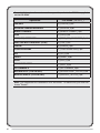
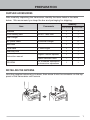
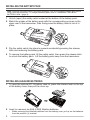
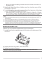
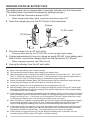
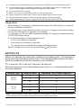
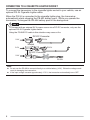
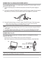
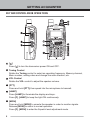
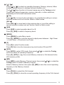
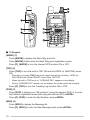
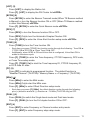
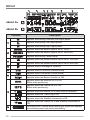
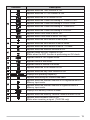
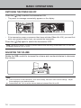
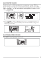
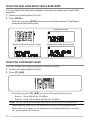
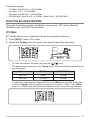
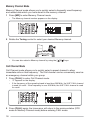
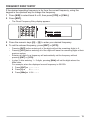
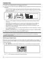
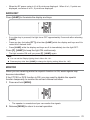
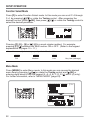
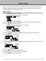
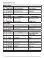
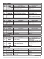
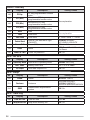
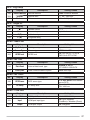
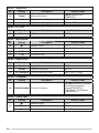
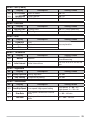
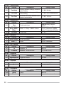
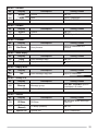
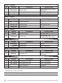
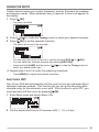
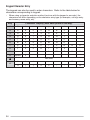
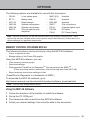
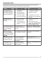
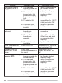
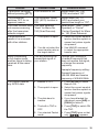
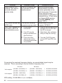
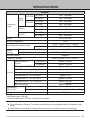
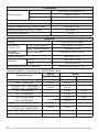


![TH-D72A TH-D72E - [::] Kenwood ASC](http://vs1.manualzilla.com/store/data/006270806_1-4dc3de1ae141fc10b999e73ed81977d3-150x150.png)