1
STEREO MINIDISC RECORDER
DMF-9020
MD-2070
INSTRUCTION MANUAL
This instruction manual is used to describe multiple models listed above.
Model availability and features (functions) may differ depending on the country and sales
area.
B60-4101-00 00 JA (K,P,T) MC 9808
Introduction
Caution : Read this section carefully to ensure safe operation.
DMF-9020/MD-2070 (En)
2
Before applying power
Units are designed for operation as follows.
U.S.A. and Canada ................................................................................................................................................................ AC 120 V only
U.K. ........................................................................................................................................................................................... AC 230 V only
For the United Kingdom
Factory fitted moulded mains plug
1. The mains plug contains a fuse. For replacement, use only a 13- Amp ASTA-approved (BS1362) fuse.
2. The fuse cover must be refitted when replacing the fuse in the moulded plug.
3. Do not cut off the mains plug from this equipment. If the plug fitted is not suitable for the power points in your home or the cable is too short to
reach a power point, then obtain an appropriate safety approved extension lead or adapter, or consult your dealer.If nonetheless the mains plug
is cut off, remove the fuse and dispose of the plug immediately, to avoid a possible shock hazard by inadvertent connection to the mains supply.
IMPORTANT :
The wires in the mains lead are coloured in accordance with the following code :
Blue: Neutral
Brown : Live
Do not connect those leads to the earth terminal of a three - pin plug.
Safety precautions
WARNING : TO PREVENT FIRE OR ELECTRIC SHOCK, DO NOT EXPOSE THIS
APPLIANCE TO RAIN OR MOISTURE.
CAUTION
RISK OF ELECTRIC SHOCK
DO NOT OPEN
CAUTION: TO REDUCE THE RISK OF ELECTRIC SHOCK, DO NOT REMOVE COVER (OR BACK). NO
USER-SERVICEABLE PARTS INSIDE, REFER SERVICING TO QUALIFIED SERVICE PERSONNEL.
THE LIGHTNING FLASH WITH ARROWHEAD SYMBOL, WITHIN AN EQUILATERAL TRIANGLE, IS INTENDED TO ALERT
THE USER TO THE PRESENCE OF UNINSULATED “DANGEROUS VOLTAGE” WITHIN THE PRODUCT’S ENCLOSURE
THAT MAY BE OF SUFFICIENT MAGNITUDE TO CONSTITUTE A RISK OF ELECTRIC SHOCK TO PERSONS.
THE EXCLAMATION POINT WITHIN AN EQUILATERAL TRIANGLE IS INTENDED TO ALERT THE USER TO THE PRESENCE
OF IMPORTANT OPERATING AND MAINTENANCE (SERVICING) INSTRUCTIONS IN THE LITERATURE ACCOMPANYING
THE APPLIANCE.
The marking of products using lasers
(Except for some areas)
CLASS 1
LASER PRODUCT
The marking is located on the rear panel and says that the component
uses laser beams that have been classified as Class 1. It means that
the unit is utilizing laser beams that are of a weaker class. There is no
danger of hazardous radiation outside the unit.
REQUIREMENT BY NEDERLAND GAZETTE
Batteries are supplied with this product. When
they empty, you should not throw away. Instead,
hand them in as small chemical waste.
Introduction
DMF-9020/MD-2070 (En)
Contents
Caution : Read the pages marked
carefully to ensure safe operation.
3
Introduction .......................................................................................................................................... 2
Before applying power ..................................................................................................................... 2
Safety precautions ............................................................................................................................ 2
Contents ........................................................................................................................................... 3
Accessories ...................................................................................................................................... 4
Special feature .................................................................................................................................. 5
IMPORTANT SAFEGUARDS ............................................................................................................... 6
Information that you should know .................................................................................................... 8
Safety Precautions ............................................................................................................................ 8
Maintenance ..................................................................................................................................... 9
System connections .......................................................................................................................... 10
Names and functions of parts .......................................................................................................... 12
Display/Main unit ............................................................................................................................ 12
Remote control unit ........................................................................................................................ 14
Operation of remote control unit..................................................................................................... 15
Playback of Mini Disc ........................................................................................................................ 16
Playing tracks in order from track No. 1 ......................................................................................... 16
Searching a desired track by its title (TITLE SEARCH) ................................................................... 17
Playback from desired track ........................................................................................................... 18
Random playback ........................................................................................................................... 18
Programming ..................................................................................................................................... 20
Programming tracks in a desired order .......................................................................................... 20
Repeated playback ......................................................................................................................... 22
Recording-related keys ..................................................................................................................... 23
AUTO/MANU. key .......................................................................................................................... 23
MONITOR key ................................................................................................................................ 23
REC MODE key .............................................................................................................................. 23
Automatically starting recording when the track starts (SOUND SYNCHRO REC) ....................... 25
Automatically pausing recording when the track ends (REC AUTO PAUSE) ................................. 25
Starting recording from the sound before the current sound (MEMORY REC) ............................ 25
Recording (ANALOG input) .............................................................................................................. 26
ANALOG recording ......................................................................................................................... 26
Recording (DIGITAL input) ................................................................................................................ 28
DIGITAL recording .......................................................................................................................... 28
Synchro recording with CD playback .............................................................................................. 30
DIGITAL recording and SCMS ........................................................................................................ 30
Editing ................................................................................................................................................. 31
Selecting the editing function type ................................................................................................. 31
Moving the track being played (TRACK MOVE) ............................................................................. 32
Moving several tracks at a time (QUICK MOVE) ............................................................................ 34
Dividing the track being played (TRACK DIVIDE) ........................................................................... 36
Combining the track being played (TRACK COMBINE) ................................................................. 38
Erasing the track being played (TRACK ERASE) ............................................................................ 40
Erasing one or more track at a time (QUICK ERASE) .................................................................... 42
Editing titles .................................................................................................................................... 44
CD text display and copy .................................................................................................................. 48
Changing the displayed contents .................................................................................................... 49
TIME DISPLAY key ......................................................................................................................... 49
METER key ..................................................................................................................................... 49
Timer operations ............................................................................................................................... 50
Timer playback, timer recording ..................................................................................................... 50
In case of difficulty ............................................................................................................................ 51
Specifications ..................................................................................................................................... 54
Introduction
DMF-9020/MD-2070 (En)
Unpacking
4
Unpack the unit carefully and make sure that all accessories are put aside so they will not be lost.
Examine the unit for any possibility of shipping damage. If your unit is damaged or fails to operate, notify your dealer immediately. If your unit was shipped
to you directly, notify the shipping company without delay. Only the consignee (the person or company receiving the unit) can file a claim against the
carrier for shipping damage.
We recommend that you retain the original carton and packing materials for use should you transport or ship the unit in the future.
Keep this manual handy for future reference.
Accessories
Check that the following accessories are present.
Audio cord (2)
System control cord (1)
Remote control unit (1)
RC-M0905
Batteries (2) (For remote control unit)
R03 ("AAA"-size) batteries
Optical fiber cable (1)
Introduction
DMF-9020/MD-2070 (En)
5
Special feature
This unit is audio equipment based on the Mini Disc format. The Mini Disc (MD) is an application of the optical and magneto-optical technology and
has the capability to record signals on discs.The operability of the MD is equivalent to the Compact Disc (CD). The MD uses optional non-contact
system so the recordings are not degraded by eternal factors and the discs are never scratched or damaged in playback.
“24 bit Rec & Play D.R.I.V.E.II” for
high-quality recording and playback
Sampling rate converter
This unit incorporates the KENWOOD-original “24-bit REC D.R.I.V.E.II”
system to allow high-quality 24-bit recording of CD as well as analog
sources such as a tuner and analog disk turntable.
The playback circuitry incorporate the KENWOOD-original “24-bit D/
A converter” for high-quality playback.
(D.R.I.V.E.:Dynamic Resolution Intensive Vector Enhancement)
The sampling rate converter incorporated in this unit is compatible
with all digital sources (32 kHz, 44.1 kHz, 48 kHz).
÷48 kHz : Standard mode of DAT. For recording of B mode broadcasting of BS
tuner, etc.
÷44.1 kHz: Standard mode of DAT. For recording of CD, MD, etc.
÷32 kHz : Standard mode and long-hour mode of DAT. For recording of A mode
broadcasting of BS tuner.
Versatile editing functions
SOUND SYNCHRO REC functions
DIGITAL REC control
Title input, title search
In addition to the conventional editing functions (MOVE, DIVIDE,
COMBINE and ERASE), this unit provides more versatile editing
functions such as the QUICK MOVE function for moving desired tracks
at once or the QUICK ERASE function for erasing desired tracks at
once.
This unit is equipped with the “SOUND SYNCHRO REC” and “AUTO
CUT” functions for automatically starting and pausing recording
simultaneously with the sound input, the “REC AUTO PAUSE” function for automatically stopping recording when the end of one track
on the CD is reached, and the “MEMORY REC” function for starting
recording from approximately 6 seconds before the current sound.
This unit is capable of adjusting the recording level during recording from a digital source as well as from an analog source. The fadein/out functions can also be used.
The “Title input” function allows to assign disc and track titles simply
using the multi-jog dial, the “Title search” function allows to find the
desired track title by checking every title, the “Title copy” function
allows to copy the CD text while recording a CD and the “Preset title”
function allows to preset frequently used titles.
IMPORTANT SAFEGUARDS
DMF-9020/MD-2070 (En)
Caution :Read this page carefully to ensure safe operation.
6
Please read all of the safety and operating instructions before
operating this appliance. Adhere to all warnings on the appliance
and in the instruction manual. Follow all the safety and operating
instructions. These safety and operating instructions should be
retained for future reference.
1. Power sources – The appliance should be connected to a
power supply only of the type described in the instruction
manual or as marked on the appliance. If you are not sure of
the type of power supply to your home, consult your appliance
dealer or local power company. For appliances intended to
operate from battery power, or other sources, refer to the
instruction manual.
2. Power-cord protection – Power-supply cords should
be routed so that they are not likely to be walked on or
pinched by items placed upon or against them, pay
particular attention to cords at plugs, convenience
receptacles, and the point where they exit from the
appliance.
6. Temperature – The appliance may not function properly
if used at extremely low, or freezing temperatures. The
ideal ambient temperature is above +5°C (41°F).
7. Heat – The appliance should be situated away from heat
sources such as radiators, heat registers, stoves, or
other appliances (including amplifiers) that produce heat.
8. Electric shock – Care should be taken so that objects do
not fall and liquid is not spilled into the enclosure
through openings. If a metal objects, such as a hair pin
or a needle, comes into contact with the inside of this
appliance, a dangerous electric shock may result. For
families with children, never permit children to put
anything, especially metal, inside this appliance.
Never pull or stretch
the cord.
9. Enclosure removal – Never remove the enclosure. If
the internal parts are touched accidentally, a serious
electric shock might occur.
3.
CAUTION
– Polarization – This appliance may be
equipped with a polarized alternating-current line plug (a plug
having one blade wider than the other). This plug will fit into the
power outlet only one way. This is a safety feature. If you are
unable to insert the plug fully into the outlet, try reversing the
plug. If the plug should still fail to fit, contact your electrician to
replace your obsolete outlet. Do not defeat the safety purpose
of the polarized plug.
4. Ventilation – Slots and openings in the cabinet are provided
for ventilation and to ensure reliable operation of the appliance
and to protect it from overheating, and these openings must
not be blocked or covered. The appliance should be situated so
that its location or position does not interfere with its proper
ventilation.
To maintain good ventilation, do not put records or a table-cloth
on the appliance. Place the appliance at least 10 cm away from
the walls.
Do not use the appliance on a bed, sofa, rug or similar surface
that may block the ventilation openings. This appliance should
not be placed in a built-in installation such as a bookcase or rack
unless proper ventilation is provided or the manufacturer’s
instructions have been adhered to.
5. Water and moisture – The appliance should not be
used near water - for example, near a bathtub, washbowl,
kitchen sink, laundry tub, in a wet basement, or near a
swimming pool, etc.
10.Magnetic fields – Keep the appliance away from sources
of magnetic fields such as TV sets, speaker systems,
radios, motorized toys or magnetized objects.
11.Cleaning – Unplug this appliance from the wall outlet
before cleaning. Do not use volatile solvents such as
alcohol, paint thinner, gasoline, or benzine, etc. to clean
the cabinet. Use a clean dry cloth.
12.Accessories – Do not place this appliance on an unstable cart,
stand, tripod, bracket, or table. The appliance may fall, causing
serious injury to a child or adult, and serious damage to the
appliance. Use only with a cart, stand, tripod, bracket, or table
recommended by the manufacturer, or sold with the appliance.
Any mounting of the appliance should follow the manufacturer’s
instructions, and should use a mounting accessory
recommended by the manufacturer. An appliance and cart
combination should be moved with care. Quick stops, excessive
force, and uneven surfaces may cause the appliance and cart
combination to overturn.
IMPORTANT SAFEGUARDS
DMF-9020/MD-2070 (En)
13.Lightning – For added protection for this appliance during a
lightning storm, or when it is left unattended and unused for
long periods of time, unplug it from the wall outlet and
disconnect the antenna or cable system. This will prevent
damage to the appliance due to lightning and power-line
surges.
18.Power lines – An outside antenna system should not be
located in the vicinity of overhead power lines or other electric
light or power circuits, or where it can fall into such power lines
or circuits. When installing an outside antenna system, extreme
care should be taken to keep from touching such power lines
or circuits as contact with them might be fatal.
14.Abnormal smell – If an abnormal smell or smoke is
detected, immediately turn the power OFF and unplug
the appliance from the wall outlet. Contact your dealer or
nearest service center.
19.AC outlets – Do not connect other audio equipment
with a power consumption larger than that specified to
the AC outlet on the rear panel. Never connect other
electrical appliances, such as an iron or toaster, to it to
prevent fire or electric shock.
POWER OFF!
15.Damage requiring service – The appliance should be
serviced by qualified service personnel when:
A. The power-supply cord or the plug has been damaged.
B. Objects have fallen, or liquid has been spilled into the
appliance.
C. The appliance has been exposed to rain or water.
D. The appliance does not appear to operate normally by
following the instruction manual. Adjust only those controls
that are covered by the instruction manual as an improper
adjustment of other controls may result in damage and will
often require extensive work by a qualified technician to
restore the appliance to its normal operation.
E. The appliance has been dropped, or the enclosure
damaged.
F. The appliance exhibits a marked change in performance.
16.Servicing – The user should not attempt to service the
appliance beyond that described in the instruction
manual. All other servicing should be referred to qualified
service personnel.
20. Overloading – Do not overload wall outlets, extension cords,
or integral convenience receptacles as this can result in a risk
of fire or electric shock.
21. Attachment – Do not use attachments not recommended by
the appliance manufacturer as they may cause hazards.
22. Replacement parts – When replacement parts are required,
be sure the service technician has used replacement parts
specified by the manufacturer or have the same characteristics
as the original parts. Unauthorized substitutions may result in
fire, electric shock, or other hazards.
23. Safety check – Upon completion of any service or repairs to
this appliance, ask the service technician to perform safety
checks to determine that the appliance is in proper operating
condition.
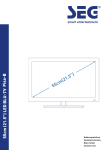
17.Outdoor antenna grounding – If an outside antenna is
connected to the appliance, be sure the antenna system
is grounded so as to provide some protection against
voltage surges and built up static charges. Article 810 of
the National Electrical Code ANSI/NFPA 70, provides
information with respect to proper grounding of the
mast and supporting structure, grounding of the lead-in
wire to an antenna discharge unit, size of grounding
conductors, location of antenna discharge unit,
connection to grounding electrodes, and requirements
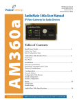
for the grounding electrode. See Figure.
EXAMPLE OF ANTENNA GROUNDING AS PER
NATIONAL ELECTRICAL CODE
ANTENNA
LEAD IN WIRE
GROUND
CLAMPS
ANTENNA
DISCHARGE UNIT
(NEC SECTION 810-20)
ELECTRIC
SERVICE
EQUIPMENT
GROUNDING CONDUCTORS
(NEC SECTION 810-21)
GROUND CLAMP
POWER SERVICE GROUNDING
ELECTRODE SYSTEM
(NEC ART 250, PART H)
NEC – NATIONAL ELECTRICAL CODE
Notes
1. Item 3 is not required except for grounded or polarized equipment.
2. Item 17 and 18 are not required except for units provided with antenna
terminals.
3. Item 17 complies with UL in the U.S.A.
7
Information that you should know
DMF-9020/MD-2070 (En)
8
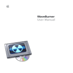
Safety Precautions
Care
Wipe periodically dust and dirt attached on the cartridge with a dry
cloth.
Write protect tab
Do not touch the disc directly.
Do not touch the disc by opening the shutter with your hand. The
cartridge will be damaged if it is forced open.
To protect recorded contents against accidental erasure, set the write
protect tab of the disc open. Return the tab to the original position
when you want to record signals on the disc.
Disc back side
Write protect tab
Storage position
Slide open.
(Recording disabled)
Do not leave Mini Discs in place where the temperature and/or
humidity are extremely high (for example, in a place subject to direct
sunlight).
Slide close.
(Recording enabled)
Note related to transportation and movement
Before transporting or moving this unit, carry out the
following operations.
1. Set the POWER key to ON without loading a Mini Disc.
÷ Check that no disc is present in the unit.
2. Wait a few seconds and verify that the display shown
appears.
ANALOG
1
PGM
SEARCH
DIGITAL
2
3
32kHz
NO
DISC
MONITOR
44.1kHz
48kHz
3. Set the POWER key to OFF.
Installation position
Dust countermeasure
The MD recorder is very sensitive to vibrations. It should be installed
in a position subject to as small vibration as possible.
The shutter of the disc cartridge is permanently open while the disc
is loaded in the set. Therefore, to prevent dust from penetrating inside
the disc, take the disc out of the unit immediately after completion of
recording or playback.
Information that you should know
DMF-9020/MD-2070 (En)
9
Maintenance
Maintenance of the set
In regard to contact cleaner
When the front panel or case becomes dirty, wipe with a soft, dry
cloth. Do not use thinner, benzine, alcohol, etc. for these agents may
cause discoloration.
Do not use contact cleaners because it could cause a malfunction. Be
specially careful not to use contact cleaners containing oil, for they
may deform the plastic component.
Unplug power cord
Reference notes
Caution on condensation
Memory backup
Condensation (of dew) may occur inside the unit when there is a great
difference in temperature between this unit and the outside.
This unit may not function properly if condensation occurs. In this
case, leave the unit for a few hours with the power left ON, and
restart the operation after the condensation has dried up.
The typical period for which the memory can be backed up while the
power cord is unplugged or the POWER key is set to the OFF position
is about 3 weeks, though this may be variable depending on the
surrounding environment.
In case of long hours of power failure or slipping out of the power cord,
the data related to recording and editing (that is usually recorded at the
moment the Mini Disc is ejected) may be cleared or destroyed before
it is written in the Mini Disc. Remember that the data lost cannot be
recovered.
After recording or editing, be sure to eject the Mini Disc so that the
recording or editing data can be written in the disc.
Be specially cautious against condensation in a following circumstance:
When this unit is carried from a place to another across a large
difference in temperature, when the humidity in the room where this
unit is installed increases, etc.
CD TEXT
CD TEXT is a system that is standardized to allow the display of text
data (disc name or song title, artist name etc.) that is recorded on CDs
in addition to music.
By digitally connecting this unit with a CD player (CD TEXT compatible),
the text data of a CD can be copied to an MD.
Presently, however, some CDs are equipped with a copy prevention
code that prohibits the copying of this data. In the case of such CDs,
copying of text data is not possible.
On CDs that do not include the text data copy prevention code, the
operation of “CD text display and copy” is possible.
i
US and foreign patents licensed from Dolby Laboratories Licensing
Corporation.
System connections
DMF-9020/MD-2070 (En)
10
Make connection as shown below. When connecting
the related system components, refer also to the instruction manuals of the related components.
Caution: Do not plug in the power lead until all connections are completed.
Malfunction of microprocessor
If operation is not possible or erroneous display appears even though all connections have been made
properly, reset the microprocessor referring to “In
case of difficulty”.
Q
Integrated amplifier
MD
SYSTEM CONTROL
REC
PLAY
ƒ
L
SL 16 XS-8
R
-
DIGITAL
OUTPUT
OPTICAL
+
-
+
R
SYSTEM CONTROL
System control
cord (CD player
optional)
ƒ
CD player
SL 16 XS-8
Audio cords ×2
(accessories)
REC
IN
1 COAX.
MD recorder
2 OPT.
3 COAX.
Optical fiber
cable ×1
(accessories)
Optical fiber cable
(optional)
L I N E
REC
PLAY
I N
OUT
REC
IN
L
L
R
R
1 COAX.
2 OPT.
System control cord ×1
(accessories)
D I G I T A L
3 COAX.
SYSTEM
CONTROL
PLAY
OUT
COAX.
OPT.
TO WALL AC
OUTLET
TEXT
DIGITAL input / output jacks
(OPTICAL)
DIGITAL
Remove protective caps
from digital input/output
jacks before use.
REC
IN
1 COAX.
2 OPT.
PLAY
OUT
3 COAX.
COAX.
OPT.
Remove cap.
÷ Be careful not to lose the protective caps.
Notes
÷ When connecting the audio cords (cords with pin plugs on each end), insert
the white plugs into the L (Left) jacks and red plugs into the R (Right) jacks.
÷ If the system components are equipped with more than one system control
cord connectors, any one of the connectors can be used.
1. Connect all cords firmly. If connections are loose, there could be loss of sound or noise produced.
2. When plugging and unplugging connection cords, be sure to first remove the power cord from the AC outlet. Plugging/unplugging
connection cords without removal of the power cord can cause malfunctions or damage to the unit.
System connections
DMF-9020/MD-2070 (En)
11
About the system control connections
About the system control connections
Connecting system control cords after connecting a Kenwood audio component system lets you take advantage of
convenient system control operations.
There are two Kenwoood system control modes. Make connections according to the groups of terminal symbols shown
below.
[XS8] Mode : lets you combine F, f, and ƒ terminals
[SL16] Mode : for [SL16] terminals only
compatible.
This unit is
You can connect this unit via system control if all other equipment using system control connections are set to the [SL16]
mode.
Notes
1. [SL16] equipment cannot be combined with [XR], [XS], and [XS8] equipment for system
operations. If your equipment consists of this kind of combination, please do not connect
any system control cords. Even without system control cords, normal operations can be
carried out without affecting performance.
2. Even if your amplifier or receiver does not have a system control terminal, the system
control functions between other components can be implemented partially by connecting
system control cords to the system control terminals of other components. (CD TEXT)
3. Do not connect system control cords to any components other than those specified by
Kenwood. It may cause a malfunction and damage your equipment.
4. Be sure the system control plugs are inserted all the way in to the system control terminals.
(See the figure at right.)
About the system control operations
Remote Control
Lets you operate this unit with the system remote supplied with the amplifier or receiver.
Automatic Operation
Automatically switches the input selector on the amplifier or receiver when you start playback from this unit.
Synchronized Recording
When recording a CD after setting the amplifier's input selector to CD, starting playback on the CD player allows to
start recording automatically in an interlocked operation.
÷ Do not operate the CD player during recording of a digital source other than CD; otherwise malfunction may occur.
÷ Synchronized recording is not possible while the SOUND SYNCHRO REC, AUTO CUT and REC AUTO PAUSE function is operating.
∞º
Note on connection of optical-fiber cable
The optical-fiber cable is designed for use in the connection
of the CD player (optional). The digital signal transmission
makes it possible to record the high-quality sound of CDs
without degradation.
÷ Insert the optical-fiber cable straight into the connector until it clicks.
÷ Be sure to attach the protection cap when the connector is not used.
÷ Never bend or bundle the optical-fiber cable.
÷ All of the commercially-available optical fiber cables cannot be used
with these units. If there is an optical fiber cable which cannot be
connected to your component, please consult your dealer or nearest
KENWOOD agent.
D.R.I.V.E.II (Dynamic Resolution Intensive Vector Enhancement) system
This unit incorporates the KENWOOD-original “24-bit REC D.R.I.V.E.II” system so that, not to mention the CD, analog sources such as the tuner and
analog disk turntable can also be recorded with high-quality 24-bit recording.
The digital inputs include both optical and coaxial input jacks so that high-quality recording is possible from any digital equipment.
1 The reproducibility of small signals is improved drastically for an excellent reproduction of fine reverberations of music. The excellence is also
remarkable in the feeling of stability, presence, attack sound and bass reproduction.
2 The D.R.I.V.E.II system maintains the correlation between the musical components of the input and output signals and does not cause any sound
degradation from the principle.
MONITOR function
This unit can be used as a 24-bit D/A converter by setting the MONITOR key.
Refer to “MONITOR key”. £
Names and functions of parts
DMF-9020/MD-2070 (En)
12
Display / Main unit
REPEAT indicator
ANALOG input indicator
PGM (Program) indicator
FADE, IN, OUT and peak level indicators
TITLE and SEARCH indicators
REPEAT
FADE
TITLE
PGM
R
SEARCH
COPY
Operation indicators
¶ REC indicator
8 Pause indicator
3 Play indicator
L
IN
SINGLE
TOTAL
REMAIN
∞
∞
MONO indicator
40
30
21
18
15
12
9
7
5
3
1
0
40
30
27
24
21
18
15
12
9
6
3
0
OVER (−dB)
OUT
OVER (−dB)
••••••••••••
SINGLE, TOTAL and
REMAIN indicators
DIGITAL input 1/2/3 indicators
ANALOG
1
3
2
MONO
MONITOR
MANUAL
A . PAUSE
Character information
display
DIGITAL
32kHz
Sumpling frequency
indicators
44.1kHz
48kHz
A. PAUSE indicator
MANUAL indicator
Display
COPY indicator
1
23 4
MONITOR indicator
6
5
78
90
REC LEVEL
STEREO MINIDISC RECORD ER
4
JOG DIAL
¢
POWER
L
REC BALANCE
R
ENTER
REC MODE
/CHARAC. /TIME DISPLAY
- O N – OFF
MIN
TITLE
SEARCH
EDIT/
SPACE
INPUT
REC INPUT
MONITOR
DISC LOADING MECHANISM
MAX
0
DOWN
UP
KEYBOARD
8
¶
7
3
PUSH SET
PHONES
LEVEL
TIMER
REC
MIN
MAX
!@ #
FADE/
DELETE
PLAY
1
24 bit Rec. & Play D.R.I.V.E.
OFF
$%^&
*
(
SEARCH
¡
) ¡™ £
¢
∞
Listening through headphones
Plug the stereo headphones (with standard-plug) available in audio
stores into the PHONES jack and adjust the listening volume with the
PHONES LEVEL control on the front panel.
LEVEL
MIN
MAX
Standby mode
While the standby indicator of the unit is lit, a small amount of current is flowing into the unit's internal circuitry to back up the
memory. This condition is referred to as the standby mode of the unit. While the unit is in the standby mode, it can be turned
ON from the remote control unit.
Names and functions of parts
DMF-9020/MD-2070 (En)
Description of main unit keys
1 POWER key
: Press to turn the unit ON and OFF.
: The unit may enter the standby mode when the POWER key
is pressed to turn it ON. This is because the unit holds the
memory that it has been put to the standby mode by the
remote control unit in the last operation.
2 Remote control sensor
: Rotate to adjust the volume of the headphones.
$ TIMER switch
: This switch is used in timer playback and timer recording.
% REC INPUT key
§•
: Press to switch the recording input line between digital
(optical/coaxial), analog and monaural.
3 EDIT/SPACE key
¤u
EDIT
: Press to switch the editing mode ON/OFF.
SPACE
: Press to insert a blank space character during the title input
operation.
4 TITLE INPUT key
r
: Press to switch the title input mode ON/OFF.
5 TITLE SEARCH key
&y
: Press to switch the title search mode ON/OFF.
: During title editing, press to switch the title change input
mode between the “overwrite mode” and “insert mode”.
6 JOG DIAL
13
# PHONES LEVEL knob
&(¤
Skip down (4)/ Skip up(¢) knob
: During playback, rotate to skip tracks.
: Before starting recording in record mode, rotate to select the
recording setting adjustment mode.
: During title search, rotate to select a track number.
: During title input, rotate to select a track number or a
character.
: During editing, rotate to select the editing mode or a track
number.
¤
PUSH SET knob
: For use in setting the editing result and input title in memory.
: When pressed in the recording pause mode, the MEMORY
REC function is set and recording starts from the sound
approximately 6 seconds before the current sound.
7 REC MODE/CHARAC. (Character) key
£t
REC MODE
: Press to switch the recording setting adjustment modes
(record modes) ON/OFF.
CHARAC.
: Press to select a character group during the title input
operation.
8 ENTER/TIME DISPLAY key
¶
: Rotate to adjust the analog recording level.
0 REC BALANCE knob
¶
: Rotate to adjust the analog recording balance.
! Keyboard connector
*r
: Connect an IBM PC compatible keyboard (optional) here.
@ PHONES jack
: Connect stereo headphones (optional) here.
£
: Press to monitor the sound being input from the source
while the unit is in stop mode.
& FADE/DELETE key
•o
FADE
: Press to switch the fade mode ON/OFF.
DELETE
: During title editing, press to delete a character. During track
editing, press to delete a track.
* Mini Disc insertion slot
: When a Mini Disc is inserted while the unit is in the standby
mode, it is turned ON automatically.
( Eject (0) key
: Press to eject the Mini Disc.
) Manual search down (1) key
(y
: This key also functions as the fast reverse key during
playback.
: During an editing mode, press to move the title input
cursor or to scroll the track title display to the left.
¡ Manual search up (¡) key
(y
: This key also functions as the fast forward key during
playback.
: During an editing mode, press to move the title input
cursor or to scroll the track title display to the right.
™ Pause (8) key
: Press to let playback or recording pause temporarily.
£ Stop (7) key
: Press to stop playback or recording.
¢ Play (3) key
: Press to start playback.
‹o
ENTER
: For use in executing the editing and title input operations.
TIME DISPLAY
: Press to switch the time and title display.
9 REC LEVEL knob
^ MONITOR key
∞ Record (¶) key
∞¶ª
: Press to start recording.
In stop mode
: When the ¶ key is pressed while a recordable disc is present
in the unit, it enters record-pause mode.
(It enters record-pause mode at the position immediately
after the last existing track.)
In record-pause mode
: When the ¶ key is pressed, the SOUND SYNCHRO REC
standby mode is set.
: In the SOUND SYNCHRO REC standby mode, the set
functions in the same way as in the normal recording pause
mode.
Names and functions of parts
DMF-9020/MD-2070 (En)
14
Remote control unit
The remote control unit incorporates the basic operation keys as well as a variety of applied operation keys so that it can be
used in a wide range of purposes.
The keys on the remote control unit with the same names as on the main unit have the same function as the keys
on the main unit.
6 CURSOR / 1 , ¡ shuttle
1 ON/STANDBY key
: Press to turn the unit between ON and
STANDBY ( / ) modes.
REMOTE CONTROL UNIT
RC-M0905
7
0
POWER
EDIT CANCEL
2 Character editing keys
TIME DISPLAY key
: Press to switch the time and title display.
CHARA. (Character)/ P.MODE (Play
Mode) key
CHARA.
: Press to select a character group during the title input operation.
P.MODE
: Press to initiate the program mode.
DELETE / CLEAR key
DELETE
: During title input, press to delete a
character.
CLEAR
: During editing, press to clear a selected
track number.
: In program mode, press to clear the
program.
SPACE / CHECK key
SPACE
: During title input, press to insert a blank
space character.
CHECK
: In program mode, press to check the
program contents.
8
9
INPUT
SEARCH
ENTER
EDIT
ABC
DEF
1
2
3
GHI
JKL
MNO
4
5
6
P.MODE
PRS
TUV
WXY
DELETE
SET
7
&( )-/
1
TITLE
8
TIME
DISPLAY
CHARA.
9
QZ
2
7 EJECT (0) key
3
8 Editing mode keys
CLEAR
’,:?!
SPACE
+100
0
+10
CHECK
MONITOR
METER
RANDOM
REPEAT
4
£
¢
÷
7
8
REC MODE AUTO/MANU. AUTO PAUSE
™™/CUR.L
REC INPUT
4
5
CUR.R/££
6
Model: RC-M0905
Infrared ray system
3 MONITOR key
: Press to monitor the sound being input
from the source while the unit is in stop
mode.
METER key
: Press to switch the level meter display
contents.
RANDOM key
: Press to initiate the random play mode.
REPEAT key
: Press to switch the repeat modes for
repeat playback.
4 Basic operation keys
3
: Play key
4 , ¢ : Skip down/up keys
¶
: Record key
7
: Stop key
8
: Pause key
CURSOR
: During title input, rotate to move the
cursor.
1,¡
: Use this during playback for forward and
reverse search.
5 Recording-related keys
REC MODE key
: Press to switch the recording setting adjustment modes ON/OFF.
AUTO/MANU. key
: Selects whether the track numbers are
to be marked automatically during recording (AUTO) or to be marked manually after it (MANUAL).
AUTO PAUSE key
: When this key is pressed, the pause
mode is initiated automatically at the
point where the track number changes
during playback.
: When pressed in the recording or recording standby mode, the AUTO REC PAUSE
mode is turned on.
REC INPUT key
: Press to switch the recording input line
between digital (optical/coaxial), analog
and monaural.
EDIT CANCEL key
: Press to cancel the editing operation.
TITLE INPUT key
: Press to switch the title input mode ON/
OFF.
TITLE SEARCH key
: Press to switch the title search mode
ON/OFF.
: During title editing, press to switch the
title change input mode between the
“overwrite mode” and “insert mode”.
SET key
: This key is used in the title assignment or
editing operations.
: When pressed in the recording pause
mode, the MEMORY REC function is set
and recording starts from the sound approximately 6 seconds before the current sound.
ENTER key
: Press to execute editing or enter the
input title in memory.
EDIT key
: Press to switch the editing mode ON/
OFF.
9 Numeric keys
0-9
: Press when selecting a track number
directly.
+10
: Press when selecting a track number 10
or more.
+100
: Press when selecting a track number
100 or more.
: These keys are also used to select a
character or symbol during title editing.
Operation of remote control unit
DMF-9020/MD-2070 (En)
Loading batteries
1 Remove the cover.
15
2 Insert batteries.
3 Close the cover.
1
2
÷ Insert two R03 ("AAA"-size) batteries following
the polarity indications.
Operation
Plug the power cord into a power outlet, then turn on the
main unit's POWER key to turn the power on. (If in the
standby mode, press the ON/STANDBY key on the remote
control unit.) Once the power has been switched ON, press
the desired operation key.
Remote sensor
÷ When pressing more than one remote control keys successively, press
the keys securely by leaving an interval of 1 second or more between
pressing of keys.
6m
30°
30°
Reference operating range
Model: RC-M0905
Infrared ray system
Notes
1. The provided batteries are intended for use in operation checking, and their service life may be short.
2. When the remote controllable distance becomes short, replace all batteries with new ones.
3. If direct sunlight or the light of a high- frequency fluorescent lamp (inverter type, etc.) is incident to the remote sensor, malfunction may
occur. In such a case, change the installation position to avoid malfunction.
Playback of Mini Disc
DMF-9020/MD-2070 (En)
16
Use the following procedure to play an MD in the original
order of tracks from track No. 1.
Before playing an MD
Set the TIMER switch to OFF.
TIMER
REC
PLAY
OFF
Disc recorded in monaural mode
This unit is capable of playing a Mini Disc recorded in the
“monaural long-play mode.” As the “monaural long-play
mode” requires half the amount of data required for
stereo mode recording, the playing time (recording time)
of the disc is doubled (to max. 148 minutes) from that in
the stereo mode.
÷ A Mini Disc recorded in the “monaural long-play mode” cannot be
played normally with equipment which is not compatible with
monaural playback.
Playing tracks in order from track No. 1
1 Turn the power ON.
ANALOG
1
PGM
SEARCH
DIGITAL
2
3
32kHz
DISC
NO
POWER
- O N – OFF
MONITOR
44.1kHz
48kHz
In case no disc is loaded:
2 Load a Mini Disc.
÷ Insert a Mini Disc into the slot securely.
÷ “READING” blinks while the unit checks the contents of the disc.
÷ If a title has been assigned to the disc, that title will be displayed.
L
PGM
SEARCH
SINGLE
In the direction of the arrow.
40
30
21
18
15
12
9
7
5
3
1
0
OVER (−dB)
ANALOG
1
R
DIGITAL
2
3
32kHz
0:00
001
MONITOR
44.1kHz
48kHz
÷ If the “PGM” indicator is lit, press the CHARA. / P.MODE key of the
remote control unit to turn it off.
3 Start playback.
÷ In a few seconds, playback starts from track No, 1.
L
7
3
PGM
SEARCH
SINGLE
∞
40
30
21
18
15
12
9
7
5
3
1
0
OVER (−dB)
ANALOG
1
R
DIGITAL
2
3
32kHz
001
Track No. being played
4:12
Elapsed time of track
being played
MONITOR
44.1kHz
48kHz
Playback of Mini Disc
DMF-9020/MD-2070 (En)
Preparation
1 Put the MD recorder in stop mode.
2 Check the track mode. (“PGM” goes
17
off)
CHARA.
P.MODE
Searching a desired track by its title (TITLE SEARCH)
1 Press the TITLE SEARCH key.
INPUT
TITLE
SEARCH
L
TITLE
PGM
∞
40
30
21
18
15
12
9
7
5
3
1
0
OVER (−dB)
ANALOG
1
R
SEARCH
DIGITAL
2
3
32kHz
TITLE
001
MONITOR
44.1kHz
48kHz
Title
Pressing the TITLE SEARCH key again cancels the
title serach mode.
÷ With a track to which no title has been assigned, the track number and
“. . . . . . . .” are displayed.
÷ Title search is possible in either stop or play mode.
2 Select the desired title.
4
JOG DIAL
¢
L
TITLE
PGM
SEARCH
∞
40
30
21
18
15
12
9
DOWN
UP
PUSH SET
To larger
track No.
5
3
1
0
OVER (−dB)
ANALOG
1
DIGITAL
2
3
32kHz
TITLE
003
To smaller
track No.
7
R
Selected track
MONITOR
44.1kHz
48kHz
Characters flow toward the left.
Pressing the TITLE SEARCH key again cancels the
title serach mode.
3 Start playback.
L
PGM
SEARCH
∞
40
30
21
15
18
12
9
5
3
1
0
OVER (−dB)
ANALOG
1
DIGITAL
2
3
32kHz
TITLE
003
7
7
R
MONITOR
44.1kHz
48kHz
3
Characters flow toward the left.
L
PGM
SEARCH
SINGLE
∞
40
30
21
18
15
12
9
7
5
3
1
0
OVER (−dB)
ANALOG
1
R
DIGITAL
2
3
32kHz
003
Track No. being played
÷ Playback starts in a few seconds.
4:12
Elapsed time of track
being played
MONITOR
44.1kHz
48kHz
Playback of Mini Disc
DMF-9020/MD-2070 (En)
18
Playback from desired track
1 Enter the track mode.
Press in stop mode.
Each press switches the mode.
1 Track mode
: PGM goes off
2 Program mode : PGM lights up
“PGM” goes off
CHARA.
L
P.MODE
PGM
SEARCH
∞
40
30
21
18
15
12
9
ABC
DEF
1
2
3
GHI
JKL
MNO
4
5
6
PRS
TUV
WXY
7
8
&( )-/
QZ
+100
0
9
’,:?!
+10
5
3
1
0
OVER (−dB)
ANALOG
1
DIGITAL
2
3
32kHz
0:00
001
2 Select the desired track number.
7
R
MONITOR
44.1kHz
48kHz
Press the numeric keys as shown below....
To enter track No. 23 : 0, 0, 3
To enter track No. 40 : 0, 0, 0, 0, )
To enter track No. 212 : +100 , +100 ,0,2
To start playback directly from a part of a track....
Early part of track No. 7 (7.2)
: 7)2
Middle part of track No. 7 (7.5) : 7)5
Latter part of track No. 7 (7.8)
: 7)8
Middle part of current track (.5) : )5
When an IBM PC compatible keyboard (optional) is connected....
To enter track No. 23
: 2, 3, Enter
To enter track No. 212
: 2, 1, 2, Enter
Middle part of track No. 7 (7.5) : 7, . , 5
÷ If a track NO. which does not exist on the disc is selected while
“READING” is blinking, the last track on the disc will be played.
Random playback
1 Enter the track mode.
Press in stop mode.
Each press switches the mode.
1 Track mode
: PGM goes off
2 Program mode : PGM lights up
“PGM” goes off
L
CHARA.
PGM
P.MODE
SEARCH
∞
40
30
21
18
15
12
9
7
5
3
1
0
OVER (−dB)
ANALOG
1
R
DIGITAL
2
3
32kHz
001
0:00
MONITOR
44.1kHz
48kHz
2 Press the RANDOM key.
RANDOM
÷ Random playback is not possible in the program mode.
÷ If the RANDOM key is pressed during random playback, random
playback is cancelled and normal playback continues from that point. (If
pressed near the end of the track, playback may skip to the beginning
of the next track.)
÷ If the RANDOM key is pressed during normal playback, playback of the
current track stops and random playback begins.
Playback of Mini Disc
DMF-9020/MD-2070 (En)
Skipping tracks
Main unit
4
Remote control unit
JOG DIAL
To skip
forward
To skip
backward
¢
4
DOWN
To skip
backward
£
¢
÷ The track in the direction of the pressed key is skipped, and the selected
track will be played from the beginning.
÷ When the 4 key is pressed once during playback, the track being
played will be played from the beginning.
÷ To return to the beginning of the previous track to the current track,
press the 4 key in less than about 2 seconds after the restart of the
current track.
UP
PUSH SET
To skip
forward
Searching in a track
Main unit
Remote control unit
Reverse
search
™™/CUR.L
Forward
search
CUR.R/££
1 SEARCH ¡
Reverse
search
Forward
search
To pause playback
Main unit
To stop playback
Remote control unit
8
÷ Playback restarts from the position with which the key is released or the
jog dial operation is terminated. (If the key was pressed in the pause
mode, the unit returns to the pause mode at that position.)
÷ Sound is output when using forward or reverse search during playback.
÷ If forward or reverse search is started during play-pause, the disc can
be searched at a high speed but sound is not output.
÷ When the reverse search is started during the program mode and the
beginning of the current track is attained, it will be played from the
)
beginning.
8
¶
Main unit
Remote control unit
7
7
3
÷ Each press pauses and plays the MD alternately.
Ejecting the disc
Main unit
Remote control unit
EJECT
NO
DISC
0
0
Mini Disc has been ejected.
AUTO PAUSE key (Remote control unit only)
When the AUTO PAUSE key is pressed, playback pauses
after every track. This function is convenient for learning a
foreign language or when time is required after each track.
AUTO PAUSE
L
PGM
SEARCH
∞
40
30
21
18
15
12
9
7
5
3
1
0
OVER (−dB)
ANALOG
1
R
DIGITAL
2
3
32kHz
002
0:00
MONITOR
44.1kHz
A . PAUSE
48kHz
“A. PAUSE” lights up
÷ Press the 3 key to resume playback.
÷ When this function is not required, be sure to press the AUTO PAUSE
key so that the “A. PAUSE” indicator is extinguished.
19
Programming
DMF-9020/MD-2070 (En)
20
Use the following procedure to program desired tracks in a
desired order. (up to 32 tracks)
Preparation
1 Load a disc.
2 Put the MD recorder in stop mode.
7
Programming tracks in a desired order
1 Initiate the program mode.
Each press switches the mode.
1 Track mode
: PGM goes off
2 Program mode : PGM lights up
CHARA.
“PGM” lights up
P.MODE
L
PGM
40
30
21
18
15
12
9
7
5
3
0
1
OVER (−dB)
ANALOG
1
R
SEARCH
DIGITAL
2
3
32kHz
TOTAL
-0:00
---
MONITOR
44.1kHz
48kHz
2 Select track numbers in the order you want to play them.
1Select the track number to be played.
ABC
DEF
1
2
3
GHI
JKL
MNO
4
5
6
PRS
TUV
WXY
7
8
&( )-/
+100
QZ
Press numeric keys in the following order.
To select track No. 12:
Press in order of 0, 2 key.
L
PGM
SEARCH
TOTAL
0
+10
30
21
18
15
12
9
7
5
3
1
0
OVER (−dB)
ANALOG
1
DIGITAL
2
3
32kHz
P-01
012
Selected track
9
’,:?!
40
R
MONITOR
44.1kHz
48kHz
Programmed order
÷ Up to 32 tracks can be selected. “FULL” is displayed when no more
track can be programmed.
÷ If you made a mistake, press the DELETE / CLEAR key and enter the
track No. again.
÷ An extremely shot track cannot be programmed.
÷ “– ✱✱ : ✱✱” is displayed when the total programmed period has
attained 256 minutes or more.
2Set the input track number.
CHARA.
P.MODE
Repeat steps 1 and 2 till the desired tracks have
been programmed, in the desired order.
÷ The input operation is aborted if the CHARA. / P.MODE key is not
pressed while the indicator is blinking.
3 Start playback.
L
PGM
£
SEARCH
TOTAL
40
30
21
18
15
12
9
7
5
3
1
0
OVER (−dB)
ANALOG
1
R
DIGITAL
2
3
32kHz
012
-30:20
Track No. being played
MONITOR
44.1kHz
48kHz
Total remaining time of the
programmed tracks
÷ Tracks will be played in the order they are programmed.
÷ When the 4 or ¢ key is pressed during playback, tracks will be
skipped in the direction of the pressed key.
Programming
DMF-9020/MD-2070 (En)
To add a track to the program
21
Press in stop mode.
ABC
DEF
1
2
3
GHI
JKL
MNO
4
5
6
CHARA.
PRS
TUV
WXY
P.MODE
7
8
9
&( )-/
+100
QZ
0
÷ When a track No. is entered, the track will be added to the end of the
existing program.
÷ The input operation is aborted if the CHARA. / P.MODE key is not
pressed while the indicator is blinking.
’,:?!
+10
Checking the order of tracks
Track No.
L
SPACE
PGM
CHECK
SEARCH
COPY
40
30
21
18
15
12
9
7
1
3
5
OVER (−dB)
0
ANALOG
1
R
DIGITAL
2
3
32kHz
P-03
014
“PGM” blinks
MONITOR
44.1kHz
48kHz
Programmed order
÷ Each press displays the next track in the program.
To clear tracks from the program
Clearing tracks from the end
Press in stop mode.
The number of the track that has been cleared is displayed.
L
DELETE
PGM
CLEAR
SEARCH
40
30
21
18
15
12
9
7
5
3
1
0
OVER (−dB)
ANALOG
1
R
---
Clearing all tracks
Press in stop mode.
P.MODE
or
Remote control unit
2
3
32kHz
P-14
MONITOR
(Example when P-14 has been cleared)
CHARA.
DIGITAL
0
÷ The entire program is cleared.
44.1kHz
48kHz
Programming
DMF-9020/MD-2070 (En)
The programmed tracks can be played repeatedly.
22 Preparation
Put the MD recorder in stop mode.
7
Repeated playback
To repeat only the programmed tracks
1 Program the tracks to be repeated.
1 Initiate the program mode.
CHARA.
Each press switches the mode.
1 Track mode
: PGM goes off
2 Program mode : PGM lights up
“PGM” lights up
P.MODE
L
PGM
SEARCH
40
30
21
18
15
12
9
7
5
3
1
0
OVER (−dB)
ANALOG
1
R
DIGITAL
2
3
32kHz
2 Select the desired tracks in the desired order.
MONITOR
44.1kHz
48kHz
ABC
DEF
1
2
3
GHI
JKL
MNO
4
5
6
CHARA.
PRS
TUV
WXY
P.MODE
7
8
9
&( )-/
+100
QZ
0
÷ All of the programmed tracks will be repeated.
÷ In case only one track is programmed, only that track will be repeated.
’,:?!
+10
2 Repeat the procedure 2.
“REPEAT” lights up
3 Enter the repeat mode.
REPEAT
REPEAT
PGM
L
SEARCH
40
30
21
18
15
12
9
7
5
3
1
0
OVER (−dB)
ANALOG
1
R
DIGITAL
2
3
32kHz
MONITOR
44.1kHz
48kHz
4 Start playback.
To stop repeated playback
£
Press the REPEAT key again.
÷ The “REPEAT” indicator goes off and the playback following the
current mode (PROGRAM) of the MD player starts.
To repeat the entire disc
1 Enter the track mode.
CHARA.
P.MODE
2 Enter the repeat mode.
Each press switches the mode.
1 Track mode
: PGM goes off
2 Program mode : PGM lights up
“REPEAT” lights up
REPEAT
REPEAT
PGM
L
SEARCH
40
30
21
18
15
12
9
7
R
5
3
1
0
OVER (−dB)
ANALOG
1
2
3
32kHz
MONITOR
3 Start playback.
DIGITAL
44.1kHz
48kHz
£
To stop repeated playback
Press the REPEAT key again.
÷ The “REPEAT” indicator goes off and the playback following the
current mode (TRACK) of the MD player starts.
Recording-related keys
DMF-9020/MD-2070 (En)
AUTO / MANU. key
23
This key is used to select whether track numbers are to be
marked automatically during recording or they are to be
marked manually during or after recording. The track numbers can be used to locate the beginning of a track during
playback or programming tracks.
Select before starting recording.
AUTO/MANU.
(Remote control unit)
L
PGM
SEARCH
∞
40
30
21
18
15
12
9
7
5
3
1
0
OVER (−dB)
ANALOG
1
R
DIGITAL
2
3
32kHz
MONITOR
MANUAL
AUTO
If a no-sound input has lasted for the time set for the AUTO TIME function
during recording, the track number will be incremented automatically by
“1”. Usually, use this position for recording. Use this mode when
recording all of the tracks in a CD. When recording music containing a
continuous section with a very low level, for example when recording
classic music, the track number may be incremented by “1” after such
a section. In this case, cancel the track number later. It is recommended
to use the MANUAL mode when recording such a kind of music.
During digital recording of CD, the track number is incremented automatically by “1” according to the data contained in the digital information. The no-sound blank is not detected.
When the CD track number is increased during manual search of a CD,
the track number recorded on the MD may sometimes fail to be
incremented.
A no sound track may sometimes created at the moment the played CD
stops.
44.1kHz
48kHz
Extinguished in “AUTO”
mode, lit in “MANUAL” mode.
MONITOR key
MANUAL
With this setting, the MD track number is not incremented automatically
during recording. Track numbers can be marked either during editing (by
pressing the EDIT key) or after recording (by executing the TRACK DIVIDE
operation fl). Even when “MANUAL” is set, the AUTO CUT and AUTO
PAUSE functions work if the “AUTO CUT” and “REC AUTO PAUSE”
settings are turned on.
This setting is convenient when recording a CD which has been recorded in
live or which contains very low-level sound such as a classical music CD.
Press to monitor the sound being input from the source while the unit is in stop mode.
When the REC INPUT is DIGITAL, the sampling rate (48 kHz, 44.1 kHz, 32 kHz) of the input digital signal can be displayed by
pressing this key.
Press in stop mode.
Main unit
L
Remote control unit
PGM
SEARCH
∞
40
30
21
18
15
12
9
7
5
3
1
0
OVER (−dB)
ANALOG
1
R
2
3
32kHz
MONITOR
MONITOR
DIGITAL
MONITOR
44.1kHz
48kHz
“MONITOR” and “Sampling rate” litghts up
REC MODE key
The recording-related settings can be adjusted precisely by selecting the proper display modes.
Selecting the setting adjustment mode
Each press switches the mode.
1 REC MODE : off
2 REC MODE : on
1Switch the REC MODE on.
REC MODE
/CHARAC.
2Select the setting adjustment mode.
4
JOG DIAL
¢
Set the selection. (by
pressing the JOGDIAL).
4
DOWN
UP
JOG DIAL
DOWN
¢
UP
PUSH SET
PUSH SET
3Adjust the setting value.
4
JOG DIAL
¢
Set the selection. (by
pressing the JOGDIAL).
4
DOWN
UP
PUSH SET
JOG DIAL
DOWN
The modes are switched by rotating the JOG DIAL.
D. REC LEVEL?
: Digital recording level setting.
AUTO CUT?
: AUTO CUT on/off selection.
AUTO TIME?
: Setting of the time for detecting a no-sound
blank section during automatic track number
marking.
AUTO LEVEL?
: Automatic track number marking no-sound
blank detection level and SOUND SYNCHRO
REC, AUTO CUT and REC AUTO PAUSE sound
detection level setting
FADE TIME?
: Setting of the fading time in fade-in and fadeout.
REC= WRITING? : Setting of the UTOC writing after recording.
¢
UP
PUSH SET
To change another setting, press the JOG DIAL (PUSH
SET knob).(This returns to step 2 above.)
÷ Step 3 consists of adjusting the setting of the “Setting adjustment
mode” selected in step 2.
÷ The “D.REC LEVEL” and “FADE TIME” settings are not used during
analog source recording.
÷ To end the setting adjustment, press the REC MODE/CHARAC. key
again.
Recording-related keys
DMF-9020/MD-2070 (En)
24
When “D.REC LEVEL?” is displayed
Initial display
L
(Valid during digital recording)
PGM
Pressing the SET key while “D.REC LEVEL?” is displayed initiates
the initial display for the digital recording level adjustment. The
recording level of the currently selected digital input can be varied
by operating the skip up/down knob. The initial setting is “DIN[1]
✱ 0 dB”, which can be set in the level range between -⬁ and +12 dB.
The figure inside [ ] indicates the current digital input number.
When “AUTO CUT?” is displayed
∞
40
30
21
15
18
12
9
7
1
3
5
OVER (−dB)
0
ANALOG
1
R
SEARCH
DIGITAL
2
3
32kHz
DIN[1]
*
0dB
MONITOR
44.1kHz
48kHz
Adjusted value display
L
PGM
∞
40
30
18
21
15
12
9
7
1
3
5
0
OVER (−dB)
ANALOG
2
3
PGM
32kHz
DIN[1]
-
dB
MONITOR
∞
L
DIGITAL
1
R
SEARCH
SEARCH
40
30
21
18
15
12
9
7
5
48kHz
1
3
0
OVER (−dB)
ANALOG
1
R
DIGITAL
2
3
32kHz
DIN[1]
44.1kHz
12 dB
MONITOR
44.1kHz
48kHz
Initial display
L
The “AUTO CUT” function sets “SOUND SYNCHRO REC” to the
pause mode automatically when the sound falls below a certain level
during recording. If the SET key is pressed while “AUTO CUT?” is
displayed, the initial AUTO CUT mode setting display appears. Use
the skip up/down knob to select AUTO CUT ON or OFF, then press the
SET key to enter that setting. The initial setting is “AUTO CUT ✱OFF”.
When “AUTO TIME?” is displayed
PGM
∞
40
30
21
15
18
12
9
L
∞
40
30
21
OVER (−dB)
0
ANALOG
DIGITAL
2
3
32kHz
CUT*OFF
Setting display
18
15
9
7
1
3
5
0
OVER (−dB)
2
3
PGM
32kHz
CUT
ON
MONITOR
∞
L
DIGITAL
ANALOG
1
AUTO
MONITOR
44.1kHz
48kHz
During recording
12
R
SEARCH
1
3
5
1
AUTO
PGM
7
R
SEARCH
SEARCH
40
30
21
18
15
12
9
7
5
1
3
0
OVER (−dB)
ANALOG
1
R
DIGITAL
2
3
32kHz
MONITOR
44.1kHz
44.1kHz
48kHz
48kHz
Initial display
L
(This is effective except during digital recording of CD)
PGM
Pressing the SET key while “AUTO TIME?” is displayed initiates the
initial display for the no-sound blank detection time adjustment for
automatic track number marking. Use the skip up/down knob to set
the no-sound blank detection time, then press the SET key to enter
that time. The initial setting is “TIME ✱ 2.0 SEC”, which can be set in
the time range between 0.5 and 4.0 seconds set in 0.5-second steps.
∞
40
30
21
15
18
12
9
7
5
1
3
OVER (−dB)
0
ANALOG
1
R
SEARCH
DIGITAL
2
3
32kHz
* 2.0SEC
TIME
MONITOR
44.1kHz
48kHz
Adjusted value display
L
PGM
∞
40
30
21
18
15
12
9
7
1
3
5
0
OVER (−dB)
ANALOG
2
3
PGM
32kHz
TIME
0. 5SEC
MONITOR
∞
L
DIGITAL
1
R
SEARCH
SEARCH
40
30
21
18
15
12
9
48kHz
7
5
1
3
0
OVER (−dB)
ANALOG
1
R
DIGITAL
2
3
32kHz
TIME
44.1kHz
4. 0SEC
MONITOR
44.1kHz
48kHz
When “AUTO LEVEL?” is displayed
If the SET key is pressed when “AUTO LEVEL?” is displayed, the
initial AUTO LEVEL mode setting display appears. The AUTO
LEVEL mode setting sets the auto track number no-sound blank
detection level as well as the SOUND SYNCHRO REC, AUTO CUT
and REC AUTO PAUSE detection levels, all at once. Use the skip
up/down knob to set the no-sound blank detection level, then
press the SET key to enter that level. This level is set for all the
above functions.The initial setting is “LEVEL ✱0”. The level can be
set between +3 and -3.
Setting
AUTO TNO
AUTO CUT
REC AUTO PAUSE
SOUND SYNCHRO REC
-3
-2
-1
Track number increments less easily
Recording pauses less easily
Recording pauses less easily
Recording starts more easily
✱0
←→
←→
←→
←→
Initial display
∞
L
PGM
40
30
21
15
18
12
9
7
5
0
1
3
OVER (−dB)
ANALOG
1
R
SEARCH
DIGITAL
2
3
32kHz
LEVEL
*0
MONITOR
44.1kHz
48kHz
Adjusted value display
L
PGM
SEARCH
∞
40
30
21
18
15
12
9
7
3
5
0
1
OVER (−dB)
ANALOG
L
DIGITAL
1
R
2
3
PGM
32kHz
LEVEL
+3
MONITOR
SEARCH
∞
40
30
21
18
15
12
9
7
48kHz
5
1
3
0
OVER (−dB)
ANALOG
1
R
DIGITAL
2
3
32kHz
LEVEL
44.1kHz
-3
MONITOR
44.1kHz
48kHz
+1
+2
+3
Track number increments more easily
Recording pauses more easily
Recording pauses more easily
Recording starts less easily
÷ During analog recording, noise on the tape, etc., may activate the SOUND SYNCHRO REC function, causing recording to start. If this happens,
raise the setting level.
AUTO TNO (Automatic track number) : Track number increments automatically
When “FADE TIME?” is displayed
Initial display
(Valid during digital recording)
L
Pressing the SET key while “FADE TIME?” is displayed initiates
the initial display for the fade time adjustment. The time period of
fade-in and fade-out operations can be varied by operating the
skip up/down knob. The initial setting is “FADE ✱ 3SEC”, which
can be set in the time range between 1 and 10 seconds in 1-second
steps.
Setting range
PGM
∞
40
21
15
18
12
9
7
5
1
3
OVER (−dB)
0
ANALOG
1
DIGITAL
2
3
32kHz
FADE
*
3SEC
MONITOR
44.1kHz
48kHz
Adjusted value display
L
PGM
∞
40
30
21
18
15
12
9
7
3
5
1
0
OVER (−dB)
ANALOG
L
DIGITAL
1
R
SEARCH
2
3
PGM
32kHz
FADE
Fade-out
30
R
SEARCH
1SEC
MONITOR
SEARCH
∞
40
30
21
18
48kHz
15
12
9
7
5
3
1
0
OVER (−dB)
ANALOG
1
R
DIGITAL
2
3
32kHz
FADE
44.1kHz
1 0SEC
MONITOR
44.1kHz
48kHz
Fade-in
When “REC =WRITING?” is displayed
“WRITING” refers to the writing of recording-related data in the
Mini Disc. Pressing the SET key while “REC = WRITING?” is
displayed initiates the initial display for the writing mode setting.
The initial setting is “WRITING ✱ON”. Use the skip up/down knob
to select whether or not to write the UTOC when recording is
completed (ON or OFF), then press the SET key to enter that
setting.
Initial display
L
PGM
∞
40
30
21
15
18
12
9
7
L
∞
40
30
21
1
0
OVER (−dB)
ANALOG
DIGITAL
2
3
32kHz
Setting display
SEARCH
3
1
WRITING
PGM
5
R
SEARCH
18
15
12
9
7
5
3
1
0
OVER (−dB)
ANALOG
1
R
DIGITAL
2
3
32kHz
WRITING
OFF
MONITOR
44.1kHz
48kHz
*ON
MONITOR
44.1kHz
48kHz
Recording-related keys
DMF-9020/MD-2070 (En)
Recording can be started or paused simultaneously with the
sound and from the sound approximately 6 seconds before
the current sound.
25
Preparation
Set the recording pause mode.
¶ª
Automatically starting recording when the track starts (SOUND SYNCHRO REC)
Recording starts when a sound above a certain level is input.
This function is particularly convenient when combined
with the AUTO CUT function to record selected tracks.
L
Press while in the recording pause mode.
PGM
SEARCH
∞
40
30
21
18
15
12
9
When the track starts, recording starts.
5
3
1
0
OVER (−dB)
ANALOG
1
DIGITAL
2
3
32kHz
SYNC.
SOUND
÷
7
R
MONITOR
44.1kHz
48kHz
÷ The sound detection level can be adjusted with the REC MODE “AUTO
LEVEL” setting.
¢
÷ When the ¶ key is pressed again, the normal recording pause mode is
set.
÷ For some music sources, the beginning of the track may be cut off.
Automatically pausing recording when the track ends (REC AUTO PAUSE)
Recording is automatically paused when the sound input is
below a certain level for over 3 seconds or when the track
number changes during digital recording of a CD.
This function comes in handy when you only want to record
one track from the CD.
Press while in the recording or recording pause
mode.
AUTO PAUSE
L
PGM
SEARCH
R
∞
40
30
21
18
15
12
9
7
5
3
1
0
OVER (−dB)
ANALOG
1
DIGITAL
2
3
32kHz
MONITOR
44.1kHz
A . PAUSE
48kHz
“A. PAUSE” lights up
÷ The sound detection level can be adjusted with the REC MODE “AUTO
LEVEL” setting.
¢
÷ Press the 7 key or the AUTO PAUSE key again to cancel the REC AUTO
PAUSE mode.
Starting recording from the sound before the current sound (MEMORY REC)
Recording starts from the sound 6 seconds before the point
at which the key is pressed.
Use this for example when recording radio programs.
Press while in the recording pause mode.
SET
Recording starts from the sound 6 seconds before the current sound.
÷ It is not possible to start recording from the sound 6 seconds before the
current sound if less than 6 seconds have passed in the recording pause
mode.
÷ When the fade mode is ON, the fade mode is switched OFF before
recording starts.
Recording (ANALOG input)
DMF-9020/MD-2070 (En)
26
The input jacks connected with audio cords accept analog signals. This unit records the analog signal from the REC IN jacks by
converting it into digital signal. (This recording is simply referred to as analog recording.)
Preparation
1 Open the write protect tab of the Mini Disc to make it recordable.
2 Load the Mini Disc.
3 Check the remaining recording time.
4 Set the amplifier’s input selector to the source to be recorded.
8
o
ANALOG recording
1 Adjust the settings if required.
1Switch the REC MODE on.
REC MODE
/CHARAC.
Each press switches the mode.
1 REC MODE : off
2 REC MODE : on
2Select the setting adjustment mode.
JOG DIAL
4
¢
DOWN
UP
PUSH SET
The modes are switched by rotating the JOG DIAL.
D. REC LEVEL?
: Digital recording level setting.
AUTO CUT?
: AUTO CUT on/off selection.
AUTO TIME?
: Setting of the time for detecting a no-sound
blank section during automatic track number
marking.
AUTO LEVEL?
: Automatic track number marking no-sound
blank detection level and SOUND SYNCHRO
REC, AUTO CUT and REC AUTO PAUSE sound
detection level setting
FADE TIME?
: Setting of the fading time in fade-in and fadeout.
REC= WRITING? : Setting of the UTOC writing after recording.
÷ For details on the setting adjustment modes, see “REC MODE key”.
£
3Set the selection (by pressing the JOG DIAL).
4
JOG DIAL
¢
÷ The “D.REC LEVEL” and “FADE TIME” settings are not used during
analog source recording.
DOWN
UP
PUSH SET
Go to step 2 if setting adjustments are not required.
2 Select ANALOG or MONO.
REC INPUT
Each press switches the mode.
1 ANALOG : Analog “stereo mode”
2 DIGITAL 1 : Coaxial input mode
3 DIGITAL 2 : Optical input mode
4 DIGITAL 3 : Coaxial input mode
5 MONO
: Analog “monaural long-play mode”
“ANALOG” lights up
L
PGM
SEARCH
∞
40
30
21
18
15
12
R
9
7
5
3
1
0
OVER (−dB)
ANALOG
1
DIGITAL
2
3
32kHz
ANALOG
MONITOR
44.1kHz
48kHz
÷ MONO cannot be selected during recording pause.
÷ The REC INPUT cannot be changed during pause in the MONO mode.
÷ The analog “monaural long-play mode”allows to double the recording
time compared to recording in the stereo mode.
Recording (ANALOG input)
DMF-9020/MD-2070 (En)
3 Select “AUTO” or “MANUAL”. (Remote control unit only)
Each press switches the mode.
1 goes off (AUTO) : Track numbers are marked automatically.
£
2 MANUAL
AUTO/MANU.
: Track numbers can be marked as desired.
£
L
PGM
∞
40
30
21
18
15
12
9
7
5
3
1
0
OVER (−dB)
1
R
SEARCH
DIGITAL
2
3
32kHz
001
4
ANALOG
MONITOR
MANUAL
44.1kHz
48kHz
Extinguished in “AUTO” mode, lit in “MANUAL” mode.
Adjust the recording level. (Main unit only)
1 Play the source to be recorded.
2 Press the ¶ key.
8
÷ The unit enters record-pause mode automatically when the ¶ key is
pressed.
¶
3 Adjust the recording level and balance.
Recording level
(inner knob)
REC LEVEL
L
MIN
To decrease
level
Recording balance
(outer knob)
REC BALANCE
REC LEVEL
REC BALANCE
L
R
MAX
MIN
To increase
level
To attenuate
the R CH
R
MAX
To attenuate
the L CH
5 Start recording.
1 Press the 8 key.
8
÷ Decrease the level if the red segments of the peak level meter light.
¶
2 Play the source to be recorded from the beginning.
Recording is not possible if the following characters are displayed.
“DISC FULL”
: Disc is full
‚w
\Erase undesired tracks.
“PROTECTED”
: The accidental erasure protect tab is open.
\Close it.
8
“PLAY ONLY”
: A playback-only Mini Disc is loaded.
\Load a recordable Mini Disc.
÷ When the EDIT / SPACE key is pressed during recording, a track
number is inserted in that position.
6 After recording, eject the Mini Disc.
WRITING
0
Information is
being written.
EJECT
NO
DISC
Mini Disc has been ejected.
÷ The eject (0)key is not accepted during recording.
Note
While “WRITING” is displayed, do not apply shock
or vibration to the unit because information is
being written on the Mini Disc.
27
Recording (DIGITAL input)
DMF-9020/MD-2070 (En)
28
Recording is possible using recordable Mini Discs. When this unit is connected with a component equipped with digital output,
such as a CD player, through a digital cord or optical fiber cable, the signal input through the DIGITAL input jack can be recorded
in the digital format (this recording is referred to as digital recording). Enjoy high-quality sound of digital recording!
Preparation
1 Open the write protect tab of the Mini Disc to make it recordable.
2 Load the Mini Disc.
3 Check the remaining recording time.
4 Set the amplifier’s input selector to the source to be recorded.
8
o
DIGITAL recording
1 Adjust the settings if required.
1Switch the REC MODE on.
REC MODE
/CHARAC.
2Select the setting adjustment mode.
JOG DIAL
4
¢
DOWN
UP
PUSH SET
3Set the selection (by pressing the JOG DIAL).
4
JOG DIAL
¢
Each press switches the mode.
1 REC MODE : off
2 REC MODE : on
The modes are switched by rotating the JOG DIAL.
D. REC LEVEL?
: Digital recording level setting.
AUTO CUT?
: AUTO CUT on/off selection.
AUTO TIME?
: Setting of the time for detecting a no-sound
blank section during automatic track number
marking.
AUTO LEVEL?
: Automatic track number marking no-sound
blank detection level and SOUND SYNCHRO
REC, AUTO CUT and REC AUTO PAUSE sound
detection level setting
FADE TIME?
: Setting of the fading time in fade-in and fadeout.
REC= WRITING? : Setting of the UTOC writing after recording.
÷ For details on the setting adjustment modes, see “REC MODE key”.
£
DOWN
UP
PUSH SET
Go to step 2 if setting adjustments are not required.
2 Select one of “DIGITAL 1, 2 and 3 ”.
REC INPUT
3 To fade in and fade out the music.
Press in stop mode.
FADE/
DELETE
Each press switches the mode.
1 ANALOG : Analog “stereo mode”
2 DIGITAL 1 : Coaxial input mode
3 DIGITAL 2 : Optical input mode
4 DIGITAL 3 : Coaxial input mode
5 MONO
: Analog “monaural long-play mode”
Each press switches the mode.
1 FADE not lit : Fade mode is off
2 FADE lit
: Fade mode is on
÷ For details on fade-in and fade-out, see “When FADE TIME? is
displayed” (¢) and “Faded recording of MD” (º).
4 Select AUTO or MANUAL. (Remotecontrol unit only)
AUTO/MANU.
Each press switches the mode.
1 goes off (AUTO) : Track numbers are marked automatically.
£
2 MANUAL
: Track numbers can be marked as desired.
£
Recording (DIGITAL input)
DMF-9020/MD-2070 (En)
5 Adjust the digital source recording level.
29
1 Play the source to be recorded.
2 Press the ¶ key.
8
÷ The unit enters record-pause mode automatically when the ¶ key is
pressed.
¶
3 Adjust the recording level.
Set the REC MODE key to ON, select the “D.REC
LEVEL?” setting adjustment display and vary the setting using the JOG DIAL.
6 Start recording.
÷ Decrease the level if the red segments of the peak level meter light.
Recording is not possible if the following characters are displayed.
“DISC FULL”
8
¶
“UNLOCK”
“SCMS ON”
“NotAudio”
“PROTECTED”
“PLAY ONLY”
: Disc is full
\ Erase undesired tracks.
‚w
: The digital cord or optical fiber cable is not locked
in position or connected incompletely (or not
connected).
\ Connect the digital cord or optical fiber cable
properly.
0
: Digital recording is inhibited by SCMS.
\ Use analog recording.
§
: The digital signal being input is not an audio
signal.
\ Use analog recording.
§
: The accidental erasure protect tab is open.
8
\ Close it.
: The disc in use is a playback-only Mini Disc.
\ Use a recordable Mini Disc.
÷ When the EDIT / SPACE key is pressed during recording, a track
number is inserted in that position.
÷ When recording is restarted after record-pause, the track number is
incremented automatically by “1”.
7 Play the source to be recorded.
8 After recording, eject the Mini Disc.
÷ To play a track with a margin from the beginning, it is recommended to
start playing the source after the time display of the MD recorder has
started the count.
WRITING
0
Information is
being written.
EJECT
NO
DISC
Mini Disc has been ejected.
÷ The eject (0) key is not accepted during recording.
While “WRITING” is displayed, do not apply shock
or vibration to the unit because information is
Note
being written on the Mini Disc.
During recording of a CD, the track number may be incremented by “1” at the moment the CD starts to play. This is caused by a signal
contained in the digital signal component of the CD. Unnecessary track numbers can be erased by following the procedure for “Erasing the
‚
track being played (TRACK ERASE).”
Recording (DIGITAL input)
DMF-9020/MD-2070 (En)
30
Synchro recording with CD playback
By connecting this unit with a KENWOOD “
” type amplifier and CD player, which are equipped with system control jacks,
using system control cords, the recording of MD can be started in synchronism with the playback of the CD player.
1 Set the amplifier’s input selector to CD.
2 Put the CD player in pause mode.
3 Select the CD track to be recorded using the 4 or ¢
key.
4 Put the MD recorder in record-pause mode.
5 Start playback of the CD player.
÷ Synchronized recording is not possible while the SOUND SYNCHRO
REC, AUTO CUT and REC AUTO PAUSE function is operating.
DIGITAL recording and SCMS
Note that the digital recording of Mini Discs is not possible in the following cases.
Note on the sampling rate converter
Three types of digital signals are usually used according to the sampling frequencies. The sampling frequencies vary
depending on the types of digital equipment as shown below.
48 kHz
: Standard mode of DAT, B mode broadcasting of BS tuner, etc.
44.1 kHz : Standard mode of DAT, CD, MD, etc.
32 kHz
: Standard and long-hour modes of DAT, A mode broadcasting of BS tuner, etc.
In general, high-quality recording based on digital signal transmission is available only when the sampling frequency of the
source equipment matches that of the recorder equipment. However, this unit incorporates a sampling rate converter so that
it can also record digital signals sampled at 48 kHz and 32 kHz by converting their sampling frequency into the sampling
frequency of MD (44.1 kHz).
The SCMS may be activated with certain type of satellite broadcasting.
(DAT: Digital Audio Tape deck)
SCMS (Serial Copy Management System)
Copy using digital
input
Designed for copyright protection, the SCMS is a prescription that copying of digital signals as they are in the
digital form between digital audio equipment is allowable
only for one generation.
Copy using digital
input
Digital copy cannot be repeated.
Copy using analog
input
If the digital source has a copy prohibition code, “SCMS
ON” is displayed and the unit enters record-pause mode.
Copy using analog
input
Copy using analog
input
Copy using digital
input
Copy using digital
input
Faded recording of MD
The fade mode of the unit is switched on/off every time the
FADE/DELETE key is pressed. The fade mode is not activated
when the D.REC LEVEL is no more than -38 dB.
Recording with fade-in:
When recording is initiated during stop (or pause) in the fade mode,
recording starts from ATT = - ⬁, increases to the previously set
recording level and continues at this level.
Fade-in and fade-out
Fade-out : Ending of music after gradual decrease in volume.
Fade-in : Beginning of music after gradual increase in volume.
Gradual sound
decrease
Gradual sound
increase
Recording with fade-out:
When recording is stopped during recording in the fade mode, the
current recording level decreases to ATT = - ⬁ then recording stops.
If recording is continued until the end of disc, fade-out occurs automatically before the unit stops recording.
1st track
Fade-out
2nd track
Fade-in
Editing
Editing
DMF-9020/MD-2070 (En)
After recording of a commercially-available recordable Mini
Disc, the recording can be edited in various ways. Note that
it is impossible to edit a playback-only Mini Disc.
(Editing is not possible while the “PGM” indicator is lit.)
Limitation of functionality due to MD standard
Some functions are limited due to the restrictions imposed by the MD standard. Before considering the symptoms as a sign of trouble with the unit, please read
Q
“Symptoms related to MD standard”.
The MD recorder acts based on the data loaded from the
disc into the memory. As this data is written in the disc at
the moment it is ejected, be sure to eject the disc every
time after the title input or editing operation.
Selecting the editing function type
Reordering tracks by moving them
Dividing a track, combining two tracks
Moving the track being played (TRACK MOVE)
Moving several tracks at a time (QUICK MOVE)
A
B
C
¤
›
Dividing the track being played (TRACK DIVIDE)
fl
D
Combining the track being played (TRACK COMBINE)
°
C
B
A
D
Erasing desired tracks (QUICK ERASE)
Erasing one or more track at a time (QUICK ERASE)w
A
B
A
C
D
C
Erasing the track being played (TRACK ERASE)
Editing titles
A
B
C
A
B
C
E
F
~
E
F
~
‚
D
U
V
W
V
W
X
Y
Z
Y
Z
w
ALL ERASE
A
B
C
D
r
Titles can be assigned to Mini Discs and tracks can have titles, and these titles can be changed or cleared later.
31
Editing
DMF-9020/MD-2070 (En)
32
This procedure shows you how to select and move (insert) a track to the track number you desire. The surrounding tracks are
renumbered automatically.
Preparation
1 Play the track to be moved.
2 Press the EDIT/SPACE key to switch
the editing mode on.
Moving the track being played (TRACK MOVE)
1 Select “MOVE”.
1 Select “MOVE”.
JOG DIAL
4
The modes are switched by rotating the JOG DIAL.
1 DIVIDE?
: Dividing a track
2 COMBINE? : Combining tracks
3 ERASE?
: Erasing track(s)
4 MOVE?
: Moving (reordering) tracks
¢
÷ Editing is aborted if no operation has been performed for 8 seconds.
DOWN
UP
PUSH SET
L
PGM
SEARCH
∞
40
30
21
18
15
12
9
7
5
3
1
0
OVER (−dB)
ANALOG
1
R
DIGITAL
2
3
32kHz
MOVE
?
MONITOR
44.1kHz
48kHz
2 Set the selection (by pressing the JOG DIAL).
4
JOG DIAL
¢
L
PGM
DOWN
SEARCH
∞
40
30
21
18
15
9
7
5
3
1
0
OVER (−dB)
ANALOG
1
DIGITAL
2
3
32kHz
0 0 1\
UP
12
R
002?
MONITOR
44.1kHz
48kHz
PUSH SET
Track being played
2 Select the move destination.
1 Select the move destination (the new track number to be assigned to the track being played).
Example of MOVE: To move track No. 1 to track No. 7
Destination track No.
4
JOG DIAL
¢
L
PGM
SEARCH
∞
40
30
21
18
15
DOWN
UP
PUSH SET
9
7
5
3
1
0
OVER (−dB)
ANALOG
1
DIGITAL
2
3
32kHz
0 0 1\
To decrease
track No.
12
R
007?
MONITOR
44.1kHz
48kHz
Track to be moved
To increase
track No.
2 Set the selection (by pressing the JOG DIAL).
4
JOG DIAL
¢
L
PGM
SEARCH
∞
40
UP
PUSH SET
21
18
15
12
9
7
5
3
1
0
OVER (−dB)
ANALOG
1
DIGITAL
2
3
32kHz
ok
DOWN
30
R
?
MONITOR
44.1kHz
48kHz
Editing
DMF-9020/MD-2070 (En)
3 Execute the track reordering operation.
Display after execution
“EDIT NOW!” : When editing is in progress
“COMPLETE!” : When editing is completed successfully
“CAN’T EDIT” : When editing is incomplete
ENTER
/TIME DISPLAY
÷ It takes a while until the execution completes.
÷ If you execute an editing operation by mistake, the condition before
editing can be recovered by performing the “EDIT CANCEL” opera‹
tion.
4 Eject the Mini Disc.
WRITING
EJECT
Information is
being written.
0
NO
DISC
Mini Disc has been ejected.
While “WRITING” is displayed, do not apply shock
or vibration to the unit because information is
being written on the Mini Disc.
Note
Image of track moving
Track to be moved
Selected destination
Selected destination
A
B
C
D
E
F
G
When moved to a position after current position
When moved to a position
before current position
A
B
C
E
F
G
D
Inserted immediately after destination track
D
A
B
C
E
F
G
Inserted immediately before destination track
To cancel the editing results (EDIT CANCEL)
To return the Mini Disc to the condition before it was loaded
in the unit, perform the following key operations before
ejecting the disc.
After canceling, the editing operation can be restarted from
the beginning.
EDIT CANCEL
SET
ENTER
÷Note that editing cannot be canceled once the recording operation has been performed after “DISC
ERROR” has been displayed.
33
Editing
DMF-9020/MD-2070 (En)
34
Use the following procedure to change the current order of
tracks by selecting a desired order and moving the tracks
together.
Preparation
1 Put the MD recorder in stop mode.
2 Press the EDIT/SPACE key to switch
the editing mode on.
Moving several tracks at a time (QUICK MOVE)
1 Select “Q.MOVE”.
The modes are switched by rotating the JOG DIAL.
1 Q. MOVE? : Moving (reordering) tracks
2 Q.ERASE? : Erasing track(s)
1 Select “Q.MOVE”.
JOG DIAL
4
¢
÷ Editing is aborted if no operation has been performed for 8 seconds.
L
PGM
DOWN
SEARCH
∞
40
30
21
18
15
12
9
7
5
3
1
PUSH SET
JOG DIAL
DIGITAL
2
?
MONITOR
3
44.1kHz
48kHz
Title scrolling
¢
L
PGM
DOWN
ANALOG
32kHz
2 Set the selection (by pressing the JOG DIAL).
4
OVER (−dB)
1
Q.MOVE
UP
0
R
SEARCH
∞
40
30
21
18
15
12
9
7
5
3
1
0
OVER (−dB)
ANALOG
1
R
2
3
32kHz
/|0 0 1 ?
UP
PUSH SET
DIGITAL
AB
MONITOR
44.1kHz
48kHz
÷ Press the EDIT/SPACE key again to abort the editing operation.
2 Select the track numbers to be moved.
Selected track No.
1 Select a track number.
4
JOG DIAL
L
¢
PGM
SEARCH
∞
40
30
21
18
15
12
9
7
5
3
1
0
OVER (−dB)
/ |0 0 4 ? A B C
DOWN
UP
To decrease
track No.
PUSH SET
To increase
track No.
JOG DIAL
L
UP
PUSH SET
Repeat steps 1 and 2 until all tracks have been arranged in the desired order.
3 End the selection of the track numbers to be moved.
ENTER
/TIME DISPLAY
2
3
32kHz
MONITOR
44.1kHz
48kHz
Next track No.
¢
PGM
DOWN
DIGITAL
÷ Only the last selected track can be cleared by pressing the FADE/
DELETE key of the remote control unit. (To clear all of the selected
tracks, cancel editing and restart the operation from the beginning.)
÷ The orders of tracks can be confirmed by pressing the 1 key (or ¡
key) of the remote control unit.
2 Set the selection (by pressing the JOG DIAL).
4
ANALOG
1
R
SEARCH
∞
40
30
21
18
15
12
9
7
5
3
1
0
OVER (−dB)
R
0 0 4 / |0 0 5 ? A B C
Selected track No.
ANALOG
1
DIGITAL
2
3
32kHz
MONITOR
44.1kHz
48kHz
Editing
DMF-9020/MD-2070 (En)
4 Select the move destination.
1 Select the move destination track number.
L
PGM
JOG DIAL
4
35
Display when tracks are moved at the top of all tracks
∞
40
30
21
18
15
12
9
7
0
1
3
5
OVER (−dB)
ANALOG
1
R
SEARCH
2
3
32kHz
T O P /« ? / 0 0 1
¢
DIGITAL
MONITOR
44.1kHz
48kHz
Display when tracks are moved between two track Nos.
DOWN
UP
To decrease
track No.
L
To increase
track No.
PUSH SET
PGM
∞
40
30
21
18
15
12
9
7
5
3
1
0
OVER (−dB)
ANALOG
1
R
SEARCH
DIGITAL
2
3
32kHz
0 0 2 /« ? / 0 0 5
MONITOR
44.1kHz
48kHz
Display when tracks are moved at the end of all tracks
L
PGM
∞
40
30
21
18
15
12
9
7
5
3
1
0
OVER (−dB)
ANALOG
1
R
SEARCH
DIGITAL
2
3
32kHz
0 1 8 /« ? / E N D
MONITOR
44.1kHz
48kHz
2 Set the movement destination (by pressing the
JOG DIAL).
JOG DIAL
4
When set
¢
L
PGM
DOWN
∞
40
30
21
18
15
12
9
PUSH SET
5 Execute the track reordering operation.
ENTER
/TIME DISPLAY
5
3
1
0
OVER (−dB)
ANALOG
1
DIGITAL
2
3
32kHz
ok
UP
7
R
SEARCH
?
MONITOR
44.1kHz
48kHz
Display after execution
“EDIT NOW!” : When editing is in progress
“COMPLETE!”: When editing is completed successfully
“CAN’T EDIT” : When editing is incomplete
÷ It takes a while until the execution completes.
÷ Do not press the 0 or “POWER” key while “COMPLETE!” is blinking,
otherwise the track reordering may be interrupted in the middle.
÷ If you execute an editing operation by mistake, the condition before
editing can be recovered by performing the “EDIT CANCEL” opera‹
tion.
6 Eject the Mini Disc .
WRITING
Information is
being written.
0
Note
EJECT
NO
DISC
Mini Disc has been ejected.
While “WRITING” is displayed, do not apply shock
or vibration to the unit because information is
being written on the Mini Disc.
Image of track insertion
1 2 3 4 5 6 7
23 24 25 26 27 28 29
Track No.
1 2 3 6 12 26 4 5 7
6
12
26
23 24 25 27 28 29
Editing
DMF-9020/MD-2070 (En)
36
Use the following procedure to divide a track into two by inserting a track number in its middle. For example, by inserting an
additional track number before the passage you are specially fond of, it is easy to skip to there when you play the disc later.
Note that the track numbers of the tracks located after the divided track are automatically incremented.
The preview function allows to fine-adjust the track division point by playing the divided part repeatedly.
Preparation
1 Play the MD track to be divided.
2 Press the EDIT/SPACE key to switch
the editing mode on.
Limitation of functionality due to MD standard
Some functions are limited due to the restrictions imposed by the MD standard. Before considering the symptoms as a sign of trouble with the unit, please read
Q
“Symptoms related to MD standard”.
Dividing the track being played (TRACK DIVIDE)
1 Select “DIVIDE”.
1 Select “DIVIDE”.
JOG DIAL
4
¢
The modes are switched by rotating the JOG DIAL.
1 DIVIDE?
: Dividing a track
2 COMBINE? : Combining tracks
3 ERASE?
: Erasing track(s)
4 MOVE?
: Moving (reordering) tracks
÷ Editing is aborted if no operation has been performed for 8 seconds.
L
PGM
DOWN
SEARCH
∞
40
30
21
18
15
12
9
7
5
PUSH SET
1
0
OVER (−dB)
ANALOG
1
DIGITAL
2
3
32kHz
DIVIDE
UP
3
R
?
MONITOR
44.1kHz
48kHz
2 Set the selection (by pressing the JOG DIAL).
JOG DIAL
4
L
¢
PGM
SEARCH
∞
40
30
21
18
15
9
7
5
3
1
0
OVER (−dB)
ANALOG
1
DIGITAL
2
3
32kHz
004?
003
DOWN
12
R
MONITOR
44.1kHz
48kHz
UP
PUSH SET
When preview is not required, press the ENTER key
once (so that “ok?” is displayed), then go to step 3.
2 Preview the result.
1 Enter the DIVIDE mode.
4
JOG DIAL
REPEAT
TITLE
¢
PGM
P.C.
DOWN
2 Execute preview.
4
DISC
L
START
SEARCH
SINGLE
TOTAL
REMAIN
∞
40
30
21
18
15
12
9
7
5
3
1
0
OVER (−dB)
ANALOG
DIGITAL
1
R
2
32kHz
DIVIDE+
00
MONITOR
44.1kHz
48kHz
UP
PUSH SET
JOG DIAL
REPEAT
¢
TITLE
PGM
P.C.
DOWN
DISC
L
START
SEARCH
SINGLE
TOTAL
REMAIN
∞
40
30
21
18
15
12
9
7
5
3
1
0
OVER (−dB)
ANALOG
DIGITAL
1
R
2
32kHz
PREVIEW
2 SEC
MONITOR
44.1kHz
48kHz
UP
PUSH SET
3 Fine-adjust the division point.
4
JOG DIAL
¢
÷ The first 3 seconds after the division point is repeated.
÷ If preview is started at the end of a track, the preview continues till the
next track (the first track if it is started in the last track), but the part in
the next track cannot be divided by TRACK DIVIDE.
REPEAT
TITLE
PGM
P.C.
DOWN
UP
PUSH SET
DISC
L
START
SEARCH
SINGLE
TOTAL
REMAIN
JOG DIAL
40
¢
18
15
12
9
7
5
3
1
0
OVER (−dB)
ANALOG
DIGITAL
1
DIVIDE+
L
SEARCH
04
∞
40
30
21
18
15
12
9
7
5
3
MONITOR
2
44.1kHz
48kHz
1
0
OVER (−dB)
ANALOG
1
R
DIGITAL
2
3
32kHz
ok
UP
PUSH SET
21
÷ Fine adjustment is possible while monitoring the sound.
÷ The dividing point can be fine-adjusted only in the forward direction
from the point where the EDIT / SPACE key was pressed initially, in 32
steps and for about 60 ms (6/100 sec.) per step.
It is recommended to start fine adjustment from slightly before the
initial division point.
PGM
DOWN
30
32kHz
4 Establish the division point.
4
∞
R
?
MONITOR
44.1kHz
48kHz
Editing
3 Execute the track divide operation.
ENTER
/TIME DISPLAY
Up to 255 track numbers can be inserted additionally
by repeating 1 to 3 for each of them.
DMF-9020/MD-2070 (En)
Display after execution.
“EDIT NOW!” : When editing is in progress
“COMPLETE!” : When editing is completed successfully
“CAN’T EDIT” : When editing is incomplete
÷ It takes a while until the execution completes.
÷ The track is divided into two tracks.
÷ The unit enters pause mode at the second track.
÷ There is no blank space left between the two tracks.
÷ Track division may sometimes be impossible due to the limitations of
the MD standard.
÷ If you execute an editing operation by mistake, the condition before
editing can be recovered by performing the “EDIT CANCEL” opera‹
tion.
4 Eject the Mini Disc.
WRITING
EJECT
Information is
being written.
0
NO
DISC
Mini Disc has been ejected.
While “WRITING” is displayed, do not apply shock
or vibration to the unit because information is
Note
being written on the Mini Disc.
Image of track division
Image of preview
Should be approx.
2 sec. or longer.
The point where the EDIT / SPACE key is pressed
1
2
3
A
1
B
2
A
3
C
4
B
Divided track (first half)
2
A
C
Divided track (second half)
1
3
B
C
Approx. 2 sec.
Fine adjustment range in 32 steps
37
Editing
DMF-9020/MD-2070 (En)
38
Use the following procedure to combine two tracks into one by deleting a track number. This operation allows to connect
several tracks or a piece of music divided into several parts. After this operation, the track numbers of tracks located after the
combined tracks are decreased automatically.
Preparation
1 Play one of the MD tracks to be
combined.
2 Press the EDIT/SPACE key to switch
the editing mode on.
Limitation of functionality due to MD standard
Some functions are limited due to the restrictions imposed by the MD standard. Before considering the symptoms as a sign of trouble with the unit, please read
Q
“Symptoms related to MD standard”.
Combining the track being played (TRACK COMBINE)
1 Select “COMBINE”.
The modes are switched by rotating the JOG DIAL.
When pressed in play mode:
1 DIVIDE?
: Dividing a track
2 COMBINE? : Combining tracks
3 ERASE?
: Erasing track(s)
4 MOVE?
: Moving (reordering) tracks
1 Select “COMBINE”.
JOG DIAL
4
¢
DOWN
÷ Editing is aborted if no operation has been performed for 8 seconds.
UP
PUSH SET
L
PGM
SEARCH
∞
40
30
21
18
15
12
9
7
5
L
¢
PGM
SEARCH
OVER (−dB)
ANALOG
∞
40
30
21
18
15
12
9
7
?
5
3
MONITOR
DIGITAL
2
3
44.1kHz
48kHz
1
0
OVER (−dB)
ANALOG
1
R
DIGITAL
2
3
32kHz
006?
005+
DOWN
0
32kHz
2 Set the selection (by pressing the JOG DIAL).
JOG DIAL
1
1
COMBINE
4
3
R
MONITOR
44.1kHz
48kHz
UP
PUSH SET
Track being played
Next track
To combine the track with the next track to it, go to step
3.
÷ To combine two tracks during playback, press the EDIT/SPACE key
while the first track is being played. (The track being played and the
track immediately after it will be combined.)
÷ If the operation is started during playback, it pauses automatically.
2 Select the track to be combined.
To combine track Nos. 5 and 7 :
4
JOG DIAL
¢
L
PGM
SEARCH
∞
40
30
21
18
15
DOWN
UP
PUSH SET
9
7
5
3
1
0
OVER (−dB)
ANALOG
1
DIGITAL
2
3
32kHz
007?
005+
To decrease
track No.
12
R
MONITOR
44.1kHz
48kHz
To increase
track No.
3 Set the selection.
L
4
JOG DIAL
¢
PGM
SEARCH
∞
40
UP
PUSH SET
21
18
15
12
9
7
5
3
1
0
OVER (−dB)
ANALOG
1
DIGITAL
2
3
32kHz
ok
DOWN
30
R
?
MONITOR
44.1kHz
48kHz
Editing
DMF-9020/MD-2070 (En)
4 Execute the track combine operation.
Display after execution
“EDIT NOW!” : When editing is in progress
“COMPLETE!” : When editing is completed successfully
“CAN’T EDIT” : When editing is incomplete
ENTER
/TIME DISPLAY
÷ It takes a while until the execution completes.
÷ If editing has been started during playback, playback restarts automatically from the current track.
÷ Track combining may sometimes be impossible due to the limitations
of the MD standard.
÷ If you execute an editing operation by mistake, the condition before
editing can be recovered by performing the “EDIT CANCEL” opera‹
tion.
5 Eject the Mini Disc.
WRITING
Information is
being written.
0
EJECT
NO
DISC
Mini Disc has been ejected.
While “WRITING” is displayed, do not apply shock
or vibration to the unit because information is
Note
being written on the Mini Disc.
Image of track combination
Should be approx.
2 sec. or longer.
1
2
A
1
3
B
2
A
4
C
D
Track No. is adjusted.
3
B
D
Track No. and title of the second track are cleared.
Track No. and title of the first track are left.
39
Editing
DMF-9020/MD-2070 (En)
40
Use the following procedure to erase a single track being
played.
Be careful in using this operation because a track may not be
recovered once it has been erased.
Preparation
1 Play the MD track you wish to erase.
2 Press the EDIT/SPACE key to switch
the editing mode on.
Erasing the track being played (TRACK ERASE)
1 Select “ERASE”.
1 Select “ERASE”.
4
JOG DIAL
¢
The modes are switched by rotating the JOG DIAL.
1 DIVIDE?
: Dividing a track
2 COMBINE? : Combining tracks
3 ERASE?
: Erasing track(s)
4 MOVE?
: Moving (reordering) tracks
÷ Editing is aborted if no operation has been performed for 8 seconds.
DOWN
UP
L
PUSH SET
PGM
SEARCH
∞
40
30
18
21
15
12
9
7
5
OVER (−dB)
ANALOG
DIGITAL
?
MONITOR
2
3
44.1kHz
48kHz
Track No. to be erased
¢
L
PGM
DOWN
0
32kHz
2 Set the selection (by pressing the JOG DIAL).
JOG DIAL
1
1
ERASE
4
3
R
SEARCH
∞
40
30
21
18
15
12
9
7
5
3
1
0
OVER (−dB)
ANALOG
1
R
PUSH SET
2
3
32kHz
-| 0 0 3
UP
DIGITAL
?
MONITOR
44.1kHz
48kHz
2 Confirm that the track has been erased.
4
JOG DIAL
¢
L
PGM
SEARCH
∞
40
21
18
15
12
9
7
5
3
1
0
OVER (−dB)
ANALOG
1
DIGITAL
2
3
32kHz
ok
DOWN
30
R
?
MONITOR
44.1kHz
48kHz
UP
PUSH SET
Confirm that the track has been erased.
3 Execute the track erasure operation.
ENTER
/TIME DISPLAY
Display after execution
“EDIT NOW!” : When editing is in progress
“COMPLETE!” : When editing is completed successfully
“CAN’T EDIT” : When editing is incomplete
÷ It takes a while until the execution completes.
÷ The track being played is erased (together with its track title).
÷ If you execute an editing operation by mistake, the condition before
editing can be recovered by performing the “EDIT CANCEL” opera‹
tion.
Editing
DMF-9020/MD-2070 (En)
4 Eject the Mini Disc.
41
WRITING
0
Information is
being written.
Note
EJECT
While “WRITING” is displayed, do not apply shock
or vibration to the unit because information is
being written on the Mini Disc.
Track to be erased
2
A
1
3
B
2
A
4
C
D
Track Nos. are adjusted.
3
B
D
DISC
Mini Disc has been ejected.
Image of track erasure
1
NO
Editing
DMF-9020/MD-2070 (En)
42
Use the following procedure to erase desired tracks in stop
mode.
Be careful in using this operation because tracks may not be
recovered once they have been erased.
Preparation
1 Put the MD recorder in stop mode.
2 Press the EDIT/SPACE key to switch
the editing mode on.
Erasing one or more track at a time (QUICK ERASE)
1 Select “Q.ERASE”.
1 Select “Q.ERASE”.
JOG DIAL
4
¢
The modes are switched by rotating the JOG DIAL.
1 Q. MOVE? : Moving (reordering) tracks
2 Q.ERASE? : Erasing track(s)
L
PGM
SEARCH
∞
40
30
21
18
15
12
9
7
5
3
1
OVER (−dB)
ANALOG
1
DIGITAL
2
3
32kHz
Q.ERASE
DOWN
0
R
?
MONITOR
44.1kHz
48kHz
UP
PUSH SET
2 Set the selection (by pressing the JOG DIAL).
4
JOG DIAL
Confirmation of all track erasure
¢
L
PGM
DOWN
SEARCH
∞
40
30
18
21
15
12
9
7
5
3
1
0
OVER (−dB)
ANALOG
1
R
2
3
32kHz
-| A L L ?
UP
PUSH SET
DIGITAL
÷÷
MONITOR
44.1kHz
48kHz
If you want to clear all tracks in a MD, go to step 3.
2 To erase desired tracks.
Selected track
1 Select a track number to be erased.
JOG DIAL
4
¢
L
PGM
SEARCH
∞
40
30
21
18
15
12
9
7
5
3
1
0
OVER (−dB)
ANALOG
1
R
-|0 0 5 ? A B C
DIGITAL
2
3
32kHz
MONITOR
44.1kHz
48kHz
Title scrolling
DOWN
UP
PUSH SET
÷ Only the last selected track can be cleared by pressing the FADE/
DELETE key of the remote control unit. (To clear all of the selected
tracks, cancel editing and restart the operation from the beginning.)
÷ The orders of tracks can be confirmed by pressing the 1 key (or ¡
key) of the remote control unit.
2 Set the selection.
4
JOG DIAL
¢
L
PGM
DOWN
UP
SEARCH
∞
40
30
21
18
15
12
9
7
5
0 0 5 -|0 0 6 ?
Selected track
1
0
OVER (−dB)
ANALOG
1
PUSH SET
Erase desired tracks by repeating steps 1 and 2.
3
R
Next track
DIGITAL
2
3
32kHz
MONITOR
44.1kHz
48kHz
Editing
DMF-9020/MD-2070 (En)
3 End the selection of the tracks to be erased.
43
ENTER
/TIME DISPLAY
L
PGM
∞
40
30
21
18
15
12
9
7
5
ENTER
/TIME DISPLAY
1
0
OVER (−dB)
ANALOG
1
DIGITAL
2
3
32kHz
ok
4 Execute the track erasure operation.
3
R
SEARCH
?
MONITOR
44.1kHz
48kHz
Display after execution
“EDIT NOW!” : When editing is in progress
“COMPLETE!” : When editing is completed successfully
“CAN’T EDIT” : When editing is incomplete
÷ It takes a while until the execution completes.
÷ If you execute an editing operation by mistake, the condition before
editing can be recovered by performing the “EDIT CANCEL” opera‹
tion.
5 Eject the Mini Disc.
WRITING
EJECT
Information is
being written.
0
DISC
NO
Mini Disc has been ejected.
While “WRITING” is displayed, do not apply shock
or vibration to the unit because information is
Note
being written on the Mini Disc.
Image of track deleting (QUICK ERASE)
Erasing all tracks:
1
2
3
Erasing desired tracks:
4
A
A
B
C
B
C
D
E
F
E
F
D
A
C
When “DISC ERROR” is displayed
If “DISC ERROR” is displayed with a Mini Disc which has
been known to be normal, re-load the Mini Disc before
proceeding to the ALL ERASE operation. This may makes it
possible to read the Mini Disc contents.
L
PGM
SEARCH
∞
40
30
21
18
15
12
9
7
5
3
1
0
OVER (−dB)
ANALOG
1
R
DIGITAL
2
3
32kHz
DISC
ERROR
MONITOR
44.1kHz
48kHz
÷ Once the “DISC ERROR” message has been displayed, the “ALL
ERASE” operation is possible but “EDIT CANCEL” operation is not
possible.
Editing
DMF-9020/MD-2070 (En)
44
When titles are assigned to a disc and its tracks, the titles
cannot only be displayed during playback but title search
(searching a track by the title) is also made possible. The
assigned titles can be changed or deleted with the same
procedure.
Preparation
1 Put the MD recorder to stop, play or
record mode.
2 Press the TITLE INPUT key to switch
the title input mode on.
About preset titles
Easy title editing is possible by memorizing titles that you
often use or titles that you like at the optional preset titles.
Changing preset title names to new ones and inputing
those titles to the mini disc is carried out with the
“Editing titles” operation.
Initial settings are as follows.
PRE1: Pops, PRE2:Rock, PRE3:Classic, PRE4:Jazz, PRE5:Disco,
PRE6:Best Hits, PRE7:Air Check, PRE8:No., PRE9:Vol.
÷ To return a changed preset title to the initial setting, please refer to
Q
“Operation to reset”.
Editing titles
1 Select the item to be edited.
Main unit
Remote control unit
1 Select whether the disc title or track title is
input.
JOG DIAL
4
¢
To return
To advance
The modes are switched by rotating the JOG DIAL.
1 DISC
: Disc title
2 001
: Track title
3 PRE 1-PRE 9 : Preset title
4 ALL ERASE? : Erasing both disc and track titles
5 CDtext LOAD? : Preparing for CD text copy (during stop)
÷ “CDtext LOAD?” is displayed only when a KENWOOD CD player with
the CD text compatibility is connected to this unit.
÷ Editing is aborted if no operation has been performed for 8 seconds.
To edit a disc title: Select “DISC”.
L
4
DOWN
£
¢
TITLE
PGM
SEARCH
∞
40
30
21
18
15
12
9
7
5
3
1
0
OVER (−dB)
ANALOG
1
R
DIGITAL
2
3
32kHz
DISC
ABCDE
MONITOR
44.1kHz
48kHz
UP
To edit a track title: Select the desired track number.
PUSH SET
To return
To advance
L
TITLE
PGM
SEARCH
Press the JOG DIAL.
JOG DIAL
30
21
18
15
12
9
7
5
3
1
0
OVER (−dB)
ANALOG
1
DIGITAL
2
3
32kHz
-----
MONITOR
44.1kHz
48kHz
To edit the preset titles: Select the desired preset number.
¢
L
TITLE
SET
DOWN
40
003
2 Set the selection.
4
∞
R
PGM
SEARCH
∞
40
30
21
18
15
12
9
7
5
3
1
0
OVER (−dB)
ANALOG
1
R
DIGITAL
2
3
32kHz
PRE4
Jazz
MONITOR
44.1kHz
48kHz
UP
PUSH SET
To abort operation, press the TITLE INPUT key again.
To erase both disc and track titles.
L
TITLE
PGM
To input a title, go to step 2.
To change or delete a title, go to step 3.
SEARCH
∞
40
30
21
18
15
12
9
7
5
3
1
0
OVER (−dB)
ANALOG
1
R
DIGITAL
2
3
32kHz
ALL
ERASE?
MONITOR
44.1kHz
48kHz
Characters usable in title editing
The following alphabets and symbols (ASCII codes) can be
selected for use in title editing. Titles can also be input by
connecting an IBM PC compatible keyboard (optional) to the
keyboard connector on the front panel.
Uppercase alphabets x 26
Lowercase alphabets x 26
Numerals x 10
Space & symbols x 26
:
:
:
:
ABCD...WXYZ
abcd...wxyz
0123456789
!"#$%&'()✱+,-./:;<=>`?@^_
In addition to the entry of above characters, the keyboard
can also control the following functions.
Keyboard key Control/editing function
F1
TITLE INPUT
F2
TITLE COPY (Copying displayed title data
into PRE 9)
F3
TITLE PASTE (Copying title data from PRE 9)
F4
SET
F5
EDIT/SPACE
F6
RANDOM
F7
TITLE SEARCH
F8
F9
F10
F11
F12
BACK SPACE
REC MODE/CHARAC.
PLAY
PAUSE
REC
STOP
Deleting the character before the cursor
during title input
SHIFT+CAPS LOCK Switching the uppercase/lowercase letters during title input
ENTER
ENTER
SPACE
Entering a blank space during title input
INSERT
Switching overwriting/insertion during
title input
DELETE
Deleting the character indicated by the
cursor during title input
↑
SKIP UP
↓
SKIP DOWN
→
FF
←
FB
Editing
DMF-9020/MD-2070 (En)
2 Input the title.
Main unit
45
Remote control unit
1 Select a character group.
One of the following character groups can be selected.
• A to Z and space (a blank character):
• a to z and space:
• 0 to 9, symbols, preset titles (x 9):
REC MODE
/CHARAC.
CHARA.
P.MODE
2 Select a character.
JOG DIAL
4
¢
ABC
DEF
1
2
3
GHI
JKL
MNO
4
5
6
PRS
TUV
WXY
7
8
9
&( )-/
+100
DOWN
QZ
0
The characters can be switched by rotating the JOG DIAL.
• A to Z and space (a blank character):
¤ A
£
¤ D
¤ E
¤ F
¤ E E E E E
¤
¤ b
¤ c
¤ d
¤ e
¤ f
¤ E E E E E
¤
+10
• 0 to 9, symbols, preset titles (x 9):
¤ 0
PRE9
To advance
4
¤ a
’,:?!
PUSH SET
To return
¤ C
• a to z and space:
or
UP
¤ B
¤ 1 ¤ E E E ¤ 9 ¤
' E E E ' PRE1 ' _
¤ ! ¤ h E E E
' ^
' @ ' ?
¢
Example of new title input:
Initial display
Total number of title characters
Up to 1792 characters can be input per disc and up to 80
characters can be input per track. (In case of alphanumeric
and symbol characters)
A space (blank character) also required the same amount
of data as alphanumeric characters. When deleting a title,
it is not recommended to overwrite spaces on previous
characters but use the DELETE function.
L
TITLE
PGM
SEARCH
∞
40
30
21
18
15
12
9
L
TITLE
SEARCH
5
3
1
0
OVER (−dB)
ANALOG
1
∞
40
30
21
18
15
DIGITAL
2
3
32kHz
|
PGM
7
R
ABC
12
9
7
5
3
MONITOR
44.1kHz
48kHz
1
0
OVER (−dB)
ANALOG
1
R
DIGITAL
2
3
32kHz
|J K L M
MONITOR
44.1kHz
48kHz
Selected character
÷ The display can be scrolled so that any character (in a single group) can
be selected.
÷ Characters can also be selected directly from the remote control unit by
using the numeric keys.
(Example: Each press of the 2 key switches characters in order of
A = B = C.)
÷ The cursor can be moved to the left and right with the 1 and ¡ keys.
÷ Pressing the TITLE SEARCH key during title input switches the input
mode between the “overwrite mode” and “insert mode”.
3 Set the selected character.
Press the JOG DIAL.
L
4
JOG DIAL
¢
TITLE
SET
DOWN
PGM
SEARCH
∞
40
30
21
18
15
12
9
7
5
3
K
1
0
OVER (−dB)
ANALOG
1
R
|J K L M
UP
This procedure is continued on next page.
2
3
32kHz
MONITOR
PUSH SET
Repeat steps 1 to 3 till all of the title characters have been
input.
DIGITAL
÷ Pressing the EDIT/SPACE key inserts a blank space character.
44.1kHz
48kHz
Editing
46
DMF-9020/MD-2070 (En)
3 To change or erase a title.
Main unit
Remote control unit
1 Move the character to the desired character
PGM
40
30
18
21
15
12
9
7
1
3
5
OVER (−dB)
ANALOG
DIGITAL
1
2
3
32kHz
K E N E O O D|
™™/CUR.L
0
R
SEARCH
(to be changed).
To return
∞
L
TITLE
ABC
MONITOR
44.1kHz
48kHz
CUR.R/££
To advance
Selected character blinks.
1 SEARCH ¡
÷ If the title to be changed is too long to be displayed on the display
section, press the 1 or ¡ key to scroll the display so that the
characters hidden until then appear.
÷ Press the FADE/DELETE key to erase the selected character.
To advance
To return
2 Select a character group.
REC MODE
/CHARAC.
One of the following character groups can be selected.
• A to Z and space (a blank character):
• a to z and space:
• 0 to 9, symbols, preset titles (x 9):
CHARA.
P.MODE
÷ The display can be scrolled so that any character (in a single group) can
be selected.
3 Select the “overwrite mode” or “insert mode”.
INPUT
TITLE
SEARCH
Each press switches the mode.
1 Overwrite mode : Inputs a character by replacing the existing
character.
2 Insert mode
: Inputs a character before or after an existing character.
Cursor types
”
Overwrite mode : Larger cursor “
TITLE
INPUT
SEARCH
”
: Smaller cursor “
Insert mode
4 Select a character.
4
JOG DIAL
¢
ABC
DEF
1
2
3
GHI
JKL
MNO
4
5
6
Selecting the correct character (in overwrite mode):
The cursor moves.
L
TITLE
PGM
DOWN
PRS
TUV
WXY
7
8
9
SEARCH
∞
40
30
21
18
15
12
9
7
OVER (−dB)
0
1
3
5
ANALOG
1
R
K E N E O O D|V W X Y
DIGITAL
2
3
32kHz
MONITOR
44.1kHz
48kHz
UP
&( )-/
PUSH SET
To return
To advance
+100
QZ
0
’,:?!
+10
or
4
£
¢
÷ The display can be scrolled so that any character (in a single group) can
be selected.
÷ Characters can also be selected directly from the remote control unit by
using the numeric keys.
(Example: Each press of the 2 key switches characters in order of
A = B = C.)
÷ The cursor can be moved to the left and right with the 1 and ¡ keys.
5 Set the selected character.
Press the JOG DIAL.
4
JOG DIAL
L
¢
TITLE
SET
DOWN
UP
PUSH SET
All characters of a title can be changed or erased by repeating
steps 1 to 5.
PGM
SEARCH
∞
40
30
21
18
15
12
9
7
R
5
3
1
0
OVER (−dB)
ANALOG
1
DIGITAL
2
3
32kHz
KENWOOD
MONITOR
44.1kHz
48kHz
Editing
DMF-9020/MD-2070 (En)
4 Execute title change or deletion.
47
Main unit
Remote control unit
1 Enter the title in memory.
L
ENTER
/TIME DISPLAY
TITLE
PGM
SEARCH
∞
40
30
21
15
18
9
7
5
3
1
0
OVER (−dB)
ANALOG
1
DIGITAL
2
3
32kHz
S TO RE!
DISC
ENTER
12
R
MONITOR
44.1kHz
48kHz
2 Complete the operation.
INPUT
TITLE
SEARCH
L
TITLE
INPUT
TITLE
PGM
SEARCH
SEARCH
∞
40
30
21
15
18
12
9
7
5
3
1
0
OVER (−dB)
ANALOG
1
R
DIGITAL
2
3
32kHz
K EN
MONITOR
44.1kHz
48kHz
The title is scrolled automatically.
5 Eject the Mini Disc.
Main unit
WRITING
Remote control unit
0
Information is
being written.
0
Note
EJECT
NO
DISC
Mini Disc has been ejected.
While “WRITING” is displayed, do not apply shock
or vibration to the unit because information is
being written on the Mini Disc.
Title editing function keys
REC MODE / CHARAC. key:
Press to switch the character groups on the character display.
Manual search (1, ¡) keys:
Press to move the cursor during title input operation.
(lower half only) : The input character is inserted before the character in the cursor position.
When the cursor is
When the cursor is
: The input character replaces the character in the cursor position.
FADE / DELETE key:
Press to clear (delete) the character on the cursor position and move the characters after it by one character backward. Pressing the key successively
(or holding it depressed) allows to clear a title easily.
EDIT / SPACE key:
Press to enter (insert) a space (one blank character) immediately before the character in the cursor position and move the characters after it by one
character forward. Multiple spaces can also be entered by pressing the key successively (or holding it depressed). The spaces are mainly used to leave
spaces for later addition of characters before adding characters to a title.
Scrolling the display
There may be cases in which the amount of information is too large
to be displayed at a time during the title input operation, etc. In such
a case, pressing the 1 or ¡ key repeatedly allows to move the
displayed characters to the left (or right) so that other information
which has been hidden can be displayed. This leftward or rightward
movement of the display characters is referred to as “scrolling.”
Main unit
Displayed area (All cannot be displayed.)
ABCDEFGHIJKLMNOPQRSTUVWXYZ
Scrolling \
Remote control unit
™™/CUR.L
1 SEARCH ¡
Example of scrolling
CUR.R/££
ABCDEFGHIJKLMNOPQRSTUVWXYZ
| Scrolling
ABCDEFGHIJKLMNOPQRSTUVWXYZ
CD text display and copy
DMF-9020/MD-2070 (En)
48
By connecting this unit with a KENWOOD CD Text-compatible CD player (which carries “CD TEXT” marking on the rear panel)
through a synchro cord and a digital cord or optical fiber cable, the text (disc titles and track titles) of CD tracks can be copied
onto a MD disc. It is not possible to copy the text alone. However, note that the copying of CD text may not be possible with
certain discs.
Preparation
1 Set the amplifier’s input selector to CD.
2 Switch off the program mode of the CD player.
3 Put the CD player and MD recorder to stop mode.
4 Set the MD recorder to the DIGITAL mode for accepting the input signal from the CD player.
Loading (displaying) the CD text
1 Switch the TITLE INPUT mode on.
INPUT
TITLE
SEARCH
2 Select “CDtext LOAD”.
JOG DIAL
4
Each press switches the mode.
1 TITLE not lit : TITLE INPUT mode is off
2 TITLE blinking : TITLE INPUT mode is on
The modes are switched by rotating the JOG DIAL.
1 DISC
: Disc title
2 001
: Track title
3 PRE 1-PRE 9 : Preset title
4 ALL ERASE? : Erasing both disc and track titles
5 CDtext LOAD? : Preparing for CD text copy
¢
L
TITLE
PGM
40
30
18
21
15
12
9
7
1
3
5
0
OVER (−dB)
ANALOG
DIGITAL
1
2
3
32kHz
SINGLE
DOWN
∞
R
SEARCH
L OAD?
CDte xt
MONITOR
44.1kHz
48kHz
UP
PUSH SET
L
TITLE
PGM
COPY
3 Set the selection (by pressing the JOG DIAL).
4
JOG DIAL
DOWN
¢
UP
PUSH SET
To delete the CD text data copied on MD:
While “COPY” is lit, press the REC INPUT key to switch the
mode.
Copying the CD text
1 Load CD text.
2 Record the digital signal of the CD onto a MD.
Ejecting MD after loading or copying
SEARCH
SINGLE
∞
40
30
21
18
15
12
9
7
5
3
1
0
OVER (−dB)
ANALOG
1
R
L
DIGITAL
2
3
TITLE
PGM
32kHz
COMP LETE !
“COPY” blinks
MONITOR
COPY
44.1kHz
48kHz
SEARCH
SINGLE
∞
40
30
21
18
15
12
9
7
5
3
1
0
OVER (−dB)
ANALOG
1
R
DIGITAL
2
3
32kHz
001
0 : 00
MONITOR
44.1kHz
48kHz
“COPY” lights up
÷ When the text copy function has been set, the text (track titles) is
transmitted from the CD to the MD.
÷ When the CD player is not designed to display the CD text, the CD text
corresponding to each track is displayed as the CD tracks are played
after loading.
Display after execution
“COMPLETE!”
: Copy is completed.
“CAN’T LOAD”
: Copy is incomplete.
“CAN’T ACCESS” : A CD text-compatible CD player is not connected
to this unit.
“CDtext EMPTY” : The CD in use is not a CD text disc or no CD is
loaded in the player.
“Now Analog In” : CD text cannot be loaded because the current
input mode is the analog mode.
“UNLOCK”
: CD text cannot be loaded because the digital cord
or optical fiber cable is disconnected or connected
improperly.
÷ To abort recording in the middle, press the 7 key of the CD player.
÷ To abort the CD text copy in the middle, eject the copy source CD.
Display after execution
“NO TEXT COPY” : Copy failed. (When the CD inhibits the copy operation)
WRITING
Information is
being written.
EJECT
NO
DISC
Mini Disc has been ejected.
0
While “WRITING” is displayed, do not apply shock
or vibration to the unit because information is
Note
being written on the Mini Disc.
÷ The copied CD text data is deleted automatically.
Changing the displayed contents
DMF-9020/MD-2070 (En)
TIME DISPLAY key
49
This key allows to switch the mode of time display.
Main unit
Each press switches the time display modes.
In play/stop mode
1 SINGLE(+) : Elapsed time of the track being played
2 SINGLE(–) : Remaining time on the track being played
3 TOTAL(+)
: Total elapsed play time of tracks
4 TOTAL(–)
: Total remaining play time of tracks (The total number of tracks is also displayed during stop mode.)
5 REMAIN
: Remaining recording time of disc
6 TITLE
: Track title display (during playback) or Mini Disc
title display (during stop)
In recording mode
1 SINGLE(+) : Elapsed play time of track being recorded
2 TOTAL(+)
: Total elapsed play time of tracks
3 REMAIN
: Remaining recording time of disc
When no track has been recorded
1 SINGLE(+) : “BLANK DISC” is displayed. (“NO TRACKS” is
displayed if the disc has a title.)
2 REMAIN
: Remaining recording time of disc
3 TITLE
: The Mini Disc title is displayed
Remote control unit
ENTER
/TIME DISPLAY
TIME
DISPLAY
METER key
The level meter display contents can be switched over in cycle.
1. Normal display
: The scale around 0 dB is set finely in this
mode, which is suitable for normal recording
(rock) or playback (pop music).
: The scale is set almost evenly from 0 dB to 30
dB in this mode, which is suitable for playing
music with wide level variation from pianissimo to fortissimo, such as classical music.
2. Wide display
Each press switches the level meter display modes.
1 Example of normal display:
L
PGM
SEARCH
∞
40
30
21
18
15
12
9
7
5
3
1
0
OVER (−dB)
ANALOG
1
R
DIGITAL
2
3
32kHz
SINGLE
MONITOR
44.1kHz
48kHz
2 Example of wide display:
Remote control unit
L
PGM
METER
SEARCH
R
∞
∞
40
30
21
18
15
12
9
7
5
3
1
0
OVER (−dB)
40
30
27
24
21
18
15
12
9
6
3
0
OVER (−dB)
SINGLE
ANALOG
1
DIGITAL
2
3
32kHz
MONITOR
44.1kHz
48kHz
FADE key
Level meter display during fade-in/fade-out
By switching the fade mode on, each track can be recorded with
gradual sound increase at the beginning and gradual sound decrease at the ending.
The fade mode can be switched on when the unit is ON, the REC
INPUT is DIGITAL, in stop mode or in record mode. Press the FADE/
DELETE key again to switch the fade mode off.
The fade mode is not activated when the D.REC LEVEL is no more
than -38 dB.
Upper row of level meter : The level information during fade-in
and fade-out is displayed graphically.
Lower row of level meter : The meter segments light according to
the current R + L CH level.
Example (During FADE IN):
The indicated level increases (toward the right) as fade-in advances.
FADE
Mainunit
FADE/
DELETE
L
IN
PGM
SEARCH
SINGLE
R
∞
∞
40
30
21
18
15
12
9
7
5
3
1
0
OVER (−dB)
40
30
27
24
21
18
15
12
9
6
3
0
OVER (−dB)
4:12
008
ANALOG
1
DIGITAL
2
3
32kHz
MONITOR
44.1kHz
48kHz
Example (During FADE OUT):
“FADE” light up
FADE
PGM
SEARCH
L
R
∞
The indicated level decreases (toward the left) as fade-out advances.
40
30
21
18
15
12
9
7
5
3
1
0
OVER (−dB)
ANALOG
1
DIGITAL
2
MONITOR
FADE
3
32kHz
44.1kHz
48kHz
L
IN
PGM
SEARCH
SINGLE
R
∞
∞
40
30
21
18
15
12
9
7
5
3
1
0
40
30
27
24
21
18
15
12
9
6
3
0
015
2:02
OVER (−dB)
OUT
OVER (−dB)
ANALOG
1
DIGITAL
2
3
32kHz
MONITOR
44.1kHz
48kHz
Timer operations
Amplifier
50
DMF-9020/MD-2070 (En)
Playback or recording can also be activated at the desired
time by using a commercially available timer.
PHONES
Connect the power cords of the associated components so
that their power can be turned ON through the audio timer.
Also, be sure to read carefully the instruction manual of the
timer.
Do not set timer recording in a way that the power is not turned
ON for more than 3 days; otherwise, the last recorded data
may be cleared.
Audio cord
Audio cord
Tuner
Refer to “Memory backup”. 9
Audio timer
DMF-9020/MD-2070
Timer playback, timer recording
1 Turn the powers of the associated components ON.
÷ Set the POWER key of the unit to ON.
2 Make preparations.
For timer playback
For timer recording
Load a prerecorded Mini 1 Load a recordable Mini
Disc.
Disc.
2 Receive the desired radio
station.
3 Select the desired mode
with the REC INPUT key.
§
4 Adjust the recording level.
÷ For timer recording, be sure to set the write protect tab to enable
8
recording.
÷ For timer recording, be sure to check the remaining recording time.
o
3 Set the amplifier volume.
For timer playback
For timer recording
1 Play the Mini Disc.
2 Adjust the amplifier vol-
Minimize the amplifier volume.
ume.
3 Stop the disc.
4 Set the TIMER.
For timer playback
For timer recording
TIMER
REC
TIMER
PLAY
OFF
REC
PLAY
OFF
÷ When the set time comes, the disc playback or recording starts
automatically. (Also be sure to read the instruction manual of the
connected component carefully.)
5 Set the timer ON time.
For timer playback
For timer recording
Set the timer so that it supplies power at the specified
time.
Set the timer so that the
tuner reception can be
started at the desired time
of the day.
÷ After having set the timer, be careful not to press the ON/STANDBY
key of the remote control unit to ON; otherwise the timer operation
would be activated.
In case of difficulty
DMF-9020/MD-2070 (En)
What appears to be a malfunction may not always be serious. If your unit should not perform as expected, consult the table
below to see if the problem can be corrected before seeking help from your dealer or service representative.
Operation to reset
The microprocessor may fall into malfunction (impossibility to operate
erroneous display, etc.) when the power cord is unplugged while power
is ON or due to an external factor. In this case, execute the following
procedure to reset the microprocessor and return it to normal condition.
With the POWER key left to ON, unplug the power cord
from the power outlet then, while holding the eject (0)
key depressed, plug the power cord again.
÷ Please note that resetting the microprocessor clears the contents
stored in, it returns the microprocessor to the condition when it left
the factory.
Symptoms related to MD standard
Symptom
Cause
“DISC FULL” is displayed while the disc still has a remaining recordable time.
÷ More than 255 tracks (track No. 256 or more) cannot be recorded. (There
may be also cases in which recording is impossible while the track
number is less than 256.)
In such a case, the REMAIN time display shows “0:00”.
The recordable time does not increase after a short track has been
erased.
÷ The remaining time display becomes “0:00” when the actual total
remaining time of the Mini Disc is less than 12 seconds. The recordable
time display changes when the total time of the erased track exceeds
12 seconds.
÷ When a Mini Disc has been subjected to repeated editing, the remaining
time may not increase even after a short track has been erased.
Tracks cannot be combined.
÷ A track created as a result of an editing operation may sometimes be
impossible to be combined with another track.
The total of the recorded time and recordable time does not coincide
with the total recording time of the MD (60 or 74 min.).
÷ As recording is performed on a minimum recording basis of 2 seconds,
the displayed time may not coincide with the consumed disc capacity.
Sound is interrupted when a track created by editing is subjected to
fast forward or fast backward operation.
÷ Sound interruption may occur due to a combination of various factors,
and it is not a malfunction.
Tracks are not numbered correctly.
÷ A short track may be created depending on the contents of the recorded
source (CD, for example).
The period in which “READING” is displayed is abnormally long.
÷ “READING” is displayed for a longer period than usual when a brandnew recordable Mini Disc (a virgin disc) is loaded.
÷ The Mini Disc in use has been processed with repeated editing or
contains a large number of tracks.
The total number of characters used in the titles is less than 1792
characters.
÷ As the title recording areas are used on a per-7-character basis, the total
number of input characters may be less than 1792.
51
In case of difficulty
DMF-9020/MD-2070 (En)
Displayed messages and actions to be taken against them
52
Displayed Message
Meaning
Action
NO DISC
÷ This unit is not loaded with disc.
÷ Load a disc.
UNLOCK
÷ The digital cord or optical fiber cable is not
locked in position or connected incompletely (or
not connected).
÷ The digital cord or optical fiber cable is not
locked in position or connected incompletely (or
not connected).
0
SCMS ON
÷ An attempt is made to record digital signal from
a source while its digital copy has been prohibited by SCMS.
÷ Use analog recording.
§
NotAudio
÷ The digital signal being input is not an audio
signal.
÷ Use analog recording.
§
DISC FULL
÷ There is no recordable area on the disc.
÷ An attempt is made to record a 256th track.
÷ Use another recordable disc.
÷ More than 255 tracks cannot be recorded per
disc.
TITLE FULL
÷ An attempt is made to assign a title with more
characters than usable.
÷ Refer to ”Total number of title characters”.
BLANK DISC
÷ The disc does not contain any recordings.
÷ When playback is required, use a recorded disc.
NO TRACKS
÷ The disc does not contain any tracks but has a
disc title.
÷ The disc can be used for recording without any
problem.
READING
÷ The TOC*1 data of the disc is being read.
÷ This is a normal operation.
WRITING
÷ The data related to editing or recording is being
written in the disc.
÷ This is a normal operation.
DISC ERROR
÷ The contents of UTOC*2 are abnormal.
÷ Erase all tracks by executing ”_+ALL”. If this is
not possible, use another Mini Disc.
w
EDIT NOW!
÷ The editing operation is in progress.
÷ This is a normal operation.
CAN’T EDIT
÷ An attempt is made to perform editing beyond
the restrictions, for example to erase a track
which is too short.
÷ Perform editing following the restrictions.
ok? (blinking)
÷ This is a message for confirming if editing can
really be executed.
÷ Press the ENTER key to execute editing.
PROTECTED
÷ The Mini Disc is in the “WRITE PROTECT”
condition.
÷ Release the “WRITE PROTECT” condition.
PLAY ONLY
÷ A playback-only Mini Disc is loaded.
÷ Load a recordable Mini Disc.
CAN’T ACCESS
÷ A CD text-compatible CD player is not connected to this unit.
÷ Connect the unit with a KENWOOD CD textcompatible CD player using the synchro cord
0
and optical cable.
CAN’T LOAD
÷ The disc loaded in the CD player is not CD textcompatible.
÷ The CD player is not connected to this unit
through an optical cable.
÷ Load a CD text-compatible disc in the CD player.
÷ The CD player is in play mode or in the program
mode.
t
8
÷ Connect the CD player through an optical cable
and set the REC INPUT of the MD recorder
0
accordingly.
÷ Switch the program mode of the CD player off
and put both the CD player and MD recorder in
stop mode.
CDtext EMPTY
÷ The CD in use is not a CD text disc.
÷ No CD is loaded in the player.
÷ Use a CD containing CD text.
÷ Use a CD containing CD text.
Now Analog In
÷ The current input mode is the analog mode.
÷ Set the REC INPUT to the digital input to which
•
the CD player is connected.
NO TEXT COPY
÷ The CD text of certain discs cannot be copied.
÷ The CD text of the current disc cannot be
copied. (Use a copy-capable CD disc.)
In case of difficulty
DMF-9020/MD-2070 (En)
Other symptoms
Symptom
Sound is not output even when the play
key is pressed.
Cause
÷ The cords are connected erroneously.
÷ No disc has been loaded.
÷ A non-recorded disc has been loaded.
53
Remedy
÷ Connect the cords in accordance with “System
connections”.
0
÷ Load a disc.
÷ Load a prerecorded disc or playback-only disc.
÷ The disc is write-protected.
÷ Change the position of the write protect tab to
the write position or use a recordable disc.
÷ An attempt is made to record digital signal from
a source while its digital copy has been prohibited by SCMS.
÷ The recording level is too low (in case of analog
recording).
÷ A playback-only disc has been loaded.
÷ The disc does not have a recordable area.
÷ The REC INPUT key is not set to the actual input
source.
÷ If the amplifier is connected to this unit through
a system control cord, the amplifier’s input
selector is set to the MD input.
÷ Use analog recording.
8
§
÷ Adjust the recording level again.
¶
Sound is distorted.
÷ The recording level has not been adjusted.
÷ A disc in which distorted sound has been recorded is played.
÷ Adjust the recording level.
÷ Use another disc.
Noise is noticeable.
÷ An external noise is induced.
÷ Install the unit at a position apart from an electric appliance or TV set.
Power cannot be turned on from the remote control.
÷ The POWER key is set to OFF.
÷ Set the POWER key to on (STANDBY).
Keyboard operation is not available.
÷ The keyboard is connected improperly.
÷ Connect the keyboard properly.
Recording is not possible
÷ Use a recordable disc.
÷ Use another disc.
÷ Set it according to the actual input source.
§•
÷ Set the amplifier’s input selector to other position than MD.
¶
TOC*1 : All minidiscs contain a Table of Contents (TOC) in addition to sound signals. The TOC is similar to the table of contents in a book and
W
contains information, such as track numbers, track length, and character information, that cannot be rewritten.
UTOC*2 : In addition to the TOC, minidiscs also contain a special User’s Table of Contents (UTOC) that contains track number, track length, and
W
character information, that can be rewritten.
Specifications
DMF-9020/MD-2070 (En)
[Format]
54
System ....................................................................................... Minidisc digital audio system
Laser ........................................................................................... Semiconductor laser
Recording method .................................................................... Field modulation overwrite method
Audio compression ................................................................... ATRAC (Adaptive TRansform Acoustic Coding)
Playing rotation ........................................................................ Approx. 400 rpm ~ 900 rpm (CLV)
[D/A conversion]
D/A conversion ......................................................................... 1 Bit (24 bit type)
Oversampling ............................................................................ 8 fs (352.8 kHz)
[A/D converter]
A/D converter ............................................................................ 4 th order sigma-delta conversion+ D.R.I.V.E. conversion
Sampling frequency ................................................................. 44.1 kHz
[Digital audio performance]
Frequency responce (playback mode) .................................... 8 Hz ~ 20 kHz (± 1 dB)
Signal to noise ratio (playback mode) ................................... More than 112 dB
Dynamic range (playback mode) ............................................ More than 96 dB
Total harmonic distortion (1 kHz, playback mode) ............... Less than 0.004 %
Wow & flutter............................................................................ Less than unmeasurable limit
Analog input sensitivity / input impedance .......................... 500 mV / 22 kΩ
Analog output level / output impedance ............................... 2.0 V / Less than 300 Ω
Headphone output .................................................................... 50 mW/32 Ω load (Phones level MAX)
Digital input
Coxaial .................................................................................... 0.5 Vp-p / 75 Ω
Optical(Wave length 660 nm) .............................................. - 15 dBm ~ - 21 dBm
Digital output
Coxaial .................................................................................... 0.5 Vp-p / 75 Ω
Optical(Wave length 660 nm) .............................................. - 15 dBm ~ - 21 dBm
[General]
Power consumption ................................................................. 20 W
Dimensions ................................................................................ W : 440 mm (17 - 5 / 16”)
H : 125 mm ( 4 - 15 / 16”)
D : 373 mm (14 - 11 / 16”)
Weight (Net) .............................................................................. 5.4 kg (11.9 lb)
Notes
1. KENWOOD follows a policy of continuous advancements in development. For this reason specifications may be changed without notice.
2. The full performance may not be exhibited in an extremely cold location (under a water-freezing temperature).
DMF-9020/MD-2070 (En)
For the U.S.A.
FCC WARNING
This equipment may generate or use radio frequency energy. Changes or modifications to this equipment may cause harmful interference unless
the modifications are expressly approved in the instruction manual. The user could lose the authority to operate this equipment if an unauthorized
change or modification is made.
NOTE:
This equipment has been tested and found to comply with the limits for a Class B digital device, pursuant to Part 15 of the FCC Rules. These limits
are designed to provide reasonable protection against harmful interference in a residential installation. This equipment may cause harmful
interference to radio communications, if it is not installed and used in accordance with the instructions. However, there is no guarantee that
interference will not occur in a particular installation. If this equipment does cause harmful interference to radio or television reception, which can
be determined by turning the equipment off and on, the user is encouraged to try to correct the interference by one or more of the following measures:
– – Reorient or relocate the receiving antenna.
– – Increase the separation between the equipment and receiver.
– – Connect the equipment into an outlet on a circuit different from that to which the receiver is connected.
– – Consult the dealer or an experienced radio/TV technician for help.
For the U.S.A.
CAUTION :
Use of controls or adjustment or performance of procedures
other than those specified herein may result in hazardous radiation exposure.
In compliance with Federal Regulations, following are reproductions of labels on, or inside the product relating to laser product
safety.
KENWOOD CORPORATION
2967-3, ISHIKAWA-CHO, HACHIOJI-SHI,
TOKYO,JAPAN
KENWOOD CORP. CERTIFIES THIS EQUIPMENT
CONFORMS TO DHHS REGULATIONS NO. 21
CFR 1040.10, CHAPTER 1, SUBCHAPTER J.
Location: Back Panel
55
For your records
Record the serial number, found on the back of the unit, in the spaces
designated on the warranty card, and in the space provided below. Refer
to the model and serial numbers whenever you call upon your dealer for
information or service on this product.
Model
Serial Number