1
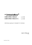
AM360a User Manual
revised 2009.05.25 for
Hardware Rev. A
Firmware Version 1.00.24
AM360a
AudioMate 360a User Manual
www.VoiceInterop.com
IP Voice Gateway for Audio Devices
Table of Contents
Quick Start Guide............................................................................... 3
Gather Your Tools
Basic Configuration Steps
AudioMate 360a Product Tour.......................................................... 5
Front Panel
Rear Panel
Installation.......................................................................................... 7
Network Considerations
Bandwidth Consumption and Codecs
Electrical Considerations
Configuration..................................................................................... 8
Network Address
Configuring by Web Browser
Global Configuration
Module Configuration
Status................................................................................................... 13
Global Status
Module Status
AudioMate 360a Specifications......................................................... 16
8000 N. Federal Highway, Suite 100, Boca Raton, FL, 33487 V: +1 561.939.3300
AM360a User Manual
revised 2009.05.25 for
Hardware Rev. A
Firmware Version 1.00.24
Appendix A - Interface Examples...................................................... 17
Public Address (Paging) Amplifier
LMR Remote Control
Weather Radio Channel
Digital I/O Connections
Appendix B - Multicast Addressing Notes........................................ 19
Limitations on Multicast Group Address Choices
Appendix C - WAVE Configuration.................................................. 20
Multicast Configuration
Unicast Configuration
This document is copyright © 2008, 2009 by VoiceInterop, Boca Raton, Florida, U.S.A.
All rights reserved.
www.VoiceInterop.com
8000 N. Federal Highway, Suite 100, Boca Raton, FL, 33487 V: +1 561.939.3300
AM360a User Manual
revised 2009.05.25 for
Hardware Rev. A
Firmware Version 1.00.24
Quick Start
Quick Start Guide
Gather Your Tools
Web browser — Mozilla Firefox, Opera, Chrome, or Internet Explorer.
AM360 Configuration
Utility
www.voiceinterop.com
Register as a customer
Choose the Support tab.
Download AudioMate 360 IP
Setup configuration utility
AM360 Configuration Utility — To find the address of each AM360 gateway, download the
AudioMate 360 IP Setup utility from our web site, www.voiceinterop.com under the Support
tab. You must first register as an owner of an AudioMate 360 gateway to be granted access.
(Optional) Telnet client — comes with Windows, or you can use a third-party client.
(Optional) USB Comm Port Driver — To view the boot and debug messages and set
passwords you will need the USB comm port driver set from FTDI. These are quite common
in many products so you might already have them installed.
(Optional) USB A to USB-mini B cable — To connect from your computer to the AM360 serial
port
(Optional) Terminal program — HyperTerminal comes with Windows, or you can use a thirdparty datacomm terminal.
NO soldering iron nor screwdriver is needed to set up the gateway, just a web browser and a
plan.
Basic Configuration Steps
¤
¤
¤
¤
¤
Find the IP address
Log in
Set the RTP address and ports
Connect the audio device
Set audio levels with a partner
Find the AudioMate 360 IP Address
Use the AM360 (AudioMate 360) Configuration Utility to find the IP address that was
assigned by your DHCP server. Click the Locate button and select a unit from the list on the
left pane.
Log In to the AudioMate Unit with a Web Browser
Type the IP address of the desired unit from the list displayed by the AM360 Configuration
Utility into the address bar of your web browser and press Enter. The AM360 will prompt you
for the user name and password. The factory values are admin and password.
Set the RTP Address and Ports
The default AM360 settings might be all that you need to get going. If necessary, set the
Remote RTP Address, RTP Remote Port, and RTP Local Port to communicate with your audio
network.
Connect the Audio Device
Connect the audio device to the AudioMate 360a, whether it be a public address amplifier to
the Line Output or a broadcast radio or an iPod to the Line Input. A microphone should be
connected via the RJ45 on the front panel.
www.VoiceInterop.com
8000 N. Federal Highway, Suite 100, Boca Raton, FL, 33487 V: +1 561.939.3300
AM360a User Manual
revised 2009.05.25 for
Hardware Rev. A
Firmware Version 1.00.24
Set Audio Levels With a Partner
Set the Microphone, Line In, or Line Out Levels as appropriate to make the speech intelligble
and pleasant to listen to. Be careful not to overdrive the AudioMate with too loud an input
signal. This test requires two people: one to talk and another to listen.
See the Configuration section for detailed instructions.
To Set the Password with Telnet
To set the username and password on the AM360 use telnet to the IP address discovered by
the AM360 Configuration Utility. The factory default username is admin and the password is
password. After logging in, type the command ‘help’ to list the available commands.
To Set the Password via USB Serial Port
USB Drivers
The USB comm port drivers
can be downloaded directly
from the FTDI web site:
ftdichip.com/FTDrivers.htm
www.VoiceInterop.com
If telnet is not available, as a last resort the USB serial port can be used after installing the
FTDI USB comm port emulators on your computer. These drivers can be downloaded from
the FTDI web site. The comm port parameters are 115200 bps, 8 data bits, no parity, 1 stop
bit. Once connected, send Ctrl-C (Control-C) to switch the unit to command mode. Type the
command ‘help’ to list the available commands.
Please note that there are no audio settings available via telnet nor serial comm port, these
must be configured via a web browser.
8000 N. Federal Highway, Suite 100, Boca Raton, FL, 33487 V: +1 561.939.3300
AM360a User Manual
revised 2009.05.25 for
Hardware Rev. A
Firmware Version 1.00.24
tour
AudioMate 360a Product Tour
Front Panel
Front Panel Indicators
All front panel indicator LEDs can display one of seven color states: OFF, RED, RED FLASHING,
GREEN, GREEN FLASHING, AMBER and AMBER FLASHING each of which can be used to
indicate a different condition within the AudioMate 360a.
LED
Amber
Amber
flashing
Green
Green
flashing
Red
Red
flashing
OK
Booting,
awaiting
DHCP
address
N/A
Normal
operation
N/A
Boot error
(view boot
via USB
serial port)
N/A
Link
N/A
Check LAN
connection
LAN
connection
OK
AMCP
data traffic
received
N/A
N/A
Rx
Buffering
audio from
IP network
N/A
Playing RTP
stream out
audio port
N/A
N/A
N/A
Tx
N/A
N/A
N/A
N/A
Sending
RTP stream
to LAN
N/A
Speaker
Maximum
volume
N/A
Mid-range
N/A
Minimum
volume
N/A
Mic.
Maximum
mic level
N/A
Mid-range
N/A
Minimum
mic level
N/A
Line out
Maximum
line level
N/A
Mid-range
N/A
Minimum
line level
N/A
Line in
Maximum
line level
N/A
Mid-range
N/A
Minimum
line level
N/A
Pressing the Volume knob will select each audio line for adjustment.
www.VoiceInterop.com
8000 N. Federal Highway, Suite 100, Boca Raton, FL, 33487 V: +1 561.939.3300
AM360a User Manual
revised 2009.05.25 for
Hardware Rev. A
Firmware Version 1.00.24
Front Panel Connections
Microphone — Accepts an 8-pin RJ-45 microphone plug on a Kenwoood KMC-27B pushto-talk mobile radio microphone. Other microphones might work and you may construct a
suitable microphone using the pin-outs listed in Appendix A.
Front Panel Controls
Volume — The Volume control serves two functions: 1) selecting which audio line to adjust,
and 2) adjusting the audio level. Select which of the four audio lines to adjust by pushing
in the Volume knob and observing the indicator lamps on the front panel. The audio line
whose indicator is illuminated will be adjusted by turning the Volume knob. There are 16
steps in the adjustment even though the Volume knob turns continuously. The lowest level
is indicated by a red lamp, the highest level is indicated by an amber lamp, while all steps
in between these extremes are indicated by a green lamp. The button presses and the level
steps are echoed on the USB serial diagnostic port. Additionally, the resulting level settings
may be observed on the unit’s internal web page management screen.
Rear Panel
Rear Panel Indicators
LAN Port — The LAN jack has two built-in lamps: a solid green one indicating that an
electrical link has been established, the other flashing green indicating packet activity.
Rear Panel Connections
Speaker — This 3.5mm mini phone jack allows connection of an 8-Ohm speaker to provide
a simple means to get audio from the network into a small space such as a desk cubicle or
small office. The audio power output is approximately 1/2 Watt. A monaural plug is preferred
or use the tip of a stereo plug leaving the sleeve open.
Line Out — This 3.5mm mini phone jack allows connection to a line-level input of a public
address amplifier, tape recorder, digital audio recorder, or other audio device. Monaural or
stereo plugs will work properly in this port.
Line In — This 3.5mm mini phone jack allows connection of a line-level audio device, such
as a CD player, iPod, tape recorder line output, AM/FM broadcast receiver, or NOAA weather
radio receiver. Monaural or stereo plugs will work properly in this port.
www.VoiceInterop.com
8000 N. Federal Highway, Suite 100, Boca Raton, FL, 33487 V: +1 561.939.3300
AM360a User Manual
revised 2009.05.25 for
Hardware Rev. A
Firmware Version 1.00.24
I/O — Digital Input and Output lines. A 5-pin inline receptacle whose mating plug uses
screw terminals to accept bare wire.
GND — Signal ground.
I/O 1 — (COR) Pull low to stream RTP audio packets to the network.
I/O 2 — (PTT) Goes low to indicate RTP packets are being received from the network.
D+ and D- — RS485 data loop; not implemented.
LAN — Standard 10/100BaseT Ethernet port with RJ-45 pin-outs following the AT&T T568B
specification. A standard Category 5 LAN cable connects it to an Ethernet switch.
USB — Allows a trained technician with a correctly setup computer to establish a direct
serial connection to the AudioMate 360 internal Diagnostic Console. Connects via a standard
USB A to Mini-B cable. The computer must have the Virtual Comm. Port driver from FTDI
(ftdichip.com) installed along with any standard terminal emulator. This port is used for
diagnostics; no voice parameters can be set.
12 V — 12 Volt d.c. input, tip is positive, ring is negative. The supplied power adapter converts
120 Volt a.c. main power to 12 Volts d.c. at 500 mA maximum. The power plug has a 1.3mm
inner diameter.
Rear Panel Controls
Reset — This recessed push button reboots the processor in the AudioMate 360. Depress
using a pen or any device with a small tip. The length of time that it is held depressed
determines the type of reset:
Quick Reset – A momentary press performs a simple reset.
Factory Reset – Press and hold until OK light goes from AMBER to GREEN to reset those
options found on the web configuration screens to factory defaults. While the AudioMate
360 is awaiting an address from a DHCP server this could take as much as 60 seconds. In
order to ensure that the device loads factory default settings the Reset button must be
held this entire time, until the OK light changes from AMBER to GREEN.
installation Installation
Network Considerations
In the typical AudioMate installation all endpoints are contained entirely in a corporate
LAN, or participate via a WAN link, either unicast through a VPN or an engineered MPLS
network, for example. It is preferable that all routers serving network segments that
connect AudioMate endpoints be configured to route multicast streams. This can smooth
implementation of multicast systems in general (such as videoconferencing), and the
deployment of AudioMate Communicator remote control soft consoles in particular.
Multicast is used to allow multiple endpoints to share one stream of audio packets, thus
reducing bandwidth consumption. However, while multicast streams typically pass
seamlessly through Ethernet switches, they are typically blocked by most routers unless
proper preparations are made to accommodate multicast. It is a near certainty that multicast
www.VoiceInterop.com
8000 N. Federal Highway, Suite 100, Boca Raton, FL, 33487 V: +1 561.939.3300
AM360a User Manual
revised 2009.05.25 for
Hardware Rev. A
Firmware Version 1.00.24
streams will not flow through most Internet routers. Therefore, unicast addresses are
acceptable for use in the AudioMate 360 line of IP gateways, although multicast is preferred..
Bandwidth Consumption and Codecs
The G.711 codec (encoder/decoder algorithm) consumes approximately 84kilobits/second
per stream. More aggressive codecs consume less bandwidth, but their output audio is
typically of lower quality. Some codecs perform poorly in environments with high acoustic
noise near the microphone. Narrowband IP links might require a more aggressive codec,
while endpoints on your LAN will likely do well with the G.711 codec. Because the AudioMate
Media Server can perform transcoding between algorithms you have the opportunity to
optimize bandwidth usage versus audio quality.
Electrical Considerations
The AudioMate 360 gateways are powered by 12 Volts d.c. which can be provided by the
supplied plug-in power supply or by a 12 Volt battery with float charging system. In either
case, the power must be clean and free of a.c. noise components and interruptions. The
supplied power module should be plugged into an uninterruptible power supply (UPS) for
trouble-free service. If a 12 Volt battery/charger system is used, the charger must keep noise
to less than 12mVp-p.
config
Configuration
Each unit requires two groups of configuration data: one group that is common across the
AudioMate 360 family and a second group that is specific to the application of the unit.
Network Address
The units are shipped with DHCP enabled and will accept whatever address is assigned
by your DHCP server. On startup the AM360 will wait up to 60 seconds for a DHCP server
to assign its IP address. On timeout the AM360 will assign itself a default IP address of
192.168.0.254 and a netmask of 255.255.255.0.
AM360 Config Utility
The Address Finder utility is
available by logging in to our
web site:
www.voiceinterop.com
Click the Support tab.
Locating the AM360 Address
Use the AudioMate 360 Configuration utility to locate the addresses of your units in
preparation for configuration. Individual AudioMate 360 units are configured via web
browser pointed to the unicast management IP address of the unit. The Address Finder
utility is available by logging in to our web site
www.voiceinterop.com
Click the Support tab to find the link to download the AM360 Configuration Utility.
Open the AM360 Configuration Utility and click the Locate button and select a unit from the
list on the left pane. The IP address of each unit is to the right of each minus sign.
Configuring by Web Browser
Type the address of the desired AM360 unit into the address bar of your web browser. (At
the time of this writing the freely available Mozilla Firefox web browser provides smoother
operation for these purposes.)
www.VoiceInterop.com
8000 N. Federal Highway, Suite 100, Boca Raton, FL, 33487 V: +1 561.939.3300
AM360a User Manual
revised 2009.05.25 for
Hardware Rev. A
Firmware Version 1.00.24
Logging In
AudioMate 360 Login
username = admin
password = password
Like most network devices, the AM360 is protected by a password. The factory default for
user name is admin and the factory default password is password.
When prompted by the web interface enter the appropriate user name and password. If they
were accepted you will see a two part screen with a menu panel on the left pane and a page
labeled AM360 Status on the right pane.
Global Configuration
In the menu pane on the left, locate the Configuration heading and click the link Global
under it. The screen labeled AM360 Configuration should appear in the right pane.
You may safely ignore the AMCP settings.
This Unit’s Name allows you to set a memorable name uniquely to identify this unit among
the others on your network. This field accepts standard alphanumeric characters.
Boot IP Addr
After changing the IP address
of the AM360r you must
reboot the unit to make the
new IP address effective.
Also remember to change
the address in your browser!
www.VoiceInterop.com
Boot IP Mode selects between automatic IP address assignment by your DHCP server or
static IP address assignment specified in the fields that follow. If you select Static IP and
then click the Update Unit button, the IP Boot fields will be filled with current values. If
you select DHCP and click the Update Unit button the fields will be returned to 0.0.0.0
which indicates DHCP. Note that editing and saving the Boot IP fields has no effect on
communications until you reboot the unit.
Boot IP Addr sets the static unicast management IP address used to configure this unit.
Default is 0.0.0.0 for DHCP. Once you change this address, set the mask, update and reboot
the unit, remember to point your web browser to the newly assigned address.
Boot IP Mask sets the netmask or network portion of the IP address. In a typical Class C
network this will be 255.255.255.0 while the default value is 0.0.0.0 for DHCP use. If you set a
static IP address you must also set this field to represent the size of your network.
8000 N. Federal Highway, Suite 100, Boca Raton, FL, 33487 V: +1 561.939.3300
AM360a User Manual
revised 2009.05.25 for
Hardware Rev. A
Firmware Version 1.00.24
Boot IP Gateway sets the default network gateway router that will carry your packets to
other networks. If you set a static IP address you must also set the gateway to the default
router on your network. The default value is 0.0.0.0 for DHCP use.
Boot IP DNS sets the IP address of your DNS server, if needed. Typically this address will be
the same as your default gateway in small networks. Default is 0.0.0.0 for DHCP use.
AMCP Configuration
You may safely ignore the AMCP settings.
RTP Configuration
RTP Remote IP
is the address of other unit
if using unicast, not the one
that you are configuring.
Multicast Addressing
Appendix B has more detail
on selecting multicast
addresses with pointers to
reference sources.
RTP Remote IP is the address to which audio packets will be sent. In multicast networks
type the multicast group which will share audio with other units on the same multicast
group. The Class D multicast range lies between 225.0.0.0 and 239.255.255.255
with numerous restrictions and considerations. Consult Appendix B for more information
on multicast address assignment. For point-to-point unicast links type the unicast address
(Boot IP Address) of the other end of the link, not this unit. A unicast address set here
should fall within your network’s private IP address space. Default is 239.1.1.1 multicast
group.
RTP Remote Port is the IP port number assigned to this channel. This should be an even
number between 16384 and 65534. Default is 18000.
RTP Local Port should be identical to the RTP Remote Port number. Default is 18000.
Codec should be set to G711u for most applications. Other choices are G711a for G.711 A-law,
and GSM for GSM 6.1 full rate. The G.711 codecs use about 84 kbits/second while the GSM
codec uses about 13 kbs/sec. Default is G.711 µ-law codec.
Save Your Changes
Update Unit button — When you are satisfied with all the settings that appear on the
Global Configuration page, be sure to click on the button labeled Update Unit at the top
of the page. Your new settings take effect immediately, except for the fields labeled IP Boot.
The IP Boot fields only take effect after a reboot.
Undo Edits button — To revert back to the previously saved values while editing click the
button labeled Undo Edits at the top of the page.
Reboot checkbox — To reboot, check the Reboot box and click the Update Unit button. Any
changes are saved before the reboot is executed.
Module Configuration
In the menu pane on the left, locate the Configuration heading and click the link Module
under it. The screen labeled AM360a (Audio) Config should appear in the right pane.
Microphone Level displays the current setting of the Microphone input level. To set this
level electronically, type in a value between 0 and 15 and click Update Unit.
Microphone Continuous Stream forces the AM360a to stream audio to the network
continuously, regardless of the PTT input from the microphone. Check this box to force
continuous streaming; clear this checkbox to require the PTT microphone digital input to
control streaming to the network.
www.VoiceInterop.com
8000 N. Federal Highway, Suite 100, Boca Raton, FL, 33487 V: +1 561.939.3300
10
AM360a User Manual
revised 2009.05.25 for
Hardware Rev. A
Firmware Version 1.00.24
Line In Level displays the current setting of the Line Input level. To set this level
electronically, type in a value between 0 and 15 and click Update Unit.
Line In Continuous Stream forces the AM360a to stream audio to the network continuously,
regardless of the state of the I/O 1 input on the rear. Check this box to force continuous
streaming; clear this checkbox to require the I/O 1 on the rear connector to control
streaming to the network.
VOX Enable provides positive control of the voice activation feature. When VOX is enabled,
any sound from the microphone or line inputs that exceeds the VOX Threshold level will
trigger the sending of packets to the IP network. Check this box to enable VOX using the
values entered in the following fields; clear this checkbox to disable VOX and require the
hardware logic inputs to trigger audio streaming.
VOX Threshold sets the audio level above which the AM360a will begin streaming audio
to the network without requiring a hardware digital signal (COS or I/O 1) to go active.
Type a number between 0 and 50 that provides the desired operation. A value of 0 is the
most sensitive setting while 50 is the least sensitive. NOTE that VOX operation will prevent
proper operation of channel patches on soft console systems.
VOX Timeout enables the VOX feature and sets the hang time during which the AM360a will
continue to stream RTP packets to the network after the audio level falls below the VOX
Threshold level. Set this to a value between 0.1 and 25.5 seconds that eliminates choppy
operation with the type of audio that you are streaming. When this value is set to 0 (zero)
the VOX feature will be disabled for backward compatibility.
Speaker Volume displays the current setting of the Speaker output level. To set this Volume
level electronically, type in a value between 0 and 15 and click Update Unit.
Line Out Level displays the current setting of the Line Output level. To set this level
electronically, type in a value between 0 and 15 and click Update Unit.
www.VoiceInterop.com
8000 N. Federal Highway, Suite 100, Boca Raton, FL, 33487 V: +1 561.939.3300
11
AM360a User Manual
revised 2009.05.25 for
Hardware Rev. A
Firmware Version 1.00.24
Save Your Changes
Update Unit button — When you are satisfied with all the settings that appear on the
Global Configuration page, be sure to click on the button labeled Update Unit at the top of
the page. Your new settings take effect immediately.
Undo Edits button — To revert back to the previously saved values while editing click the
button labeled Undo Edits at the top of the page.
Reboot checkbox — To reboot, check the Reboot box and click the Update Unit button. Any
changes are saved before the reboot is executed.
Volume Knob
To adjust audio levels using the Volume knob on the front of the unit, push in the knob to
select the desired audio line. Each push of the knob advances the selection to the next audio
line in sequence, as indicated by the lamps on the front. Once the desired line is selected,
turn the knob slowly clockwise to increase the audio level or counter-clockwise to reduce
the audio level. After a short period of time the selector will revert back to Speaker. These
manual adjustments will not be saved; upon reboot the stored values typed into the Module
Configuration screen will be loaded.
www.VoiceInterop.com
8000 N. Federal Highway, Suite 100, Boca Raton, FL, 33487 V: +1 561.939.3300
12
AM360a User Manual
revised 2009.05.25 for
Hardware Rev. A
Firmware Version 1.00.24
status
Status
The AudioMate 360 family of IP gateways provide status reports to make adjustments and
diagnostics easier.
The AudioMate 360a provides the means to view the status of the digital input and output
signals as well as to view the current settings of the transmit and receive audio levels.
Global Status
The Global Status page displays various parameters of the common interface board.
In the menu pane on the left, locate the Status heading and click the link Global under it.
The screen labeled AM360 Status should appear in the right pane.
Some noteworthy fields:
Model shows the particular type of AudioMate 360 unit that you are managing.
This Unit’s Name displays text that was stored to identify this unit.
Serial Number uniquely identifies this unit.
Login
IP Address shows the address of YOUR computer from which you are managing this unit.
www.VoiceInterop.com
8000 N. Federal Highway, Suite 100, Boca Raton, FL, 33487 V: +1 561.939.3300
13
AM360a User Manual
revised 2009.05.25 for
Hardware Rev. A
Firmware Version 1.00.24
LAN Port
MAC Address shows the Ethernet address of the unit’s LAN interface. This uniquely identifies
the unit on your network and can be useful in differentiating among several AudioMate
360 units on the same network.
IP Mode shows whether the unit received its address from a DHCP server or is configured
with a static IP address.
IP Address shows the currently assigned IP address regardless of how it was obtained.
Module Status
The Module Status page displays the audio level settings and the state of the various digital
inputs and outputs. Refresh the page to see the current state.
In the menu pane on the left, locate the Status heading and click the link Module under it.
The screen labeled AM360a (Analog) Status should appear in the right pane.
Speaker Volume, Microphone Level, Line Out Level, and Line In Level display the current
setting of their respective audio levels. These can be changed in the Module Configuration
screen.
Talk Mode when Active indicates that voice packets were being streamed to the LAN port
at the moment when this page was refreshed. This can be triggered on demand by the
Microphone PTT switch, I/O 1 input, VOX activation, or full time by checking either the
Microphone Continuous Stream or Line In Continuous Stream checkboxes.
Listen Mode when Active indicates that the LAN port was receiving voice packets addressed
to this unit at the moment when this page was refreshed.
I/O 1 indicates the state of this digital input line on the rear connector. When Hi it is idle and
no RTP voice packets are streamed to the network. When it shows Low it is active and RTP
packets will be streamed from the Line Input to the network.
www.VoiceInterop.com
8000 N. Federal Highway, Suite 100, Boca Raton, FL, 33487 V: +1 561.939.3300
14
AM360a User Manual
revised 2009.05.25 for
Hardware Rev. A
Firmware Version 1.00.24
I/O 2 indicates the state of this digital output line on the rear connector. When Hi it is idle.
When it shows Low it is active, indicating that audio is available on the Line Output jack.
This might be used to drive a mic precedence (mute) input on a PA amplifier or to trigger a
circuit that activates indicator lamps to draw attention to an announcement.
Microphone PTT shows the state of the PTT switch on the Microphone input.
Microphone Hook is not used.
VOX Enable shows the configured state of the voice detector. When Off the hardware
inputs must be used to initiate streaming of packets to the IP network. When On the voice
detector will use the other VOX settings to trigger the streaming of packets.
VOX Active displays Active if the voice detector was triggered at the moment that this
status page was refreshed. Otherwise it shows Idle.
www.VoiceInterop.com
8000 N. Federal Highway, Suite 100, Boca Raton, FL, 33487 V: +1 561.939.3300
15
AM360a User Manual
revised 2009.05.25 for
Hardware Rev. A
Firmware Version 1.00.24
specs
AudioMate 360a Specifications
Physical
Dimensions
1.75 in. (4.5 cm) H x 3.6 in. (9.2 cm) W x 6.0 in. (15.3 cm) D
Weight
0.8 pounds (0.4 kg)
Electrical
Input Voltage
12 Volts d.c. nominal, 16 Volts d.c. max., 10 Volts d.c. min.
Input current
350 mAmps nominal, 1 Amp peak
Audio Interface
Line input
2.2 Volts peak-peak nominal, 5 Volts peak-peak max. @ 10K
Ohms
Line output
2.2 Volts peak-peak nominal, 5 Volts peak-peak max. @ 100
Ohms
Microphone input
200 mVolts peak-peak @ 1K Ohms
Speaker output
1 Watt @ 8 Ohms w/3% t.h.d.
Digital I/O
Output
12 Volts @ 500 mAmp max., open drain; 1 active low output
indicating audio streaming from IP network
Input
high > 3 Volts (18 Volts max.); 1 active low input to begin
streaming to IP network
L.A.N.
10/100-BaseT Ethernet RJ-45 port
Serial
USB-mini B diagnostic port
Digital audio
CoDecs
G.711 μ-law (64kbps), G.711 A-law (64kbps), GSM 6.10 (13kbps)
Environmental
Operating temperature
0 to +50 Centigrade
Storage temperature
-20 to +60 Centigrade
Miscellaneous
www.VoiceInterop.com
Indicators
Activity: OK, Link, Tx, Rx; Levels: Speaker, Mic, Line in, Line out
Features
Firmware upgrade over Ethernet; web browser configuration
screens (no jumpers); telnet diagnostic output, USB
diagnostic and basic configuration utility
Ports
Microphone RJ-45 (on front panel); line in, line out, speaker
all 3.5mm phone jacks; 5-pin inline digital I/O; LAN RJ-45; 12
Volt coaxial power jack; USB-mini B for diagnostics
8000 N. Federal Highway, Suite 100, Boca Raton, FL, 33487 V: +1 561.939.3300
16
AM360a User Manual
revised 2009.05.25 for
Hardware Rev. A
Firmware Version 1.00.24
A
Appendix A - Interface Examples
Public Address (Paging) Amplifier
Aux
In
Line
Out
AudioMate 360a
Bogen C10 or C20
Connection to a typical PA amplifier is simple and easy. Among the leading manufacturers,
such as Bogen and Cooper-Wheelock, specifics of the connections vary; in the example
depicted a Sound Blaster cable from 3.5mm phone plug to RCA plug will suffice. In most
cases the Line Out of the AM360a connects to a line-level input of the PA amp, usually
labeled Aux or Line.
LMR Remote Control
The AM360a can be employed as a simple radio remote control console talking to an AM360r
on a point-to-point IP unicast link or as part of a larger WAVE installation. For use with WAVE,
configure the AM360a as normal with a multicast group RTP address and port, create a
matching Multicast Trunk in WAVE, then bridge this new WAVE channel with the desired
standard channel via an Advanced Session.
When the AM360a is outfitted with a Kenwood KMC-27B hand PTT microphone or KMC9C desk PTT microphone and an 8-Ohm speaker it becomes another link into your VoIP
communications network.
Microphone Jack Pin-Outs
Pin
Name
Remarks
1
BLC
n/a
2
Switched Power
Phantom power, 12 Volts
3
GND
Ground return
4
PTT
Push-to-talk
5
Mic.G
Mic audio low / ground
6
Mic.S
Mic audio hi
7
Hook
Hook switch input (not implemented)
8
CM
n/a
Pin 1 is on the right when looking at the front of the AM360a
www.VoiceInterop.com
8000 N. Federal Highway, Suite 100, Boca Raton, FL, 33487 V: +1 561.939.3300
17
AM360a User Manual
revised 2009.05.25 for
Hardware Rev. A
Firmware Version 1.00.24
Weather Radio Channel
Public safety and business entities that have fleets that work outdoors can benefit from
keeping decision makers abreast of changing weather conditions. A single inexpensive
weather receiver or radio scanner can be connected to the Line In of the AM360a to provide
vital weather reports and severe weather alerts to everyone on your VoIP communications
network.
Aux
Out
Line
In
AudioMate 360a
Weather Alert Receiver
Because this is a one-way audio application, either the continuous streaming or the VOX
feature of the AM360a can be put to good use.
Digital I/O Connections
Digital I/O on Rear Apron
www.VoiceInterop.com
Pin
Function
I/O 1
(COS) input, pull low to begin streaming line in to network
I/O 2
(PTT) output, goes low when RTP stream received from network
RS485+
RS485 serial data, not implemented
RS485-
RS485 serial data, not implemented
GND
Ground
8000 N. Federal Highway, Suite 100, Boca Raton, FL, 33487 V: +1 561.939.3300
18
AM360a User Manual
revised 2009.05.25 for
Hardware Rev. A
Firmware Version 1.00.24
B
Appendix B - Multicast Addressing Notes
Limitations on Multicast Group Address Choices
Note 1: Avoid addresses of the form 224.0.0.x
Traffic to addresses of the form 224.0.0.x is often flooded to all switch ports. This address
range is reserved for link-local uses. Many routing protocols assume that all traffic within this
range will be received by all routers on the network. Hence (at least all Cisco) switches flood
traffic within this range. The flooding behavior overrides the normal selective forwarding
behavior of a multicast-aware switch (e.g. IGMP snooping, CGMP, etc.).
Note 2: Watch for multicast address ambiguity
32 IP multicast addresses are mapped onto each Ethernet multicast address. A receiver that
joins a single IP multicast group implicitly joins 31 others due to this overlap. The overlap
occurs in the 5 high-order bits, so it’s best to use the 23 low-order bits to make distinct
multicast streams unique. For example, IP multicast addresses in the range 239.0.0.0 to
239.127.255.255 all map to unique Ethernet multicast addresses. However, IP multicast
address 239.128.0.0 maps to 239.0.0.0, 239.128.0.1 maps to 239.0.0.1, etc.
Note 3: Avoid x.0.0.y and x.128.0.y
Combining notes 1 and 2, it’s best to avoid using IP multicast addresses of the form
x.0.0.y and x.128.0.y since they all map onto the range of Ethernet multicast
addresses that are flooded to all switch ports.
Note 4: Watch for address assignment conflicts
IANA administers multicast addresses on the world-wide Internet. Potential conflicts with
Internet multicast address assignments can be avoided by using (private) administratively
scoped addresses. Such addresses can be safely used on a network connected to the
Internet without fear of conflict with multicast sources originating on the Internet.
Administratively Scoped addresses are roughly analogous to the unicast address space for
private internets. Site-local multicast addresses are of the form 239.255.x.y, but can
grow down to 239.252.x.y if needed. Organization-local multicast addresses are of the
form 239.192-251.x.y, but can grow down to 239.x.y.z if needed.
The address range 239.252.1.1 through 239.255.255.254 is preferred to avoid multicast packet
propogation outside of the private network.
AudioMate 360
More info at:
cisco.com
29west.com
smallnetbuilder.com
www.VoiceInterop.com
» See also Cisco’s Guidelines for Enterprise IP Multicast Address Allocation paper available at
www.cisco.com
» See also “Multicast Address Assignment” at
www.29west.com
» See also Doug Reid’s 3 part series “Multicasting and the Small Network” at
www.smallnetbuilder.com
8000 N. Federal Highway, Suite 100, Boca Raton, FL, 33487 V: +1 561.939.3300
19
AM360a User Manual
revised 2009.05.25 for
Hardware Rev. A
Firmware Version 1.00.24
C
Appendix C - WAVE Configuration
WAVE (Wide Area Voice Environment) from Twisted Pair Solutions provides the glue to tie
together your various IP voice communications endpoints. The AudioMate 360 family of IP
voice gateways works seamlessly with WAVE to extend your communications options and
enhance interoperability among disparate devices.
Multicast groups are preferred for WAVE installations to allow many soft consoles to
participate in the same communication channels without increasing the bandwidth
consumed by each console. Deploying multicast links to each AudioMate 360 device allows
for seamless failover if that option is implemented in WAVE. Any participating media server
listens to the multicast streams and picks up where the failed media server dropped off.
However, in some networks the only option is unicast transmission. This forces the
AudioMate 360 units to be configured as point-to-point trunk links and prevents their
streams from being picked up automatically by a failover server. In other words, if the target
media server fails at the other end of the point-to-point pipe the packets have nowhere to
go. As long as these limitations are acceptable, unicast point-to-point links can be employed.
Multicast Configuration
AM360
Open a web browser and point it to the management IP address of the AudioMate
360 device to be configured. Log in with user admin and password password or the
credentials that you have configured.
Under Configuration click Global.
In the field RTP Remote IP type the desired multicast group address, following the
guidelines in Appendix B. Addresses in the 239.255.x.y block are recommended for
private local area networks. For RTP Remote Port and RTP Local Port type a port number
between 16384 and 65534; both fields should be identical numbers. For Codec select
G.711u; if this network segment will not support about 100kbps streams then select GSM.
Click the button Update Unit to save your changes.
WAVE
Channels (WAVE 3)
Log in to WAVE. Click Channels -> Channels, then click the Add Channel button. From the
dropdown listbox select Multicast Trunk, then click the Next button. In the Name field type
a meaningful name. Tab to the Description field and type a meaningful description. Select a
group from the Group listbox.
In the IP address field type the exact same multicast group address that you configured into
the AM360 above. Tab over to the Port field and type the exact same port number that you
configured into the AM360 above. Check the box labeled Use the same IP address and port
as ‘Audio Receive’. In the Codec listbox select the same codec as was selected in the AM360
above; if you choose GSM then set the Scale to 1. All remaining settings may be left at their
defaults.
Click the Save button to save your changes. If there are no other configuration changes to
be entered, click the button Commit Changes.
www.VoiceInterop.com
8000 N. Federal Highway, Suite 100, Boca Raton, FL, 33487 V: +1 561.939.3300
20
AM360a User Manual
revised 2009.05.25 for
Hardware Rev. A
Firmware Version 1.00.24
Channels (WAVE 4)
Log in to WAVE. Click Media Servers -> Interfaces, then click the Add Interface button.
From the dropdown listbox select VoiceInterop AM360 and click the Next button. In the
Name field type a meaningful name. Tab to the Description field and type a meaningful
description.
In the Gateway IP Address field type the management address of the AM360 that will be
associated with this endpoint. In the RTP Remote IP address field type the exact same
multicast group address that you configured into the AM360 above. Tab over to the RTP
Remote Port field and type the exact same port number that you configured into the AM360
above. In the RTP Local IP address field type the exact same multicast group address that
you configured into the AM360 above. Tab over to the RTP Local Port field and type the
exact same port number that you configured into the AM360 above.
In the Codec listbox select the same codec as was selected in the AM360 above; if you
choose GSM then set the Scale to 1.
Click the Save button to save your changes. If there are no other configuration changes to
be entered, click the button Commit Changes.
Sessions (WAVE 3)
If you already have the desired standard user channel configured, click Sessions -> Sessions,
then click the Add Session button.
In the dropdown listbox select Advanced, then click the Next button.
Type a meaningful name in the Name field. Tab to the Description field and type a
meaningful name. Select the desired group from the Group listbox and click the Save
button to reveal the full Session configuration screen.
Leave the Conference ID / DN field blank and clear the checkbox labeled Treat as the Dial-In
DN. Click the Add Servers button and select the desired media servers that will handle this
session. Click the Add Participant button and add the multicast trunk channel from above
and the desired standard user channel that will be bridged with this AM360 device.
Click the button Save and Commit changes. Your AudioMate 360 device is now bridged
via multicast with the desired WAVE Standard channel. Test the configuration using an
AudioMate Communicator soft console.
WAVE 4
The AudioMate 360 is
integrated into WAVE 4 as a
media server interface. Add
an AM360 to a session as an
interface.
Sessions (WAVE 4)
To configure a session in WAVE version 4, proceed as directed for WAVE 3 installations. The
only difference comes when adding participants to the session. After adding the standard
user channel as indicated for WAVE 3, click the Add Participant button again. In the
dropdown listbox select VoiceInterop AM360, then click the Next button. Select the desired
AM360 by checking the box next to it, then click the Add Selected Participants button.
Unicast Configuration
AM360
Open a web browser and point it to the management IP address of the AudioMate
360 device to be configured. Log in with user admin and password password or the
credentials that you have configured.
www.VoiceInterop.com
8000 N. Federal Highway, Suite 100, Boca Raton, FL, 33487 V: +1 561.939.3300
21
AM360a User Manual
revised 2009.05.25 for
Hardware Rev. A
Firmware Version 1.00.24
Under Configuration click Global.
In the field RTP Remote IP type the unicast address of the target media server. For RTP
Remote Port and RTP Local Port type a port number between 16384 and 65534; both
fields should be identical numbers. For Codec select G.711u; if your network will not support
about 100kbps streams then select GSM. Click the button Update Unit to save your changes.
WAVE
Channels (WAVE 3)
Log in to WAVE. Click Channels -> Channels, then click the Add Channel button. From the
dropdown listbox select Point-to-point Trunk, then click the Next button. In the Name field
type a meaningful name. Tab to the Description field and type a meaningful description.
Select a group from the Group listbox.
In the Trunk Side A IP address field type the IP address of the target media server. In the
Port field type the same port number that you configured into the AM360 above.
In the Trunk Side B IP address field type the IP address of the AM360 above. Tab over to the
Port field and type the exact same port number that you configured into the AM360 above.
In the Codec listbox select the same codec as was selected in the AM360 above; if you
choose GSM then set the Scale to 1. All remaining settings may be left at their defaults.
Click the Save button to save your changes. If there are no other configuration changes to
be entered, click the button Commit Changes; else, configure Sessions as above.
Channels (WAVE 4)
Log in to WAVE. Click Media Servers -> Interfaces, then click the Add Interface button.
From the dropdown listbox select VoiceInterop AM360 and click the Next button. In the
Name field type a meaningful name. Tab to the Description field and type a meaningful
description.
Remote vs Local
The terms Remote and Local
are relative to the device that
you are configuring. In WAVE,
the media server is the Local
address while Remote refers
to the AudioMate 360 unit.
In the Gateway IP Address field type the management address of the AM360 that will be
associated with this endpoint. In the RTP Remote IP address field type the management IP
address of the AM360 above. Tab over to the RTP Remote Port field and type the exact same
port number that you configured into the AM360’s field labeled ‘RTP Local Port’. Leave the
RTP Local IP address field blank to use the binding IP address of the target media server. Tab
over to the RTP Local Port field and type the exact same port number that you configured
into the AM360’s field labeled ‘RTP Remote Port’.
In the Codec listbox select the same codec as was selected in the AM360 above; if you
choose GSM then set the Scale to 1.
Click the Save button to save your changes. If there are no other configuration changes to
be entered, click the button Commit Changes.
The session that bridges these unicast channels are configured in a procedure similar to
bridging multicast channels in WAVE version 4.
www.VoiceInterop.com
8000 N. Federal Highway, Suite 100, Boca Raton, FL, 33487 V: +1 561.939.3300
22