1
TK-2170/ TK-3170/ TK-3173
VHF FM TRANSCEIVER/
UHF FM TRANSCEIVER/
UHF FM TRANSCEIVER
INSTRUCTION MANUAL
ÉMETTEUR-RÉCEPTEUR FM VHF/
ÉMETTEUR-RÉCEPTEUR FM UHF/
ÉMETTEUR-RÉCEPTEUR FM UHF
MODE D’EMPLOI
TRANSCEPTOR DE FM VHF/
TRANSCEPTOR DE FM UHF/
TRANSCEPTOR DE FM UHF
MANUAL DE INSTRUCCIONES
© B62-1809-10 (K)
09 08 07 06 05 04 03 02 01
TK-2170/ TK-3170/ TK-3173
INSTRUCTION MANUAL
ENGLISH
VHF FM TRANSCEIVER/
UHF FM TRANSCEIVER/
UHF FM TRANSCEIVER
THANK YOU
We are grateful you have chosen KENWOOD for your land
mobile radio applications. We believe this easy-to-use
transceiver will provide dependable communications to keep
personnel operating at peak efficiency.
KENWOOD transceivers incorporate the latest in advanced
technology. As a result, we feel strongly that you will be
pleased with the quality and features of this product.
MODELS COVERED BY THIS MANUAL
• TK-2170: VHF FM Transceiver
• TK-3170: UHF FM Transceiver
• TK-3173: UHF FM Transceiver
NOTICES TO THE USER
◆ Government law prohibits the operation of unlicensed radio
transmitters within the territories under government control.
◆ Illegal operation is punishable by fine and/or imprisonment.
◆ Refer service to qualified technicians only.
SAFETY: It is important that the operator is aware of and
understands hazards common to the operation of any
transceiver.
One or more of the following statements may be
applicable:
FCC WARNING
This equipment generates or uses radio frequency energy. Changes
or modifications to this equipment may cause harmful interference
unless the modifications are expressly approved in the instruction
manual. The user could lose the authority to operate this equipment
if an unauthorized change or modification is made.
INFORMATION TO THE DIGITAL DEVICE USER REQUIRED BY
THE FCC
This equipment has been tested and found to comply with the limits
for a Class B digital device, pursuant to Part 15 of the FCC Rules.
These limits are designed to provide reasonable protection against
harmful interference in a residential installation.
This equipment generates, uses and can generate radio frequency
energy and, if not installed and used in accordance with the
instructions, may cause harmful interference to radio communications.
However, there is no guarantee that the interference will not occur in a
particular installation. If this equipment does cause harmful
interference to radio or television reception, which can be determined
by turning the equipment off and on, the user is encouraged to try to
correct the interference by one or more of the following measures:
• Reorient or relocate the receiving antenna.
• Increase the separation between the equipment and receiver.
• Connect the equipment to an outlet on a circuit different from that
to which the receiver is connected.
• Consult the dealer for technical assistance.
i
Attention (U.S.A. Only):
The RBRC Recycle seal found on KENWOOD
nickel-cadmium (Ni-Cd) battery packs indicates
KENWOOD’s voluntary participation in an industry
program to collect and recycle Ni-Cd batteries after
their operating life has expired. The RBRC
program is an alternative to disposing Ni-Cd
batteries with your regular refuse or in municipal
waste streams, which is illegal in some areas.
For information on Ni-Cd battery recycling in your area, call (toll free)
1-800-8-BATTERY (1-800-822-8837).
KENWOOD’s involvement in this program is part of our commitment
to preserve our environment and conserve our natural resources.
The RBRC Recycle seal found on KENWOOD
nickel metal hydride (Ni-MH) battery packs
indicates KENWOOD’s voluntary participation in an
industry program to collect and recycle Ni-MH
batteries after their operating life has expired. The
RBRC program is an alternative to disposing Ni-MH
batteries with your regular refuse or in municipal
waste streams, which is illegal in some areas.
For information on Ni-MH battery recycling in your area, call (toll free)
1-800-8-BATTERY (1-800-822-8837).
KENWOOD’s involvement in this program is part of our commitment
to preserve our environment and conserve our natural resources.
The RBRC Recycle seal found on KENWOOD
lithium-ion (Li-ion) battery packs indicates
KENWOOD’s voluntary participation in an industry
program to collect and recycle Li-ion batteries after
their operating life has expired. The RBRC
program is an alternative to disposing Li-ion
batteries with your regular refuse or in municipal
waste streams, which is illegal in some areas.
For information on Li-ion battery recycling in your area, call (toll free)
1-800-8-BATTERY (1-800-822-8837).
KENWOOD’s involvement in this program is part of our commitment
to preserve our environment and conserve our natural resources.
ii
PRECAUTIONS
•
•
•
•
•
•
•
•
•
•
•
Do not charge the transceiver and battery pack when they are
wet.
Ensure that there are no metallic items located between the
transceiver and the battery pack.
Do not use options not specified by KENWOOD.
If the die-cast chassis or other transceiver part is damaged, do
not touch the damaged parts.
If a headset or headphone is connected to the transceiver, reduce
the transceiver volume. Pay attention to the volume level when
turning the squelch off.
Do not place the microphone cable around your neck while near
machinery that may catch the cable.
Do not place the transceiver on unstable surfaces.
Ensure that the end of the antenna does not touch your eyes.
When the transceiver is used for transmission for many hours, the
radiator and chassis will become hot. Do not touch these
locations when replacing the battery pack.
Do not immerse the transceiver in water.
Always switch the transceiver power off before installing optional
accessories.
iii
Turn the transceiver power off in the following locations:
• In explosive atmospheres (inflammable gas, dust particles,
metallic powders, grain powders, etc.).
• While taking on fuel or while parked at gasoline service stations.
• Near explosives or blasting sites.
• In aircrafts.
• In medical institutions or near persons using pacemakers.
•
•
•
•
•
•
•
•
Do not disassemble or modify the transceiver for any reason.
Do not place the transceiver on or near airbag equipment while
the vehicle is running. When the airbag inflates, the transceiver
may be ejected and strike the driver or passengers.
Do not transmit while touching the antenna terminal or if any
metallic parts are exposed from the antenna covering.
Transmitting at such a time may result in a high-frequency burn.
If an abnormal odor or smoke is detected coming from the
transceiver, switch the transceiver power off immediately, remove
the battery pack from the transceiver, and contact your
KENWOOD dealer.
Use of the transceiver while you are driving may be against traffic
laws. Please check and observe the vehicle regulations in your
area.
Do not expose the transceiver to extremely hot or cold
conditions.
Do not carry the battery pack (or battery case) with metal objects,
as they may short the battery terminals.
When operating the transceiver in areas where the air is dry, it is
easy to build up an electric charge (static electricity). When using
a earphone accessory in such conditions, it is possible for the
transceiver to send an electric shock through the earphone and
to your ear. We recommend you use only a speaker/microphone
in these conditions, to avoid electric shocks.
iv
CONTENTS
UNPACKING AND CHECKING EQUIPMENT ............................. 1
SUPPLIED ACCESSORIES ....................................................... 1
PREPARATION .............................................................. 2
BATTERY PACK PRECAUTIONS .................................................. 2
INSTALLING/ REMOVING THE (OPTIONAL) BATTERY PACK ......................... 7
INSTALLING/ REMOVING ALKALINE BATTERIES .................................... 8
INSTALLING THE (OPTIONAL) ANTENNA .......................................... 9
INSTALLING THE BELT CLIP .................................................... 9
INSTALLING THE CAP OVER THE SPEAKER/ MICROPHONE JACKS ................... 10
INSTALLING THE (OPTIONAL) SPEAKER/ MICROPHONE .......................... 10
GETTING ACQUAINTED .................................................. 11
DISPLAY ................................................................... 13
PROGRAMMABLE FUNCTIONS ......................................... 15
OPERATING BASICS ..................................................... 16
OVERVIEW ................................................................. 16
SWITCHING POWER ON/ OFF ............................................... 16
ADJUSTING THE VOLUME .................................................... 17
SELECTING A ZONE AND CHANNEL/ GROUP ID ................................ 17
TRUNKING ZONES (TK-3173 ONLY) ................................... 18
PLACING A DISPATCH CALL .................................................. 18
RECEIVING A DISPATCH CALL ................................................ 18
PLACING A TELEPHONE CALL ................................................. 19
RECEIVING A TELEPHONE CALL ............................................... 19
CONVENTIONAL ZONES ................................................. 20
TRANSMITTING .............................................................. 20
RECEIVING ................................................................. 20
QUIET TALK (QT)/ DIGITAL QUIET TALK (DQT) .............................. 20
2-TONE SIGNALING .......................................................... 21
OPERATOR SELECTABLE TONE (OST) ........................................ 22
VOICE OPERATED TRANSMISSION (VOX) ..................................... 22
v
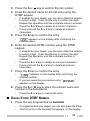
SCAN .......................................................................
ADD TO SCAN/ DELETE FROM SCAN ..........................................
PRIORITY SCAN .............................................................
GROUP SCAN (TK-3173 ONLY) ............................................
SCAN REVERT ..............................................................
FleetSync: ALPHANUMERIC 2-WAY PAGING FUNCTION ...................
SELCALL (SELECTIVE CALLING) ..............................................
STATUS MESSAGE ..........................................................
SHORT MESSAGES ..........................................................
LONG MESSAGES ...........................................................
DTMF (DUAL TONE MULTI FREQUENCY) CALLS ....................
MANUAL DIALING (KEYPAD MODELS ONLY) ..................................
STORE AND SEND ...........................................................
AUTODIAL ..................................................................
REDIAL (KEYPAD MODELS ONLY) ............................................
CONNECT/ DISCONNECT IDS (KEYPAD MODELS ONLY) .........................
DTMF SIGNALING .........................................................
STUN ......................................................................
EMERGENCY CALLS .....................................................
ADVANCED OPERATIONS ...............................................
SELECTING A TRANSMIT POWER ..............................................
TALK AROUND ..............................................................
MONITOR/ SQUELCH OFF ....................................................
SCRAMBLER ................................................................
KEY LOCK ..................................................................
TRANSCEIVER BACKLIGHT ....................................................
BACKGROUND OPERATIONS ...........................................
TIME-OUT TIMER (TOT) ....................................................
BUSY CHANNEL LOCKOUT (BCL) ............................................
BATTERY SAVER ............................................................
BATTERY STATUS INDICATOR .................................................
BEGINNING/ END OF TRANSMIT SIGNAL .......................................
vi
24
25
25
25
26
27
27
28
30
30
31
31
32
32
34
35
35
35
36
37
37
37
38
39
39
40
41
41
41
41
42
42
UNPACKING AND CHECKING EQUIPMENT
Note: The following unpacking instructions are for use by your
KENWOOD dealer, an authorized KENWOOD service facility, or the
factory.
Carefully unpack the transceiver. We recommend that you
identify the items listed in the following table before discarding
the packing material. If any items are missing or have been
damaged during shipment, file a claim with the carrier
immediately.
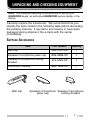
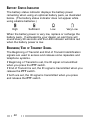
SUPPLIED ACCESSORIES
Item
Part Number
Quantity
Belt clip
J29-0701-XX
1
Speaker/ microphone jacks cap
B09-0686-XX
1
Speaker/ microphone locking
bracket
J19-5483-XX
1
Instruction manual
B62-1809-XX
1
Belt clip
Speaker/ microphone Speaker/ microphone
jacks cap
locking bracket
1
PREPARATION
BATTERY PACK PRECAUTIONS
Do not use battery packs or battery chargers not
recommended by KENWOOD.
◆ Do not recharge the battery pack if it is already fully charged.
Doing so may cause the life of the battery pack to shorten or the
battery pack may be damaged.
◆ After recharging the battery pack, disconnect it from the charger.
If the charger power is reset (turned ON after being turned OFF),
recharging will start again and the battery pack will become
overcharged.
◆ Do not use the transceiver while charging the battery pack. We
recommend you switch the transceiver power OFF while
charging is taking place.
◆ Do not charge the battery pack when the battery pack or
transceiver is wet, to avoid the risk of fire or damage. Wipe the
water from the battery pack or transceiver using a dry cloth
before charging.
◆ Do not short the battery terminals or dispose of the battery by
fire.
◆ Never attempt to remove the casing from the battery pack.
■ CHARGING THE BATTERY PACK
For charging procedures, refer to the battery charger
Instruction Manual.
2
Information concerning the (optional) Li-ion battery pack:
The battery pack includes flammable objects such as organic solvent.
Mishandling may cause the battery to rupture producing flames or
extreme heat, deteriorate, or cause other forms of damage to the battery.
Please observe the following prohibitive matters.
DANGER
•
•
•
•
•
•
Do not disassemble or reconstruct battery!
The battery pack has a safety function and protection circuit to
avoid danger. If they suffer serious damage, the battery may
generate heat or smoke, rupture, or burst into flame.
Do not short-circuit the battery!
Do not join the + and – terminals using any form of metal (such as
a paper clip or wire). Do not carry or store the battery pack in
containers holding metal objects (such as wires, chain-necklace or
hairpins). If the battery pack is short-circuited, excessive current
will flow and the battery may generate heat or smoke, rupture, or
burst into flame. It will also cause metal objects to heat up.
Do not incinerate or apply heat to the battery!
If the insulator is melted, the gas release vent or safety function is
damaged, or the electrolyte is ignited, the battery may generate
heat or smoke, rupture, or burst into flame.
Do not use or leave the battery near fires, stoves, or other
heat generators (areas reaching over 80°C/ 176°F)!
If the polymer separator is melted due to high temperature, an
internal short-circuit may occur in the individual cells and the
battery may generate heat or smoke, rupture, or burst into flame.
Do not immerse the battery in water or get it wet by other
means!
If the battery’s protection circuit is damaged, the battery may
charge at extreme current (or voltage) and an abnormal chemical
reaction may occur. The battery may generate heat or smoke,
rupture, or burst into flame.
Do not charge the battery near fires or under direct sunlight!
If the battery’s protection circuit is damaged, the battery may
charge at extreme current (or voltage) and an abnormal chemical
reaction may occur. The battery may generate heat or smoke,
rupture, or burst into flame.
3
•
•
•
•
•
•
•
Use only the specified charger and observe charging
requirements!
If the battery is charged in unspecified conditions (under high
temperature over the regulated value, excessive high voltage or
current over regulated value, or with a remodelled charger), it may
overcharge or an abnormal chemical reaction may occur. The
battery may generate heat or smoke, rupture, or burst into flame.
Do not pierce the battery with any object, strike it with an
instrument, or step on it!
This may break or deform the battery, causing a short-circuited.
The battery may generate heat or smoke, rupture, or burst into
flame.
Do not jar or throw the battery!
An impact may cause the battery to leak, generate heat or
smoke, rupture, and/or burst into flame. If the battery’s protection
circuit is damaged, the battery may charge at an abnormal
current (or voltage), and an abnormal chemical reaction may
occur. The battery may generate heat or smoke, rupture, or burst
into flame.
Do not use the battery pack if it is damaged in any way!
The battery may generate heat or smoke, rupture, or burst into
flame.
Do not solder directly onto the battery!
If the insulator is melted or the gas release vent or safety function
is damaged, the battery may generate heat or smoke, rupture, or
burst into flame.
Do not reverse the battery polarity (and terminals)!
When charging a reversed battery, an abnormal chemical
reaction may occur. In some cases, an unexpected large amount
of current may flow upon discharging. The battery may generate
heat or smoke, rupture, or burst into flame.
Do not reverse-charge or reverse-connect the battery!
The battery pack has positive and negative poles. If the battery
pack does not smoothly connect with a charger or operating
equipment, do not force it; check the polarity of the battery. If the
battery pack is reverse-connected to the charger, it will be
reverse-charged and an abnormal chemical reaction may occur.
The battery may generate heat or smoke, rupture, or burst into
flame.
4
•
Do not touch a ruptured and leaking battery!
If the electrolyte liquid from the battery gets into your eyes, wash
your eyes out with fresh water as soon as possible, without
rubbing your eyes. Go to the hospital immediately. If left
untreated, it may cause eye-problems.
•
Do not charge the battery for longer than the specified time!
If the battery pack has not finished charging even after the
regulated time has passed, stop it. The battery may generate
heat or smoke, rupture, or burst into flame.
Do not place the battery pack into a microwave or high
pressure container!
The battery may generate heat or smoke, rupture, or burst into
flame.
Keep ruptured and leaking battery packs away from fire!
If the battery pack is leaking (or the battery emits a bad odor),
immediately remove it from flammable areas. Electrolyte leaking
from battery can easily catch on fire and may cause the battery to
generate smoke or burst into flame.
Do not use an abnormal battery!
If the battery pack emits a bad odor, appears to have different
coloring, is deformed, or seems abnormal for any other reason,
remove it from the charger or operating equipment and do not
use it. The battery may generate heat or smoke, rupture, or burst
into flame.
•
•
•
5
■ USING THE LI-ION BATTERY PACK
•
•
•
Charge the battery pack before using it.
To keep the battery discharge at a minimum, remove the
battery pack from the equipment when it is not in use. Store
the battery pack in a cool and dry location.
When storing the battery pack for a long period:
1 Remove the battery pack from the equipment.
2 Discharge the battery pack, if possible.
3 Store the battery pack in a cool (below 25°C/ 77°F) and
dry location.
■ CHARACTERISTICS OF THE LI-ION BATTERY PACK
•
•
•
•
•
As the battery pack is charged and discharged repeatedly, the
battery capacity decreases.
Even if the battery pack is unused, the battery pack
degrades.
It takes a longer time to charge the battery pack in cooler
areas.
The life of battery pack is shortened when it is charged and
discharged in hotter areas. When the battery pack is stored
in a hot location, the battery pack degrades quicker. Do not
leave the battery pack in vehicles or near heating appliances.
When the battery pack operating time becomes short, even if
it is fully charged, replace the battery pack. Continuing to
charge and discharge the battery pack may result in
electrolyte leakage.
6
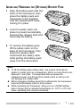
INSTALLING/ REMOVING THE (OPTIONAL) BATTERY PACK
1
Align the battery pack with the
back of the transceiver, then
press the battery pack and
transceiver firmly together
until the release latch clicks,
locking it in place.
2
Lock the safety catch into
place to prevent accidentally
pressing the release latch and
removing the battery.
3
To remove the battery pack,
lift the safety catch on the
base of the transceiver, then
press the release latch
underneath the safety catch
while pulling the battery pack
away from the transceiver.
Note:
◆ To lift the battery pack safety catch, use a piece of hardened
plastic or metal, such as a screwdriver, that is no more than 6 mm
wide and 1 mm thick. It is imperative that you place the
implement under only the lip of the safety catch so that you do
not damage the release latch.
◆ Before charging a battery pack that is attached to the transceiver,
ensure that the safety catch is firmly closed.
◆ While operating the transceiver using a Li-ion or Ni-MH battery
pack in areas with an ambient temperature of –10°C/ +14°F and
lower, operating time may be shortened.
7
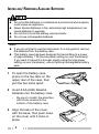
INSTALLING/ REMOVING ALKALINE BATTERIES
◆ Do not install batteries in a hazardous environment where sparks
could cause an explosion.
◆ Never discard batteries in fire; extremely high temperatures can
cause batteries to explode.
◆ Do not short circuit the battery case terminals.
◆ Do not use rechargeable batteries.
Note:
◆ If you do not plan to use the transceiver for a long period, remove
the batteries from the battery case.
◆ This battery case has been designed for transmitting at a power
of approximately 1 W (the low power setting on your transceiver).
If you want to transmit a stronger signal (using the high power
setting on your transceiver), use an optional rechargeable battery
pack.
1
To open the battery case,
press on the two tabs on the
upper rear of the case, then
pull the two halvs apart.
2
Insert 6 AA (LR6) Alkaline
batteries into the battery case.
•
3
Be sure to match the polarities
with those marked in the
bottom of the battery case.
Align the tabs of the cover
with the base, then push down
on the cover until it locks in
place.
8
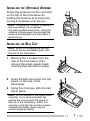
INSTALLING THE (OPTIONAL) ANTENNA
Screw the antenna into the connector
on the top of the transceiver by
holding the antenna at its base and
turning it clockwise until secure.
Note: The antenna is neither a handle, a
key ring retainer, nor a speaker/
microphone attachment point. Using the
antenna in these ways may damage the
antenna and degrade your transceiver’s
performance.
INSTALLING THE BELT CLIP
Note: When first installing the belt clip,
you must remove the battery pack from
the rear of the transceiver.
1
Remove the 2 screws from the
rear of the transceiver, then
remove the small, plastic black
covering that was held in place.
2
Insert the belt clip mount into the
space on the rear of the
transceiver.
Using the 2 screws, affix the belt
clip in place.
3
Note: Do not dispose of the plastic black
covering! If you remove the belt clip,
replace the covering into the space on
the rear of the transceiver. Either this
covering or the belt clip must be in place,
otherwise the battery pack may not
remain installed properly.
9
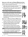
INSTALLING THE CAP OVER THE SPEAKER/ MICROPHONE JACKS
Install the cap over the speaker/ microphone jacks when not
using an optional speaker/ microphone.
1 Place the cap over the jacks so that the locking
tabs insert into the transceiver grooves.
2 While holding the cap in place, push it towards
the bottom of the transceiver until the tabs on
the cap click into place.
Note: To keep the transceiver water resistant, you must
cover the speaker/ microphone jacks with the supplied cap.
•
To remove the cap, hold the top of the cap in place
with your finger while inserting a 3 mm or smaller flat
blade screwdriver under the bottom of the cap.
Slowly slide the screwdriver in until its tip touches the
tab inside the cap, then gently pry the cap up (handle
of screwdriver moving away from the transceiver) to
remove the cap.
INSTALLING THE (OPTIONAL) SPEAKER/ MICROPHONE
1
2
3
Insert the speaker/ microphone plugs into the
speaker/ microphone jacks of the transceiver.
Place the locking bracket over the speaker/
microphone plugs so that the locking tabs
insert into the transceiver grooves.
While holding the locking bracket in place,
push it towards the bottom of the transceiver
until the tabs on the bracket click into place.
Note:
◆ When not using an optional speaker/ microphone,
install the cap over the speaker/ microphone jacks.
◆ The transceiver is not fully water resistant when
using a speaker/ microphone or headset.
•
To remove the locking bracket, push the bracket up
from the base.
10
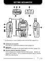
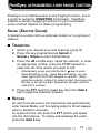
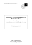
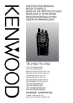
GETTING ACQUAINTED
q w
e
r
t
y
Microphone
u
!1
i
!3
o
!0
Speaker
!2
* The transceiver is also available without the DTMF keypad (!2).
q Antenna connector
Connect an (optional) antenna here {page 9}.
w Selector
Rotate to activate its programmable function {page 15}.
e Power switch/ Volume control
Turn clockwise to switch ON the transceiver. Rotate to
adjust the volume. Turn counterclockwise fully to switch
OFF the transceiver.
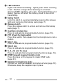
11
r LED indicator
Lights red while transmitting. Lights green while receiving
a call. Flashes orange while receiving an encoded
(2-tone, DTMF signaling, etc.) call. If programmed by your
dealer, flashes red when the battery power is low while
transmitting.
t Safety Catch
Lock this catch to avoid accidentally pressing the release
latch and removing the battery pack {page 7}.
y Release Latch
Press the release latch to unlock and remove the battery
pack {page 7}.
u Auxiliary (orange) key
Press to activate its programmable function {page 15}.
i PTT (Push-To-Talk) switch
Press this switch, then speak into the microphone to call a
station.
o Side 1 key
Press to activate its programmable function {page 15}.
!0 Side 2 key
Press to activate its programmable function {page 15}.
!1 S, A, <B, and C> keys
Press to activate their programmable functions {page 15}.
!2 DTMF keypad (keypad models only)
Press the keys on the keypad to make DTMF calls
{page 31}.
!3 Speaker/ microphone jacks
Connect an optional speaker/ microphone here {page 10}.
Otherwise, keep the supplied cap in place.
12
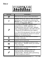
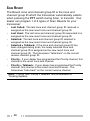
DISPLAY
Indicator
Description
This icon is not used on this transceiver.
Appears when QT, DQT, DTMF, or 2-tone
signaling is deactivated (by pressing the
Monitor key) or when Squelch is open (by
pressing the Squelch Off key).
In Conventional zones, appears when
using 2-tone or DTMF signaling. In
Trunking zones (TK-3173 only), appears
when receiving dispatch calls with a Fix ID
or Group ID (if enabled by your dealer).
(For TK-3173 transceivers, this icon will not
appear in Conventional zones if it is set to
appear for Trunking zones.)
Appears when the Talk Around function
has been activated.
Appears while scanning.
Lights when a message is stored in the
stack memory. Flashes when you receive
a new message.
Appears when the selected channel is
programmed as priority.
TK-3173 Only: Appears when the
selected group is programmed as
telephone IDs. Flashes when performing
an auto telephone search.
13
Indicator
Description
Appears when using low transmit power.
Appears when the scrambler function is
activated.
Displays the battery status. The battery
icon with all 3 strength bars represents full
power while an empty battery icon
represents very low power.
Appears when the selected zone is added
to the scanning sequence.
Appears when the VOX function has been
activated.
Appears when the AUX function has been
activated.
Appears when the OST function has been
activated.
Appears when the selected group ID or
channel is added to the scanning
sequence.
Displays the zone, group ID, and channel
numbers. Your dealer can program zone,
group ID, and channel names with up to 8
characters, in place of numbers. Also
displays received FleetSync messages.
14
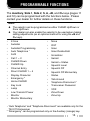
PROGRAMMABLE FUNCTIONS
The Auxiliary, Side 1, Side 2, S, A, <B, and C> keys {pages 11
and 12} can be programmed with the functions below. Please
contact your dealer for further details on these functions.
Note:
◆ The selector can be programmed as either CH/GID Up/Down or
Zone Up/Down.
◆ Your dealer can also enable the selector to be used when making
setting adjustments (as an optional method for using the <B and
C> keys).
•
•
•
•
•
•
•
•
•
•
•
•
•
•
•
•
•
•
1
2
2-tone
Autodial
Autodial Programming
Auto Telephone 1
AUX
Call 1 ~ 2
CH/GID Down
CH/GID Up
Channel Entry
Direct CH/GID 1 ~ 4
Display Character
Emergency 2
Home CH/GID
Key Lock
Lamp
Low Transmit Power
Monitor
Monitor Momentary
•
•
•
•
•
•
•
•
•
•
•
•
•
•
•
•
•
None
OST
Scan
Scan Delete/Add
Scrambler
Selcall
Selcall + Status
Squelch Level
Squelch Off
Squelch Off Momentary
Status
Talk Around
Telephone Disconnect 1
Transceiver Password
VOX
Zone Down
Zone Up
“Auto Telephone” and “Telephone Disconnect” are available only for the
TK-3173 transceiver.
“Emergency” can be programmed only on the Auxiliary (orange) key.
15
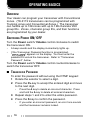
OPERATING BASICS
OVERVIEW
Your dealer can program your transceiver with Conventional
zones. (TK-3173 transceivers can be programmed with
Trunking zones and Conventional Zones.) The transceiver
can handle up to 128 zones with up to 128 channels/ 250
group IDs. Zones, channels/ group IDs, and their functions
are programmed by your dealer.
SWITCHING POWER ON/ OFF
Turn the Power switch/ Volume control clockwise to switch
the transceiver ON.
•
•
A beep sounds and the display momentarily lights up.
If the Transceiver Password function is programmed,
“
” appears on the display. You must enter the
password to unlock the transceiver. Refer to “Transceiver
Password”, below.
Turn the Power switch/ Volume control counterclockwise to
switch the transceiver OFF.
■ TRANSCEIVER PASSWORD
To enter the password without using the DTMF keypad:
1 Rotate the selector to select a digit.
2 Press the C> key to accept the entered digit and move
to the next digit.
•
3
4
Press the A key to delete an incorrect character. Press
and hold the A key to delete all entered characters.
Repeat steps 1 and 2 to enter the entire password.
Press the S key to confirm the password.
•
16
If you enter an incorrect password, an error tone sounds
and the transceiver remains locked.
To enter the password using the DTMF keypad (keypad
models only):
1 Press the DTMF keys corresponding to the password.
•
2
Press the A or # key to delete an incorrect character.
Press and hold the A or # key to delete all entered
characters.
Press the S or
•
key to confirm the password.
If you enter an incorrect password, an error tone sounds
and the transceiver remains locked.
ADJUSTING THE VOLUME
Rotate the Power switch/ Volume control to adjust the
volume. Clockwise increases the volume and counterclockwise decreases it.
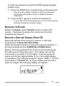
SELECTING A ZONE AND CHANNEL/ GROUP ID
Select the desired zone using the selector or the keys
programmed as Zone Up/ Zone Down.
Select the desired channel or group ID using the selector or
the keys programmed as CH/GID Up/ CH/GID Down.
Names can be programmed for zones and channels/ group
IDs with up to 8 characters each. Your dealer can set the
zone name to a length of 0 to 8 digits. Channel/ group ID
names will shorten appropriately, to fit in the 8-digit display.
For example, if the channel/ group ID name is “GRP 1” and the
zone name is “KENWOOD”, and your dealer sets the zone
name to 3-digits, the following display will appear:
17
TRUNKING ZONES (TK-3173 ONLY)
PLACING A DISPATCH CALL
1
2
Press and hold the PTT switch.
If the “Proceed” tone sounds, communication is possible;
speak into the microphone to make your call. Release the
PTT switch to receive.
•
•
For best sound quality at the receiving station, hold the
microphone approximately 1.5 inches (3 ~ 4 cm) from your
mouth.
Your dealer can deactivate the Proceed tone, if necessary.
Ask your dealer for details.
RECEIVING A DISPATCH CALL
1
When a dispatch call is received, the transceiver will
automatically change to the correct group ID and you will
hear the call.
•
2
If enabled by your dealer, the
display.
indicator appears on the
Readjust the volume as necessary.
18
PLACING A TELEPHONE CALL
1
Press the key programmed as Autodial.
•
2
Press the <B and C> keys or rotate the selector to select
your desired Autodial list number.
•
3
4
The stored entry appears on the display. Press and hold the
Side 1 key to toggle the display between the list number and
the entry name.
Press the PTT switch to make the call or the Side 2 key to
transmit the DTMF number.
When the called party responds, press the PTT switch and
speak into the microphone. Release the PTT switch to
receive.
•
5
The first entry in the Autodial list appears on the display.
Only one person can speak at a time.
To end the call, press and hold the PTT switch, then press
the key programmed as Telephone Disconnect.
RECEIVING A TELEPHONE CALL
1
When a telephone call is received, the transceiver will
automatically change to the correct group ID and you will
hear the call.
2
Press and hold the PTT switch to speak, and release it to
receive.
3
To end the call, press and hold the PTT switch, then press
the key programmed as Telephone Disconnect.
•
•
A ringer tone will sound when a call is received.
Only one person can speak at a time.
19
CONVENTIONAL ZONES
TRANSMITTING
1
2
Select the desired zone and channel using the selector
and the Zone or CH/GID keys.
Press the key programmed as Monitor or Squelch Off to
check whether or not the channel is free.
•
3
If the channel is busy, wait until it becomes free.
Press the PTT switch and speak into the microphone.
Release the PTT switch to receive.
•
For best sound quality at the receiving station, hold the
microphone approximately 1.5 inches (3 ~ 4 cm) from your
mouth.
RECEIVING
1
Select the desired zone and channel using the selector
and the Zone or CH/GID keys.
2
When you hear a caller’s voice, readjust the volume as
necessary.
•
Alternatively, you can turn the Scan function on if desired.
QUIET TALK (QT)/ DIGITAL QUIET TALK (DQT)
Your dealer may have programmed QT or DQT signaling on
your transceiver channels. A QT tone/ DQT code is a
sub-audible tone/code which allows you to ignore (not hear)
calls from other parties who are using the same channel.
When a channel is set up with a QT tone or DQT code,
squelch will only open when a call containing a matching tone
or code is received. If a call containing a different tone or
code is made on the channel you are using, squelch will not
open and you will not hear the call.
Although it may seem like you have your own private channel
while using QT/ DQT, other parties can still hear your calls if
their transceiver is set up with the same tone or code.
20
2-TONE SIGNALING
2-tone Signaling is enabled or disabled by your dealer. This
function opens the squelch only when the transceiver receives
the 2 tones programmed in your transceiver. Transceivers
that do not transmit the correct tones will not be heard.
■ TRANSMITTING
1
2
3
4
Select your desired zone and channel.
Press the key programmed as 2-tone.
Press the <B and C> keys, rotate the selector, or enter
an appropriate number using the DTMF keypad to
select the 2-tone code of the station you want to call.
Press the PTT switch and begin your conversation.
Note: If Single Tone has been activated, only the first tone of the
2-tone signal will be transmitted.
■ RECEIVING
When you receive a signal containing the correct tones,
squelch opens and you will hear the call.
•
•
•
•
•
•
The
indicator appears on the display. (This indicator will
not appear on TK-3173 transceivers if it has been set to store
Trunking zone data.)
The LED indicator flashes orange.
To mute the speaker after squelch opens, press the key
programmed as Monitor.
Your dealer can program the squelch to close again after a
specific time period elapses.
If Transpond for 2-tone Signaling is programmed, an
acknowledgment signal is returned to the calling station.
If Call Alert for 2-tone Signaling is programmed, an alert tone
will sound when the correct tones are received.
21
OPERATOR SELECTABLE TONE (OST)
You can change the preset encode and decode tones for the
selected channel. Your dealer can program up to 40 tones on
your transceiver.
To turn OST ON or OFF, press the key programmed as OST.
•
The OST indicator (
this function is activated.
) appears on the display when
To change the preset encode/decode tones:
1 Press and hold the key programmed as OST for
approximately 1 second.
•
2
3
The OST name appears on the display.
Press the <B and C> keys, rotate the selector, or enter an
appropriate number using the DTMF keypad to select your
desired encode/decode pair.
Press the Side 1, S, or key to accept the new setting
and return to normal operation.
VOICE OPERATED TRANSMISSION (VOX)
VOX can be activated or deactivated by your dealer. VOX
operation allows you to transmit hands-free. This feature can
only be used if you are using a supported headset.
When operating VOX, you must set a VOX Gain level. This
setting allows the transceiver to recognize sound levels. If the
microphone is too sensitive, it will begin transmitting when
there is noise in the background. If it is not sensitive enough,
it will not pick up your voice when you begin speaking. Be
sure to adjust the VOX Gain level to an appropriate sensitivity
to allow smooth transmission.
To set the VOX Gain level, perform the following steps:
1 Connect the headset to the transceiver.
•
The VOX function does not activate when a headset is not
connected to the accessory terminal of the transceiver.
22
2
Press the key programmed as VOX.
3
Press the <B and C> keys or rotate the selector to
increase or decrease the VOX Gain level.
•
•
4
The VOX Gain can be adjusted from levels 1 to 10.
While adjusting the gain level, speak into the headset
microphone as you would while under normal operation, to
test the sensitivity level.
•
•
5
The current VOX Gain level appears.
When the microphone recognizes a sound, the LED lights
orange. This allows you to determine a suitable level where
background noise will not activate VOX operation while
speaking into the microphone will.
The transceiver does not transmit your voice during this test
procedure.
Press the S key to save the setting.
To activate the VOX function:
1 Connect the headset to the transceiver.
•
The VOX function does not activate when a headset is not
connected to the accessory terminal of the transceiver.
2
Press and hold the key programmed as VOX for
2 seconds.
3
To turn the VOX function OFF, press and hold the VOX
key again, for 2 seconds.
•
The VOX indicator (
) appears on the display.
Note:
◆ If a speaker/ microphone is connected to the transceiver while the
VOX function is switched ON and the VOX Gain Level is configured
to a higher, more sensitive level, louder received signals may cause
the transceiver to start transmission.
◆ When you operate the VOX function, you must use an optional
KHS-1, KHS-21, or KHS-22 accessory.
23
SCAN
If the Scan function is programmed, zones or channels can be
scanned by pressing the key programmed as Scan. Scan
can be used as either Single Scan, Multi Scan, or List Scan
(TK-3173 only).
•
•
•
Single Scan monitors only the channels of the currently selected
zone, which have been added to the scanning sequence. If set
up to scan the Priority channel, the Priority channel will be
scanned even if it is not within the currently selected zone.
Multi Scan monitors all channels of every zone, which have been
added to the scanning sequence.
List Scan monitors all channels within the specified range of
zones, which have been added to the scanning sequence. If set
up to scan the Priority channel, the Priority channel will be
scanned even if it is not within any of the zones in the list.
To activate Scan, press the key programmed as Scan.
•
•
•
The
icon and “
” or the revert zone and channel/ group
ID number appear on the display.
The zone add indicator (
) will appear on the display
when the selected zone is added to the scan sequence. The
channel/ group ID add indicator (
) will appear on the
display when the selected channel/ group ID is added to the scan
sequence.
When a call is received, scanning stops and the zone and
channel/ group ID digits appear. Press the PTT switch and speak
into the microphone to respond to the call. The transceiver will
continue scanning after a predetermined time delay if the PTT
switch is released and no further signal is received.
To stop scanning, press the Scan key again.
24
ADD TO SCAN/ DELETE FROM SCAN
Press the key programmed as Scan Delete/Add, to add or
remove each channel/ group ID to or from the scan sequence.
•
The channel/ group ID add indicator (
) will appear on
the display when the selected channel/ group ID is added to the
scan sequence.
Press and hold the key programmed as Scan Delete/Add, to
add or remove each zone to or from the scan sequence.
•
The zone add indicator (
) will appear on the display
when the selected zone is added to the scan sequence.
PRIORITY SCAN
The Priority channel must be programmed in order for Priority
Scan to function.
The transceiver will automatically change to the Priority
channel when a signal is received on it, even if a signal is
being received on a normal channel.
•
The
indicator appears on the display when the selected
channel is the Priority channel.
Note: Priority cannot be programmed onto the group ID of a
Trunking zone; it can be used only on channels of Conventional
zones.
GROUP SCAN (TK-3173 ONLY)
Group Scan is useful when more than one group ID is
programmed in a zone. Group Scan is set by your dealer on
request. It scans the revert groups as well as groups that are
allowed to be scanned.
When a call is received, the group indicator shows the group
ID, and that group becomes the revert group. Simply press
the PTT switch to respond to the call.
25
SCAN REVERT
The Revert zone and channel/ group ID is the zone and
channel/ group ID which the transceiver automatically selects
when pressing the PTT switch during Scan, to transmit. Your
dealer can program 1 of 6 types of Scan Reverts for your
transceiver:
•
•
•
•
•
•
Last Called: The last zone and channel/ group ID received is
assigned as the new revert zone and channel/ group ID.
Last Used: The last zone and channel/ group ID responded to is
assigned as the new revert zone and channel/ group ID.
Selected: The last zone and channel/ group ID selected is
assigned as the new revert zone and channel/ group ID.
Selected + Talkback: If the zone and channel/ group ID has
been changed during Scan, the newly selected zone and
channel/ group ID is assigned as the new revert zone and
channel/ group ID. The transceiver “talks back” on the current
receive channel/ group ID.
Priority: If your dealer has programmed the Priority channel, this
channel is the revert zone and channel.
Priority + Talkback: If your dealer has programmed the Priority
channel, this channel is the revert zone and channel. The
transceiver “talks back” on the current receive channel.
Note: “Priority” and “Priority + Talkback” are not available for
Trunking Systems.
26
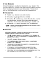
FleetSync: ALPHANUMERIC 2-WAY PAGING FUNCTION
FleetSync is an Alphanumeric 2-way Paging Function, and is
a protocol owned by KENWOOD Corporation. FleetSync
enables a variety of paging functions on your transceiver,
some of which depend on dealer programming.
SELCALL (SELECTIVE CALLING)
A Selcall is a voice call to a particular station or to a group of
stations.
■ TRANSMITTING
1
2
3
Select your desired zone and channel/ group ID.
Press the key programmed as Selcall or
Selcall + Status to enter Selcall Mode.
Press the <B and C> keys, rotate the selector, or enter
an appropriate number using the DTMF keypad to
select the ID of the station you want to call.
•
4
Alternatively, press and hold the S or
key to enter
Manual Dialing mode. Using Manual Dialing, you can
enter digits with the DTMF keypad or selector. When
using the selector, rotate it to select a digit, then press the
C> key to accept the digit. Repeat this process until the
entire ID is entered.
Press the PTT switch to make the call or the Side 2
key to page the selected recipient.
■ RECEIVING
An alert tone will sound, the transceiver will automatically
enter Selcall Mode, and the calling station’s ID will appear
when a Selcall is received.
To respond to the call, press the PTT switch and speak
into the microphone. To simply acknowledge the caller,
press the Side 2 key.
27
■ IDENTIFICATION CODES
An ID code is a combination of a 3-digit Fleet number and
a 4-digit ID number. Each transceiver must have its own
Fleet and ID number.
•
•
•
•
•
Enter a Fleet number (100 ~ 349) to make a group call.
Enter an ID number (1000 ~ 4999) to make an individual call
in your fleet.
Enter a Fleet number make a call to all units in the selected
fleet (Fleet call).
Enter an ID number to make a call to the selected ID in all
fleets (Supervisor call).
Select “ALL” Fleet and “ALL” ID to make a call to all units
(Broadcast call).
Note: The ID range may be limited by programming.
STATUS MESSAGE
You can send and receive 2-digit Status messages which may
be decided in your talk group. Status messages range from
10 to 99 (80 ~ 99 are reserved for special messages), each of
which can contain up to 16 alphanumeric characters.
A maximum of 5 received Status calls can be stored in the
stack memory of your transceiver. These saved messages
can be reviewed after reception. Depending on your dealer
settings, when the stack memory is full, either the oldest
message will be erased when a new message is received or
the new message will not be stored in the stack memory. The
icon lights when a message is stored in the stack memory.
■ TRANSMITTING
1
2
Select your desired zone and channel/ group ID.
Press the key programmed as Status to enter Status
Mode or Selcall + Status to enter Selcall Mode.
•
28
When using the Status key to enter Status Mode, the
station ID is fixed and cannot be selected. Skip to step 5.
3
In Selcall Mode, press the <B and C> keys, rotate the
selector, or enter an appropriate number using the
DTMF keypad to select the ID of the station you want
to call.
•
4
5
Press the S key to enter Status Mode.
Press the <B and C> keys, rotate the selector, or enter
an appropriate number using the DTMF keypad to
select the status ID you want to transmit.
•
6
Alternatively, press and hold the S or
key to enter
Manual Dialing mode. Using Manual Dialing, you can
enter digits with the DTMF keypad or selector. When
using the selector, rotate it to select a digit, then press the
C> key to accept the digit. Repeat this process until the
entire ID is entered.
Alternatively, press and hold the S or
key to enter
Manual Dialing mode. Using Manual Dialing, you can
enter digits with the DTMF keypad or selector. When
using the selector, rotate it to select a digit, then press the
C> key to accept the digit. Repeat this process until the
entire ID is entered.
Press the PTT switch to make the call or the Side 2
key to page the selected recipient.
•
•
Alternatively, press the Call 1 or Call 2 key to transmit
their pre-programmed status messages.
“
” appears on the display when the call has
been successfully transmitted.
■ RECEIVING
The
icon will flash and a calling ID or text message will
appear when a Status call is received.
Press any key to return to normal operation.
29
■ REVIEWING MESSAGES IN THE STACK MEMORY
1
Press and hold the key programmed as Selcall, Status,
or Selcall + Status for 1 second to enter Stack Mode.
•
2
Press the <B and C> keys or rotate the selector to
select the desired message.
•
3
The last received call ID/ stack number appears on the
display.
Press and hold the S key to toggle between the call ID/
status message and the channel name.
Press the S key to return to normal operation.
•
•
To delete the selected message, press the A or # key. To
confirm the deletion, press the S or
key.
To delete all messages, press and hold the A or # key for
key.
1 second. To confirm the deletion, press the S or
SHORT MESSAGES
To send a short message, you must connect the transceiver to
a PC. Ask your dealer for details.
•
•
Short messages can contain a maximum of 48 characters.
Received short messages are displayed the same as Status
messages. Only 1 short message can be stored in the stack
memory, along with 5 Status calls and 3 Caller IDs. and are
stored in the same stack memory.
LONG MESSAGES
To send and receive long messages, you must connect the
transceiver to a PC. Ask your dealer for details.
•
Long messages can contain a maximum of 1024 characters.
30
DTMF (DUAL TONE MULTI FREQUENCY) CALLS
MANUAL DIALING (KEYPAD MODELS ONLY)
■ METHOD 1
Press and hold the PTT switch, then enter the desired
digits using the front panel keypad.
•
If your dealer has activated the Keypad Auto PTT function,
you need not press the PTT switch while pressing the keys on
the keypad in Conventional systems. The DTMF code will be
sent automatically when you press a key.
■ METHOD 2
Enter the desired digits using the front panel keypad
(maximum of 16 digits). After entering the complete
number, press the PTT switch.
•
•
•
In Conventional systems, the DTMF code is transmitted after
pressing the PTT switch.
In Trunking systems, the DTMF code is transmitted after a
connection is established. Releasing the PTT switch before a
connection is established will stop the transmission from
occurring.
In RIC (Repeater Inter-Connect) Trunking systems, the DTMF
code is transmitted after a connection with the telephone
system is established. Press the key programmed as
Autodial, followed by the Side 2 key, to automatically
connect to the repeater and transmit the DTMF code.
Note: If you switch the power OFF before sending the number,
the number will be cleared from memory.
31
STORE AND SEND
Store and send allows you to make DTMF calls without the
need for a DTMF keypad.
1 Press the key programmed as Autodial.
•
2
•
3
“
” appears on the display.
Rotate the selector to select a digit.
Alternatively, you can enter the digits by using the DTMF
keypad (keypad models only).
Press the C> key to accept the entered digit and move to
the next digit.
•
Press the A key to delete an incorrect character. Press and
hold the A key to delete all entered characters.
4
Repeat steps 2 and 3 to enter the entire number.
5
Press the PTT switch to make the call or the Side 2 key to
page the selected recipient.
•
You can enter up to 16 digits.
AUTODIAL
Autodial allows you to store 16 names (up to 8 characters per
name) and DTMF numbers (up to 16 digits per number).
These operations can be performed with or without a DTMF
keypad.
■ STORING DTMF NUMBERS
1
Press the key programmed as Autodial Programming.
•
•
2
If programmed by your dealer, you can also press and
hold the # key for 1 second.
The first entry in the Autodial list appears on the display.
Press the <B and C> keys, rotate the selector, or enter
an appropriate number using the DTMF keypad
(01 ~ 16) to select your desired Autodial list number.
•
32
Press and hold the Side 1 key to toggle the display
between the list number and the entry name.
3
4
Press the S or key to confirm the list number.
Enter the desired name for the list entry using the
DTMF keypad.
•
•
5
Press the S key to confirm the entry.
•
6
•
If enabled by your dealer, you can also rotate the selector
to select a digit. Press the C> key to confirm the digit.
Repeat this operation until the complete number is
entered.
Press the A or # key to delete an incorrect character.
Press and hold the A or # key to delete all entered
characters.
Press the S key to confirm the entry.
•
•
8
“
” appears on the display after confirming the
entered name.
Enter the desired DTMF number using the DTMF
keypad.
•
7
If enabled by your dealer, you can also rotate the selector
to select a digit. Press the C> key to confirm the digit.
Repeat this operation until the complete name is entered.
Press the A or # key to delete an incorrect character.
Press and hold the A or # key to delete all entered
characters.
“
” appears on the display after confirming the
entered number.
If you are overwriting a previous entry, “
”
appears on the display.
Press the S or key to store the entered name and
number in the Autodial list.
•
Press the A or # key to cancel the entry.
■ DIALING STORED DTMF NUMBERS
1
Press the key programmed as Autodial.
•
•
If programmed by your dealer, you can also press the # key.
The first entry in the Autodial list appears on the display.
33
2
Press the <B and C> keys, rotate the selector, or enter
an appropriate number using the DTMF keypad
(01 ~ 16) to select your desired Autodial list number.
•
3
The stored entry appears on the display. Press and hold
the Side 1 key to toggle the display between the list
number and the entry name.
Press the PTT switch to make the call or the Side 2
key to page the selected recipient.
■ CLEARING STORED DTMF NUMBERS
1
Press the key programmed as Autodial Programming.
•
2
3
Press the <B and C> keys, rotate the selector, or enter
an appropriate number using the DTMF keypad
(01 ~ 16) to select your desired Autodial list number.
Press the A or # key.
•
4
If programmed by your dealer, you can also press and
hold the # key for 1 second.
“
” appears on the display after confirming the
entered number.
Press the S or
Autodial list.
key to delete the entry from the
REDIAL (KEYPAD MODELS ONLY)
You can redial the last number you transmitted.
1 Press the # key or the key programmed as Autodial.
•
2
3
The first entry in the Autodial list appears on the display.
Press the key followed by the 0 key to display the last
called number.
Press the PTT switch to make the call or the Side 2 key to
page the selected recipient.
Note: Switching OFF the transceiver power clears the redial
memory.
34
CONNECT/ DISCONNECT IDS (KEYPAD MODELS ONLY)
1
Press the # key or the key programmed as Autodial.
2
Connect ID: Press the key two times.
Disconnect ID: Press the key followed by the # key.
Press the PTT switch to make the call or the Side 2 key to
page the selected recipient.
•
3
The first entry in the Autodial list appears on the display.
DTMF SIGNALING
DTMF Signaling is either enabled or disabled by your dealer.
This function opens the squelch only when the transceiver
receives the DTMF code programmed in your transceiver.
Each transceiver is normally programmed with a unique code.
You will not hear calls from transceivers that are not
programmed with a matching code.
When you receive a signal containing the correct tones,
squelch opens and you will hear the call.
•
•
•
•
•
•
The
indicator appears on the display. (This indicator will not
appear on TK-3173 transceivers if it has been set to store
Trunking zone data.)
The LED indicator flashes orange.
To mute the speaker after squelch opens, press the key
programmed as Monitor.
Your dealer can program the squelch to close again after a
specific time period elapses.
If Transpond for DTMF Signaling is programmed, an
acknowledgment signal is returned to the calling station.
If Tone Alert for DTMF Signaling is programmed, an alert tone will
sound when the correct tones are received.
STUN
This function is used when a transceiver is stolen or lost.
When the transceiver receives a call containing a stun code,
either transmit mode will be disabled, or both receive mode
and transmit mode will be disabled. Stun is cancelled when
the transceiver receives a call with a revive code.
35
EMERGENCY CALLS
If your transceiver has been programmed with the Emergency
function, you can make emergency calls.
Note: Only the Auxiliary (orange) key can be programmed with the
Emergency function.
1
Press and hold the key programmed as Emergency.
•
Depending on the delay time programmed into your
transceiver, the length of time you must hold the Emergency
key will vary.
When the transceiver enters Emergency mode, the
transceiver will change to the Emergency channel and begin
transmitting based on how the transceiver is set up by your
dealer. Transmit periods are also set by your dealer.
•
2
To exit Emergency mode, press and hold the Emergency
key again.
•
If the Emergency mode completes the preset number of
cycles, Emergency mode will automatically end and the
transceiver will return to the channel that was in use before
Emergency mode was entered.
Note:
◆ Your dealer can set the transceiver to emit a tone when
Emergency mode starts and stops
◆ Your dealer can set the transceiver to emit tones and received
signals as normal or mute the speaker during Emergency
operation.
36
ADVANCED OPERATIONS
SELECTING A TRANSMIT POWER
Each channel is programmed with either high or low transmit
power by your dealer. You can change the transmit power of
only channels programmed with high transmit power.
When you can reliably communicate with other parties without
using high transmit power, select low transmit power by
pressing the key programmed as Low Transmit Power.
Each time you press Low Transmit Power, the transmit
power toggles between high and low.
•
•
The icon appears while using low transmit power.
Using low transmit power conserves battery power and reduces
the risk of interfering with other communications.
Note: Pressing Low Transmit Power while using a channel
programmed with low power causes an error tone to sound.
TALK AROUND
You may occasionally experience an interruption in service
(due to a power failure, etc.). During such an occurrence, you
can continue communication by using the Talk Around feature.
Talk Around allows you to communicate directly with other
transceivers, without the use of a repeater. However, if the
station you want to contact is too far away, or there are
geographical obstacles in the way, you may not be able to
contact the station.
Toggle Talk Around ON and OFF by pressing the key
programmed as Talk Around.
•
•
The icon appears on the display while Talk Around is active.
When using Talk Around, the receive frequency is used for both
transmitting and recieving, and the decode signaling is used for
both encoding and decoding.
37
MONITOR/ SQUELCH OFF
You can use the key programmed as Monitor/ Squelch Off to
listen to weak signals that you cannot hear during normal
operation and to adjust the volume when no signals are
present on your selected channel.
•
The icon appears on the display while Monitor/ Squelch Off is
activated.
Your dealer can program a key with one of 4 functions:
• Monitor: Momentarily press to deactivate QT, DQT,
DTMF, 2-tone, or Fleetsync Signaling. Press the key
again to return to normal operation.
• Monitor Momentary: Press and hold to deactivate QT,
DQT, DTMF, 2-tone, or Fleetsync Signaling. Release the
key to return to normal operation.
• Squelch Off: Momentarily press to hear background
noise. Press the key again to return to normal operation.
• Squelch Off Momentary: Press and hold to hear
background noise. Release the key to return to normal
operation.
■ SQUELCH LEVEL
The squelch level can be adjusted only in Conventional
operating mode:
1 Press the key programmed as Squelch Level.
•
2
3
The icon and the current squelch level appear on the
display.
Press the <B and C> keys or rotate the selector to
increase (tighten) or decrease (open) the squelch
level.
Press the Side 1, S, or key to store the new setting
and exit the squelch level adjustment.
38
SCRAMBLER
Although the scrambler function does not offer complete
privacy with your calls, it does prevent others from easily
listening in on your calls. When activated, the transceiver
distorts your voice so that anybody listening to your
conversation will not be able to clearly hear what you are
saying.
In order for members of your own group to clearly hear your
call while you are using the scrambler, all other members
must also activate the scrambler functions on their
transceivers. This distorts everybody’s voice while
transmitting and corrects the voice message on your own
transceiver when you receive the call.
To activate the scrambler, press the key programmed as
Scrambler.
•
The
icon appears on the display while the scrambler is active.
To deactivate the scrambler, press the Scrambler key again.
Note: There are 2 options for using the scrambler. Your dealer can
activate or deactivate the built-in scrambler function of the
transceiver, or they can add a more secure optional scrambler board
to your transceiver. Ask your dealer for details.
KEY LOCK
This function is used to help prevent any accidental operation
of the transceiver.
To lock the transceiver keys, press and hold the key
programmed as Key Lock for 1 second.
•
•
"
" momentarily appears on the display.
You can continue to use the following programmable functions
and/or keys (if available): Auxiliary (orange) key, Key Lock,
Side 1 key, Side 2 key, PTT switch, and Power switch/ Volume
control.
To unlock the keys, press and hold the Key Lock key again
for 1 second.
39
TRANSCEIVER BACKLIGHT
To turn the transceiver display backlight on, press the key
programmed as Lamp.
•
Pressing any key other than the PTT switch and the Power
switch/ Volume control while the backlight is on will reset the
lamp timer, allowing the backlight to remain lit for an additional
5 seconds.
To turn the display backlight off immediately, press the Lamp
key while the backlight is on.
40
BACKGROUND OPERATIONS
TIME-OUT TIMER (TOT)
The purpose of the Time-out Timer is to prevent any caller
from using a channel for an extended period of time.
If you continuously transmit for a period of time that exceeds
the programmed time set by your dealer (default is 1 minute
for Conventional and dispatch (Trunking) operation, and
3 minutes for telephone (Trunking) operation), the transceiver
will stop transmitting and an alert tone will sound. To stop the
tone, release the PTT switch.
Your dealer can program the TOT time in the range of
15 seconds to 20 minutes for Conventional operation and
15 seconds to 10 minutes for Trunking operation.
BUSY CHANNEL LOCKOUT (BCL)
When activated, BCL prevents you from interfering with other
parties who may be using the same channel that you
selected, in Conventional operating mode. Pressing the PTT
switch while the channel is in use will cause your transceiver
to emit an alert tone and transmission will be inhibited (you
cannot transmit). Release the PTT switch to stop the tone
and return to receive mode.
Note: Ask your dealer for an explanation on how BCL functions
when using QT, DQT, DTMF, 2-tone, or FleetSync signaling.
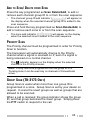
BATTERY SAVER
If activated by your dealer, the Battery Saver function will
decrease the amount of power used when a signal is not
being received and no operations are being performed (no
keys are being pressed, and no switches are being turned).
While the channel is not busy and no operation is performed for
5 seconds, Battery Saver turns ON. When a signal is received
or an operation is performed, Battery Saver turns OFF.
41
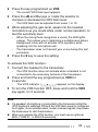
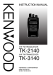
BATTERY STATUS INDICATOR
The battery status indicator displays the battery power
remaining when using an optional battery pack, as illustrated
below. (The battery status indicator does not appear while
using alkaline batteries.)
High
Sufficient
Low
Very Low
When the battery power is very low, replace or recharge the
battery pack. If activated by your dealer, an alert tone will
sound every 30 seconds and the LED indicator will blink red
when the battery power is low.
BEGINNING/ END OF TRANSMIT SIGNAL
The Beginning of Transmit and End of Transmit identification
signals are used to access and release some repeaters and
telephone systems.
If Beginning of Transmit is set, the ID signal is transmitted
when you press the PTT switch.
If End of Transmit is set, the ID signal is transmitted when you
release the PTT switch.
If both are set, the ID signal is transmitted when you press
and release the PTT switch.
42