1
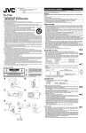
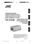
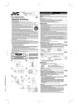
COLOR VIDEO CAMERA
TK-WD310
INSTRUCTIONS
For Customer Use:
Enter below the Serial No. which is
located on the body. Retain this
information for future reference.
Model No. TK-WD310
Serial No.
This instruction manual is made from 100% recycled paper.
LWT0127-001A
IMPORTANT SAFEGUARDS
1. Read all of these instructions.
2. Save these instructions for later use.
3. All warnings on the product and in the operating instructions
should be adhered to.
4. Unplug this appliance system from the wall outlet before cleaning. Do not use liquid cleaners or aerosol cleaners. Use a damp
cloth for cleaning.
5. Do not use attachments not recommended by the appliance
manufacturer as they may cause hazards.
6. Do not use this appliance near water - for example, near a
bathtub, washbowl, kitchen sink, or laundry tub, in a wet basement, or near a swimming pool, etc.
7. Do not place this appliance on an unstable cart, stand, or table.
The appliance may fall, causing serious injury to a child or adult,
and serious damage to the appliance.
Use only with a cart or stand recommended
by the manufacturer, or sold with the appli- PORTABLE CART WARNING
ance. Wall or shelf mounting should follow (symbol provided by RETAC)
the manufacturer’s instructions, and should
use a mounting kit approved by the manufacturer. An appliance and cart combination
should be moved with care.
Quick stops, excessive force, and uneven surS3125A
faces may cause the appliance and cart combination to overturn.
I
8. Slots and openings in the cabinet and the back or bottom are
provided for ventilation, and to insure reliable operation of the
appliance and to protect it from overheating, these openings
must not be blocked or covered. The openings should never be
blocked by placing the appliance on a bed, sofa, rug, or other
similar surface.
This appliance should never be placed near or over a radiator
or heat register. This appliance should not be placed in a builtin installation such as a bookcase unless proper ventilation is
provided.
9. This appliance should be operated only from the type of power
source indicated on the marking label. If you are not sure of the
type of power supplied to your home, consult your dealer or
local power company. For appliance designed to operate from
battery power, refer to the operating instructions.
10. For added protection for this product during a lightning storm,
or when it is left unattended and unused for long periods of
time, unplug it form the wall outlet and disconnect the antenna
or cable system. This will prevent damage to the product due to
lightning and power-line surges.
11. Do not allow anything to rest on the power cord. Do not locate
this appliance where the cord will be abused by persons walking on it.
II
12. Follow all warnings and instructions marked on the appliance.
13. Do not overload wall outlets and extension cords as this can
result in fire or electric shock.
14. Never push objects of any kind into this appliance through cabinet slots as they may touch dangerous voltage points or short
out parts that could result in a fire or electric shock. Never spill
liquid of any kind on the appliance.
15. Do not attempt to service this appliance yourself as opening or
removing covers may expose you to dangerous voltage or other
hazards. Refer all servicing to qualified service personnel.
16. Unplug this appliance from the wall outlet and refer servicing
to qualified service personnel under the following conditions:
a. When the power cord or plug is damaged or frayed.
b. If liquid has been spilled into the appliance.
c. If the appliance has been exposed to rain or water.
d. If the appliance does not operate normally by following the
operating instructions. Adjust only those controls that are
covered by the operating instructions as improper adjustment of other controls may result in damage and will often
require extensive work by a qualified technician to restore
the appliance to normal operation.
e. If the appliance has been dropped or the cabinet has been
damaged.
f. When the appliance exhibits a distinct change in performance
- this indicates a need for service.
III
17. When replacement parts are required, be sure the service technician has used replacement parts specified by the manufacturer that have the same characteristics as the original part.
Unauthorized substitutions may result in fire, electric shock, or
other hazards.
18. Upon completion of any service or repairs to this appliance,
ask the service technician to perform routine safety checks to
determine that the appliance is in safe operating
condition.
IV
Safety Precautions
FOR USA AND CANADA
CAUTION
RISK OF ELECTRIC SHOCK
DO NOT OPEN
CAUTION: TO REDUCE THE RISK OF ELECTRIC SHOCK. DO NOT REMOVE
COVER (OR BACK). NO USER-SERVICEABLE PARTS
INSIDE.REFER SERVICING TO QUALIFIED SERVICE PERSONNEL.
The lightning flash wish arrowhead symbol, within an equilateral triangle is intended to alert the user to the presence
of uninsulated "dangerous voltage" within the product's enclosure that may be of sufficient magnitude to constitute a
risk of electric shock to persons.
The exclamation point within an equilateral triangle is intended to alert the user to the presence of important operating and maintenance (servicing) instructions in the literature accompanying the appliance.
Information for USA
This device complies with part 15 of the FCC Rules. Changes or modifications not approved by JVC could void the user’s authority to operate the
equipment.
V
Due to design modifications, data given in this instruction book are subject to possible change without prior notice.
WARNING:
TO REDUCE THE RISK OF FIRE OR ELECTRIC
SHOCK, DO NOT EXPOSE THIS APPLIANCE TO
RAIN OR MOISTURE.
AVERTISSEMENT:
POUR EVITER LES RISQUES D’INCENDIE OU
D’ELECTRO-CUTION, NE PAS EXPOSER
L’APPAREIL A L’HUMIDITE OU A LA PLUIE.
INFORMATION (FOR CANADA)
RENSEIGNEMENT (POUR CANADA)
This Class B digital apparatus complies with Canadian ICES-003.
Cet appareil numérique de la Class B est conforme á la norme NMB-003
du Canada.
VI
INTRODUCTION
Thank you for purchasing this product.
(These instrustions are for TK-WD310U and TK-WD310E.)
Before beginning to operate this unit, please read the instruction
manual carefully in order to make sure that the best possible performance is obtained.
Features
Backlight compensation over a wide area is realized by the 14-bit Wide
Dynamic Range feature.
The Wide Dynamic Range feature controls the exposure time using a
maximum of 5 sampling timing for the image within a single screen.
Even when shooting in areas with large difference in lightning, subjects
with difference in brightness can be viewed in a clear and natural state.
1/3-inch high-resolution DPS device adopted as shooting element to
realize high picture quality with no smearing or blooming in areas with
high luminance. In addition, 2.5lx (during F1.2, 50%, AGC SUPER setting) is realized for minimum subject brightness.
Horizontal resolution of 480 lines (typ.) and vertical resolution of over
400 lines allow display of finely detailed video.
New device adopted for use even under strong electric field conditions.
Compatible with CS mount and VIDEO auto iris/DC auto iris.
* When using the C mount lens, C mount adapter is required.
Various settings in each menu screen are possible.
Menu settings can be performed easily using single button operations.
3 white balance modes of ATW, AWB and MANUAL are available.
ATW mode that adjusts the white balance automatically according to
the changes in lighting conditions (color temperature) or AWB/MANUAL
mode that automatically or manually adjusts and locks the white balance of specific lighting conditions can be selected.
Camera title setting and display can be made.
Compact design allows installation in narrow spaces.
2
EASY INSTALLATION
The factory default settings are intended to give easy installation. Please attach a lens, a power supply, a video cable
and mount the camera securely. You should now have good
images.
The additional information contained in this handbook is intended
to give additional flexibility to more demanding installations.
Before starting an important recording, be sure to perform a
test recording in order to confirm that a normal recording is
possible.
We do not accept liability for the loss of a recording in the
case of it becoming impossible to record due to a problem
in the video camera, VCR or video tape.
We do not accept liability for any damage to the camera in
cases when it is dropped because of incomplete installation
due to not observing the installation instructions correctly.
Please be careful when installing the camera.
Characters and symbols used in this instruction manual.
CAUTION : Cautionary notes concerning operation of the
unit.
MEMO
: Reference such as restrictions of features, etc.
: Reference page or item.
3
Contents
INTRODUCTION
Features ..................................................................................... 2
Contents ..................................................................................... 4
Operating Precautions ............................................................... 5
Names and Operations of Parts ................................................. 8
CONNECTION/INSTALLATION
Basic System ........................................................................... 13
Mounting the lens ..................................................................... 14
Connections on the back .......................................................... 16
Mounting the camera ............................................................... 18
Auto iris lens adjustment .......................................................... 20
Back focus adjustment ............................................................. 22
MENU SETTING
Menu settings ........................................................................... 24
Menu tree ................................................................................. 26
About menus ............................................................................ 27
FOCUS ADJUST screen .......................................................... 27
VIDEO ADJUST screen ........................................................... 28
WDR CUSTOM SETTINGS screen ...................................... 29
MANUAL WHITE BALANCE screen ..................................... 33
CAMERA SETTINGS screen ................................................... 34
LENS ADJUST screen .......................................................... 34
CAMERA TITLE EDIT screen ............................................... 36
FACTORY SETTINGS screen .................................................. 38
OTHERS
Troubleshooting ........................................................................ 39
Speifications ............................................................................. 40
4
INTRODUCTION
Operating Precautions
● To save energy, when it is not being used turn the system’s
power off.
● This camera has been designed for indoor use.
When you use it outdoors, be sure to use an appropriate housing.
● Do not install or use the camera in the following places.
• In a place exposed to rain or moisture.
• In a place with vapor or oil soot, for example in a kitchen.
• When the ambient temperature rises above or falls below the
acceptable range (from –10°C to 50°C).
• Near a source of radiation, X-rays, strong radio waves or magnetism.
• In a place where corrosive gasses are generated.
• In a place subject to vibration.
• In a place with excessive dirt.
● If this camera and the cables connected to this camera are used
where there are strong electromagnetic waves or where there
is magnetism present, for example near a radio or TV transmitter, power transformer or an electric motor, the picture may produce noise and the colours may be affected.
● This camera incorporates an AGC circuit. As a result, when it is
used under low light conditions, the camera sensitivity is automatically boosted and the picture may look uneven. However,
this is not a malfunction.
● When this camera is used in the ATW mode, the recorded
colours may be slightly different from the actual colours due to
the operational principles of the auto-tracking white balance circuit. However, this is not a malfunction.
● Hunting may occur depending on the used lens. However, this
is not a malfunction of the unit.
● The screen surroundings may appear dark depending on the
used lens.
5
INTRODUCTION
Operating Precautions (continued)
● The white balance (ATW) of this device is optimally set for sunlight. Proper white balance may not be achieved for artificial
lighting such as fluorescent lighting, etc.
● If you use this camera in locations where the camera is exposed to fluorescent light, a slow color change may occur.
(White balance normal = 5,400 K, range is 2,500 K to 10,000 K.)
● AGC SUPER: in this mode, ATW white balance may be inaccurate.
● White balance performance decreases under poor lighting conditions.
● Observe the following when carrying out camera maintenance.
• Turn the power OFF before proceeding to carry out maintenance.
If it is contaminated seriously, clean the contaminated part with
a cloth (or a tissue) which has been soaked in a solution of
water and a neutral detergent.
● The unit is to be powered by a DC 12 V or an AC 24 V power
supply.
The AC 24 V power supply should conform to the following:
U type : Class 2 only
E type : Isolated power supply only
● The beat may sometimes appear on the screen if gain is raised
when the line lock is in use, but the phenomenon takes place
due to the fluctuation of power frequency and is not a malfunction.
● At Low light levels, video iris lens may “Hunt”. Please adjust iris
level on lens to minimise hunting.
● Recommended range of operating temperature is 0°C to 35°C
degrees. The camera will function outside these parameters to
–10°C to 50°C degrees. But processing errors may be apparent.
6
● Line-Lock is set for 50 Hz ±0.02 Hz. If line frequency is outside
this tolerance, picture may jitter and some interference may be
visible in high contrast scenes.
● Blemishes: Small spots are normal, the camera contains compensation functions for blemishes above 120 mV (p-p) in value.
Please contact your JVC authorised dealer for further information.
7
INTRODUCTION
Names and Operations of Parts
[Front and Bottom]
2
1
4
5
3
7
6
1 Lens mount
For use with CS mount lens.
(C-mount lenses require a conversion ring.)
2 Backfocus adjustment ring
Adjusting the back focus during lens installation.
Please refer to “Back focus adjustment” on Page 22 for instructions on how to adjust the back focus.
8
3 [BF LOCK] Back focus locking screw (× 2: 2 mm)
This serves to fix the back focus-adjusting ring.
4 Camera-mounting bracket
The bracket has been attached on the bottom of the camera
before shipment. It can also be attached on the top according
to the circumstance.
To re-attach the bracket use the threaded holes at the top, with
the camera mounting bracket locking screws 7.
5 Camera-mounting screw hole (1/4 inch)
Use this hole when mounting the camera
onto a fixer, pan/tilt unit, and the like.
(Use a screw shorter than 7 mm.)
( Page 18)
MAX.
7mm
6 Rotation prevention hole
Make use of this rotation-preventive hole to prevent any fall
when mounting the camera. Make sure that the camera is securely mounted.
7 Camera mounting bracket fixing screws (× 2: M2.6 × 6 mm)
Be sure to use a 6 mm long screw.
Names and Operations of Parts
9
INTRODUCTION
Names and Operations of Parts
[Rear Panel]
8
SEE INSTRUCTION
MANUAL
DC12V
AC24V
1
2
CLASS 2 ONLY (U TYPE)
ISOLATED POWER ONLY
(E TYPE)
9
0
A
POWER VIDEO OUT
LL
SET
SELECTOR
INT
B
C
8 [DC 12V, AC 24V] Power input terminals
To input DC 12V or AC 24V power.
9 [VIDEO OUT] Video signal output connector
This BNC connector outputs a composite video signal. Connect this to the video input connector of a video monitor,
switcher, etc.
0 [POWER] Power indicator lamp
This lamp lights when power is supplied to the camera.
10
A [SET] button
During normal screen display, pressing and holding this button
for more than 2 seconds will display the MENU screen.
( Page 24)
During MENU screen display, this button is pressed to display
or enable the selected menu item. The input digit will change
when entering the camera title.
When selecting EXIT in the TOP MENU screen, pressing this
button will return to the normal screen.
B [SELECTOR] button
Used when performing menu settings.
This button is a multidirectional switch.
Pressing in a vertical direction (6 or 7) will select the menu
item.
Pressing in a horizontal direction (8 or t) will change the
set value of the item. When entering the camera title, the
input character will change.
C [INT/ LL] Selector Switch for Synchronizing System
This switch can set a synchronizing system of the camera.
INT:
This is set for internal synchronization (INT) .
LL (Line Lock):
The camera’s vertical synchronization is locked to the AC 24V
power line frequency.
When switching between multiple cameras using a switcher,
selecting this mode and adjusting the vertical phase can reduce the monitor sync disturbances occurring when the camera image is switched. (This cannot be used in regions where
the power frequency is 50 Hz (60 Hz) . ( ): TK-WD310E)
(INT: At time of factory shipment)
11
INTRODUCTION
Names and Operations of Parts
[Side Panel]
COLOR VIDEO CAMERA
IRIS
VIDEO DC
D
E
D [VIDEO/DC] Iris Selector Switch
This should be set according to the type of lens if an automatic
iris control lens is used.
VIDEO : In case of lens with EE amp built-in.
( Page 20)
DC
: In case of lens without EE amp built-in.
( Page 14)
(DC : At time of factory shipment)
E [IRIS] Iris Terminal
This is connected to an automatic iris control lens.
( Page 15)
12
CONNECTION/INSTALLATION
Basic System
System with up to 8 cameras
H
Av Pk L
ALC LEVEL
Camera 1
Power
cable
AC24V or
DC12V
COLOR VIDEO CAMERA
Video signal cable
H
Av Pk L
ALC LEVEL
Camera 2
H
ALC LEVEL
Camera 8
Av Pk L
AC24V or
DC12V
COLOR VIDEO CAMERA
AC24V or
DC12V
COLOR VIDEO CAMERA
• • • • • •
Monitor
DVR, etc.
SR-L910
REC
STOP/EJECT
REVERSE
REW
PAUSE/
STILL
REC
CHECK
OPERATE
VIDEO CASSETTE RECORDER
OPE. LOCK
PLAY
FF
COUNT/
CLOCK
MENU
TIME
MODE
TIMER
REC
SHIFT/TRACKING
RESET
/CANCEL
SET/V.LOCK
AL/PL
RESET
Monitor
Switcher
13
CONNECTION/INSTALLATION
Mounting the lens
Mount the lens according to the procedures described below.
Lens mount
1.
(b)
F
(c)
3.
4.
COLOR VIDEO CAMERA
IRIS
IRIS
VIDEO DC
VIDEO DC
1 3
5.
1
2 4
3
Ferrite core
4
2
14
2.
1.
Before mounting a lens, check whether it is CS-mount lens.
Dimension (b) of the lens shown in the illustration must be as
shown in the table below. If (b) exceeds the value in the table,
it may damage the inside of the camera or correct mounting
may be impossible; never use such lenses. The F mark indicates a focal point.
Lens
CS mount lens
Flange back (c)
12.5mm
Dimension (b)
5.5mm or less
* When using the C-mount lens, use the conversion ring
(CM46633-001, MOUNT ADAPTOR).
2.
Attach the included ferrite core to the lens cable. Please attach it as close to the camera as possible.
3.
Mount the lens on the camera by turning the lens clockwise.
Adjust its position.
4.
When using an auto-iris lens with an EE amplifier, turn the
switch to the “VIDEO” side. When no EE amplifier is equipped,
turn the switch to the “DC” side.
5.
If the lens has an auto-iris mechanism, connect the lens cable
after checking the pin arrangement.
If the lens cable has a different type of plug, use the 4-pin plug.
[4-pin plug part no: SCV2859-001]
Contact your dealer of purchase concerning the 4-pin plug.
Pin No.
1
2
3
4
Lens DC IRIS
(does not contain EE amplifier)
Brake –
Brake +
Drive +
Drive –
VIDEO IRIS
(contain EE amplifier)
9V [max 50mA]
NC
VIDEO
GND
15
CONNECTION/INSTALLATION
Connections on the back
● Turn off the power supply to all components before making
connections.
Power supply (DC 12 V or AC 24 V)
SEE INSTRUCTION
MANUAL
DC12V
AC24V
1
2
CLASS 2 ONLY (U TYPE)
ISOLATED POWER ONLY
(E TYPE)
POWER VIDEO OUT
LL
SET
SELECTOR
INT
Monitor
Video signal cable (BNC)
Connect the coaxial cables (BNC) to the VIDEO OUT connector (BNC).
16
Power supply (DC 12 V or AC 24 V)
Connect the DC 12 V or the AC 24 V power supply to the DC
12V/AC 24V terminals. To prevent connection errors or a cable
disconnection, we recommend the use of lug plates for the connections.
The following table shows the connection distances and connection cables provided that 2-conductor VVF cables (vinyl-insulated vinyl sheath cables) are used.
Maximum extension
(reference)
Conductor diameter
100 m
260 m
410 m
500 m
1.0φmm 1.6φmm 2.0φmm 2.6φmm
and more and more and more and more
Memo
● If thin cables are used (i.e. with a high resistance), a significant voltage drop will occur when the unit is at its maximum
power consumption. Either use a thick cable to restrict the
voltage drop at the camera side to below 10%, or place the
power supply near to the camera. If voltage drop occurs during operation, the performance will be unstable.
● Attach the cable conductors so that they do not come into
contact with the drop prevention wires.
● Do not allow input from both a DC 12 V and AC 24 V power
supply at the same time.
● When using a DC 12 V power supply, ensure that the polarities of the cable are correct.
● The AC 24 V power supply should conform to the following:
U type: Class 2 only
E type: Isolated power supply only
17
CONNECTION/INSTALLATION
Mounting the camera
Camera mounting
screw hole
Camera mounting
bracket
Rotation prevention hole
When mounting the camera on a fixer, pan/tilt, etc., use the camera mounting screw hole located on the camera-mounting bracket.
CAUTION:
Use the screw with a length shorter than
7mm from a camera-mounting face.
MAX.
7mm
Furthermore, make use of the rotation prevention hole to prevent
the camera from falling and securely mount the camera.
Special precautions must be taken for mounting the camera on a
wall or a ceiling. We are not liable for any damage caused by improper installation.
18
SEE INSTRUCTION
MANUAL
DC12V
AC24V
1
2
6mm
CLASS 2 ONLY (U TYPE)
ISOLATED POWER ONLY
(E TYPE)
POWER VIDEO OUT
LL
SET
2mm
SELECTOR
INT
M3 × 6
Fall Prevention
• Exercise maximum caution when installing the unit to the wall
or ceiling. You should not engage in the installation work yourself. Ask a professional to do the job, since the fall of the unit
can result in injuries and accidents.
• When installing the unit on a fixer, Pan/Tilt unit, etc., make sure
to install it firmly using a rotation-preventing hole provided to
prevent fall.
• To prevent fall, connect the unit to a section with sufficient
strength (ceiling slab or channel) using a fall prevention wire
such as a wire chain and the like. Use the black screw on the
back of the unit for installation.
Pay utmost attention to the length of the wire, too.
• Specified screw (M3 × 6 mm)
Never use any screw longer than the specified length as the
inside can be damaged.
19
CONNECTION/INSTALLATION
Auto iris lens adjustment
Connect the camera according to the connection method, turn it
on, display an image on the monitor, and check the image. The
white balance adjustment mode is selected. Page 32 “WHITE
BALANCE”
The camera has been factory-adjusted to the best position, but it
may need to be adjusted according to the object conditions or combination of lenses. If the image is unnatural, adjust it as follows:
(Also read the instruction manual of the lens.)
For video auto iris lens (auto iris lens with built-in
EE amp)
Set the VIDEO/DC switch on the side of the unit to “VIDEO” and
adjust the LEVEL volume on the lens.
H
Av Pk L
ALC LEVEL
Level adjustment
ALC adjustment
(Does not operate)
20
COLOR VIDEO CAMERA
• LEVEL adjustment
Monitor screen
Too bright
Too dark
LEVEL turning direction
Counterclockwise (Toward L)
Clockwise (Toward H)
Memo
● If the sensitivity adjustment LEVEL is turned excessively to
L, the sensitivity increases because of the AGC function of
the camera, and the image looks grainy.
● At Low light levels, video iris lens may “Hunt”. Please adjust
iris level on lens to minimise hunting.
For DC auto iris lens (auto iris lens without built-in
EE amp)
Set the VIDEO/DC switch on the side of the unit to “DC” and
adjust the LEVEL in the LENS ADJUST screen. ( Page 34)
21
CONNECTION/INSTALLATION
Back focus adjustment
Be sure to make back-focus adjustments when changing the lens
mounting method or using a different lens.
● To make accurate back focus adjustments, carry out adjustments
in a state where the lens iris is released.
To open the lens iris, set MODE in the FOCUS ADJUST menu
screen to ON. ( Page 27)
● The auto iris lens may operate under extremely bright conditions (7000lx or higher). In this case, use an ND filter to adjust
the amount of light.
(The ND fiter acts to reduce the amount of incident light entering the lens evenly over the entire wavelength band.)
Lens focus ring
Back focus adjust ring
Back focus locking screws
Phillips screwdriver
Memo
If the iris cable length of the lens is insufficient when turning
the back focus adjustment rings, lock the back focus locking
screws, turn the lens and loosen the back focus locking screws
again for achieving back focus.
22
• With a fixed-focus lens
If the focus can not be adjusted correctly by rotating the lens focus
ring, adjust the back focus as follows.
1.
Loosen the back focus locking screws by turning it counterclockwise ( ) with a Phillips screwdriver. (2 locations)
2.
3.
4.
5.
Shoot a pattern closely.
Turn the lens focus ring to ∞.
Turn the back focus adjustment ring to focus at the best point.
Tighten the back focus locking screws by turning it clockwise
( ). (2 locations)
• With a zoom lens
If the image is out of focus when zooming (telephoto wide-angle),
adjust the camera as follows:
1.
Loosen the back focus locking screws by turning it counterclockwise ( ) with a Phillips screwdriver. (2 locations)
2.
3.
Shoot a comparatively dark scene with thin lines.
4.
Set the lens to the maximum wide-angle position, and turn
the back focus ring to adjust the focus.
(Repeat steps 3. and 4. two or three times.)
5.
Tighten the back focus locking screws by turning it clockwise
( ). (2 locations)
Set the lens to the maximum telephoto position, and adjust
the lens focus.
23
MENU SETTING
Menu settings
SEE INSTRUCTION
MANUAL
DC12V
AC24V
1
2
CLASS 2 ONLY (U TYPE)
ISOLATED POWER ONLY
(E TYPE)
POWER VIDEO OUT
LL
SET
SELECTOR
INT
SELECTOR
button
SET button
Cursor
Operation
———
ME N U — — —
F OCU S A D J U S T . .
V I D EO A D J US T..
C AM E R A S E T T I N G S . .
F A C T OR Y S E T T I N GS . .
EX I T
1. Press and hold the SET button
for more than 2 seconds.
● The MENU screen appears.
2. Press the SELECTOR button in
Submenu (“..” displayed
at the end.)
— — — V I D E O A D J U ST — — —
WD R M O D E
A G C M OD E
WH I T E B A L A N C E
COL OR L E VE L
E N HA NC E L E V E L
EX I T
24
MO D E 2
L OW
A TW
N O R MA L
N O R MA L
the vertical direction (6 or 7)
and move the cursor (>) to the
desired submenu.
3. Press the SET button
● The selected submenu screen
appears.
— — — V I D E O A D J U ST — — —
W D R M OD E
A G C M OD E
WH I T E B A L A N C E
COL OR L E VE L
E N HA NC E L E V E L
EX I T
MO D E 2
L OW
A TW
N O R MA L
N O R MA L
4. Press the SELECTOR button in
the vertical direction (6 or 7)
and move the cursor (>) to the
desired item.
5. Press the SELECTOR button in
— — — V I D E O A D J U ST — — —
W D R M OD E
A G C M OD E
WH I T E B A L A N C E
COL OR L E VE L
E N HA NC E L E V E L
EX I T
MO D E 2
H I GH
A TW
N O R MA L
N O R MA L
the horizontal directional (8 or
t) and change the set value.
To change the set value of multiple items, repeat steps 4. and
5. above.
6. Exit the menu screen.
— — — V I D E O A D J U ST — — —
W D R M OD E
A G C M OD E
WH I T E B A L A N C E
COL OR L E VE L
E N HA NC E L E V E L
EX I T
———
MO D E 2
H I GH
A TW
N O R MA L
N O R MA L
ME N U — — —
F OC U S A D J U S T . .
V I DEO A D J US T..
C AME R A S E T T I N G S . .
F A C T O R Y S E T T I N GS . .
EX I T
Move the cursor (>) to EXIT of
the menu screen and press the
SET button.
7. Return to the normal screen.
Move the cursor (>) to EXIT of
the MENU screen and press the
SET button.
● The screen returns to the normal screen (screen with no
menu display).
Memo
When returning to the normal screen from the TOP MENU
screen by selecting EXIT, the menu settings will be stored
in the unit memory.
25
MENU SETTING
Menu tree
The menu screens are structured as shown below.
Page 27
— — — FOCUS
A D J U ST
MOD E
EX I T
———
OF F
Page 28
———
ME N U — — —
FOCUS A D J US T..
V I DEO A D J US T..
C AM E R A S E T T I N G S . .
F A C T OR Y S E T T I N GS . .
EX I T
Page 29
— — — V I D E O A D J U ST — — —
MO D E 2
L OW
A TW
N O R MA L
N O R MA L
WD R MOD E
A G C MOD E
WH I T E B A L A N C E
COL OR L E VE L
E N HA NC E L E V E L
EX I T
— — W D R C U S TO M S E T T I N G S — —
WD R B I A S
– 36
WD R
E X P. B I A S
WD R
–8
36
LI MIT
0
25
36
–18
–4
18
BR I G HT
10 0
104
15 0
EX I T
Page 34
Page 33
— — — CA M E R A
SET T I NG S — — —
L E NS A D J U S T ..
C A ME R A T I T L E
C A ME R A T I T L E
Normal screen
— — M A N UA L W H I T E BA L A N C E — —
R–B
B L UE
OFF
ED I T
RED
EXI T
V PHA SE
0
84
104
EX I T
Page 34
— — — L E NS A DJ US T — — —
Page 38
— — — F A C T OR Y
DC
OFFS ET
100
S ET T I N GS — — —
120
150
EX I T
CA NC E L
CL EAR
Memo
● When selecting an item with “..” at the end, the submenu
screen will appear.
● When selecting EXIT in each screen, the screen will return
to the previous screen.
When selecting EXIT in the MENU screen, the screen will
return to the normal screen.
26
About menus
FOCUS ADJUST ........... Used during focus adjustment of the auto
iris lens.
( Page 27)
VIDEO ADJUST ............ Sets the wide dynamic range, gain, color
temperature, white balance, etc.
( Page 28)
CAMERA SETTINGS .... Sets the DC iris, camera title and vertical
phase.
( Page 34)
FACTORY SETTINGS ... Restores the menu settings to the factory settings.
( Page 38)
FOCUS ADJUST screen
MODE
Default setting: OFF
Used during focus adjustment of the auto iris lens.
When set to ON, the focus adjustment accuracy is increased by
forcing the iris open and with a shallower focal point.
Memo
When exiting the FOCUS ADJUST screen, MODE will automatically be set to OFF.
27
MENU SETTING
VIDEO ADJUST screen
WDR MODE
Default setting: MODE2
Setting of the wide dynamic range (WDR) is performed.
CUSTOM : Manually adjusts the wide dynamic range.
Pressing the SET button will display the WDR CUSTOM SETTINGS screen. ( Page 30)
MODE1
MODE2
MODE3
MODE4
FLUOR
:
:
:
:
When shooting in a bright area outdoors
Standard video
To brighten the video taken indoors
To brighten areas with little luminance in video with
large difference in brightness
(When moving from dark indoors to outdoors during
shooting)
: For video taken under lighting (fluorescent lighting,
etc.) that synchronizes with commercial electrical
power supply frequency resulting in periodical change
in colors
(When in a 60Hz area, set to LL (Line Lock).)
( Pages 11, 35)
Memo
● The Wide Dynamic Range feature controls the exposure time
using up to 5 sampling timing within a single screen according to the brightness of the subject. With the Wide Dynamic
Range feature, the subject with a large difference in brightness with the remainder of the screen can be viewed in a
clear, natural state even when shooting in areas with large
difference in lighting (such as indoors easily influenced by
backlight, afternoon sun, etc., entrances and near windows).
● Set the mode by first checking under the usage environment.
28
WDR CUSTOM SETTINGS screen
The Wide Dynamic Range (WDR) is adjusted manually.
Operation
1. Display the VIDEO ADJUST
— — — V I D E O A D J U ST — — —
C U S T O M ..
L OW
A TW
N O R MA L
N O R MA L
WD R MOD E
A G C MOD E
WH I T E B A L A N C E
COL OR L E VE L
E N HA NC E L E V E L
EX I T
screen. ( Page 24)
2. Select WDR MODE and press
3.
— — W D R C U S TO M S E T T I N G S — —
WD R B I A S
– 36
WD R
E X P. B I A S
WD R
–8
0
25
–18
–4
BR I G HT
10 0
104
EX I T
Cursor
36
4.
LI MIT
Set value
36
18
15 0
5.
6.
the SELECTOR button in the
horizontal direction (8 or t) to
change the setting to CUSTOM.
Press the SET button.
● The WDR CUSTOM SETTINGS screen will appear.
Press the SELECTOR button in
the vertical direction (6 or 7)
and move the cursor (>) to the
item to set.
Press the SELECTOR button in
the horizontal direction (8 or t)
to change the set value.
To exit setting, select EXIT and
press the SET button.
● The screen returns to the
VIDEO ADJUST screen.
Memo
● WDR custom mode allows manual adjustment. (These are
overwritten if other modes are selected.)
● When exiting the WDR CUSTOM SETTINGS screen without changing settings, MODE1 will be automatically selected
for WDR MODE.
29
MENU SETTING
VIDEO ADJUST screen (continued)
Item
WDR BIAS
WDR LIMIT
EXP. BIAS
WDR BRIGHT
30
Content
Sets the low/mid luminance level of the Wide
Dynamic Range
● To brighten video with low/mid luminance:
Increase the value
● To darken video with low/mid luminance:
Decrease the value
[Setting range: -36 ~ -8 ~ 36]
Sets the maximum value of the Wide Dynamic Range
● To shoot a subject with large difference in
brightness:
Increase the value
[Setting range: 0 ~ 25 ~ 36]
Adjusts the output properties for the luminance
level of the subject
● To further sharpen a dark subject:
Increase the value
● To further sharpen a bright subject:
Decrease the value
[Setting range: -18 ~ -4 ~ 18]
Adjusts the brightness of the entire video.
● To further brighten the entire video:
Increase the value
[Setting range: 100 ~ 104 ~ 150]
AGC MODE
Default setting: LOW
Sets the maximum gain of AGC (Auto Gain Control).
OFF
LOW
HIGH
SUPER
:
:
:
:
When the AGC feature is not in use
When there is a shortage of light
When there is an extreme shortage of light
When there is a shortage of light even when setting to
HIGH
Memo
● When raising the gain, noise will appear in the screen for
dark areas.
● When in a dark area and setting AGC MODE to SUPER:
• Red and blues colors as well as residual images may appear for subjects with motion.
• Video may temporarily lock or noise may be noticeable.
• The entire screen may temporarily change from a dark to
a bright state.
• When especially dark, depending on light intensity, the Wide
Dynamic Range (WDR) feature will not function.
(The WDR feature will function in normal light intensities.)
• The right edge of the screen may temporarily jiggle.
31
MENU SETTING
VIDEO ADJUST screen (continued)
WHITE BALANCE
Default setting: ATW
The white balance adjustment mode is selected. White balance
can be adjusted for lighting with color temperature in the range
between 2,500K and 10,000K.
ATW
: The unit will be in the Auto Tracking White Balance mode.
The white balance will be adjusted automatically according
to the color temperature of the lighting.
AWB (SET) : When pressing the SET button (under 1 second), the white
balance will be adjusted automatically for the current lighting
(color temperature).
The result of the white balance automatically adjusted will
be stored in the unit memory.
Use this setting when using the white balance that has been
adjusted automatically.
MANUAL.. : Use this setting when manually adjusting the white balance
for the current lighting (color temperature).
When pressing the SET button, the screen for manually adjusting the white balance appears. ( Page 33)
The result of the white balance manually adjusted will be
stored in the unit memory.
Use this setting when using the white balance that has been
adjusted manually.
Memo
● When adjusting the white balance for AWB (SET) or MANUAL, fill
the entire screen with a white subject (such as paper, cloth, etc.).
● AWB (SET) data will be cleared when changing to another
mode (ATW, MANUAL).
● If proper colors cannot be achieved in the ATW mode, use
the AWB (SET) or MANUAL mode.
● In some cases, proper white balance may not be achieved
even in the MANUAL mode for artificial lightning such as
fluorescent lighting, etc.
32
MANUAL WHITE BALANCE screen
If the entire screen appears to be reddish or bluish in color as the
result of automatic white balance adjustment, manually adjust the
white balance.
— — — V I D E O A D J U ST — — —
WD R MOD E
A G C MOD E
WH I T E B A L A N C E
COL OR L E VE L
E N HA NC E L E V E L
EX I T
MO D E 2
L OW
MAN U AL..
N O R MA L
N O R MA L
Preparation
Fill the entire screen with a white
subject (such as paper, cloth, etc.).
Operation
1. Display the VIDEO ADJUST
screen. ( Page 24)
2. Set WHITE BALANCE to
— — M A N UA L W H I T E BA L A N C E — —
R–B
B L UE
RED
EXI T
Set value
Memo
The result of the white
balance adjusted manually will be stored in the
unit memory.
To use the manually adjusted white balance, set
WHITE BALANCE to
MANUAL.
MANUAL and press the SET
button.
● The MANUAL WHITE BALANCE screen will appear.
3. Press the SELECTOR button in
the vertical direction (6 or 7)
and move the cursor (>) to R-B.
4. Press the SELECTOR button in
the horizontal direction (8 or
t).
● Pressing in the 8 direction will
increase bluish tint.
● Pressing in the t direction will
increase the reddish tint.
5. To end adjustment, press the
SELECTOR button in the vertical direction (6 or 7) to select
EXIT and press the SET button.
33
MENU SETTING
VIDEO ADJUST screen (continued)
COLOR LEVEL
Default setting: NORMAL
The color level of video signals is adjusted.
● To lighten colors: decrease the value.
● To darken colors: increase the value.
[Setting range: -5 ~ NORMAL ~ 5]
ENHANCE LEVEL
Default setting: NORMAL
The aperture control/contour level of the video signals is adjusted.
● Soften video: decrease the value.
● Sharpen video: increase the value.
[Setting range: -5 ~ NORMAL ~ 5]
CAMERA SETTINGS screen
LENS ADJUST screen
This setting is performed when using the DC auto iris lens.
Settings for controlling the DC auto iris operation of the lens are
performed.
Operation
1. Display the CAMERA SET— — — L E NS
DC
A DJ US T — — —
OFFS ET
100
120
150
EX I T
Item
34
Set value
TINGS screen. ( Page 24)
2. Select LENS ADJUST and press
the SET button.
● The LENS ADJUST screen
appears.
3. Press the SELECTOR button in
the horizontal direction (8 or t)
to change the set value. Pressing and holding the button will
continuously change the value.
4. When selecting EXIT and pressing the SET button, the screen
will return to the CAMERA SETTINGS screen.
Item
DC OFFSET
Content
Standard level (brightness) for controlling the DC
auto iris operation is set.
Increasing the value: the screen will become darker
[Setting range: 100 ~ 120 ~ 150]
Memo
● Depending on the lens, hunching may occur when setting
this value too high. In this case, lower the value.
CAMERA TITLE
Default setting: OFF
Whether to display the camera title is set.
OFF : Camera title is not displayed.
ON : Camera title is displayed.
V PHASE
Vertical phase during line lock is adjusted. The vertical phase can
be adjusted to other cameras. This setting is enabled when the LL/
INT switch on the back of the unit is set to LL.
———
CA M E R A
SET T I NG S — — —
L E NS A D J U S T ..
C A ME R A T I T L E
C A ME R A T I T L E E D I T
V
OFF
PHA SE
0
84
1 04
EX I T
Set value
● Press the SELECTOR button in
the horizontal direction (8 or t)
to set. Pressing in the button to
the right (t) will advance the
phase and pressing to the left
(8) will delay the phase.
35
MENU SETTING
CAMERA SETTINGS screen (continued)
CAMERA TITLE EDIT screen
Up to 24 characters can be entered for the camera title. The entered camera title will appear on the bottom left of the screen when
the CAMERA TITLE menu item is set to ON.
Operation
———
CA M E R A
SET T I NG S — — —
L E NS A D J U S T ..
C A ME R A T I T L E
C A ME R A T I T L E E D I T
OFF
1. Display the CAMERA SETTINGS screen. ( Page 24)
2. Press the SELECTOR button in
V PHA SE
0
84
1 04
EX I T
3.
1st character
4.
5.
To correct a character, press
the SET button to display the
character to correct in
purple, press the SELECTOR button in the horizontal
direction (8 or t) to
change the character.
36
6.
7.
the vertical direction (6 or 7)
and move the cursor (>) to select CAMERA TITLE EDIT.
Press the SET button.
● The 1st character will appear
in purple and input will be allowed.
Press the SELECTOR button in
the horizontal direction (8 or t)
and select the desired character.
Press the SET button to confirm
the 1st character. The 2nd character will then appear in purple.
Repeat steps 4. and 5. above to
enter up to 24 characters.
To end character entry, press the
SELECTOR button in the vertical direction (6 or 7) and move
the cursor (>) to another item.
Allowed characters
8 direction (SELECTOR button) t direction
Space
Pressing the SELECTOR button in the t direction will select
the character on the right and pressing in the 8 direction will
select the character on the left. Pressing and holding the button
will continuously change the character selected.
Memo
When CAMERA TITLE is set to ON, a background the width of 1
character is displayed, even when there is no camera title entered.
If a CAMERA TITLE of more than 1 character is entered, a
background the width of 24 characters is displayed.
37
MENU SETTING
FACTORY SETTINGS screen
Returns set values to their factory settings.
Operation
———
ME N U — — —
F OC U S A D J U S T . .
V I DEO AD J US T..
C AM E R A S E T T I N G S . .
F AC T OR Y S E T T I NGS . .
EX I T
Cursor
— — — F A C T OR Y
CA N C E L
CL E A R
38
S ET T I N GS— — —
1. Display the FACTORY SETTINGS screen. ( Page 24)
2. Press the SELECTOR button in
the vertical direction (6 or 7)
and move the cursor (>) to
CLEAR.
3. Press the SET button.
● Settings including the camera
title will be restored to the factory settings and the screen
will return to the MENU
screen.
* Select CANCEL and press the
SET button to return to the
MENU screen without changing settings.
4. Exit the menu screen.
Select EXIT within the MENU
screen and press the SET button to return to the normal
screen.
OTHERS
Troubleshooting
Symptom
Remedy
The operation becomes un- Drop in voltage of the power supply can
be considered. Check the length and thickstable
ness of the power supply cable.
( Page 17)
The auto iris will not operate Set the VIDEO/DC switch on the side of
unit according to the type of auto iris lens
used.
( Pages 20, 21)
There is noise in the screen Lower the gain using the AGC MODE
or increase in residual images menu item.
SUPER
HIGH
LOW
OFF
(MAX)
(MIN)
Gain
( Page 29)
The colors of the screen are When using in an environment where there
are changes in the light source, set the
not natural
WHITE BALANCE menu item to ATW.
( Page 32)
Set the WHITE BALANCE menu item to
White balance adjusted
AWB or MANUAL.
automatically/manually
( Page 32)
cannot be used
The camera title will not ap- Set the CAMERA TITLE menu item to ON.
( Page 35)
pear
The vertical phase cannot be When adjusting the vertical phase during
adjusted using the V PHASE line lock, set the LL/INT switch on the back
of unit to LL.
menu item
( Page 35)
39
OTHERS
Speifications
Image pickup device
Number of effective pixeis
Synchronizaton method
Scanning frequency
:
:
:
:
1/3 type WDR digital image device
380,000 pixels ((H) 720 × (V) 540)
Internal,Line lock
U Type (H) 15.734 kHz, (V) 59.94 Hz
E type (H) 15.625 kHz, (V) 50.0 Hz
Resolution
: 480 TV lines (H)
VIDEO OUT
: Composite video signal
1 V(p-p), 75Ω (BNC)
Video S/N ratio
: 48 dB (AGC OFF)
Minimum required illumination : 2.5 lx (50%, F1.2, AGC SUPER,
WDR MODE 2)
Lens mount
: CS mount
Power supply
: AC 24 V ` 50 Hz/60 Hz
DC 12 V
Power consumption
: U type Approx. 5.7 W
E type Approx. 400 mA
Ambient temperature
: –10°C to 50°C (operation)
0°C to 35°C (recommended)
Mass
: 330 g
Accessory
: Instructions ........................ 1
Ferrite core ........................ 1
Design and specifications are subject to change without notice.
40
External Dimensions (Unit: mm)
U1-32
107
95
50
7.5
57.5
50
COLOR VIDEO CAMERA
TRIPOD BASE
33
1/4-20UNC
MOUNTING HOLE
41
TK-WD310 COLOR VIDEO CAMERA
VICTOR COMPANY OF JAPAN, LIMITED
is a registered trademark owned by VICTOR COMPANY OF JAPAN, LTD.
is a registered trademark in Japan, the U.S.A., the U.K. and other countries.
© 2004 VICTOR COMPANY OF JAPAN, LIMITED
Printed in Japan
LWT0127-001A