1
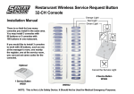
Wireless Service Bell S1
Contents
Structure of the Manual(This manual consists of following
sections)
Section 1 Installation ……………………………………1
I.
System Specifications ……………………….....1
II.
Packing and Accessories Instruction ………....2
III.
System Connecting Diagram ……………….....5
Section 2 Main board Installation ……………..…......5
I.
Main board Overview ………………………......5
II.
Suspension Holder Installation ……………......6
III.
Labeling Table Number Logo on Main
board…………………………. ……………….....8
IV.
Main board Power Adaptor Installation ……....10
Section 3 Service Button Installation ……..…….…..10
I.
Service Button Overview Introduction …….......10
II.
Battery Installation ……………………………....10
III.
Labeling Table Number Logo on Service
button ……………………………………………..11
IV.
Service Button Stand Installation ……………...12
Section 4 Main board Configuration ……..……….….13
I.
Main board Receiver DIP Switch Setting
Introduction ……………………………………....15
II.
Ring Volume Setting ……………..……………....15
III.
Ring Types Setting………………..……………....15
IV.
Tie-in Key Model Setting……….………………….16
V.
Ring Times Setting ……………………………….16
VI.
System Receiving Range Setting ……………….16
Section 5 Service Button Configuration ………………17
I.
Service Button DIP Switch Setting Instruction ….19
II.
Service Button Table Number Setting …………..19
III.
Service Button Transmitting Range Setting……..21
Section 6 System operating Instruction ……………….21
I.
Service Requirements …………………………..…21
II.
Canceling Service Method ………………………..22
Section 7 Daily Usage and Maintenance ……………….22
I.
Daily Testing ……………………………….…..…..22
II.
Usage Cautions …………………...…………..…..24
AC100~240 Power Jack
Section 1 Installation
Part I. System Specifications
Environment
Requirements
S1 Wireless Service Bell Main board (S1)
Product Spec
Operating Humidity 10% - 90% without
congealment
Operating Voltage: DC5V
Receiver
Operating Current: 200mA
Model: S1
Standby < 30Ma
Dimension:
Full Load < 35mA
Weight: 495g
Power Cable: 1.5M
Electronic
Characteristic
Speaker(Full duplex)
Impedance: 8Ω±15%
Distortion Rate: 5%MAX
Max dB: 89 ±3dB
Frequency Range: 50Hz ~10KHz
Power Indicator
Contents:
Message Indicator
Table Indicator x 32 Units
Startup Current: 600mA
Max Output Power: 0.5W
Service Button x 32 Units
Receiving Indicator
LED Indicator
(32°F - 122°F)
Name: Wireless Service Bell Main board
260(L) × 165(W) × 40(H) (mm)
Button
Operating Temp 0°C - 50°C
Packing Contents
Wireless Service Bell Receiver (S1)
User’s Manual
S1 Table no. Logo
1
Service Button Table no. Logo
Main board Receiver Location Map
Button Clamp
Logo Clamp
DC5V 1.5A Power Adaptor
Pen for Logo
Electronic
Characteristic
Packing Contents
Button
Product Spec
Contents
Operating Temp 0°C - 50°C
Environment
(32°F - 122°F)
Requirements
Operating Humidity 10% - 90% without
congealment
2
Multi
Functional
Service
Model: AB400
Dimension:
60(H)
×45(W)×
Weight: 31g
Dimension:60(L) ×45(W) × 23(H)(mm)
Wireless Service Button (AB100)
Screws
23(H)(mm)
Model: AB100
Service Button x 1 unit
DC12V Battery
Button
Name: Wireless Service Button
Weight: 31g
Working status < 10mA
Name:
Main board Fixed Screws
Product Spec
Operating Current: Standby < 10mA
Multi Functional Service Button (AB400)
Screwdriver
S1 Wireless Service Button (AB100)
Operating Voltage: 12V Battery
Button
4 functional button
Operating Temp:0°C - 50°C (32°F -
Environment
122°F)
Requirement
Operating
Humidity:10%-
90%
without congealment
Electronic
Characteristic
Package Content
Operating Voltage: 12V Battery
Current: Idle < 10mA Working< 10mA
Multi-functional button
Battery
Screw
User’s Manual
Part II. Packing and Accessories Instruction
S1 Wireless Service Main board Receiver Packing
Contents:
Main board Fixed illustration
S1 Main board Receiver
Main board Table
No. Logo Paster
3
Service Button Table
No. Logo Paster
DC5V 1.5A
Power Adaptor
Service Button Clamp
Logo Pen
Screwdriver
Logo Paster Tool
Main board Fixed Screw
Group X 3
4
AB100 Service Bell Button Packing Contents:
DC12V Battery
AB100 Service Bell Button
Screw
DC12V Battery
AS100 Service Bell Button Stand Packing Contents:
Screw
AB400 Multi-functional button:
AS100 Plastic Stand
AB400 Multi-functional
button
Part III. System Connecting Diagram
5
Wireless service bell provides real-time service for customers
Section 2 Main board Installation
and can economize waiters so that can enhance whole
Part I. Main board Overview
appearance for the restaurant. Getting rid of landline designing
Please reading the manual first before using the wireless
way to use wireless method, it can be installed very quickly and
can response receiving range around 50 meters, one wireless
service bell main board receiver can be matched max 32
service buttons and support 4 kinds of prompt voice for
selection.
service bell.
Part II. Suspension Holder Installation
Cautions: Please make sure don’t plug in power adapter for
Main
board and
select
6
corresponding screws, please take care of the casing while
installing.
Accessories:
2. Stick main board map to place in which you want with
horizontal level.
1. Take out main board fixed map and tear up back
lamination.
3. When installing to wall, please use 6Φmm tool to
make holes, for more details please refer to picture
7
display hole.
8
4. After making holes ok, please insert plastic cushion
to hole.
6. Take out screws and insert to the plastic cushion for
fixing and leave 7mm outside.
5. You can use a tool to insert plastic cushion.
7. Dismantle main board fixed map.
S1 wireless service bell attached with below accessories(if there
need make a logo for special table can be made by pen on the
blank paper).
Attached Accessories:
8. Fix main board to the wall according to its behind
instruction.
Part III. Labeling Table Number Logo on Main board
9
10
1. Take out tool for dismantling button according to
picture indication to dismantle button.
3. Then install button casing back on the main board.
2. Take out table number logo(small font), then sticking
to button location.
4. Then labeling Logo is finished on main board.
Part IV. Main board Power Adaptor Installation
Section 3 Service Button Installation
Cautions: Please don’t use other power adaptor to avoid
working not properly.
Part I. Service Button Overview Introduction
1. Take out attached power adaptor (Input AC100-240V
output DC5V)and connecting it like following
diagram.
2. Please plug in power adaptor to wall power socket
will light in a power Indicator. Then plug in another
power adaptor terminal to S1 main board will light in a
Indicator on main board.
Part II. Battery Installation
Cautions: Please using attached screw and screwdriver to
install.
Please make sure battery direction(+/-) is right way.
Accessories:
11
1. Take out attached battery(DC12V) and installing it
according to its polarity.
2. Close battery cover while installing ok.
3. Take out screwdriver to install screw to end
procedure.
Part III. Labeling Table Number Logo on Service button
S1 wireless service button attached with logo paper (if need use
for a special table number can be written by a pen on a blank
paper).
Accessories:
12
1. Take out logo for table number (Font is more bigger)
and install it according to the picture indication.
2. Then labeling Logo is ok as shown in below picture.
Part IV. Service Button Stand Installation
Cautions: Please using attached screw and screwdriver to
install.
Accessories:
1. Take out screwdriver to dismantle screw on service
button according to picture indication.
13
2. Install service button on plastic stand like below
operating way.
Section 4 Main board Configuration
Cautions: Wireless service bell main board has 2 switches, one
is normal DIP switch, another one is 3-status switch.
Accessories:
3. Install screw to fix the button by screwdriver like below
operating way.
14
1. Take out screwdriver to dismantle screw on main
board.
2. Open up switch cover on main board.
4. After setting ok to close switch cover.
3. According to system configuration to set DIP switch
by clamp.
5. Then install screw by screwdriver to end procedure.
15
Part I. Main board Receiver DIP Switch Setting Introduction
1. Open up main board receiver will show 2 switches
like following. One is normal DIP-2 switch, another
one is three status DIP-3 switch and a twist switch for
ring volume adjustment.
2. A switch is used for ring volume adjustment
3. B switch is normal DIP-2 switch
4. C 、D group switch are DIP-3 three status switch
5. Each switch functionality definition as follows:
A Group: Used for ring volume adjustment
B Group: Used for ring types selection
Part II. Ring Volume Setting
C Group(1、2、3、4、5、6): Set system receiving range
A switch is used for ring volume adjustment.
D Group(7): Button type
When adjust to “—“ position to turn down volume
E Group(8): Number of alert tone
When adjust to “+” position to turn up volume
(Cautions: After changing C&D switch position need
restart to plug power adaptor to validate settings)
Part III. Ring Types Setting
B group switch is used to set ring types
When 1to ON & 2、3、4 to OFF status: Ring type 1
When 2 to ON & 1、3、4 to OFF status: Ring type 2
When 3 to ON & 1、2、4 to OFF status: Ring type 3
When 4 to ON & 1、2、3 to OFF status: Ring type 4
16
Part V. Ringing Times Setting
Ring Type 1
Ring Type 2
E group DIP-8 switch is used to set ringing times
When 8 to “+“ position: Ring 1 time
When 8 to “。” position: Ring 3 times
When 8 to “—“position: Ringing continuously
Ring Type 3
Ring Type4
Ring 1 time
Ring 3 times
Ring Continuously
Part IV. Tie-in Key Model Setting
D group DIP-7 switch is used to Setting tie-in key mode
When 7 to “-” position:
The receiver will indicate RED light when the service button is
pressed.
Part VI. System Receiving Range Setting
Precautions:
Switch settings of each service button for response range must
17
be corresponded with main board receiver range settings to
Part VII: Working with AB400
make sure system working properly. Its decoding way used 36 to
D Switch on “。”:
avoid some address range conflict. However, address response
A. Press [Service], S1 corresponded button turns RED
range setting is up to yourself, you can set it in any way, but the
B. Press [Bill], S1 corresponded button turns YELLOW
address range must be the same between A group switch of
C. Press [Water], S1 corresponded button turns GREEN
service button(AB100) and C group switch of main board
D. Press [Cancel], S1 corresponded button light turns
receiver (S1).
off.
Section 5 Service Button Configuration
Cautions: Please note the DIP switch on service button is
3-status type.
Accessories:
1.
Dismantle screw on service button by screwdriver
like following.
18
2. Open up battery cover.
3. According to corresponding setting on system to set
address response range by clamp.
19
4. After setting ok to close battery cover.
Part I. Service Button DIP Switch Setting Instruction
1. Open up service button battery cover will show a
3-status DIP switch.
2. Each group function definition as follows:
A Group switch (1,2,3,4,5,6): Set system response
range
B Group switch (7,8,9,10): Set button serial no. for
different table number
5. Then install screw back to end procedure.
Part II. Service Button Table Number Setting
Wireless service bell can be installed max to 32 buttons while
using, each service button has its own serial number to
identify different table number, for more details please refer to
below table:
20
21
S1 Table Number
1
2
3
4
5
6
7
8
9
10
11
12
13
14
15
16
17
18
19
20
21
22
23
24
25
26
27
28
29
30
31
32
DIP SW 7、8、9、10
S1 Table Number
DIP SW 7、8、9、10
S1 Table Number
DIP SW 7、8、9、10
S1 Table Number
DIP SW 7、8、9、10
20
Part III. Service Button Transmitting Range Setting
Section 6 System Operating Instruction
Cautions: A group switch of each service button(AB100) must
be same as D group switch on main board receiver(S1) to
make sure response range is set ok.
Part I. Service Requirements
Switch settings of each service button for response range must
requirements, they only need to press the service button, then
be corresponded with main board receiver range settings to
the main board receiver will light in its corresponding LED
6
make sure system working properly. Its decoding way used 3
Each table installed one service button, once customers have
indicator to show service is requested at that time.
to avoid some address range conflict. However, address
response range setting is up to yourself, you can set it in any
way, but the address range must be the same between A group
switch of service button(AB100) and C group switch of main
board receiver(S1).
21
AB100 Wireless Service Bell Button
Service
Main board Indicator Status
Button
Time
0~15 sec
15~30 sec
After 30 sec
Call Waiter
Constant Red
Slow
flashing Red
Quick
flashing Red
Part II. Canceling Service Method
Waiter can cancel service if this customer has serviced ok, only
need to press its corresponding button what table is service ok,
Section 7 Daily Usage and Maintenance
then Led indicator will be off after canceling service. In addition,
Part I. Daily Testing
by virtue of various status of indicator, so the waiter can service
The waiters are the appearance for the restaurant, service
by its prior sequence.
real-time is more important except for professional service.
But sometimes in restaurant you will find no waiters beside
you if you need service and sometimes maybe you will feel
embarrassedly while talking with friends. Moreover, some
restaurants decreased the number of waiters in order to
economize cost, so in some urgent situation if the client can
not get service real-time will come out complaint. Once the
restaurants add more waiters will waste resources if there
22
have no more service. Due to these questions have caused
Daily testing is very important to maintain its functionality:
many annoyance to restaurant filed. So ARTECH has
1. Overtime working caused damage. Check each
designed S1 wireless bell in order to solve these questions.
2. Because of low battery caused working non-properly.
This product not only can economize expenses, but also can
decrease wasting for waiter’s assignment. S1 provides a
comfortable environment without little waiters, it is really a
reasonable and perfect product for service fields.
Testing Procedures:
1. Press each service button on different table in
sequence;
2. Check each LED indicator whether it is lighted or not;
3. Press button on main board to check whether It can
cancel service request;
4. Testing is over;
Cautions: During testing process, if you found LED indicator
can not work properly while pressing the service button, please
check the battery on service button whether it is installed ok or
with low voltage to result in the problem, so you can change a
new battery for using.
23
Part II. Usage Cautions
1. Place product away from dusty or
massed area. The dust often affects
and result product shortness.
2. Get away from any magnetic area
(e.g. Speaker or TV) to prevent
magnetic interference
3. Do not place the product under the
sunlight.
4. Do not place the product under
temperature of 0C or 30F; or over
temperature of 50C or 122F. These
temperatures will affect the switch
and will not be able to operate
normally.
24
5. Prevent from getting liquid, water or
under vapory environment.
6. Turn off your product before you do
cleaning. Clean without any
liquidized oil or cleaner.
7. Maintain the product under a dry
environment. Any vapory or liquids
will shorten the circuits inside switch.
8. Do not open the switch at any
circumstances. Unauthorized open
or disassemble the product will
occur failure of machine operation
and your product’s warranty will be
terminated.
z If you are experiencing the
following situation(s), please
TURN OFF the power and
contact our Repair Center
immediately:
z Impair of power cables
z Has liquid emerge Breakage of
case due to accident dropping
EONTec
hLi
mi
t
ed
167
,Hor
nL
ane,Ac
t
onL
ondonW3,6PP
,UK