1
KY-F550
INSTRUCTION MANUAL
BEDIENUNGSANLEITUNG
MODE D’EMPLOI
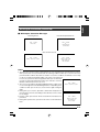
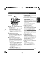
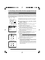
*Illustration with optional lens attachment.
*Illustration mit montiertem optionalem Objektiv.
*Illustration avec objectif optionnel.
®
®
is a registered trademark owned by Victor Company of Japan, Limited.
is a registered trademark in Japan, the U.S.A., the U.K. and many other countries.
© 2004 Victor Company of Japan, Limited
Printed in Japan
LWT0159-001B
Thank you for purchasing this JVC product.
Before operating this unit, please read the
instructions carefully to ensure the best
possible performance.
This instruction manual is made from 100%
recycled paper.
LWT0159-001B
Français
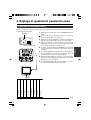
COLOUR VIDEO CAMERA
Deutsch
English
KY-F550
COLOUR VIDEO CAMERA
FARBVIDEOKAMERA
APPAREIL VIDEO EN COULEURS
Thank you for purchasing the JVC KY-F550 Colour Video Camera.
Caractéristiques techniques (suite)
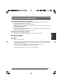
SAFETY PRECAUTIONS
This equipment is in conformity with the provisions and protection requirements of the corresponding European Directives. This equipment is designed for professional video appliances
and can be used in the following environments:
5 Residential (including both of the location type class 1 and 2 found in IEC 1000-2-5)
5 Commercial and light industrial (including, for example, theatres)
5 Urban outdoors (based on the definition of location type class 6 in IEC 1000-2-5)
In order to keep the best performance and furthermore for electromagnetic compatibility we
recommend to use cables not exceeding the following lengths:
Port
Cable
Length
VIDEO OUT
RGB,Y/C,SYNC OUT
LENS
TRIGGER
REMOTE
DV
DC IN
Exclusive Cable
Exclusive Cable
Exclusive Cable
Exclusive Cable
Exclusive Cable
Exclusive Cable
Exclusive Cable
5 meters
2 meters
0.4 meters
5 meters
5 meters
4.5 meters
2 meters
Caution:
5 Where there are strong electromagnetic waves or magnetism, for example near a radio or TV
transmitter, transformer, motor, etc., the picture and sound may be disturbed. In such a case,
please keep the apparatus away from the sources of the disturbance.
: Pendant la sortie RGB, il est possible de choisir de superposer le
signal SYNC sur G.
Sortie DSUB
: Signal RGB, Y/C (avec commutateur à fonctions au choix)
Équilibre des blancs
: AUTO1, AUTO2, FAW, MANUAL, PRESET
Plage compatible: 2300 K - 10000 K
Port DV
: IEEE1394 6 connecteur à broche (un câble avec verrou peut être
utilisé)
Plage de température pendant utilisation : –5 ˚C á 40 ˚C (humidité de 80 % ou moins)
Température admissible en stockage : –20 ˚C á 60 ˚C
Taux d’humidité admissible en stockage : 85 % ou moins
Tension de l’alimentation entrée
: CC 12 V (lors de l’utilisation de AA-P700)
DC 8 V - DC 33 V (lors de l’utilisation d’un câble IEEE 1394)
Consommation électrique
: 12 V
0,7 A
Dimensions
: (W) 67,5 mm x (H) 64 mm x (D) 80,5 mm
(N’inclut pas le port)
Masse
: 380 g (l’unité seule)
Accessoires
: Cordon d’alimentation (8P, 2 m) x 1
Support de montage pour l’appareil x 1
Vis de fixation de support de montate pour la caméra (M2,6 x 6
mm) x 2
Filtre à pince x 2
Pince à fil x 2
Manuel d’instruction x 1
Schéma dimmensionnel (unité: mm)
67,5
66
Note:
TO REDUCE THE RISK OF FIRE OR
ELECTRIC SHOCK, DO NOT EXPOSE
THIS APPLIANCE TO RAIN OR
MOISTURE.
The rating plate (serial number plate) is on the
bottom of the unit.
93,6
80
0,5
MAX4mm
LENS
64
WARNING: NEVER
ATTACH A LENS WHICH
PROTRUDES MORE THAN
4mm SEVERE DAMAGE
WILL RESULT.
SC45550-011
WARNING:
This unit should be used with 12 V DC
only.
CAUTION:
To prevent electric shocks and fire
hazards, do NOT use any other power
source.
SYNC ON G
BARS
1 2 3 4
MENU
CAUTION
SET
AW
To prevent electric shock, do not open the
cabinet. No user serviceable parts inside. Refer
servicing to qualified service personnel.
Risk Class
Type
Moisture Protection
AP/APG Category
Operation Mode
:1
: No Applied Parts
: Ordinary
: No
: Intermit
Les spécifications et le design du produit peuvent être modifiés sans préavis à des fins d’amélioration.
E-2
F-51
Français
These instructions are for KY-F550E.
These instructions are given in three languages: English from page E-2 to E-51
German from page G-2 to G-51
French from page F-2 to F-51
English
SAFETY PRECAUTIONS
JVC Sales Office
1. JVC Professional Europe Ltd.
Ullswater House, Kendal Avenue,
London W3 0XA U.K.
tel: +44(020)8896-6000
2. JVC Professional Europe Ltd. Frankfurt, Germany
Gruener Weg 10, 61169 Friedberg /
Hessen, Germany
tel: +49(06031)6050
3. JVC Professional Europe Ltd. Milano,
Italy
Via Cassanese 224 Palazzo Tiepolo
20090 Segrate-Milano Oltre, Italy
tel: +39(02)380501
4. JVC Professional Europe Ltd. Paris,
France
1 Avenue Eiffel 78422 Carrieres-SurSeine Cedex, France
tel: +33(01)61 04 11 11
5. JVC Professional Europe Ltd.
Barcelona, Spain
Ctra. De Rubi, 88 Ed. Can Castanyer
08190 Sant Cugat del Valles (Barcelona)
Spain
tel: +34(93)565 3220
6. JVC Belgium S.A./N.V.
Rue de la Petite Ile 3, Klein-Eilandstraat,
Bruxelles 1070 Brussel, Belgium
tel: +32(02)529-4211
8. JVC Professional Europe Ltd.
Stockholm, Sweden
Veddestavagen 15,S-175 62 Jarfalla,
Stockholm, Sweden
tel: +46(08)7950400
9. JVC Professional Europe Ltd.
Tonsberg, Norway
PO Box 2012PT, Wirgenes v5, Barkaker
N-3103 Tonberg Norway
tel: +47(333)61600
10. JVC Professional Europe Ltd.
Tastrup,Denmark
Helgeshoej Alle 30 DK-2630 Taastrup,
Denmark
tel: +45(43)509000
11. Spitzer Electronics AG
Muehlemattstrasse 13, CH-4104 Oberwill
Switzerland
tel: +41-61-405-1111
12. Oy Hedpro Ab
Lauttasaarentie 50 FIN-00200 Helsinki
Finland
tel: +358-9-6828244
13. ILVI S.A
62,Piraeus Ave., 183 46 Moschato,
Greek
tel: +30-210-4832855
7. JVC Professional Europe Ltd. Leiden,
Nederland
JVC Plein, De Heyderweg 2, 2314 XZ
Leiden, Nederland
tel: +31(071)545-3333
E-3
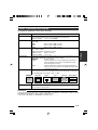
Contents
1. Getting Started
Features ............................................................................................................................................... 6
Points to Note During Use .................................................................................................................... 7
Part Names and Functions ................................................................................................................... 8
Description of Terminals ..................................................................................................................... 12
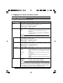
2. Preparation Before Shooting
Connecting Through Digital Output ....................................................................................................
Connecting Through Analogue Output ...............................................................................................
Mounting the Lens ..............................................................................................................................
Connecting the Power Supply ............................................................................................................
Mounting the Camera .........................................................................................................................
Precautions to Prevent Camera From Falling ....................................................................................
14
16
17
18
19
20
3. Setting and Adjustment During Shooting
External Monitor Adjustment .............................................................................................................. 21
White Balance Adjustment ................................................................................................................. 22
White Shading Adjustment ................................................................................................................. 24
4. Various Modes of Shooting
Shooting the Computer Monitor .......................................................................................................... 26
Output of Negative Image ................................................................................................................... 27
White Spot Correction ........................................................................................................................ 28
E-4
Flow of Menu Screens ........................................................................................................................
Setting Procedures .............................................................................................................................
“EXPOSURE” Screen .........................................................................................................................
“ADVANCED EXPOSURE” Screen ....................................................................................................
“WHITE BALANCE” Screen ................................................................................................................
“PROCESS (1/2)” Screen ...................................................................................................................
“PROCESS (2/2)” Screen ...................................................................................................................
“SYSTEM” Screen ..............................................................................................................................
“MATRIX ADJUST” Screen ................................................................................................................
“CAPTURE” Screen ............................................................................................................................
“FILE MANAGE” Screen .....................................................................................................................
30
32
33
35
36
38
40
41
42
43
44
6. Others
Connecting the Remote Control Unit ..................................................................................................
Connecting the IEEE 1394 Cable .......................................................................................................
Connecting the analogue output (D-SUB) Cable ................................................................................
Technical Information .........................................................................................................................
Specifications .....................................................................................................................................
46
48
48
49
50
Notations and Symbols Used in This Manual
Caution
Note
☞
Precautions during operation are stated.
Restrictions of functions and specifications are stated for reference purposes.
Indicates the page and item to refer to.
All product names in this manual are trademarks or registered trademarks of their respective companies.
Marks such as ™, ® and © are not used in this manual.
E-5
English
5. Setting Via the Menu Screen
1. Getting Started
Features
● High quality images can be obtained through high sensitivity of 2000 lx (F11) and high resolution of
horizontal resolution at 800 lines via the newly developed 12-bit DSP.
● Miniature and Lightweight Camera that Employs C Mount
Employment of C mount and 1/3-inch colour separation optics, and compact design through high-density
mounting of the newly developed IC.
● Equipped with D-SUB terminal
Multiple types of output signals which include RGB, Y/C, composite video and composite sync signal
enable this unit to be connected directly to various types of device.
● Equipped with DV Terminal
Digital video signals can be sent to IEEE 1394 compliant devices.
● EBU-compliant Built-in Colour Bars Generator
Colour monitor can be adjusted with ease with the use of EBU colour bars.
● Variable Scan Shutter
Eliminates flicker when shooting screen pictures other than PAL, such as computer screens.
● Slow shutter
Accumulate up to 200 frames of image (approximately 8 seconds). Boosts the brightness of images during shooting for objects with insufficient illumination and little motion.
● Equipped with White Shading Function
Corrects colour shading triggered by optical characteristics.
● Black Stretch/Black Compress Feature
Stretches or compresses the gain of the dark section in an image to adjust the tone of that section.
● Negative
Used for special purposes such as shooting using films.
● AE (Automatic Exposure)
6 selectable modes in the AE area that are useful when there is a difference in brightness between the
object and its surroundings. In addition, exposure settings can also be performed according to shooting
conditions via selection of AE level adjustment or photometry detection.
● Random Trigger Correction Feature
Fast moving objects can be shot with triggering input timing.
● Freeze Correction Feature
Still images (frozen images) of the camera can be captured with triggering input timing.
● Built-in White Spot Correction Feature
● Equipped with Remote Terminal
Supports remote control via the remote control unit (sold separately).
E-6
English
Points to Note During Use
● For important shootings, perform trials in advance to ensure that they are properly recorded.
● We will not compensate for contents lost due to the malfunction of this unit.
䡵 Characteristic CCD Phenomena
● Smear and Blooming
When shooting a bright light source, the CCD may induce white streaks (smear) in the vertical direction
of the light source. When the light source is extremely bright, light of the surroundings may expand
(blooming).
● Aliasing
Note that a jagged effect may occur when shooting striped patterns or lines.
● White spot
Operating this unit under a high temperature may give rise to white spots in the image. Ensure to use
this unit within the specified range (–5˚C to 40˚C). White spots may also appear when set to slow
shutter.
This unit comes with the white spot correction feature that helps to reduce this phenomenon.
☞ Page 28
䡵 Precautions During Handling
● Strong Electromagnetic Waves or Magnetism
When placed near radios or TV transmitters, or transformers and monitors that emit strong magnetism,
noise or colour change may occur in the image. Ensure that this unit is kept away from the above
during use.
● Compatible Lens ☞ Page 17 ‘Mounting the Lens’
Lens mount of this unit makes use of C mount and there are restrictions on the type of lens to be used.
Pay attention to their performance, dimensions, length of the screw portion when lenses other than
those specified are used.
This unit is not equipped with back focus adjustment function. If zoom len is to be used, please use
only lens which are equipped with back focus function.
● Cleaning the Body of this Unit (Turn off the power before cleaning.)
Wipe using a soft cloth.
Do not wipe with thinner or benzene. These may corrode or tarnish the surface.
When it is extremely dirty, wipe using a neutral detergent diluted with water, follow by wiping with a
dry cloth.
● When not in use, turn off the power of the system to reduce power consumption.
● Do not mount unit at locations that emit radiation, X-rays or corrosive gases.
E-7
1. Getting Started (continued)
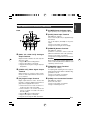
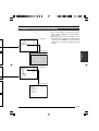
Part Names and Functions
Front / Bottom
4
1
2
3
1 Lens Mount
For mounting lens. Suitable for C mount lens
meant for 3 CCDs.
☞ Page 17 ‘Mounting the Lens’
2 Camera Mounting Bracket
Supplied together with this unit. Mount it to the
top or bottom surface according to the conditions of use. Mount with the fastening screws
for the camera mounting bracket 3.
☞ Page 19 ‘Mounting the Camera’
3 Fastening Screws for Camera
Mounting Bracket
Supplied together with this unit.
(M2.6 x 6 mm, 2 pcs)
Caution
Make sure to use screws that are supplied with
this unit. Use of screws that are 6 mm or longer
in length may give rise to malfunction of the unit.
E-8
4 Camera Mounting Screw Holes (1/
4-20UNC)
Use when mounting this unit to fixer or swivel
bases.
(Use screws that are 7 mm or shorter in length. )
7mm
and
below
English
Part Names and Functions (continued)
Side
5 7 6
5 / BARS
1 2 34
MENU
SET
∞ / AW
8
5 [MENU] Menu Button
Press this button for 1-2 seconds. Menu screen
will be output from the various output terminals.
Press the button for 1-2 seconds again to clear
the menu screen.
☞ Page 32 ‘Setting Procedures’
6 [SET] Set Button
When the menu screen is displayed, use it to
select a submenu or to confirm a selected item
or set value.
☞ Page 32 ‘Setting Procedures’
7 [5/BARS] Up/Colour Bars Button
8 [∞/AW] Down/Auto White button
䡵 When menu screen is displayed
Press these buttons to move between selection
items on the menu screen.
Use the [5] button to move upwards.
Use the [∞] button to move downwards.
Used for altering the set values when an item
is being selected.
䡵 When the menu screen is off
● Press the [AW] button to adjust the white
balance.
☞ Page 22 ‘White Balance Adjustment’
● Press the [AW] button for 1-2 seconds to
adjust the white shading.
☞ Page 24 ‘White Shading Adjustment’
● Press the [BARS] button to switch between
the colour bars output and camera image
output.
Use this button when adjusting the monitor
or when recording colour bars signal.
☞ Page 21 ‘External Monitor Adjustment’
E-9
1. Getting Started (continued)
Part Names and Functions (continued)
9
5 / BARS
1 2 34
MENU
SET
∞/ AW
9 Function Setting Switch
Use for setting the functions of this unit.
Select the switches when the unit is at power
off condition.
● Switch 1 <DV OUTPUT>
[ON] : Compressed DV signal (IEEE1394)
of the camera images will be output.
[OFF] : DV signal will not be output.
Note
If [ON] is selected, the analogue output will
exhibit the same level of horizontal resolution
(about 540 lines) as the DV output.
● Switch 2 <DSUB OUTPUT>
[ON] : Y/C signal will be output.
[OFF] : RGB signal will be output.
E-10
Up:
ON
Down: OFF
1 2 3 4
● Switch 3 <SYNC ON GREEN>
[ON] : Sync signal will be superimposed
onto the Green (G) channel of the
video signal output to the [RGB, Y/
C, SYNC OUT] terminal 0.
[OFF] : Sync signal will not be superimposed.
● Switch 4 <CONTROL MODE>
[ON] : Operate the camera via [DV] terminal (IEEE1394).
Operation via [MENU], [SET], [5/
BARS], [∞/AW] buttons and the remote control unit will not function.
[OFF] : Operate the camera via the buttons
on this unit or the remote control
unit. Operation via [DV] terminal
(IEEE1394) is not functional.
# [POWER] Power Indicator Light
Back
10 11
Lights up when power is supplied to this unit.
$ [DC IN] Power Input Terminal
DV
RGB, Y/C, SYNC OUT
12
LENS
VIDEO OUT
17
POWER
13
DC IN
TRGGER
REMORT
SEE INSTRUCTION MANUAL
16
15
14
0 [RGB, Y/C, SYNC OUT] Analogue
Output Terminal
Output terminal for R/G/B, Y/C and composite
video/sync signal.
☞ Page 10 ‘9 Function Setting Switch’
☞ Page 13 ‘Description of Terminals’
☞ Page 48 ‘Connecting the analogue output (DSUB) Cable’
! [VIDEO OUT] Video Signal Output
Terminal
Output terminal for composite video signals.
Connect to video input terminals such as monitors or switchers.
@ [DV] Digital Output Terminal
Digital output terminal for video. Connect this
terminal to computer’s [IEEE 1394] terminal or
[DV] terminal equipped video devices.
● If this terminal is to be used, set Switch 1 located at the side of this unit to [ON].
● If this terminal is to be used to operate the
camera, set Switch 4 located at the side of
this unit to [ON].
☞ Page 10 ‘9 Function Setting Switch’
☞ Page 13 ‘Description of Terminals’
☞ Page 48 ‘Connecting the IEEE 1394 Cable’
(Mini DIN 8 Pin, Female)
Power of this unit (DC 12 V) is supplied through
this terminal.
Use an AC adaptor (AA-P700) for the power
supply.
☞ Page 12 ‘Description of Terminals’
☞ Page 18 ‘Connecting the Power Supply’
% [REMOTE] Remote Terminal
(Mini DIN 6 Pin, Female)
Terminal for connection to remote control unit
(RM-LP55 or RM-LP57, both sold separately).
☞ Page 12 ‘Description of Terminals’
☞ Page 46 ‘Connecting the Remote Control Unit’
Caution
When using this unit as medical equipment, the
remote control unit (RM-LP55 or RM-LP57 sold
separately) cannot be used.
^ [TRIGGER] Trigger Terminal
(Mini DIN 5 Pin, Female)
For inputting and outputting the various types of
timing signal when Slow Shutter or Random Trigger function is used.
☞ Page 12 ‘Description of Terminals’
☞ Page 49 ‘Technical Information’
& [LENS] Lens Connection Terminal
(Mini DIN 8 Pin, Female)
Connect the lens cable.
☞ Page 12 ‘Description of Terminals’
☞ Page 17 ‘Mounting the Lens’
E-11
English
Part Names and Functions (continued)
1. Getting Started (continued)
Description of Terminals
Power Input Terminal (Mini DIN 8 Pin,
7
Female)
8
6
6
3
2
4
2
5
4
3
5
Pin No.
1
2
3
4
5
6
7
8
Remote Terminal (Mini DIN 6 Pin, Female)
1
1
Signal
NC
GND
NC
NC
GND
+ 12 V Input
NC
+ 12 V Input
Pin No.
1
2
3
4
5
6
Signal
GND
OPERATE(L:ON)
GND
SID2(TX)
SID1(RX)
+ 9 V Output
Trigger Terminal (Mini DIN 5 Pin, Female)
(TCS7858 : Hoshiden)
Lens Connection Terminal (Mini DIN 8
Pin, Female)
5
4
7
8
3
5
2
Pin No.
1
2
3
4
5
6
7
8
E-12
2
3
6
4
1
Signal
LENS TYPE
GND
IRIS CONTROL
+ 12 V Output
SERVO SEL
ZOOM CONTROL
FOCUS CONTROL
Y SIGNAL OUT
1
Pin No.
1
2
3
4
5
Signal
SI Output
TRIG Input
GND
WEN Output
NC
Notes
● Please consult your JVC-authorized dealer on
connection of trigger terminal.
● Ensure to use cables that are shielded.
Suitable Plug: Mini DIN 5 PIN
Analogue Output Terminal (D-sub 9
PIN, Female)
5
1
9
6
Pin No.
1
2
3
4
5
6
7
8
9
Notes
● Cannot be connected to computer monitor.
● Use the function setting switches located at the
side of this unit to select between RGB or Y/C
output.
RGB Output
Pin No.
1
GND
GND
R OUT
G OUT
B OUT
Composite video OUT
Composite sync OUT
GND
GND
2
3
4
5
6
7
8
9
Y/C Output
GND
GND
Y OUT
C OUT
Composite video OUT
Composite Sync OUT
GND
GND
Digital Output Terminal
6
4
2
Pin No.
1
2
3
4
5
6
5
3
1
Signal
VP (POWER)
VG (GND)
TPB TPB +
TPA TPA +
Note
Ensure to attach the supplied clamp filters to the cables connected to the Analogue Signal Output [RGB, Y/
C, SYNC OUT] terminal and Digital Output [DV] terminal in order to reduce unwanted electromagnetic
emissions. ☞ Page 48
E-13
English
Description of Terminals (continued)
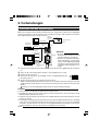
2. Preparation Before Shooting
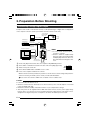
Connecting Through Digital Output
Computer can be used to control this unit remotely, record captured images on digital device or display them
on the computer or monitor. (Please pre-install the exclusive software for this unit.)
‘Connecting the
Power Supply’
(Page 18)
AA-P700
AC ADAPTER AA-P700
POWER
ON
OFF
AC IN
BNC CABLE
Monitor
[VIDEO OUT]
DC IN
VIDEO OUT
LENS
‘Connecting the
IEEE 1394 Cable’
(Page 48)
REMORT
SEE INSTRUCTION MANUAL
POWER
[DV]
RGB, Y/C, SYNC OUT
DV VTR
AC Adapter
[DC IN]
TRGGER
Clamp filter
(accessories)
DV
BR-DV3000
BR-DV6000
Exclusive Software
SET
5 / AW
MENU
5 / BARS
1 2 34
[LENS]
IEEE 1394
Terminal
Computer
1.
2.
3.
4.
5.
‘Mounting the
Lens’ (Page 17)
Notes
● 2 or more of this unit cannot be connected to 1 computer.
● Ensure to attach the supplied clamp
filter to the cable connected to the Digital Output [DV] terminal in order to reduce unwanted electromagnetic emissions.
Connect the [DV] terminal of this unit to the computer’s DV [IEEE1394] terminal.
Set the Switch 1 and Switch 4 located at the side of this unit to [ON] (upper side).
1 2 3 4
Switch on the power of this unit.
ON
OFF
Set the “DV SYSTEM” under “SYSTEM” screen to “JVC”.
Switch 1
Switch 4
Power on the computer and launch the software.
With the exclusive software provided, it is possible to select the various camera settings and operate the
camera for shooting. For details, please consult your JVC-authorized dealer.
Please refer to the software’s HELP menu for details on how it could be used.
Caution
● Perform this when the devices are off.
● When the software has been launched, do not switch on/off the power of the AC adapter or insert and
remove the IEEE 1394 cable.
● Disable the automatic standby or hibernation function of your computer before using it.
● This unit’s power can be supplied from the IEEE 1394 cable. However, use the power supply voltage
between 10.5 V - 15 V if power lens is to be used. Ensure that the supply capacity of the supply source is
adequate in meeting the total power consumptions of both this unit and the power lens used.
E-14
English
Connecting Through Digital Output (continued)
䡵 Specification of Compatible Computer
●
●
●
●
●
●
Pentium 4 2.4 GHz or higher DOS/V, PC/AT compatible machine is recommended.
More than 256 MB RAM is recommended.
Hard disk with a minimum 20 MB of available space.
When video recording is performed, 7200 rpm and above IDE disk (RAID system is recommended).
OS : Windows 2000Pro/XP
Video card : AGP graphic card incorporated with NVIDIA GeForce4MX or GeForceFX chip (GeForce
4MX420, GeForce FX5700)
● DirectX 9.0 or later versions of Enduser Runtime
䡵 Suitable IEEE Host Adapter
● IEEE1394 host adapter card : Matrox Meteor 2-1394, Ratoc REX-CFW3
䡵 Compatible Lens
● Fujinon T14 X 5.5MD
䡵 Option
● AC Adapter : AA-P700
(Using the exclusive software with other graphic cards and under PC environment other than abovementioned might cause a drop in the display performance of the preview window or error might occur.)
For latest information, please check the following homepage.
http: //www.jvc-victor.co.jp/english/pro/prodv/download/index.html
For details, please consult your JVC-authorized dealer.
E-15
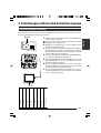
2. Preparation Before Shooting (continued)
Connecting Through Analogue Output
Images taken by this unit can be output to monitor, colour video printer or other devices.
‘Connecting the
Power Supply’
(Page 18)
BNC CABLE
AA-P700
AC ADAPTER AA-P700
POWER
ON
AC IN
OFF
[DC IN]
DC IN
REMORT
SEE INSTRUCTION MANUAL
DV
AC Adapter
[REMOTE]
[TRIGGER]
MENU
SET
TRGGER
VIDEO OUT
LENS
[RGB, Y/C, SYNC OUT]
RGB, Y/C, SYNC OUT
Clamp filter
(accessories)
Monitor
POWER
[VIDEO OUT]
VC-451-2
CP700DSA
SHEET
PAPER
]
PAPER FEED & CUT
ALARM
COPY
MITSUBISHI
ONLINE
DATA
POWER
OPEN
Colour Video Printer etc.
R
G/Y
B/C
SYNC
VBS
1.
Connect device such as the Colour Video Printer
to this unit’s [RGB, Y/C, SYNC OUT] terminal.
2.
Set the switches located at the side of this unit.
● Setting Switch 2
Set this switch to [ON] (upper side) for Y/C
output.
Set this switch to [OFF] (lower side) for RGB
output.
● Setting Switch 3
Set this switch to [ON] (upper side) if sync signal is to be superimposed onto the Green (G)
channel of the video signal.
☞ Page 10 ‘9 Function Setting Switch’
Example: During RGB output
ON
OFF
1 2 3 4
Switch 2
3.
Switch 3
Switch on the power of this unit.
E-16
REMOTE
CONTROL
UNIT
RM-LP55
RM-LP57
Microscope
Adapter
Trigger Switch
Caution
● Perform this when the devices are off.
● Use the 1/3-inch, C mount adapter for the microscope adapter.
Notes
● Connect a switch between PIN 2 (TRIG) and PIN
3 (GND) of the [TRIGGER] terminal. If this switch
is set to [ON], a trigger will freeze the input image
to the camera and capturing of images synchronized with the trigger is possible.
● Ensure to attach the supplied clamp filter to the
cable connected to the Analog Signal Output
[RGB, Y/C, SYNC OUT] terminal in order to reduce unwanted electromagnetic emissions.
☞ Page 48
English
Mounting the Lens
Follow the procedures below when mounting the auto iris lens.
Refer to the ‘instruction manual’ for the lens as well.
1.
Camera Head
Threaded
Portion
Mount Fastening Ring
2. Lock
(Male)
Align and press the threaded portion of the lens
mount against the threaded portion of this unit’s
lens mount and turn the mount fastening ring
clockwise slowly until the lens is firmly attached
to this unit.
Note
Lens
1.
Compatible Zoom Lens
T14 x 5.5MD
To change the position of the lens rotation,
1 First, loosen the mount fastening ring by rotating it anti-clockwise by 1/4 turn as viewed from
the lens side.
2 Turn the lens gently, adjust the position and
tighten the mount fastening ring again.
2.
Caution
● Perform this when the unit is off. Connecting with
the power on may give rise to malfunction of the
unit.
● When removing the lens mount cap, ensure that
no foreign substances are inside the mount.
● Lenses are not supplied with this unit. Depending
on the lens being used, this unit may be damaged.
As such, ensure to use lens that are 4 mm or below, reference from the lens mount.
Plug the lens cable into the [LENS] terminal at
the back of the unit and ensure that it is locked.
Iris control is carried out from this unit.
䡵 Setting the “IRIS MODE” of the “EXPOSURE”
Screen
☞ Page 33
● If auto iris lens is to be used and iris control is to
be automatically carried out, set to “AUTO”.
● If auto iris lens is to be used and iris control is to
be fine-tuned, set to “MANUAL”.
4 mm and below
E-17
2. Preparation Before Shooting (continued)
Connecting the Power Supply
Connect the [DC IN] terminal at the back of this unit to the [TO CAMERA] terminal of the AC adaptor (AAP700) using the power cable supplied (2 m).
DV
RGB, Y/C, SYNC OUT
AC Adapter
AA-P700
DC 12V=OUTPUT
VIDEO OUTPUT
AC 230 V
VIDEO OUT
LENS
POWER
S(Y/C) OUTPUT
EITHER
OUTPUT
MAX 1.25A
TO CAMERA
DC IN
TRGGER
SEE INSTRUCTION
MANUAL
REMORT
SEE INSTRUCTION MANUAL
AC IN
[TO CAMERA] Terminal
White Marking
Connect the end with
white marking to the
AC adaptor.
POWER
DC IN
[DC IN]
Terminal
Power Cable (2 m)
(accessories)
● Insert plug fully, turn ring and ensure
that it is fastened.
Ring
Plug
Notes
● Ensure to make use of AA-P700 for the power supply.
When connecting, ensure that power switch of AA-P700 is turned OFF.
Connecting with the power on may give rise to malfunction of the equipment.
● When power is supplied, it takes several seconds before this unit is operable.
When the “SHUTTER” item under “EXPOSURE” screen is set to “SLOW”, it might take even longer time.
● Allow a 10 second interval after switching off the power before turning on again. If the power switch is
turned ON and OFF too soon, malfunctioning such as startup failure may occur.
Caution
In case of medical use
Make sure to use the specified AC Adapter.
UK Market ................................... AA-P700EK
Other European Market ............. AA-P700EG
E-18
English
Mounting the Camera
<Procedures for mounting camera mounting bracket>
Use the supplied camera mounting bracket and 2
fastening screws of the camera mounting bracket to
mount it to the top or bottom surface.
Caution
Make sure to use screws that are supplied with this
unit. Use of screws that are 6 mm or longer in length
may give rise to malfunction of the unit.
<Mounting Procedures>
Anti-rotation Hole
● To mount this unit, make use of the screw holes
for mounting the camera on the camera mounting
bracket.
● When mounting this unit, make use of the antirotation hole to prevent it from falling.
Camera Mounting Bracket
Screw Hole for Mounting Camera
E-19
2. Preparation Before Shooting (continued)
Precautions to Prevent Camera From Falling
Safety cable to Prevent
Falling of Equipment
4 mm
1-1.5 mm
Camera Head
Caution
● Special attention is required when mounting to the wall or ceiling. Get a contractor
to perform the work and avoid doing it on your own. Unit may fall off and cause
injuries or accidents.
● Mount the unit to a secure place using safety cable to prevent it from falling. To
mount, make use of the bracket fastening screw holes on the face without the camera mounting bracket. (M2.6 x 4 mm) Pay attention also to the length of the cable.
● Strength of cable to prevent falling of unit shall be at least 10 times greater than the
total mass of the camera and lens.
E-20
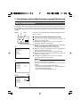
External Monitor Adjustment
Display the built-in colour bars signal at the camera on the monitor to perform colour/contrast/brightness
adjustment.
1. Connect the colour video monitor to the [VIDEO OUT] of this
2. [BARS]
unit.
Make sure that the Switch 4 located at the side of this unit is
set to [OFF] (lower side).
5 / BARS
1 2 34
MENU
2.
Press the [BARS] button to output the colour bars signal (EBUcompliant colour bars).
3.
With the colour bars displayed, turn [BLUE CHECK] at the
monitor to ON. Screen turns into a monochrome of blue and
colour bars appear as blue stripes.
4.
Turn the [CHROMA] adjustment knob on the monitor and
adjust colour bars 1 and 7 to the same brightness level.
5.
With [BLUE CHECK] in the ON mode, turn the [PHASE] adjustment knob on the monitor to adjust colour bars 3 and 5
to the same brightness level.
6.
If brightness of colour bars 1 and 7 vary upon [PHASE] adjustment, repeat chroma adjustment as in step 4..
7.
Turn [BLUE CHECK] at the monitor to OFF and return to the
normal screen (R. G. B are all displayed).
SET
∞/ AW
Switch 4: [OFF]
DV
RGB, Y/C, SYNC OUT
LENS
1.
VIDEO OUT
POWER
DC IN
TRGGER
REMORT
SEE INSTRUCTION MANUAL
1 2 3 4 5
Black
Blue
Red
Magenta
Green
Cyan
Yellow
White
3.~7.
6 7 8
E-21
English
3. Setting and Adjustment During Shooting
3. Setting and Adjustment During Shooting (continued)
White Balance Adjustment
Colour of light (colour temperature) may vary with light sources. When light source for illumination of object
is changed, adjust white balance (AUTO WHITE) again. Do not place strong reflectors such as metals near
the object. This may cause error in achieving white balance.
[MENU]
[SET]
[5]
White balance adjustment includes Auto White, Full-time Auto White
(FAW), manual and preset.
5 / BARS
1 2 34
MENU
SET
∞/ AW
䡵 Setting procedures for Auto White (“AUTO1”,
“AUTO2”)
Make sure that the Switch 4 located at the side of this unit is set to
[OFF] (lower side).
[∞] Switch 4: [OFF]
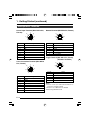
Item
Set Value
- - - WHI TE BA LANCE - - WH I TE BA LANCE
AUTO1
0
L EVE L ( R )
0
L EVE L ( B )
S H AD I NG
PRESE T
L EVE L ( R )
-----L EVE L ( G )
-----L EVE L ( B )
-----PAGE BACK
“WHITE BALANCE” Screen
Auto White Operation Area
1.
Press the [MENU] button for 1-2 seconds.
The “MENU” screen will be displayed.
2.
Use the [5/∞] buttons to select “WHITE BALANCE..”, then press
the [SET] button.
The “WHITE BALANCE” screen will be displayed.
3.
Use the [5/∞] buttons to select “WHITE BALANCE”, then press
the [SET] button.
The set value displayed will start to blink.
4.
Use the [5/∞] buttons to select “AUTO1” or “AUTO2”, then press
the [SET] button.
5.
Press the [MENU] button for 1-2 seconds.
The normal screen will be displayed.
Note
Upon returning to the normal screen, place a white object with the
same illumination conditions as the object, zoom in to the white
portion at the centre of the screen (above 80% within the area).
AUTO W H I T E 1
O PERA T I O N
6.
Auto White Operation Activated
AUTO W H I T E 1
OK (3200K)
Auto White Operation Ends
E-22
Press the [AW](Auto White) button.
● When auto white is activated, the auto white operation area
and “AUTO WHITE1,2 OPERATION” are displayed on the monitor.
● When white balance is achieved, a rough colour temperature
as well as “AUTO WHITE1,2 OK” will be displayed for about 3
seconds before returning to the normal screen.
English
White Balance Adjustment (continued)
Error Display
AUT O WH ITE 1
N G : OB J ECT
Object Error
AUT O WH ITE 1
ERRO R : LO W L I GH T
Insufficient Illumination
When auto white adjustment is not correctly ended, the following
message will be displayed for about 3 seconds.
● “NG : OBJECT” (Object Error)
Displayed when there is little white colour in the object or when
colour temperature is not appropriate.
Change to a white object and perform procedures again to
achieve white balance.
● “ERROR : LOW LIGHT” (Insufficient Illumination)
Displayed when the illumination is too dark. Open the lens aperture or brighten the illumination and perform procedures again
to achieve white balance.
● “ERROR : OVER LIGHT” (Excessive Illumination)
Displayed when the illumination is too bright. Close the lens
aperture or darken the illumination and perform procedures
again to achieve white balance.
Caution
AUT O WH ITE 1
ERRO R : OV E R L I G HT
Excessive Illumination
● When this unit is set as below, auto white cannot be activated.
• When the “SHUTTER” item under “EXPOSURE” screen is
set to “SLOW”.
• When the “MODE” item under “CAPTURE” screen is set to
“RANDOM TRG”.
• When auto white shading is being activated.
● If white balance is to be adjusted when processing frozen image, return to the normal screen before activating auto white.
䡵 Full-time Auto White (FAW) Function
Automatic adjustment of white balance according to different illumination conditions.
This mode is useful when there is no time to readjust white balance or when camera is frequently moved
to locations with different illumination conditions.
● However, white balance cannot be properly achieved in cases that are beyond the adjustable range
of the full-time auto white function, such as when there is only one colour or little white colour in the
object.
● Precision of FAW deteriorates when compared with auto white balance.
● When power is turned on in the FAW mode, it takes about 10 seconds for the FAW automatic adjustment to end.
E-23
3. Setting and Adjustment During Shooting (continued)
White Shading Adjustment
There are cases when white balance is achieved for the centre of the screen but not for the upper and lower
ends, hence causing other colours to appear with green or magenta. This is brought about by the lens
characteristics. The process of rectifying this is known as white shading.
[MENU]
[SET]
[5]
Perform the following setting upon adjusting white balance.
☞ Page 22
䡵 Auto White Shading Adjustment
5 / BARS
Make sure that the Switch 4 located at the side of this unit is set to
[OFF] (lower side).
1 2 34
MENU
SET
∞/ AW
1.
Press the [MENU] button for 1-2 seconds.
The “MENU” screen will be displayed.
2.
Use the [5/∞] buttons to select “WHITE BALANCE..”, then press
the [SET] button.
The “WHITE BALANCE” screen will be displayed.
3.
Use the [5/∞] buttons to select “SHADING”, then press the [SET]
button.
The set value starts blinking and adjustment is possible.
4.
Use the [5/∞] buttons to set value to “AUTO”, then press the
[SET] button.
5.
Press the [MENU] button for 1-2 seconds.
The normal screen will be displayed.
[∞] Switch 4: [OFF]
1.
---
MENU
---
EXPOSURE . .
WH I TE BA L ANCE . .
PROCESS . .
SYSTEM . .
CAPTURE . .
F I L E MANAGE . .
EX I T
“MENU” Screen
2.
Note
- - - WHI TE BA LANCE - - MANUA L
WH I TE BA LANCE
0
L EVE L ( R )
0
L EVE L ( B )
S H AD I NG
PRESE T
L EVE L ( R )
-----L EVE L ( G )
-----L EVE L ( B )
-----PAGE BACK
“WHITE BALANCE” Screen
3. 4.
Blinking
- - - WHI TE BA LANCE - - MANUA L
WH I TE BA LANCE
0
L EVE L ( R )
0
L EVE L ( B )
S H AD I NG
AUTO
-----L EVE L ( R )
-----L EVE L ( G )
-----L EVE L ( B )
PAGE BACK
E-24
After returning to normal screen, shoot a white object to the entire
screen.
In addition, pay attention to the followings for proper adjustment.
● Use an object which is evenly white.
● Adjust so that the object has an even brightness.
● Set the lens aperture from F4.
6.
AUT O SHADING
OPERATION
Press the [AW] (Auto White) button for 1-2 seconds.
● When auto shading is activated, “AUTO SHADING
OPERATION” is displayed on the monitor.
● When auto shading adjustment is achieved, “AUTO
SHADING OK” will be displayed for about 3 seconds before
returning to the normal screen.
Caution
AUT O
SHADING
OK
● When this unit is set as below, auto white shading cannot be
activated.
• When the “SHUTTER” item under “EXPOSURE” screen is
set to “SLOW”.
• When the “MODE” item under “CAPTURE” screen is set to
“RANDOM TRG”.
• When auto white is being activated.
● If white shading is to be adjusted when processing frozen image, return to the normal screen before activating auto white
shading.
7.
AUT O SHADING
N G : OB J ECT
Upon completing auto white shading adjustment, perform
white balance adjustment again.
☞ Page 22 ‘White Balance Adjustment’
Error Display
Object Error
AUT O SHADING
ERRO R : LO W L I GH T
Insufficient Illumination
When auto white shading adjustment is not correctly ended, the
following message will be displayed for about 3 seconds.
● “NG : OBJECT” (Object Error)
Displayed when the object is not evenly white.
Change to an evenly white object and perform procedures again
to achieve auto white shading.
● “ERROR : LOW LIGHT” (Insufficient Illumination)
Displayed when the illumination is too dark. Open the lens aperture or brighten the illumination and perform the procedures
again to achieve auto white shading.
● “ERROR : OVER LIGHT” (Excessive Illumination)
Displayed when the illumination is too bright. Close the lens
aperture or darken the illumination and perform the procedures
again to achieve auto white shading.
AUT O SHADING
ERRO R : OVER L I G H T
Excessive Illumination
E-25
English
White Shading Adjustment (continued)
4. Various Modes of Shooting
Shooting the Computer Monitor
When shooting images of computer monitors or displays, horizontal bands will appear on the screen. To
eliminate the bands, it will be necessary to align the shutter speed with the scanning frequency of the
monitor.
Make sure that the Switch 4 located at the side of this unit is
set to [OFF] (lower side).
1.
Press the [MENU] button for 1-2 seconds.
The “MENU” screen will be displayed.
2.
Use the [5/∞] buttons to select “EXPOSURE..”, then press
the [SET] button.
3.
Use the [5/∞] buttons to select “SHUTTER”, then press the
[SET] button.
The set value starts blinking and adjustment is possible.
4.
Use the [5/∞] buttons to set value to “V. SCAN”, then press
the [SET] button.
5.
Use the [5/∞] buttons to select “LEVEL”, then press the [SET]
button.
6.
Use the [5/∞] buttons to adjust the shutter speed. Pay attention to the screen,
If black bands are visible : use the [∞] button to lower the
shutter speed
If white bands are visible : use the [5] button to increase the
shutter speed
7.
When bands are decreased to the minimum, press the [SET]
button. This will be recorded in the memory of the unit.
8.
Press the [MENU] button for 1-2 seconds.
The normal screen will be displayed.
Band
Computer Monitor
3. 4.
- - - EXPOSURE - - I R I S MODE
MA NU A L L EVE L
GA I N
L EVE L
SHUT TER
L EVE L
ADVANCED EXPOSURE .
PAGE BACK
AUTO
-----ST EP
0dB
ST EP
NORMAL
.
“EXPOSURE” Screen
5. 6.
- - - EXPOSURE - - I R I S MODE
MA NU A L L EVE L
GA I N
L EVE L
SHUT TER
L EVE L
ADVANCED EXPOSURE .
PAGE BACK
AUTO
-----ST EP
0dB
V. SCAN
1 / 5 0s
.
Note
Vertical scanning frequency may vary with computer types and there are cases when bands may not be fully
eliminated. In addition, frequency may also differ depending on the software used.
E-26
It is possible to convert video signals from the various output terminals of this unit into negative images.
[MENU]
[SET]
[5]
5 / BARS
1 2 34
MENU
SET
Make sure that the Switch 4 located at the side of this unit is
set to [OFF] (lower side).
1.
Press the [MENU] button for 1-2 seconds.
The “MENU” screen will be displayed.
2.
Use the [5/∞] buttons to select “SYSTEM..”, then press the
[SET] button.
The “SYSTEM” screen will be displayed.
3.
Use the [5/∞] buttons to select “NEGATIVE”, then press the
[SET] button.
The set value starts blinking and adjustment is possible.
4.
Use the [5/∞] buttons to set value to “ON”, then press the
[SET] button.
This will be recorded in the memory of this unit.
Output image will be converted to negative images.
5.
Press the [MENU] button for 1-2 seconds.
The normal screen will be displayed.
∞/ AW
[∞] Switch 4: [OFF]
2. 3.
Blinking
- - - SYSTEM - - -
NEGA T I VE
P I XE L COMPEN
DV SYSTEM
PAGE BACK
OF F
CANCE L
JVC
“SYSTEM” Screen
4. 5.
- - - SYSTEM - - NEGA T I VE
P I XE L COMPEN
DV SYSTEM
PAGE BACK
ON
CANCE L
JVC
“SYSTEM” Screen
E-27
English
Output of Negative Image
4. Various Modes of Shooting (continued)
White Spot Correction
As a peculiar common characteristic of CCD, white spots may appear on the screen when it is operated
under high temperature or when shutter speed is prolonged during use.
This unit comes with a white spot correction feature to reduce this phenomenon.
How To Use
䡵 Detection of White Spots
The quantity and size of white spots differ with the temperature and shutter speed during use. Before
using the white spot correction feature, it will thus be necessary to detect the position of the white spots
under the conditions of use.
[MENU]
Preparation
[SET]
[5]
5 / BARS
1 2 34
MENU
SET
∞/ AW
[∞] Switch 4: [OFF]
2. 3.
Blinking
● Set the conditions of use (ambient temperature, shutter speed,
etc.) in this unit.
● When Random Trigger or Slow Shutter function has been set,
White Spot Correction cannot be activated. Change to other
settings.
● Turn on the power of the camera and leave it on for at least 2 hours.
● Close the lens iris to ensure that no light enters the CCD. (When
using Galvano lens, use lens cap to prevent light from entering
the CCD.)
Operation
Make sure that the Switch 4 located at the side of this unit is
set to [OFF] (lower side).
- - - SYSTEM - - NEGA T I VE
P I XE L COMPEN
DV SYSTEM
PAGE BACK
OF F
CANCE L
JVC
“SYSTEM” Screen
4. 5.
- - - SYSTEM
NEGA T I VE
P I XE L COMPEN
DV SYSTEM
PAGE BACK
Press the [MENU] button for 1-2 seconds.
The “MENU” screen will be displayed.
2.
Use the [5/∞] buttons to select “SYSTEM..”, then press the
[SET] button.
The “SYSTEM” screen will be displayed.
3.
Use the [5/∞] buttons to select “PIXEL COMPEN”, then press
the [SET] button.
The “CANCEL” value starts blinking and adjustment is possible.
4.
Use the [5/∞] buttons to select “EXECUTE” and press the
[SET] button to start the white spot detection.
Detection process may take a few minutes to complete.
5.
Upon completing detection, “Detection Completed” screen will
be displayed.
6.
Turn on the power again.
Allow a 10 seconds interval after switching off the power before turning on again.
When power is turned on, white spots will be corrected.
Blinking
-- OF F
EXECUTE
JVC
“SYSTEM” Screen
E-28
1.
English
White Spot Correction (continued)
䡵 White Spots Correction Messages
Detecting Screen
PIXEL
Detection Completed Screen
PIXEL
COMPEN
EXE CUT I NG
COMPEN
OK
TURN POWER OFF
AND ON AGAIN.
Detection Error Screen
PIXEL COMPEN
ERROR : LENS NOT CLOSED?
COMPEN
PIXEL
ERROR : COUNT OVER
TURN POWER OFF
AND ON AGAIN.
Notes
● The white spot correction feature of this unit does not correct all white spots. Detection and correction of
white spots by this unit is performed under the following conditions. White spot correction will not be
performed under conditions beyond those stated. In cases where conditions are fulfilled, correction may
not be successfully performed depending on the nature of the white spots.
In such case, perform the detection again until white spots are detected.
Consult your JVC authorized dealer if white spots cannot be corrected.
Quantity of Detection/Correction: 32 or less
PIXEL COMPEN
● The screen on the right may be displayed during detection of white spots
ERROR : LENS NOT CLOSED?
in cases when light enters the CCD during detection or depending on the
condition of white spots. In this case, check if there is light entering the
CCD.
● During white spot correction, pixel data is obtained via interpolation of
pixel information from the surroundings. Thus data may not be accurate
for fine images.
● Results of white spot detection will be stored until the next detection is
PIXEL COMPEN
performed.
ERROR : COUNT OVER
TURN POWER OFF
● During white spot detection, operation via the remote control will be disaAND ON AGAIN.
bled.
E-29
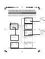
5. Setting Via the Menu Screen
Flow of Menu Screens
The menu screen is made up of multiple layers of menu screens as illustrated in the diagram below.
Select the menu screen for setting at the MAIN MENU screen according to function and usage, and perform
setting accordingly.
- - - EXPOSURE - - I R I S MODE
MA NU A L L EVE L
GA I N
L EVE L
SHUT TER
L EVE L
ADVANCED EXPOSURE .
PAGE BACK
AUTO
-----ST E P
0d B
STEP
NORMAL
☞ Page 33
- - - ADVANCED E
A LC L I M I T
EE I L I M I T
AE L EV E L
AE DETEC T
AE ARE A . .
PAGE BACK
.
Cursor
MAIN MENU
---
MENU
---
- - - WHI TE BA LANCE - - WH I TE BA LANCE
AUTO1
L EVE L ( R )
0
L EVE L ( B )
0
S H AD I NG
PRESET
L EVE L ( R )
-----L EVE L ( G )
-----L EVE L ( B )
-----PAGE BACK
EXPOSURE . .
WH I TE BA L ANCE . .
PROCESS . .
SYSTEM . .
CAPTURE . .
F I L E MANAGE . .
EX I T
- - - PROCESS ( 1 / 2 ) - - M AS TER B L ACK
0
DETA I L
ON
LEVEL
0
0
V / H B A L A N CE
FR EQUE NC Y
LOW
V. RESOLUT I ON
N OR M AL
WH I TE C L I P
1 0 8%
KNEE
A UT O
LEVEL
-----NEXT PAGE . .
PAGE BACK
Normal Screen
- - - SYSTEM
NEGA T I VE
P I XE L COMPEN
DV SYSTEM
PAGE BACK
-- OF F
CANCE L
JVC
☞ Page 36
☞ Page 38
☞ Page 41
☞ Page 44
- - - F I LE MANAGE - - LOAD F I LE
LOAD
STORE F I LE
STORE
RESET F I LE
RESE T
PAGE BACK
E-30
A
CANCE L
A
CANCE L
A
CANCE L
- - - CAPTURE - - MODE
FREE ZE
FREE ZE T RG
ALTERNATE
I MAGE T YPE
F I ELD
RANDOM SHUT.
1 / 50
PAGE BACK
☞ Page 43
- - - PROCES
COLOR MATR I X
AD J UST . .
GAMMA
L EVEL
BL ACK
FL ARE
MASTER
F L ARE ( R )
F L ARE ( B )
PAGE BACK
AL
☞ Page 35
- - - ADVANCED EXPOSURE - - A LC L I M I T
EE I L I M I T
AE L EV E L
AE DETEC T
AE ARE A . .
PAGE BACK
+ 1 8 dB
1 / 200
0
NORMAL
● At any displayed screen, normal screen will be
restored if [MENU] button is pressed for 1-2 seconds.
● When the remote control is connected, items that
can be operated via the remote control will be displayed as “REMOTE” on the menu screen. Operation of these items via the camera unit will be
disabled.
☞ Page 35
NORMAL
- - - PROCESS ( 2 / 2 ) - - COLOR MATR I X
S T A N DARD
AD J UST . .
M AN U AL
GAMMA
0
L EVEL
N OR M AL
BL ACK
FL ARE
ON
0
MASTER
F L ARE ( R )
0
0
F L ARE ( B )
PAGE BACK
☞ Page 40
☞ Page 42
- - - MAT R I X A D J UST - - R GA I N
R ROT A T I ON
G GA I N
G ROT A T I ON
B GA I N
B ROT A T I ON
PAGE BACK
0
0
0
0
0
0
E
E-31
English
Flow of Menu Screens (continued)
5. Setting Via the Menu Screen (continued)
Setting Procedures
The various functions of this unit can be set using the menu screen. Settings will be stored in the memory of
this unit and will remain recorded when the power is turned off.
[MENU]
[SET]
[5]
1.
Set the Switch 4 located at the side of this unit to [OFF] (lower
side).
5/ BARS
ON
OFF
1 2 34
MENU
SET
Switch 4
∞/ AW
[∞]
Switch 4: [OFF]
3.
---
MENU
2.
3.
Switch on the power to this unit.
4.
Use the [5/∞] buttons to select an item, followed by pressing
the [SET] button. The submenu screen will be displayed.
5.
For the submenu screens, similarly, use the [5/∞] buttons to
select an item, then press the [SET] button.
The set value starts blinking and adjustment is possible.
6.
Use the [5/∞] buttons to alter the set value, followed by pressing the [SET] button. Set value will be confirmed and recorded
in the memory of this unit.
---
EXPOSURE . .
WH I TE BA L ANCE . .
PROCESS . .
SYSTEM . .
CAPTURE . .
F I L E MANAGE . .
EX I T
If there is a huge difference in the magnitude of value to be
set, press and hold the [5/∞] buttons to speed up the change.
Use this when making a significant change to the set value.
4.
- - - EXPOSURE - - I R I S MODE
MA NU A L L EVE L
GA I N
L EVE L
SHUT TER
L EVE L
ADVANCED EXPOSURE .
PAGE BACK
AUTO
-----ST EP
0dB
ST EP
NORMAL
.
“EXPOSURE” Screen
(Example)
(Submenu Screen)
Press the [MENU] button for 1-2 seconds.
The “MENU” screen will be displayed.
Note
“MENU” Screen
E-32
1 2 3 4
7.
Press the [MENU] button for 1-2 seconds.
The normal screen will be displayed.
English
“EXPOSURE” Screen
Settings in bold are factory settings
Item
“IRIS MODE”
“MANUAL
LEVEL”
“GAIN”
“LEVEL”
“SHUTTER”
Function/Variable Values
Switch according to the lens in use.
“AUTO”
: When using auto iris lens.
“MANUAL”
: When using manual iris lens.
For setting the iris level when “IRIS MODE” is set to “MANUAL”. (Set the iris mode
switch on the lens side to “AUTO”.)
Increase value : Opens the iris.
Decrease value : Closes iris.
{Variable Values : 0 - 128 - 255}
Note
When “IRIS MODE” is set to “AUTO”, “MANUAL LEVEL” item selection will be
disabled. (Displayed as “- - - - - -”)
For switching the electric sensitivity mode.
“STEP”
: Gain boost level can be altered using the “LEVEL” item.
“V. GAIN”
: Gain boost level can be fine-tuned using the ”LEVEL“ item.
“ALC”
: Alters gain boost level automatically according to the
brightness.
Set the maximum value at the “ALC LIMIT” item. ☞ Page 35
Gain boost level can be altered when gain boost mode is set as “STEP” or “V.
GAIN”.
{Variable “STEP” Values: –3, 0, +3, +6, +9, +12, +15, +18dB, LOLUX}
{Variable “V. GAIN” Values: –3 - 0 - 18dB 0.2dB Step}
Note
When “GAIN” is set to “ALC”, “LEVEL” item selection will be disabled.
(Displayed as “- - - - - -”)
For switching the shutter mode.
“STEP”
: Shutter speed can be altered using the “LEVEL” item.
“V. SCAN”
: Align scan speed of monitor to eliminate horizontal lines that
appear when shooting the computer monitor. Shutter can be
fine-tuned using the “LEVEL” item.
☞ Page 26 ‘Shooting the Computer Monitor’
E-33
5. Setting Via the Menu Screen (continued)
“EXPOSURE” Screen (continued)
Settings in bold are factory settings
Item
“SHUTTER”
“EEI”
“SLOW”
“LEVEL”
“ADVANCED
EXPOSURE”
“PAGE BACK”
E-34
Function/Variable Values
: Adjusts shutter speed automatically according to brightness
of object. (Maximum value: 1/960)
Set the maximum value at the “EEI LIMIT” item. ☞ Page 35
: Slow shutter speed can be fine-tuned using the “LEVEL”
item.
Accumulates up to 200 frames of image (approximately 8
seconds). Boosts the brightness of images during shooting
for objects with insufficient illumination and little motion.
Notes
● When setting to “SLOW”, set the “GAIN” item to other than “ALC”.
● When the setting is “SLOW”, the screen refresh interval will be longer if the
frame rate is increased. In addition, the change of menu setting is reflected
after the screen is refreshed.
{Variable “STEP” Values : 1/6.25, 1/12.5, 1/25, NORMAL (1/50), 1/120, 1/250,
1/500, 1/1000, 1/2000, 1/4000, 1/10000}
{“V. SCAN” variable
: Approx. 1/50 - approx. 1/10000}
{Variable Values
: 1 frame - 200 frame}
Notes
● When “SHUTTER” is set to “EEI”, “LEVEL” item selection will be disabled. (Displayed as “- - - - - -”)
● When the “SHUTTER” item is set to “SLOW” or when the “MODE” item under
“CAPTURE” screen is set to “RANDOM TRG”, the operation of auto white, auto
iris, “ALC” and “FAW” will be as follows:
Auto White : Startup of auto white is disabled.
Auto Iris : Change to “MANUAL”.
“ALC”
: Change to “STEP (0 dB)”.
“FAW”
: Change to “AUTO1”.
● There will be insufficient light intensity if the shutter speed is increased and
adjustment of lens iris and gain will be necessary. Attention shall be paid to the
picture quality when gain is increased as this increases the sensitivity and screen
may become grainy as a result.
Invokes the “ADVANCED EXPOSURE” screen.
☞ Page 35 ‘“ADVANCED EXPOSURE” Screen’
Press the [SET] button to return to the “MENU” screen when cursor is at this
position.
English
“ADVANCED EXPOSURE” Screen
Settings in bold are factory settings
Item
“ALC LIMIT”
“EEI LIMIT”
“AE LEVEL”
“AE DETECT”
“AE AREA..”
Function/Variable Values
For setting the maximum “ALC” value that triggers automatic switching of gain
boost level according to the brightness.
{Variable Values : +9, +12, +15, +18 dB}
For setting the maximum shutter speed when shutter mode is set to “EEI”.
1/200
: Set as 1/200 seconds.
1/400
: Set as 1/400 seconds.
1/800
: Set as 1/800 seconds.
For adjusting the image level when using auto iris, “ALC” or “EEI”.
Increase value : Increases level.
Decrease value : Decreases level.
{Variable Values: –5 - 0 - +5}
Selects the detection method of the detection area when auto iris, “ALC” or “EEI”
is used.
“NORMAL”
: Normal Position
“PEAK”
: Detects the maximum brightness value (peak level) to
enhance visibility of objects with high luminance.
“AVG”
: Detects the average brightness value (average) to enhance
visibility of objects with high luminance.
Invokes the “AE AREA” screen.
For selecting the detection area of the image level when using auto iris, “ALC” or
“EEI”.
“NORMAL”
“SQUARE”
Detection Area
Detection Area
“SPOT”
“FULL”
“CIRCLE”
“RECTANGLE”
Detection Area
Detection Area
Detection Area
Detection Area
“PAGE BACK”
Press the [SET] button to return to the “EXPOSURE” screen when cursor is at this
position.
Note
The “AE LEVEL”, “AE DETECT” and “AE AREA” items cannot be selected when operation of auto iris, “ALC”
and “EEI” are set as disabled.
The “AE LEVEL” and “AE DETECT” items are displayed as “- - - - - -”.
E-35
5. Setting Via the Menu Screen (continued)
“WHITE BALANCE” Screen
Settings in bold are factory settings
Item
“WHITE
BALANCE”
“LEVEL (R)”
“LEVEL (B)”
Function/Variable Values
For setting the white balance mode.
“AUTO 1”
: Set to this to enable automatic adjustment of white balance.
“AUTO 2”
: Equipped with 2 modes (“AUTO 1” and “AUTO 2”).
☞ Page 22 ‘White Balance Adjustment’
“LEVEL (R)” and “LEVEL (B)” items allow fine-tuning of white
colour upon achieving white balance.
“FAW”
: Automatic adjustment of white balance according to different
illumination conditions.
“MANUAL”
: Manual adjustment of white balance.
Can be altered using the “LEVEL (R)” and “LEVEL (B)” items.
“PRESET”
: Fixes white balance at 3200 K.
For adjusting the reddishness of white balance when “WHITE BALANCE” is set to
“AUTO” or “MANUAL”.
Increase value : Increases reddishness on screen.
Decrease value : Decreases reddishness on screen.
{Variable Values During “AUTO”: –32 - 0 - +31}
{Variable Values During “MANUAL”: 0 - 128 - 255}
For adjusting the bluishness of white balance when “WHITE BALANCE” is set to
“AUTO” or “MANUAL”.
Increase value : Increases bluishness on screen.
Decrease value : Decreases bluishness on screen.
{Variable Values During “AUTO”: –32 - 0 - +31}
{Variable Values During “MANUAL”: 0 - 128 - 255}
Notes
● Selection of “LEVEL (R)” and “LEVEL (B)” items is disabled when the “WHITE BALANCE” item is set to
“PRESET” or “FAW”. (Displayed as “- - - - - -”)
● When the “MODE” item under “CAPTURE” screen is set to “RANDOM TRG”, the “WHITE BALANCE”
item under “FAW” cannot be selected. In addition, although “AUTO1” and “AUTO2” can be selected, auto
white cannot be activated even if the [AW] button is pressed.
E-36
English
“WHITE BALANCE” Screen (continued)
Settings in bold are factory settings
Item
“SHADING”
“LEVEL (R)”
“LEVEL (G)”
“LEVEL (B)”
“PAGE BACK”
Function/Variable Values
For setting whether to perform white shading adjustment.
“PRESET”
: Sets to factory adjustment value. Adjustment is disabled.
“MANUAL”
: Performs white shading adjustment manually.
“AUTO”
: Performs white shading adjustment automatically.
☞ Page 24 ‘White Shading Adjustment’
For adjusting reddishness of white shading only when the “SHADING” item is set
to “MANUAL”.
Increase value : Decreases reddishness at lower end and increases
reddishness at upper end of screen.
Decrease value : Decreases reddishness at upper end and increases
reddishness at lower end of screen.
{Variable Values: –128 - 0 - +127}
For adjusting greenishness of white shading only when the “SHADING” item is set
to “MANUAL”.
Increase value : Decreases greenishness at lower end and increases
greenishness at upper end of screen.
Decrease value : Decreases greenishness at upper end and increases
greenishness at lower end of screen.
{Variable Values: –128 - 0 - +127}
For adjusting bluishness of white shading only when the “SHADING” item is set to
“MANUAL”.
Increase value : Decreases bluishness at lower end and increases bluishness
at upper end of screen.
Decrease value : Decreases bluishness at upper end and increases bluishness
at lower end of screen.
{Variable Values: –128 - 0 - +127}
Press the [SET] button to return to the “MENU” screen when cursor is at this
position.
Note
Selection of “LEVEL (R)”, “LEVEL (G)” and “LEVEL (B)” items is disabled when the “SHADING” item is set
to “PRESET” or “AUTO”. (Displayed as “- - - - - -”)
E-37
5. Setting Via the Menu Screen (continued)
“PROCESS (1/2)” Screen
Settings in bold are factory settings
Item
“MASTER
BLACK”
“DETAIL”
“LEVEL”
“V/H BALANCE”
“FREQUENCY”
“V. RESOLUTION”
E-38
Function/Variable Values
For adjusting the pedestal level (master black), which is based on the black colour
when the lens cap is being put on. To view the black portion, increase the pedestal level to brighten the entire screen.
Increase value : Increases pedestal.
Decrease value : Decreases pedestal.
{Variable Values: –10 - 0 - +10}
For setting to highlight the contour (detail).
“ON”
: Highlight of contour enabled.
“OFF”
: Highlight of contour disabled.
“LEVEL”, “V/H BALANCE”, “FREQUENCY” items are
displayed as “- - - - - -”.
Caution
When “LOLUX” is activated, the adjustment feature will not work even if the menu
operation under “DETAIL” item is performed. (Displayed as “(OFF)”)
For setting highlight level of contour (detail) when “DETAIL” is set to “ON”.
Increase value : Sharpens contour.
Decrease value : Softens contour.
{Variable Values : –10 - 0 - +10}
For setting whether to emphasize the horizontal (H) or vertical (V) direction during
contour highlight (detail) when “DETAIL” is set to “ON”.
Increase value : Emphasize on H direction.
Decrease value : Emphasize on V direction.
{Variable Values : –5 - 0 - +5}
For altering the frequency for contour highlight (detail) when “DETAIL” is set to
“ON”. Set this according to the object.
“LOW”
: Lowers the frequency for contour highlight.
Use this when shooting objects with large patterns.
“MIDDLE”
: Sets the frequency for contour highlight to standard.
“HIGH”
: Increases the frequency for contour highlight.
Use this when shooting objects with fine patterns.
For increasing the vertical resolution.
“NORMAL”
: Vertical resolution of approx. 380 lines.
“V.MAX”
: Vertical resolution of approx. 450 lines.
Caution
In the case of “V.MAX”, colours may be found on the brighter portions of the object
depending on its colour temperature. In addition, when the “LEVEL” item under
“SHUTTER” is set to “NORMAL”, there will be more residual images. For the
settings other than “NORMAL”, image will be darker than “NORMAL” as the sensitivity is decreased by half.
English
“PROCESS (1/2)” Screen (continued)
Settings in bold are factory settings
Item
“WHITE CLIP”
“KNEE”
“LEVEL”
“NEXT PAGE”
“PAGE BACK”
Function/Variable Values
For setting a white clipping point for video signals of a high luminance level.
“108%”
: Enable white clipping at point where luminance level is 108%.
“100%”
: Enable white clipping at point where luminance level is 100%.
For setting whether to automatically or manually perform the “KNEE” operation,
which compresses video signals that are beyond a certain level in order to show
the gradation of the highlighted portion. To double-check gradation of the bright
portion, set to “MANUAL” and adjust knee point manually.
“AUTO”
: Adjusts Knee point automatically.
“MANUAL”
: Knee point can be altered using the “LEVEL” item.
For setting the starting point of knee compression (knee point).
Increase value : Increases the knee point level.
Decrease value : Decreases the knee point level.
The smaller the value, the more readily visible is the gradation of high luminance
levels.
{Variable Values : 80, 85, 90, 95,100 %}
Note
When in the “AUTO” mode, the “KNEE” item is displayed as “- - - - - -”.
In addition, when the “SHUTTER” item under “EXPOSURE” screen is set to “SLOW”
or when the “MODE” item under “CAPTURE” screen is set to “RANDOM TRG”, it
will change to “MANUAL”.
Press the [SET] button to invoke the “PROCESS(2/2)” screen when the cursor is
at this position.
☞ Page 40 ‘PROCESS (2/2) Screen’
Press the [SET] button to return to the “MENU” screen when cursor is at this
position.
“KNEE” Function
When aligning brightness level to the person in front of a high luminance background during shooting, the
background will blurred with white. In this case, use the knee function to obtain a clear background.
It will be effective to make use of this function under the following circumstances.
● When shooting a person indoors and view outside the window at the same time
● When shooting a person under a shade on a fine day
● When shooting a high-contrast scene
Caution
If the high-luminance section of a fast-moving body such as a car under sunlight is shot, the knee function
may cause brightness of the entire screen to change according to the motion of the object. In this case, set
the “KNEE” item to “MANUAL” during shooting.
E-39
5. Setting Via the Menu Screen (continued)
“PROCESS (2/2)” Screen
Settings in bold are factory settings
Item
“COLOR
MATRIX”
“ADJUST..”
“GAMMA”
“LEVEL”
“BLACK”
“FLARE”
“MASTER”
E-40
Function/Variable Values
For setting colour matrix.
“OFF”
: Disabled.
“STANDARD” : Sets to standard colour matrix.
“MANUAL”
: Sets colour matrix to the manual adjustment mode.
This can be selected only when the “COLOR MATRIX” item is set to “MANUAL”.
Press the [SET] button to invoke the “MATRIX ADJUST” screen.
☞ Page 42 ‘MATRIX ADJUST Screen’
For adjusting the gamma curve that determines the reproducibility of black colour.
“OFF”
: Disables gamma curve adjustment.
“MANUAL”
: Amount of gamma curve adjustment can be altered using the
“LEVEL” item.
Gamma curve adjustment is enabled only when the “GAMMA” item is set to
“MANUAL”.
Increase value : Enhances gradation of black. However, gradation of bright
portions will deteriorate.
Decrease value : Enhances gradation of bright portions. However, gradation of
black will deteriorate.
{Variable Values : –5 - 0 - +5}
Note
Displayed as “- - - - - -” when the “GAMMA” item is set to “OFF”.
For switching gain of the dark portions. Switch via the video signals to be shot.
“NORMAL”
: Standard mode
“STRETCH”
: Stretches only the darker portions of the signal, thus
emphasizing the light and shade of the darker portions.
“COMPRESS” : Compresses gain of the black portion to add contrast in the
case when image shot is bright and with little contrast.
For correcting the black level when light that enters the lens reflects irregularly
and hence causing flare, where colour appears on the black portion.
“OFF”
: Correction disabled.
“ON”
: Correction enabled.
Note
Selection of “MASTER”, “FLARE (R)” and “FLARE (B)” items is disabled when the
“FLARE” item is set to “OFF”. (Displayed as “- - - - - -”)
Performs correction on the entire black level.
Increase value : Increases black level.
Decrease value : Reduces black level.
{Variable Values : –10 - 0 - +10}
English
“PROCESS (2/2)” Screen (continued)
Settings in bold are factory settings
Item
“FLARE (R)”
“FLARE (B)”
“PAGE BACK”
Function/Variable Values
For correcting Rch of black level in accordance with the luminance level when
light that enters the lens reflects irregularly, hence causing flare, where colour
appears on the black portion. Perform this together with “FLARE (B)”.
Increase value : Increases the black level of Rch to enhance the reddishness.
Decrease value : Decreases the black level of Rch to reduce the reddishness.
{Variable Values : –10 - 0 - +10}
For correcting Bch of black level in accordance with the luminance level when
light that enters the lens reflects irregularly, hence causing flare, where colour
appears on the black portion. Perform this together with “FLARE (R)”.
Increase value : Increases the black level of Bch to enhance the bluishness.
Decrease value : Decreases the black level of Bch to reduce the bluishness.
{Variable Values : –10 - 0 - +10}
Press the [SET] button to return to the “PROCESS(1/2)” screen when cursor is at
this position.
“SYSTEM” Screen
Settings in bold are factory settings
Item
“NEGATIVE”
“PIXEL
COMPEN”
“DV SYSTEM”
“PAGE BACK”
Function/Variable Values
Signals from the various output terminals can be output as negative signals.
“ON”
: Outputs negative signals.
“OFF”
: Outputs normal video signals.
For setting whether to perform white spot correction.
“CANCEL” : Do not perform white spot correction.
“EXECUTE” : Perform white spot correction.
☞ Page 28 ‘White Spot Correction’
For setting the software to be used for remote-controlling this unit via the [DV]
terminal.
“JVC”
: When using the exclusive software of this unit.
“OTHERS” : When using software other than the exclusive software.
(Setting of ‘9 Function Setting Switch’ on the side of this unit is necessary
☞ Page 10)
Press the [SET] button to return to the “MENU” screen when cursor is at this
position.
E-41
5. Setting Via the Menu Screen (continued)
“MATRIX ADJUST” Screen
Settings in bold are factory settings
Item
“R GAIN”
“R ROTATION”
“G GAIN”
“G ROTATION”
“B GAIN”
“B ROTATION”
“PAGE BACK”
E-42
Function/Variable Values
For manually adjusting the shading of the R axis of the colour matrix (red and cyan).
Increase value : Enhances red and cyan.
Decrease value : Reduces red and cyan.
{Variable Values : –3 - 0 - +3}
For manually adjusting the colour phase of the R axis of the colour matrix (red and
cyan).
Increase value : Increases yellowishness of red colour and bluishness of cyan
colour.
Decrease value : Increases bluishness of red colour and greenishness of cyan
colour.
{Variable Values : –3 - 0 - +3}
For manually adjusting the shading of the G axis of the colour matrix (green and
magenta).
Increase value : Enhances green and magenta.
Decrease value : Reduces green and magenta.
{Variable Values : –3 - 0 - +3}
For manually adjusting the colour phase of the G axis of the colour matrix (green
and magenta).
Increase value : Increases bluishness of green colour and reddishness of
magenta colour.
Decrease value : Increases yellowishness of green colour and bluishness of
magenta colour.
{Variable Values : –3 - 0 - +3}
For manually adjusting the shading of the B axis of the colour matrix (blue and
yellow).
Increase value : Enhances blue and yellow.
Decrease value : Reduces blue and yellow.
{Variable Values : –3 - 0 - +3}
For manually adjusting the colour phase of the B axis of the colour matrix (blue and
yellow).
Increase value : Increases reddishness of blue colour and greenishness of
yellow colour.
Decrease value : Increases greenishness of blue colour and reddishness of
yellow colour.
{Variable Values : –3 - 0 - +3}
Press the [SET] button to return to the “PROCESS(2/2)” screen when cursor is at
this position.
English
“CAPTURE” Screen
Settings in bold are factory settings
Item
“MODE”
“FREEZE
TRG”
“IMAGE
TYPE”
“RANDOM
SHUT. ”
“PAGE BACK”
Function/Variable Values
For capturing images into the memory and output still images (frozen images) through
the various output terminals located at the back of this unit.
This function is for setting the freeze timing.
“FREEZE”
: Images are captured into the memory with the triggering input
timing from the [TRIGGER] terminal located at the back of this
unit or remote control unit.
“RANDOM TRG” : For shooting fast moving objects with the triggering input timing
from the [TRIGGER] terminal located at the back of this unit.
Notes
● Set the shutter speed under the “RANDOM SHUT.” item.
● The image is not outputted immediately after the “RANDOM TRG” is set, but until
there is a triggering input.
Setting the output signals according to the trigger inputs.
“ALTERNATE” : Alternating between freeze and release with every trigger input.
“MOMENTARY” : New frozen image is output to replace the previous one with
every trigger input.
Note
When “MODE” item is set to “RANDOM TRG”, it is fixed to “MOMENTARY” and
“(MOMENTARY)” is displayed.
For setting the FREEZE mode.
“FIELD”
: Freezes a field image.
“FRAME”
: Freezes a frame image.
Note
When “MODE” item is set to “RANDOM TRG”, it is fixed to “FIELD” and “(FIELD)” is
displayed.
For setting the shutter speed of random trigger.
This setting can only be selected when “MODE” item is set to “RANDOM TRG”.
{Variable Values : 1/50, 1/120, 1/250, 1/500, 1/1000, 1/2000, 1/4000, 1/10000}
Press the [SET] button to return to the “MENU” screen when cursor is at this position.
E-43
5. Setting Via the Menu Screen (continued)
“FILE MANAGE” Screen
The following can be performed on the “FILE MANAGE” screen.
● Saving menu settings in 3 types of files (A, B and C).
● Retrieving stored files (A, B and C).
● Resetting menu settings to factory settings.
Display the “FILE MANAGE” screen
1. 2.
---
MENU
Make sure that the Switch 4 located at the side of this unit is
set to [OFF] (lower side).
---
EXPOSURE . .
WH I TE BA L ANCE . .
PROCESS . .
SYSTEM . .
CAPTURE . .
F I L E MANAGE . .
EX I T
1.
Press the [MENU] button for 1-2 seconds.
The “MENU” screen will be displayed.
2.
Use the [5/∞] buttons to select “FILE MANAGE..”, then press
the [SET] button.
The “FILE MANAGE” screen will be displayed.
“MENU” Screen
1. 2.
Blinking
- - - F I LE MANAGE - - LOAD F I LE
LOAD
STORE F I LE
STORE
RESET F I LE
RESE T
PAGE BACK
A
CANCE L
A
CANCE L
A
CANCE L
Save the set value
1.
Use the [5/∞] buttons to select “STORE FILE”, then press
the [SET] button.
The set value displayed will start to blink.
2.
Use the [5/∞] buttons to select “A”,“B” and “C”, then press
the [SET] button.
3.
Use the [5/∞] buttons to select “STORE”, then press the [SET]
button.
“CANCEL” will start to blink.
4.
Use the [5/∞] buttons to select “EXECUTE”, followed by pressing the [SET] button to save the menu settings in the selected
file destination.
5.
Press the [MENU] button for 1-2 seconds.
The normal screen will be displayed.
“FILE MANAGE” Screen
3.
Blinking
- - - F I LE MANAGE - - -
LOAD F I LE
LOAD
STORE F I LE
STORE
RESET F I LE
RESE T
PAGE BACK
A
CANCE L
A
CANCE L
A
CANCE L
4.
Blinking
- - - F I LE MANAGE - - -
LOAD F I LE
LOAD
STORE F I LE
STORE
RESET F I LE
RESE T
PAGE BACK
E-44
A
CANCE L
A
EXECUTE
A
CANCE L
English
“FILE MANAGE” Screen (continued)
Retrieve file
1. 2.
Blinking
1.
Use the [5/∞] buttons to select “LOAD FILE”, then press the
[SET] button.
The set value displayed will start to blink.
2.
Use the [5/∞] buttons to select “A”, “B” and “C”, then press
the [SET] button.
3.
Use the [5/∞] buttons to select “LOAD”, then press the [SET]
button.
“CANCEL” will start to blink.
4.
Use the [5/∞] buttons to select “EXECUTE”, followed by
pressing the [SET] button to retrieve the menu settings from
the selected file destination.
- - - F I LE MANAGE - - LOAD F I LE
LOAD
STORE F I LE
STORE
RESET F I LE
RESE T
PAGE BACK
A
CANCE L
A
CANCE L
A
CANCE L
3. 4.
Blinking
- - - F I LE MANAGE - - -
LOAD F I LE
LOAD
STORE F I LE
STORE
RESET F I LE
RESE T
PAGE BACK
A
EXECUTE
A
CANCE L
A
CANCE L
1. 2.
Blinking
Reset the set value
1.
Use the [5/∞] buttons to select “RESET FILE”, then press
the [SET] button.
The set value displayed will start to blink.
2.
Use the [5/∞] buttons to select a file to reset, then press the
[SET] button.
“A”, “B”, “C”, “CURRENT” (Current Set Value)
3.
Use the [5/∞] buttons to select “RESET”, then press the [SET]
button.
“CANCEL” will start to blink.
4.
Use the [5/∞] buttons to select “EXECUTE” and press the
[SET] button to reset the set value.
- - - F I LE MANAGE - - LOAD F I LE
LOAD
STORE F I LE
STORE
RESET F I LE
RESE T
PAGE BACK
A
CANCE L
A
CANCE L
A
CANCE L
3. 4.
Blinking
- - - F I LE MANAGE - - LOAD F I LE
LOAD
STORE F I LE
STORE
RESET F I LE
RESE T
PAGE BACK
A
CANCE L
A
CANCE L
A
EXECUTE
Note
Resetting the stored files (“A”, “B” and “C”) will not reset the current
set value.
To reset the current set value, select “CURRENT”.
E-45
6. Others
Connecting the Remote Control Unit
Menu function of the camera can be set using the remote control unit (RM-LP55 AND RM-LP57). (Please
refer to the instruction manual of the remote control unit for details on remote control operations. )
RM-LP55
VIDEO OUT
FUNC 1
DC IN
W.PAINT
REMORT
SEE INSTRUCTION MANUAL
[MENU §/∫]
GAIN
FUNC 2
SHUTTER IRIS MANU OPERATE
MENU
FUNC 1
FUNC 2
ENTER
/SET
FILE
W.BAL
GAIN
SHUTTER
OFF
POWER
TRGGER
[FUNC2 §/∫]
[ENTER/SET]
FOCUS
FAR
NEAR
FAST
SLOW
ZOOM
[FAR]
When operating the menu function
of this unit from RM-LP55
● Make sure that the Switch 4 located at the
side of this unit is set to [OFF] (lower side).
● Set the “CAMERA TYPE” setting no. of RMLP55 to “3”.
Connection
Connect cable of the remote control unit to the
[REMOTE] terminal of this unit.
Press the [ENTER/SET] and [FAR] buttons at
the same time when turning the [OPERATE]
switch to [ON].
Display on LCD screen will be as shown in the
following diagram.
AUTO IRIS LEVEL
ON
2.
Use the [MENU §/∫] buttons to display the
“CAMERA TYPE” setting screen.
Display on LCD screen will be as shown in the
following diagram.
CAMERA TYPE
1
E-46
4.
Pressing the [ENTER/SET] button returns to the
normal mode of use after “INITIALIZE” is displayed.
Caution
● When setting the “SHUTTER” function to “SLOW”,
set the “GAIN” function to other than “ALC” and
“ALC+EEI”.
● When the function settings of RM-LP55 are as below, even if the [AW] button of this unit is pressed,
“LOW LIGHT ERROR” will be displayed on the
LCD screen and auto white will not be functional.
• When the “SHUTTER” function is “SLOW”.
• When the “RANDOM TRIGGER” function is
“ON”.
• When auto white shading is being activated
through the camera operation.
● When the ”RANDOM TRIGGER“ function is set
to “OFF”, the camera operates in FREEZE mode.
Notes
Operation
1.
Use the [FUNC2 §/∫] buttons to set the camera
type setting no. to “3”.
ON
OPERATE
RM-LP55
REMOTE CONTROL UNIT
LENS
3.
DV
RGB, Y/C, SYNC OUT
Camera Type
Setting No.
● In the case when the menu function of this unit is
identical to the remote control unit, the switch function of the local remote control will override that of
this unit.
● When connected to RM-LP55, even if the “V.
SCAN” under “SHUTTER” item is set to 1/50.0,
the camera will operate based on 1/50.1.
As such, the image level will change if the “STEP”
mode under “SHUTTER” item is changed from
NORMAL (1/50) to “V. SCAN”.
English
Connecting the Remote Control Unit (continued)
List of Remote Control Unit Functions
Function
MODE
This unit
Operation From RM-LP55
}
Operation From RM-LP57
CAM, BARS
BARS, CAM, NEGA
NEGA
CONTOUR
GAMMA
MASTER BLACK
IRIS
IRIS DETECT
WHITE BALANCE
WHITE PAINT
GAIN
SHUTTER
TITLE DISPLAY
TITLE DISPLAY POSITION
TITLE SETTING
DATA
FILE
ZOOM
FOCUS
HI-RESO
WHITE SHADING
RANDOM TRIGGER
SLOW SHUTTER
2
ON (LEVEL), OFF
LEVEL
AUTO (LEVEL), MANU
NORMAL, PEAK, AVG
AUTO1, AUTO2, FAW,
MANUAL, PRESET
AUTO1, AUTO2
–3, 0, 6, 9, 12, 18 dB,
ALC, ALC+EEI,
LOLUX
NORMAL,1/120, 1/250,
1/500, 1/1000,1/2000,
V. SCAN, EEI, SLOW
ON/OFF(1/50, 1/120,
1/250, 1/500, 1/1000,
1/2000, 1/4000, 1/10000
1- 200 frames
O ... Function available
x ... Function not available
1
... Operation is possible when connected to RM713MD
2
ON (LEVEL), OFF
AUTO (LEVEL), MANU
AUTO1, AUTO2, FAW
AUTO1, AUTO2
0, 6, 9, 12, 18 dB,
ALC/ALC+EEI
NORMAL, 1/120, 1/250,
1/500, 1/1000, 1/2000,
EEI
1
1
... Equivalent to V. RESOLUTION
NORMAL : HI-RESO OFF
V.MAX : HI-RESO ON
E-47
6. Others (continued)
Connecting the IEEE 1394 Cable
● Attach the supplied clamp filter as shown in the
diagram on the left to reduce unwanted electromagnetic emission.
● Attach the clamp filter as shown in the diagram
on the left to this unit as near as possible.
● Set Switch 1 and Switch 4 located at the side of
this unit to [ON] (upper side).
Wind Once
ON
OFF
1 2 3 4
Switch 1
To [DV] Terminal
Switch 4
Caution
Perform these when the unit is off.
Connecting the analogue output (D-SUB) Cable
To [RGB, Y/C, SYNC
OUT] Terminal
● Attach the supplied clamp filter as shown in the
diagram on the left to reduce unwanted electromagnetic emission.
● Attach the clamp filter as shown in the diagram
on the left to this unit as near as possible.
● Set the switches located at the side of this unit.
• Setting Switch 2
Set this switch to [ON] (upper side) for Y/C
output.
Set this switch to [OFF] (lower side) for RGB
output.
• Setting Switch 3
Set this switch to [ON] (upper side) if sync signal
is to be superimposed onto the Green (G)
channel of the video signal.
☞ Page 10 ‘9 Function Setting Switch’
ON
OFF
1 2 3 4
Switch 2
Caution
Perform these when the unit is off.
E-48
Switch 3
Slow Shutter Function
To brighten the images taken in dark places etc.
This function is not achieved through the method of increasing gain electronically. It is accomplished by
accumulating charges stored in the CCD imaging device. In addition, by lengthening the duration for
accumulating charges, more charges could be stored in the CCD and hence allowing high sensitivity
images to be taken under low lighting condition.
The maximum accumulation timing is up till 200 frames (approx. 8 seconds).
● SLOW SHUT 3 FRM Setting
1
Accumulated CCD
charges
Image output signal
1
1
1
WEN output signal
Caution
● Normal image level cannot be used under the auto iris mode. Please use the manual iris mode.
● Noise may increase when the number of frames increases, as such, set to an appropriate value.
Random Trigger Function
For verifying the image of a fast moving object detected.
If the trigger signal for the object detected is input, charges will start to accumulate in the CCD imaging
device at the camera. The accumulated charges will be output following the next SYNC signal while
simultaneously, the SI signal will be output as well, hence allowing the images to be stored in the memory.
Trigger signal
Charges accumulated in the CCD
Image output signal
1
1
2
2
1
1
2
2
SI output signal
E-49
English
Technical Information
6. Others (continued)
Specifications
Image Pickup Device
: 1/3" IT CCD x 3
Scan Mode
: Interlace
Effective Pixel Numbers
: 440,000 Pixels (752 (H) x 582 (V))
Lens Mount
: 1/3" C Mount
Colour Separation System
: F1.4 3-colour Separation Prism
Aspect Ratio
: 4:3
Horizontal Resolution
: Y: 800 lines and above, RGB: 540 lines and above
Registration
: 0.05 % (or less) of entire zone (excluding lens distortion)
Sensitivity
: F11, 2000 lx
Minimum Illumination
: less than 1 lx (F1.4, during LOLUX) (calculated value)
Output Signal
Composite Signal
: 1 V (p-p), 75 ¸ (With Colour Bars)
RGB/YC signal (Selectable by switch)
RGB Signal
: 0.7 V (p-p), 75 ¸
(1 V (p-p), 75 ¸ when SYNC ON G) (With Colour Bars)
Y Signal
: 1 V (p-p), 75 ¸ (With Colour Bars)
C Signal
: Burst level 0.3 V (p-p), 75 ¸
SYNC Signal
: 2 V (p-p), 75 ¸
DV Signal
: DV Specification
All signal types can be superimposed on characters.
Dynamic Range
: 400 % and above
Gain Boost
: –3/0/+3/+6/+9/+12/+15/+18 dB/ALC/LOLUX/V. GAIN
Electronic Shutter
STEP
: 1/6.25, 1/12.5, 1/25, NORMAL (1/50), 1/120, 1/250, 1/500, 1/1000,
1/2000, 1/4000, 1/10000
V. SCAN
: Approx. 1/50 - approx. 1/10000
SLOW
: 1 - 200 frames
Frame readout
: Switchable between FIELD and FRAME
Quantization
: RGB 12 bits each
Contour Correction System
: H/V: Effective for both
Sync System
: Internal Sync
Lens Control
: Iris, Zoom, Focus
(Zoom and Focus could be controlled only if T14 x 5.5MD, RM-LP55 or
RM-LP57 + RM-713MD are used. )
E-50
SYNC ON G
: During RGB output, whether to superimpose SYNC on the G signal is
selectable.
DSUB Output
: RGB, Y/C (Selectable by switch)
White Balance
: AUTO1, AUTO2, FAW, MANUAL, PRESET
Compliance Range: 2300 K - 10000 K
DV Terminal
: IEEE1394 6 Pin Connector (Cable with lock feature can be used)
Temperature Range During Use : –5 ˚C - 40 ˚C (Humidity of 80 % or lower)
Transport and Storage Condition
Temperature
: –20 ˚C - 60 ˚C
Humidity
: 85 % RH or lower
Input Supply Voltage
: DC 12 V (When using AA-P700)
DC 8 V - DC 33 V (When using IEEE 1394 Cable)
0.7 A
Power Consumption
: 12 V
Dimension
: (W) 67.5 mm x (H) 64 mm x (D) 80.5 mm
(Does not include connector)
Mass
: 380 g (only the unit)
Accessories and Attachments
: Power Cord (8P, 2 m) x 1
Camera Mounting Bracket x 1
Camera Mounting Bracket Fastening Screw (M2.6 x 6 mm) x 2
Clamp Filter x 2
Wire Clamp x 2
Instruction Manual x 1
Dimensional Drawing (Unit: mm)
67.5
66
MAX4mm
LENS
64
WARNING: NEVER
ATTACH A LENS WHICH
PROTRUDES MORE THAN
4mm SEVERE DAMAGE
WILL RESULT.
SC45550-011
93.6
80
0.5
BARS
1 2 3 4
MENU
SET
AW
Specifications and appearance of this unit are subject to change for further improvement without prior notice.
E-51
English
Specifications (continued)
Memo
..........................................................................................................
..........................................................................................................
..........................................................................................................
..........................................................................................................
..........................................................................................................
..........................................................................................................
..........................................................................................................
..........................................................................................................
..........................................................................................................
..........................................................................................................
..........................................................................................................
..........................................................................................................
..........................................................................................................
..........................................................................................................
..........................................................................................................
..........................................................................................................
..........................................................................................................
..........................................................................................................
..........................................................................................................
..........................................................................................................
..........................................................................................................
..........................................................................................................
..........................................................................................................
..........................................................................................................
..........................................................................................................
E-52
Deutsch
FARBVIDEOKAMERA
KY-F550
BEDIENUNGSANLEITUNG
Vielen Dank dafür, dass Sie sich für die JVC KY-F550
Farbvideokamera entschieden haben.
Diese Bedienungsanleitung bezieht sich auf das Modell KY-F550E.
Diese Anleitung ist dreisprachig: Englisch (Seiten E-2 bis E-51)
Deutsch (Seiten G-2 bis G-51)
Französisch (Seiten F-2 bis F-51)
SICHERHEITSHINWEISE
Dieses Gerät entspricht den geltenden europäischen Sicherheits- und Betriebsbestimmungen. Es
dient zur Aufzeichnung von Bild- und Tonsignalen für den professionellen Einsatz und darf in den
folgenden Umgebungen betrieben werden:
5 Wohngebiete (in Wohnräumen) (einschließlich von Orten der Klasse 1 und 2, IEC 1000-2-5)
5 Gewerbe- und Leichtindustriegebiete (wie z.B. in Aufführungsräumen)
5 Im Freien (im Stadtgebiet: basierend auf der Definition von Ortstypen der Klasse 6, IEC 1000-2-5)
Zur Erzielung einer optimalen Betriebsleistung und zur Einhaltung elektromagnetischer Schutzbestimmungen wird die Verwendung von Kabeln empfohlen, die jeweils die angegebene Länge nicht
überschreiten sollten:
Anschluss
Kabeltyp
Länge
VIDEO OUT
RGB,Y/C,SYNC OUT
LENS
TRIGGER
REMOTE
DV
DC IN
Spezialkabel
Spezialkabel
Spezialkabel
Spezialkabel
Spezialkabel
Spezialkabel
Spezialkabel
5m
2m
0,4 m
5m
5m
4,5 m
2m
Vorsicht:
5 Bei der Einwirkung starker magnetischer oder elektromagnetischer Felder (z.B. Sendeantennen,
Transformatoren, Motoren etc.) können Bild- und Tonbeeinträchtigungen auftreten. In diesem Fall
auf ausreichenden Abstand zur möglichen Störquelle achten.
G-2
SICHERHEITSHINWEISE
WARNUNG:
Deutsch
Zur Verringerung des Risikos von
Feuer und elektrischem Schlag sollte
dieses Gerät nicht Regen oder
Feuchtigkeit ausgesetzt werden.
Dieses Gerät sollte nur mit 12 V
Gleichstrom verwendet werden.
ACHTUNG:
Zur Verhütung von Feuer und
elektrischem Schlag keine andere
Stromquelle verwenden.
Hinweis:
Das Geräteschild (Seriennummernschild)
befindet sich auf dem Gehäuseboden.
ACHTUNG
Zur Verhütung von elektrischem Schlag nicht
das Gehäuse öffnen. Es sind keine vom Benutzer
wartbare Teile im Inneren. Wartung durch
qualifiziertes Personal durchführen lassen.
G-3
Inhalt
1. Erste Schritte
Merkmale .............................................................................................................................................. 6
Zur Beachtung vor der Inbetriebnahme ................................................................................................ 7
Bedienelemente und Funktionen .......................................................................................................... 8
Beschreibung der Anschlüsse ............................................................................................................ 12
2. Vorbereitungen
Anschluss über den Digitalausgang ...................................................................................................
Anschluss über den Analogausgang ..................................................................................................
Objektiv montieren ..............................................................................................................................
Netzteil anschließen ...........................................................................................................................
Kamera montieren ..............................................................................................................................
Vorsichtsmaßnahmen gegen Sturzgefahr ..........................................................................................
14
16
17
18
19
20
3. Einstellungen während des Aufnahmevorgangs
Externen Monitor einstellen ................................................................................................................ 21
Weißabgleich einstellen ...................................................................................................................... 22
White-Shading einstellen .................................................................................................................... 24
4. Aufnahmemodi
Computermonitor aufnehmen ............................................................................................................. 26
Ausgabe eines Negativbildes ............................................................................................................. 27
Weißpunktkorrektur ............................................................................................................................ 28
G-4
Abfolge der Menübildschirme .............................................................................................................
Einstellvorgänge .................................................................................................................................
„EXPOSURE“-Bildschirm ....................................................................................................................
„ADVANCED EXPOSURE“-Bildschirm ..............................................................................................
„WHITE BALANCE“-Bildschirm ..........................................................................................................
„PROCESS (1/2)“-Bildschirm ..............................................................................................................
„PROCESS (2/2)“-Bildschirm ..............................................................................................................
„SYSTEM“-Bildschirm .........................................................................................................................
„MATRIX ADJUST“-Bildschirm ...........................................................................................................
„CAPTURE“-Bildschirm ......................................................................................................................
„FILE MANAGE“-Bildschirm ...............................................................................................................
30
32
33
35
36
38
40
41
42
43
44
6. Sonstiges
Fernbedienung anschließen ...............................................................................................................
IEEE1394-Kabel anschließen .............................................................................................................
Analogausgangskabel (D-Sub) anschließen ......................................................................................
Technische Hinweise ..........................................................................................................................
Technische Daten ...............................................................................................................................
46
48
48
49
50
In dieser Anleitung verwendete Hinweise und Symbole
Vorsicht
Verweist auf Sicherheitsmaßregeln, die während des Betriebs zu beachten sind.
Hinweis
Bezeichnet Funktions- oder Einsatzbeschränkungen dieses Geräts. Diese Hinweise
haben lediglich informierenden Charakter.
☞
Verweist auf Seitenzahlen oder Bedienelemente.
Alle in diesem Handbuch aufgeführten Produktnamen sind Warenzeichen oder eingetragene Warenzeichen der jeweiligen Unternehmen.
Symbole wie ™, ® und © sind in diesem Handbuch nicht aufgeführt.
G-5
Deutsch
5. Einstellungen über den Menübildschirm
1. Erste Schritte
Merkmale
● Dank der hohen Lichtempfindlichkeit von 2000 lx (F11) und der hohen Horizontalauflösung von 800 Zeilen, die mithilfe eines neu entwickelten 12-Bit-DSPs realisiert wird, lassen sich hochwertige Bilder aufnehmen.
● Kamera mit C-Mount-Adapter, geringen Abmessungen und niedrigem Gewicht
C-Mount-Adapter, 1/3"-Farbseparationsoptik und kompaktes Design dank einer neu entwickelten Schaltung mit hochverdichteter Elementmontage.
● D-Sub-Anschluss
Dank vielfältiger Ausgangsformate (RGB, Y/C, Composite-Video und Composite-Sync) kann die Kamera
direkt an eine Vielzahl von Geräten angeschlossen werden.
● DV-Anschluss
Digitale Videosignale können an IEEE1394-kompatible Geräte übermittelt werden.
● Integrierter EBU-kompatibler Testbildgenerator
Ein Farbmonitor lässt sich durch Verwendung des EBU-Testbildes problemlos kalibrieren.
● Variable Belichtungszeit
Beseitigt das Flackern bei Bildschirmaufnahmen von Nicht-PAL-Geräten (z. B. Computerbildschirmen).
● Lange Belichtungszeit
Speichert bis zu 200 Bilder (ca. 8 Sekunden). Verstärkt während der Aufnahme die Helligkeit von Objekten bei unzureichender Ausleuchtung oder Bewegung.
● White-Shading-Funktion
Korrigiert die Farbschattierung nach optischen Eigenschaften.
● Schwarzdehnung/-kompression
Dehnt oder komprimiert die Stärke der dunklen Bereiche eines Bildes, um den Farbton dieses Bereichs
einzustellen.
● Negativanzeige
Wird für Spezialanwendungen wie etwa die Aufnahme von Filmen verwendet.
● AE-Funktion (Automatikbelichtung)
Sechs einstellbare AE-Modi, die nützlich für Fälle sind, in denen sich die Helligkeit des Objekts von der
seiner Umgebung unterscheidet. Belichtungseinstellungen können auch entsprechend den Aufnahmeeinstellungen durch Auswahl der AE-Stufeneinstellung oder Fotometrieerkennung vorgenommen werden.
● Random-Trigger-Korrekturfunktion
Sich schnell bewegende Objekte können gesteuert durch ein Auslösereingangssignal aufgenommen
werden.
● Standbild-Korrekturfunktion
Standbilder der Kamera können gesteuert durch ein Auslösereingangssignal aufgenommen werden.
● Integrierte Weißpunktkorrektur
● Fernbedienungsanschluss
Unterstützt die Steuerung durch eine Fernbedienung (separat erhältlich).
G-6
Zur Beachtung vor der Inbetriebnahme
● Machen Sie vor der Anfertigung wichtiger Aufnahmen Probeaufnahmen, um sicherzustellen, dass die
Aufnahmequalität einwandfrei ist.
䡵 Typische Erscheinungen beim Einsatz von CCDs
● Schlieren und Schleierbildung
Wenn Sie eine helle Lichtquelle aufnehmen, kann es vorkommen, dass senkrecht zur Lichtquelle
weiße Schlieren hervorgerufen werden. Ist die Lichtquelle extrem hell, dann kann zudem die Helligkeit
der Umgebung zunehmen (Schleierbildung).
● Treppeneffekt
Beachten Sie, dass bei der Aufnahme von Streifenmustern oder Linien Treppeneffekte an den Kanten
auftreten können.
● Weißpunkt
Wenn das Gerät bei hoher Umgebungstemperatur verwendet wird, können weiße Punkte im Bild
entstehen. Achten Sie darauf, das Gerät nur innerhalb des vorgegebenen Temperaturbereichs (–5˚C
bis +40˚C) zu betreiben. Weiße Punkte können auch bei langen Belichtungszeiten entstehen.
Deswegen verfügt das Gerät über eine Funktion zur Weißpunktkorrektur, die dieses Phänomen
abschwächen soll. ☞ Seite 28
䡵 Vorsichtsmaßnahmen beim Umgang mit dem Gerät
● Starke elektromagnetische Wellen oder Magnetfelder
Wenn das Gerät in der Nähe von Radio- oder TV-Geräten, Transformatoren oder Monitoren aufgestellt
wird, die starke magnetische Felder erzeugen, können Bildrauschen oder Farbveränderungen auftreten.
Stellen Sie deswegen sicher, dass das Gerät im Betrieb nicht in der Nähe der genannten Einrichtungen
steht.
● Kompatible Objektive ☞ Seite 17, ,Objektiv montieren‘
Der Objektivadapter dieses Geräts ist als C-Mount-Adapter ausgeführt. Die Auswahl der montierbaren
Objektivtypen ist eingeschränkt.
Wenn Sie andere als die angegebenen Objektive verwenden, achten Sie auf Spezifikationen,
Abmessungen und insbesondere auf die Länge des Schraubgewindes.
Dieses Gerät verfügt nicht über eine Funktion zur Auflagemaßeinstellung. Soll ein Zoomobjektiv
verwendet werden, dann setzen Sie bitte nur Objekte mit Auflagemaßeinstellung ein.
● Reinigung des Gehäuses (Schalten Sie das Gerät vor der Reinigung ab.)
Wischen Sie das Gerät mit einem trockenen, weichen Tuch ab.
Reinigen Sie es nicht mit Verdünner oder mit Reinigungsbenzin. Diese können das Gehäuse
verunstalten oder beschädigen.
Bei hartnäckigen Verschmutzungen wischen Sie das Gerät zunächst mit einer Lösung aus
Neutralreiniger und Wasser ab. Wischen Sie Restflüssigkeit dann mit einem trockenen Tuch ab.
● Wenn Sie das Gerät nicht benutzen, schalten Sie es ab, um Strom zu sparen.
● Installieren Sie das Gerät nicht an Orten, an denen Strahlung, Röntgenstrahlen oder ätzende
Gase austreten.
G-7
Deutsch
● Eine Haftung für den Verlust von Inhalten aufgrund von Fehlfunktionen ist ausgeschlossen.
1. Erste Schritte (Fortsetzung)
Bedienelemente und Funktionen
Vorder-/ Unterseite
4
1
2
3
1 Objektivadapter
Zur Objektivmontage. Geeignet für C-Mounts für
3 CCDs.
☞ Seite 17, ,Objektiv montieren‘
2 Kameramontagehalterung
Im Lieferumfang enthalten. Je nach Einsatzzweck
kann sie auf der Ober- oder Unterseite montiert
werden. Montieren Sie sie mit den Befestigungsschrauben für die Montagehalterung 3.
☞ Seite 19, ,Kamera montieren‘
3 Befestigungsschrauben für
Kameramontagehalterung
Im Lieferumfang enthalten.
(M2,6 x 6 mm, 2 Stück)
Vorsicht
Verwenden Sie zur Montage ausschließlich die
diesem Gerät beiliegenden Schrauben. Die Verwendung von Schrauben mit einer Länge von 6
mm oder mehr kann Fehlfunktionen am Gerät
hervorrufen.
G-8
4 Bohrungen für Kameramontage
(1/4-20UNC)
Verwenden Sie diese Bohrungen zur Montage
auf einem Stativ.
(Verwenden Sie Schrauben mit einer Länge von
maximal 7 mm. )
maximal
7 mm
Bedienelemente und Funktionen (Fortsetzung)
Seitenansicht
Deutsch
5 7 6
5 / BARS
1 2 34
MENU
SET
∞ / AW
8
5 [MENU]-Taste
Betätigen Sie diese Taste für ein bis zwei Sekunden. Der Menübildschirm wird nun über die
Ausgangsanschlüsse ausgegeben.
Betätigen Sie die Taste erneut für ein bis zwei
Sekunden, um den Bildschirm wieder abzuschalten.
☞ Seite 32, ,Einstellvorgänge‘
6 [SET]-Taste
Bei Anzeige des Menübildschirms können Sie
mit dieser Taste ein Untermenü auswählen oder
eine Auswahl bzw. einen Parameterwert bestätigen.
☞ Seite 32, ,Einstellvorgänge‘
7 [5/BARS]-Taste
8 [∞/AW]-Taste
䡵 Bei Anzeige des Menübildschirms
Durch Betätigung dieser Tasten können Sie
zwischen den einzelnen Elementen auf dem
Menübildschirm wechseln.
Mit der Taste [5] bewegen Sie sich nach
oben.
Mit der Taste [∞] bewegen Sie sich nach
unten.
Ist ein Parameter selektiert, dann können Sie
dessen Wert mit diesen Tasten ändern.
䡵 Bei abgeschaltetem Menübildschirm
● Betätigen Sie die [AW]-Taste (Auto White),
um den Weißabgleich zu justieren.
☞ Seite 22, ,Weißabgleich einstellen‘
● Betätigen Sie die [AW]-Taste (Auto White)
ein bis zwei Sekunden lang, um das WhiteShading einzustellen.
☞ Seite 24, ,White-Shading einstellen‘
● Betätigen Sie die [BARS]-Taste, um zwischen der Anzeige des Kamerabildes und
dem Testbild umzuschalten.
Mithilfe dieser Funktion können Sie den
Monitor justieren oder Testbildsignale aufzeichnen.
☞ Seite 21, ,Externen Monitor einstellen‘
G-9
1. Erste Schritte (Fortsetzung)
Bedienelemente und Funktionen (Fortsetzung)
9
5 / BARS
1 2 34
MENU
SET
∞/ AW
9 Funktionsschalter
Mit diesen Schaltern stellen Sie verschiedene
Funktionen des Geräts ein.
Nehmen Sie Einstellungen nur bei abgeschaltetem Gerät vor.
Oben: ON
Unten: OFF
1 2 3 4
● Schalter 3 <Sync im G-Kanal>
[ON] : Das Synchronisationssignal wird in
den G-Kanal (Grün) des Videosignals am [RGB, Y/C, SYNC OUT]Ausgang 0 eingebettet.
[OFF] : Es wird kein Synchronisationssignal
● Schalter 1 <DV-Ausgang>
[ON] : Die Kamerabilder werden als komprimiertes DV-Signal (IEEE1394)
ausgegeben.
[OFF] : Es wird kein DV-Signal ausgegeben.
Hinweis
Wenn [ON] gewählt wurde, weist der Analogausgang die gleiche Horizontalauflösung auf
wie der DV-Ausgang (ca. 540 Zeilen).
● Schalter 2 <D-Sub-Ausgang>
[ON] : Ausgabe eines Y/C-Signals.
[OFF] : Ausgabe eines RGB-Signals.
G-10
ausgegeben.
● Schalter 4 <Steuermodus>
[ON] : Die Kamera wird über den [DV]-Anschluss (IEEE1394) bedient.
In diesem Fall ist eine Bedienung
durch die Tasten [MENU], [SET] und
[5/BARS], [∞/AW] sowie über die
Fernbedienung nicht möglich.
[OFF] : Sie können die Kamera über die
Tasten am Gerät selbst oder über
die Fernbedienung bedienen. In diesem Fall ist eine Bedienung über
den [DV]-Anschluss (IEEE1394)
nicht möglich.
Bedienelemente und Funktionen (Fortsetzung)
# [POWER]-Anzeige
Rückseite
$ [DC IN]-Buchse (Anschlussbuchse
DV
RGB, Y/C, SYNC OUT
12
LENS
VIDEO OUT
17
POWER
13
DC IN
TRGGER
REMORT
SEE INSTRUCTION MANUAL
16
15
14
0 [RGB, Y/C, SYNC OUT]-Ausgang
(Analogausgang)
Ausgangsanschluss für RGB-, Y/C und
Composite-Video/Composite-Sync-Signale.
☞ Seite 10, ,9 Funktionsschalter‘
☞ Seite 13, ,Beschreibung der Anschlüsse‘
☞ Seite 48, ‚Analogausgangskabel (D-Sub) anschließen‘
! [VIDEO OUT]-Anschluss
Hier werden Composite-Video-Signale ausgegeben. Verbinden Sie diesen Anschluss mit den
Videoeingängen eines Monitors oder eines anderen Anzeigegeräts.
@ [DV]-Ausgang (Digitalausgang)
Digitaler Ausgangsanschluss für Videosignale.
Verbinden Sie diesen Anschluss mit dem [IEEE
1394]-Anschluss eines Computers oder dem
[DV]-Anschluss eines entsprechend ausgestatteten Videogeräts.
● Wenn dieser Anschluss verwendet werden
soll, muss der seitlich angebrachte Schalter
1 in die Position [ON] geschoben werden.
● Wenn dieser Anschluss zur Kamerabedienung verwendet werden soll, muss auch
der seitlich angebrachte Schalter 4 die Einstellung [ON] haben.
☞ Seite 10 ,9 Funktionsschalter‘
☞ Seite 13, ,Beschreibung der Anschlüsse‘
☞ Seite 48, ,IEEE 1394-Kabel anschließen‘
für das Netzkabel)
(8-polige Mini-DIN-Buchse, Female)
Über diesen Anschluss wird das Gerät mit der
benötigten Betriebsspannung (12 VDC) versorgt.
Verwenden Sie zur Spannungsversorgung ein
Netzteil (AA-P700).
☞ Seite 12, ,Beschreibung der Anschlüsse‘
☞ Seite 18, ,Netzteil anschließen‘
% [REMOTE]-Anschluss
(6-polige Mini-DIN-Buchse, Female)
Anschluss für eine Fernbedienungseinheit (RMLP55 oder RM-LP57, beide separat erhältlich).
☞ Seite 12, ,Beschreibung der Anschlüsse‘
☞ Seite 46, ,Fernbedienung anschließen‘
Vorsicht
Wenn dieses Gerät zu medizinischen Zwecken
eingesetzt wird, darf eine Fernbedienungseinheit
(RM-LP55 oder RM-LP57, beide separat erhältlich) nicht verwendet werden.
^ [TRIGGER]-Anschluss
(5-polige Mini-DIN-Buchse, Female)
Ermöglicht die Ein- und Ausgabe verschiedener
Synchronsignale bei Einstellung einer langen
Belichtungszeit oder bei Verwendung der Funktion „Random Trigger“.
☞ Seite 12, ,Beschreibung der Anschlüsse‘
☞ Seite 49, ,Technische Hinweise‘
& [LENS]-Anschluss (Objektivanschluss)
(8-polige Mini-DIN-Buchse, Female)
Schließen Sie hier das Objektivkabel an.
☞ Seite 12, ,Beschreibung der Anschlüsse‘
☞ Seite 17, ,Objektiv montieren‘
G-11
Deutsch
Diese Anzeige leuchtet, wenn das Gerät an das
Stromnetz angeschlossen ist.
10 11
1. Erste Schritte (Fortsetzung)
Beschreibung der Anschlüsse
Netzteilanschluss (8-polige Mini-DINBuchse, Female)
Fernbedienungsanschluss (6-polige
Mini-DIN-Buchse)
7
8
3
2
4
2
5
4
3
5
Kontakt Nr.
1
2
3
4
5
6
7
8
6
6
1
1
Signal
NC
GND
NC
NC
GND
+ 12 V Eingangsspannung
NC
+ 12 V Eingangsspannung
Objektivanschluss (8-polige Mini-DINBuchse, Female)
Kontakt Nr.
1
2
3
4
5
6
Signal
GND
OPERATE(L:ON)
GND
SID2(TX)
SID1(RX)
+ 9 V Ausgangsspannung
[TRIGGER]-Anschluss
(5-polige Mini-DIN-Buchse, Female)
(TCS7858 : Hoshiden)
5
7
8
6
4
2
3
3
5
1
2
Kontakt Nr.
1
2
3
4
5
6
7
8
G-12
4
1
Signal
LENS TYPE
GND
IRIS CONTROL
+12 V Ausgangsspannung
SERVO SEL
ZOOM CONTROL
FOCUS CONTROL
Y SIGNAL OUT
Kontakt Nr.
1
2
3
4
5
Signal
SI Ausgangsspannung
TRIG Eingangsspannung
GND
WEN Ausgangsspannung
NC
Hinweise
● Informationen zum Anschluss einer Auslöserkonsole an den [TRIGGER]-Anschluss erhalten
Sie bei Ihrem JVC-Händler.
● Verwenden Sie ausschließlich geschirmte Kabel.
Geeigneter Stecker: 5-poliger Mini-DIN-Stecker
Analoger Ausgangsanschluss (D-Sub,
9-polig, Female)
5
1
9
6
Kontakt Nr.
1
2
3
4
5
6
7
8
9
Hinweise
● Kann nicht mit einem Computermonitor verbunden werden.
● Verwenden Sie die seitlich angeordneten
Funktionsschalter, um zwischen RGB- und Y/CAusgabe zu wechseln.
RGB-Ausgang
Kontakt Nr.
1
GND
GND
R OUT
G OUT
B OUT
Composite Video OUT
Composite Sync OUT
GND
GND
2
3
4
5
6
7
8
9
Y/C-Ausgang
GND
GND
Y OUT
C OUT
Composite Video OUT
Composite Sync OUT
GND
GND
Digitaler Ausgangsanschluss
6
4
2
Kontakt Nr.
1
2
3
4
5
6
5
3
1
Signal
VP (POWER)
VG (GND)
TPB TPB +
TPA TPA +
Hinweis
Montieren Sie die beiliegenden Filterklammern an die Kabel, die mit den analogen und digitalen
Ausgangsanschlüssen [RGB, Y/C, SYNC OUT] bzw. [DV] verbunden sind. Auf diese Weise können Sie
unerwünschte elektromagnetische Einstreuungen verringern.
☞ Seite 48
G-13
Deutsch
Beschreibung der Anschlüsse (Fortsetzung)
2. Vorbereitungen
Anschluss über den Digitalausgang
Mithilfe eines Computers können Sie dieses Gerät fernsteuern, aufgenommene Bilder mit einem Digitalgerät
aufzeichnen und oder sie auf dem Computer oder einem Monitor anzeigen. (Bitte installieren Sie zunächst
die beiliegende Spezialsoftware für dieses Gerät.)
,Netzteil
anschließen‘
(Seite 18)
AA-P700
AC ADAPTER AA-P700
POWER
ON
OFF
BNC-KABEL
Monitor
AC-Netzteil
[VIDEO OUT]
[DC IN]
DC IN
VIDEO OUT
LENS
,EEE1394-Kabel
anschließen‘
(Seite 48)
RGB, Y/C, SYNC OUT
DV VTR
REMORT
SEE INSTRUCTION MANUAL
POWER
[DV]
TRGGER
Filterklammern
(Zubehör)
DV
BR-DV3000
BR-DV6000
Hinweise
Spezialsoftware
SET
5 / AW
MENU
5 / BARS
1 2 34
[LENS]
IEEE1394Anschluss
Computer
zur Netzsteckdose
,Objektiv montieren‘
(Seite 17)
● Es lassen sich auch zwei oder mehr
Exemplare dieses Geräts an ein und
denselben Computer anschließen.
● Montieren Sie in jedem Fall die beiliegende Filterklammer an das Kabel,
welches mit dem Digitalausgang ([DV])
verbunden ist, um unerwünschte elektromagnetische Einstreuungen zu verringern.
1.
Schließen Sie den [DV]-Anschluss dieses Geräts an den DV-Anschluss ([IEEE1394]) des Computers
an.
2.
3.
4.
Setzen Sie die seitlich angeordneten Schalter 1 und 4 auf [ON] (obere Position).
5.
Schalten Sie den Computer ein und starten Sie die Software.
Schalten Sie das System ein.
Weisen Sie dem Parameter „DV SYSTEM“ auf dem „SYSTEM“-Bildschirm die
Einstellung „JVC“ zu.
ON
OFF
1 2 3 4
Schalter 1 Schalter 4
Mithilfe der beiliegenden Spezialsoftware können Sie verschiedene Kameraeinstellungen auswählen
und die Aufnahme mit der Kamera steuern. Weitere Informationen hierzu erhalten Sie bei Ihrem JVCHändler.
Informationen zur Verwendung der Software finden Sie in deren Hilfemenü (HELP).
Vorsicht
● Führen Sie diesen Vorgang nur bei abgeschalteten Geräten durch.
● Nachdem die Software gestartet wurde, dürfen Sie weder das Netzteil ein- oder ausschalten noch das
IEEE1394-Kabel verbinden oder trennen.
● Deaktivieren Sie am Computer den automatischen Standby-Modus bzw. den Ruhezustand, bevor Sie die
Software verwenden.
● Die benötigte Versorgungsspannung kann das Gerät auch über das IEEE1394-Kabel beziehen. Allerdings
sollten Sie eine Versorgungsspannung zwischen 10,5 und 15 V anlegen, wenn Sie das Power-Objektiv
verwenden. Vergewissern Sie sich, dass die Versorgungskapazität der Stromquelle für die Gesamtleistungsaufnahme des Geräts selbst und des Power-Objektivs ausreichend ist.
G-14
Anschluss über den Digitalausgang (Fortsetzung)
●
●
●
●
Pentium 4 2,4 GHz oder höher, DOS/V, PC/AT-kompatibler Computer empfohlen.
Mehr als 256 MB Arbeitsspeicher empfohlen.
Festplatte mit mind. 20 MB freiem Speicher.
Wenn Videoaufnahmen angefertigt werden sollen, wird eine IDE-Festplatte mit mind. 7200 U/min.
benötigt (RAID-System empfohlen).
● Betriebssystem: Windows 2000 Professional/Windows XP
● Grafikkarte: AGP-Grafikkarte mit integriertem NVIDIA GeForce4MX- oder GeForceFX-Chip (GeForce
4MX420, GeForce FX5700)
● DirectX 9.0 oder höher (Endbenutzer-Runtime-Dateien)
䡵 Geeigneter IEEE-Hostadapter
● IEEE1394-Hostadapterkarte : Matrox Meteor 2-1394, Ratoc REX-CFW3
䡵 Kompatibles Objektiv
● Fujinon T14 X 5,5MD
䡵 Optionen
● AC-Netzteil: AA-P700
(Die Verwendung der Spezialsoftware mit anderen Grafikkarten und/oder in anderen als den
beschriebenen PC-Umgebungen kann zu einer verringerten Qualität des Vorschaufensters oder zu
Darstellungsfehlern führen.)
Aktuelle Informationen finden Sie im Internet unter der folgenden Adresse:
http: //www.jvc-victor.co.jp/english/pro/prodv/download/index.html
Weitere Informationen hierzu erhalten Sie bei Ihrem JVC-Händler.
G-15
Deutsch
䡵 Technische Anforderungen an den Computer
2. Vorbereitungen (Fortsetzung)
Anschluss über den Analogausgang
Bilder, die mit diesem Gerät aufgenommen wurden, können auf einen Monitor, einen Farbbilddrucker oder
anderen Gerät ausgegeben werden.
,Netzteil
anschließen‘
(Seite 18)
BNC-KABEL
AA-P700
AC ADAPTER AA-P700
POWER
zur Netzsteckdose
ON
OFF
[DC IN]
DC IN
REMORT
SEE INSTRUCTION MANUAL
DV
AC-Netzteil
[REMOTE]
[TRIGGER]
VC-451-2
CP700DSA
SHEET
PAPER
]
PAPER FEED & CUT
ALARM
COPY
R
G/Y
B/C
SYNC
VBS
MITSUBISHI
ONLINE
DATA
POWER
OPEN
Farbbildrucker o. Ä.
1.
2.
Mikroskopadapter
Stellen Sie die seitlich angeordneten Schalter
wie nachfolgend beschrieben ein.
● Einstellung Schalter 2
Zur Y/C-Ausgabe schieben Sie diesen Schalter in die Position [ON] (obere Stellung).
Zur RGB-Ausgabe schieben Sie diesen Schalter in die Position [OFF] (untere Stellung).
● Einstellung Schalter 3
Stellen Sie diese Schalter auf [ON], wenn das
Synchronisationssignal in den G-Kanal (Grün)
des Videosignals eingebettet werden soll.
☞ Seite 10, ,9 Funktionsschalter‘
Beispiel: Bei RGB-Ausgabe
1 2 3 4
Schalter 2
Schalter 3
Schalten Sie das System ein.
G-16
FERNBEDIENUNG
RM-LP55
RM-LP57
Auslösetaste
Schließen Sie ein Gerät – z. B. einen Farbbilddrucker – an den [RGB, Y/C, SYNC OUT]-Anschluss dieses Geräts an.
ON
OFF
3.
MENU
SET
TRGGER
VIDEO OUT
LENS
[RGB, Y/C, SYNC OUT]
RGB, Y/C, SYNC OUT
Filterklammern
(Zubehör)
Monitor
POWER
[VIDEO OUT]
Vorsicht
● Führen Sie diesen Vorgang nur bei abgeschalteten Geräten durch.
● Verwenden Sie den 1/3"-C-Mount-Adapter für den
Mikroskopadapter.
Hinweise
● Schließen Sie einen Schalter zwischen die Pole
2 (TRIG) und 3 (GND) des [TRIGGER]-Anschlusses. Ist dieser Schalter eingeschaltet ([ON]), dann
wird das Kamerabild nach dem Auslösevorgang
als Standbild gezeigt, und die Aufnahme der Bilder kann mit dem Auslöser synchronisiert werden.
● Montieren Sie in jedem Fall die beiliegende Filterklammer an das Kabel, welches mit dem Analogausgang ([RGB, Y/C, SYNC OUT]) verbunden ist, um
unerwünschte elektromagnetische Einstreuungen zu
verringern. ☞ Seite 48
Objektiv montieren
1.
Kamerakopf
Gewinde
Verschlussbefestigungsring
2. Arretierung
(Male)
Richten Sie die Gewinde des Objektivadapters
dieses Geräts und des Objektivs selbst auf
einander aus und drücken Sie sie aufeinander.
Drehen Sie den Befestigungsring nun langsam
im Uhrzeigersinn, bis das Objektiv fest auf der
Kamera sitzt.
Hinweis
Objektiv
1.
kompatibles Zoomobjektiv
T14 x 5,5MD
Vorsicht
● Führen Sie diesen Vorgang nur bei abgeschaltetem Gerät durch. Wenn Sie die Anschlussverbindungen bei eingeschaltetem Gerät herstellen, kann dies Fehlfunktionen zur Folge haben.
● Wenn Sie den Objektivverschluss abnehmen,
achten Sie darauf, dass keine Fremdsubstanzen
eindringen können.
● Dieses Gerät wird ohne Objektiv ausgeliefert. Bei
Verwendung ungeeigneter Objektive kann das
Gerät beschädigt werden. Insofern müssen Sie
Objektive mit einer Länge von maximal 4 mm bezogen auf den Objektivverschluss verwenden.
maximal 4 mm
Gehen Sie wie folgt vor, um die Objektivdrehrichtung
zu ändern:
1 Lösen Sie zunächst den Verschlussbefestigungsring, indem Sie ihn aus Objektivrichtung gesehen um eine Vierteldrehung gegen den Uhrzeigersinn drehen.
2 Drehen Sie das Objektiv vorsichtig, stellen Sie
die Position ein und ziehen Sie den Verschlussbefestigungsring wieder an.
2.
Schließen Sie das Objektivkabel an den [LENS]Anschluss auf der Rückseite des Geräts an und
prüfen Sie auf festen Sitz.
Die Steuerung der Blende erfolgt über dieses
Gerät.
䡵 Einstellen des Parameters „IRIS MODE“ auf dem
„EXPOSURE“-Bildschirm
☞ Seite 33
● Wenn ein Objektiv mit Automatikblende verwendet wird und die Blendensteuerung automatisch
erfolgt, weisen Sie die Einstellung „AUTO“ zu.
● Wenn ein Objektiv mit Automatikblende verwendet wird und die Feinabstimmung der Blendensteuerung erfolgen soll, weisen Sie die Einstellung „MANUAL“ zu.
G-17
Deutsch
Gehen Sie wie nachfolgend beschrieben vor, um das Objektiv mit Automatikblende zu montieren.
Beachten Sie auch das Bedienungshandbuch zum Objektiv.
2. Vorbereitungen (Fortsetzung)
Netzteil anschließen
Verbinden Sie den [DC IN]-Anschluss auf der Rückseite dieses Geräts mithilfe des beiliegenden Netzkabels
(2 m) mit dem [TO CAMERA]-Anschluss des Netzteils (AA-P700).
DV
RGB, Y/C, SYNC OUT
AC-Netzteil
AA-P700
DC 12V=OUTPUT
VIDEO OUTPUT
AC 230 V
LENS
VIDEO OUT
POWER
S(Y/C) OUTPUT
TO CAMERA
EITHER
OUTPUT
MAX 1.25A
DC IN
TRGGER
SEE INSTRUCTION
MANUAL
REMORT
SEE INSTRUCTION MANUAL
zur
Netzsteckdose
[TO CAMERA]-Anschluss
Weiße Markierung
Schließen Sie das weiß
markierte Kabelende an
das Netzteil an.
[DC IN]-Anschluss
Netzkabel (2 m)
(Zubehör)
POWER
DC IN
● Führen Sie den Stecker vollständig
ein und drehen Sie den Ring fest.
Prüfen Sie dann auf festen Sitz.
Ring
Stecker
Hinweise
● Verwenden Sie zur Stromversorgung ausschließlich das Netzteil AA-P700.
Achten Sie ferner darauf, dass der Netzschalter des Netzteils AA-P700 abgeschaltet ist, wenn Sie die
Anschlussverbindungen herstellen.
Wenn Sie die Anschlussverbindungen bei eingeschaltetem Gerät herstellen, kann dies Fehlfunktionen
zur Folge haben.
● Nach dem Einschalten dauert es einige Sekunden, bis das Gerät betriebsbereit ist.
Wenn der Parameter „SHUTTER“ im „EXPOSURE“-Bildschirm die Einstellung „SLOW“ hat, kann es noch
länger dauern.
● Warten Sie nach dem Abschalten des Netzschalters mindestens zehn Sekunden, bevor Sie das Netzteil
wieder einschalten. Wird der Netzschalter zu schnell hintereinander aus- und eingeschaltet, dann kann
es zu Fehlfunktionen beim Einschalten kommen.
Vorsicht
Bei medizinischer Ver wendung
Verwenden Sie den spezifizierten Netzadapter.
Großbritannien ............................ AA-P700EK
Kontinentaleuropa ...................... AA-P700EG
G-18
Kamera montieren
<Vorgehensweise zur Montage der Kameramontagehalterung>
Vorsicht
Verwenden Sie zur Montage ausschließlich die diesem
Gerät beiliegenden Schrauben. Die Verwendung von
Schrauben mit einer Länge von 6 mm oder mehr kann
Fehlfunktionen am Gerät hervorrufen.
<Montagevorgänge>
Arretieröffnung
● Zur Befestigung dieses Geräts verwenden Sie die
Bohrungen in der Kameramontagehalterung.
● Nutzen Sie auch die Arretieröffnung, um zu verhindern, dass das Gerät herabfällt.
Kameramontagehalterung
Gewindeöffnung für Kameramontage
G-19
Deutsch
Montieren Sie die beiliegende Kameramontagehalterung
mithilfe der beiden zugehörigen Schrauben auf die Oberoder Unterseite.
2. Vorbereitungen (Fortsetzung)
Vorsichtsmaßnahmen gegen Sturzgefahr
Sicherheitskabel als Sicherung gegen Herabfallen.
4 mm
1~ 1,5 mm
Kamerakopf
Vorsicht
● Die Montage der Kamera an Wand oder Decke setzt besondere Sorgfalt voraus.
Wenden Sie sich an einen Fachmann, der derartige Arbeiten ausführt. Bei unsachgemäßer Montage kann das Gerät herabfallen. Es besteht Unfall- und Verletzungsgefahr.
● Befestigen Sie das Gerät mithilfe des Sicherheitskabels an einem sicheren Ort, um
ein Herabfallen zu verhindern. Verwenden Sie zur Absicherung die freien Bohrungen auf der Seite, auf der die Kameramontagehalterung nicht montiert ist. (M2,6 x 4
mm) Achten Sie auch auf die Länge des Drahtseils.
● Es sollte stark genug sein, um das Herabfallen einer Masse zu verhindern, die zehnmal größer ist als das Gesamtgewicht von Kamera und Objektiv.
G-20
3. Einstellungen während des Aufnahmevorgangs
Externen Monitor einstellen
Sie können das durch die Kamera erzeugte Testbildsignal auf dem Monitor anzeigen lassen, um Farb-,
Kontrast- und Helligkeitseinstellungen vorzunehmen.
1.
Stellen Sie sicher, dass der seitlich angeordnete Schalter 4
auf [OFF] (untere Stellung) steht.
5 / BARS
1 2 34
MENU
SET
2.
Betätigen Sie die [BARS]-Taste, um das Testbild auszugeben (EBU-kompatibles Testbild).
3.
Aktivieren Sie bei Anzeige des Testbildes die Blautonprüfung
([BLUE CHECK]) am Monitor. Der Bildschirm schaltet auf
blaue Monochromanzeige um, und die Farbfelder im Testbild
werden als blaue Streifen dargestellt.
4.
Stellen Sie die Farbfelder 1 und 7 mit dem [CHROMA]-Regler am Monitor auf die gleiche Helligkeit ein.
5.
Während [BLUE CHECK] weiterhin auf [ON] steht, stellen Sie
den [PHASE]-Regler so ein, dass die Farbfelder 3 und 5
die gleiche Helligkeit aufweisen.
6.
Wenn die Helligkeit der Farbfelder 1 und 7 sich bei Betätigung des [PHASE]-Reglers ebenfalls ändern, wiederholen Sie
die Farbeinstellung wie in Schritt 4. erläutert.
7.
Schalten Sie [BLUE CHECK] nun ab („OFF“), um wieder zur
normalen Farbanzeige zu wechseln (die Rot-, Grün- und Blauanteile werden nun angezeigt).
∞/ AW
Schalter 4: [OFF]
DV
RGB, Y/C, SYNC OUT
LENS
Schließen Sie einen Farbvideomonitor an den [VIDEO OUT]Anschluss dieses Geräts an.
1.
VIDEO OUT
POWER
DC IN
TRGGER
REMORT
SEE INSTRUCTION MANUAL
1 2 3 4 5
Schwarz
Blau
Rot
Magenta
Grün
Zyan
Gelb
Weiß
3.~7.
6 7 8
G-21
Deutsch
2. [BARS]
3. Einstellungen während des Aufnahmevorgangs (Fortsetzung)
Weißabgleich einstellen
Die Lichtfarbe (Farbtemperatur) kann abhängig von den Lichtquellen variieren. Wenn die Beleuchtungsquelle
für das Objekt geändert wird, müssen Sie den Weißabgleich (AUTO WHITE) erneut einstellen. Positionieren
Sie keine starken Reflektoren (z. B. Metallgegenstände) in der Nähe des Objekts. Dies kann zu einem
fehlerhaften Weißabgleich führen.
[MENU]
[5]
[SET]
Zur Weißabgleichseinstellung stehen die Funktionen „Auto White“,
FAW (Fulltime Auto White), „Manual“ und „Preset“ zur Verfügung.
5 / BARS
1 2 34
MENU
SET
䡵 Einstellvorgänge für die „Auto White“-Funktion
(„AUTO1“, „AUTO2“)
∞/ AW
[∞] Schalter 4: [OFF]
Parameter
Wert
- - - WHI TE BA LANCE - - WH I TE BA LANCE
AUTO1
0
L EVE L ( R )
0
L EVE L ( B )
PRESE T
S H AD I NG
L EVE L ( R )
-----L EVE L ( G )
-----L EVE L ( B )
-----PAGE BACK
„WHITE BALANCE“-Bildschirm
Bearbeitungsbereich für
automatischen Weißabgleich
Stellen Sie sicher, dass der seitlich angeordnete Schalter 4 auf
[OFF] (untere Stellung) steht.
1.
Betätigen Sie die [MENU]-Taste für ein bis zwei Sekunden.
Der „MENU“-Bildschirm wird angezeigt.
2.
Wählen Sie mit den Tasten [5/∞] den Parameter „WHITE BALANCE..“ und betätigen Sie dann die [SET]-Taste.
Der „WHITE BALANCE“-Bildschirm wird angezeigt.
3.
Wählen Sie mit den Tasten [5/∞] den Parameter „WHITE BALANCE“ und betätigen Sie dann die [SET]-Taste.
Der angezeigte Wert blinkt.
4.
Wählen Sie mit den Tasten [5/∞] die Einstellung „AUTO1“ oder
„AUTO2“ und betätigen Sie die [SET]-Taste.
5.
Betätigen Sie die [MENU]-Taste für ein bis zwei Sekunden.
Der normale Bildschirm wird angezeigt.
Hinweis
Wenn der normale Bildschirm wieder angezeigt wird, tauschen
Sie das Objekt gegen ein weißes Objekt aus, ohne die Beleuchtung zu ändern, und zoomen Sie dann auf einen weißen Bereich
in der Mitte des Bildschirms (über 80 % im Bereich).
AUTO W H I T E 1
O PERA T I O N
6.
Automatischer
Weißabgleich aktiviert
AUTO W H I T E 1
OK (3200K)
Automatischer
Weißabgleich wird beendet
G-22
Betätigen Sie die [AW]-Taste („Auto White“).
● Wenn der automatische Weißabgleich aktiviert ist, werden der
Bearbeitungsbereich und die Meldung „AUTO WHITE1,2 OPERATION“ auf dem Monitor angezeigt.
● Wenn der Weißabgleich justiert wurde, erscheinen für etwa drei
Sekunden eine Grobangabe der Farbtemperatur und die Meldung „AUTO WHITE1,2 OK“, danach wird wieder der normale
Bildschirm angezeigt.
Weißabgleich einstellen (Fortsetzung)
Fehleranzeige
Objektfehler
AUT O WH ITE 1
ERRO R : LO W L I GH T
● „NG : OBJECT“ (Objektfehler)
Wird angezeigt, wenn zu wenig Weiß auf dem Objekt vorhanden oder die Farbtemperatur ungeeignet ist.
Verwenden Sie ein weißes Objekt und führen Sie den Vorgang
noch einmal durch, um den Weißabgleich vorzunehmen.
● „ERROR : LOW LIGHT“ (unzureichende Beleuchtung)
Wird angezeigt, wenn die Beleuchtung zu dunkel ist. Öffnen
Sie die Objektivblende oder verstärken Sie die Lichtquelle.
Führen Sie den Weißabgleich noch einmal durch.
● „ERROR : OVER LIGHT“ (übermäßige Beleuchtung)
Wird angezeigt, wenn die Beleuchtung zu hell ist. Schließen
Sie die Objektivblende oder stellen Sie die Lichtquelle schwächer. Führen Sie den Weißabgleich noch einmal durch.
unzureichende Beleuchtung
Vorsicht
AUT O WH ITE 1
ERRO R : OV E R L I G HT
übermäßige Beleuchtung
● Wenn das Gerät wie nachfolgend eingestellt ist, kann der automatische Weißabgleich nicht aktiviert werden.
• Wenn der Parameter „SHUTTER“ im „EXPOSURE“Bildschirm die Einstellung „SLOW“ hat:
• Wenn der Parameter „MODE“ im „CAPTURE“-Bildschirm die
Einstellung „RANDOM TRG“ hat:
• Wenn das automatische White-Shading aktiviert wurde.
● Wenn das Standbild aktiviert ist und der Weißabgleich eingestellt werden soll, kehren Sie zum normalen Bildschirm zurück,
bevor Sie den automatischen Weißabgleich aktivieren.
䡵 FAW-Funktion („Fulltime Auto White“)
Diese Funktion erlaubt eine automatische Einstellung des Weißabgleichs unter Berücksichtigung unterschiedlicher Beleuchtungsbedingungen.
Sie ist nützlich, wenn zu wenig Zeit zur Nachjustierung des Weißabgleichs vorhanden ist oder die Kamera häufig in unterschiedlichen Umgebungen mit variierenden Lichtbedingungen eingesetzt wird.
● Beachten Sie allerdings, dass ein Weißabgleich nicht ordnungsgemäß durchgeführt werden kann,
wenn der Einstellbereich der FAW-Funktion überschritten würde (dies ist etwa der Fall, wenn nur eine
einzige Farbe vorhanden oder der Weißanteil des Objekts zu gering ist).
● Im Vergleich zum automatischen Weißabgleich ist die mit der FAW-Funktion zu erzielende Qualität
geringer.
● Wird das Gerät im FAW-Modus eingeschaltet, dann ist der automatische Weißabgleich nach etwa
zehn Sekunden abgeschlossen.
G-23
Deutsch
AUT O WH ITE 1
N G : OB J ECT
Kann der automatische Weißabgleich nicht korrekt durchgeführt
werden, dann wird für etwa drei Sekunden eine der folgenden
Meldungen angezeigt:
3. Einstellungen während des Aufnahmevorgangs (Fortsetzung)
White-Shading einstellen
Es gibt Fälle, in denen der Weißabgleich in der Bildschirmmitte erreicht wird, nicht jedoch für die oberen und
unteren Ränder, d. h. andere Farben werden hier grün oder magentafarben angezeigt. Dies wird durch die
Objektiveigenschaften verursacht. Den Vorgang zur Beseitigung dieses Problems bezeichnet man als WhiteShading.
[MENU]
Führen Sie zur Einstellung des White-Shadings die folgenden Schritte
durch. ☞ Seite 22
[SET]
[5]
䡵 Automatische White-Shading-Einstellung
5 / BARS
Stellen Sie sicher, dass der seitlich angeordnete Schalter 4 auf
[OFF] (untere Stellung) steht.
1 2 34
MENU
SET
∞/ AW
[∞] Schalter 4: [OFF]
1.
Betätigen Sie die [MENU]-Taste für ein bis zwei Sekunden.
Der „MENU“-Bildschirm wird angezeigt.
2.
Wählen Sie mit den Tasten [5/∞] den Parameter „WHITE BALANCE..“ und betätigen Sie dann die [SET]-Taste.
Der „WHITE BALANCE“-Bildschirm wird angezeigt.
3.
Wählen Sie mit den Tasten [5/∞] den Parameter „SHADING“ und
betätigen Sie dann die [SET]-Taste.
Der eingestellte Wert blinkt und kann nun geändert werden.
4.
Wählen Sie mit den Tasten [5/∞] die Einstellung „AUTO“ und
betätigen Sie die [SET]-Taste.
5.
Betätigen Sie die [MENU]-Taste für ein bis zwei Sekunden.
Der normale Bildschirm wird angezeigt.
1.
---
MENU
---
EXPOSURE . .
WH I TE BA L ANCE . .
PROCESS . .
SYSTEM . .
CAPTURE . .
F I L E MANAGE . .
EX I T
Hinweis
„MENU“-Bildschirm
2.
- - - WHI TE BA LANCE - - MANUA L
WH I TE BA LANCE
0
L EVE L ( R )
0
L EVE L ( B )
S H AD I NG
PRESE T
L EVE L ( R )
-----L EVE L ( G )
-----L EVE L ( B )
-----PAGE BACK
„WHITE BALANCE“-Bildschirm
3. 4.
Blinkt
- - - WHI TE BA LANCE - - MANUA L
WH I TE BA LANCE
0
L EVE L ( R )
0
L EVE L ( B )
S H AD I NG
AUTO
-----L EVE L ( R )
-----L EVE L ( G )
-----L EVE L ( B )
PAGE BACK
G-24
Wenn wieder der normale Bildschirm angezeigt wird, nehmen Sie
ein weißes, bildschirmfüllendes Objekt auf.
Beachten Sie ferner die folgenden Hinweise zur korrekten Einstellung.
● Verwenden Sie ein gleichmäßig weißes Objekt.
● Nehmen Sie die Einstellungen so vor, dass das Objekt eine
gleichmäßige Helligkeit aufweist.
● Stellen Sie über F4 die Objektivblende ein.
6.
AUT O SHADING
OPERATION
Betätigen Sie die [AW]-Taste („Auto White“) für ein bis zwei
Sekunden.
● Bei aktiviertem automatischen White-Shading erscheint die
Meldung „AUTO SHADING OPERATION“ auf dem Monitor.
● Wenn das automatischen White-Shading erfolgreich
durchgeführt wurde, erscheint für etwa drei Sekunden die
Meldung „AUTO SHADING OK“, danach wird wieder der
normale Bildschirm angezeigt.
Vorsicht
AUT O
SHADING
OK
● Wenn das Gerät wie nachfolgend eingestellt ist, kann das automatische White-Shading nicht aktiviert werden.
• Wenn der Parameter „SHUTTER“ im „EXPOSURE“Bildschirm die Einstellung „SLOW“ hat:
• Wenn der Parameter „MODE“ im „CAPTURE“-Bildschirm die
Einstellung „RANDOM TRG“ hat:
• Wenn der automatische Weißabgleich aktiviert wurde.
● Wenn Standbild aktiviert ist und das White-Shading eingestellt
werden soll, kehren Sie zum normalen Bildschirm zurück, bevor Sie das automatische White-Shading aktivieren.
7.
AUT O SHADING
N G : OB J ECT
Wenn Sie die automatische Einstellung des White-Shadings
vorgenommen haben, müssen Sie den Weißabgleich erneut
durchführen.
☞ Seite 22, ,Weißabgleich einstellen‘
Objektfehler
Fehleranzeige
Kann das automatische White-Shading nicht korrekt durchgeführt
werden, dann wird für etwa drei Sekunden eine der folgenden
Meldungen angezeigt:
AUT O SHADING
ERRO R : LO W L I GH T
unzureichende Beleuchtung
AUT O SHADING
ERRO R : OVER L I G H T
übermäßige Beleuchtung
● „NG : OBJECT“ (ungeeignetes Objekt)
Wird angezeigt, wenn das Objekt nicht von gleichmäßig weißer Farbe ist.
Verwenden Sie ein gleichmäßig weißes Objekt und führen Sie
das automatische White-Shading noch einmal durch.
● „ERROR : LOW LIGHT“ (unzureichende Beleuchtung)
Wird angezeigt, wenn die Beleuchtung zu dunkel ist. Öffnen
Sie die Objektivblende oder verstärken Sie die Lichtquelle.
Führen Sie das automatische White-Shading noch einmal
durch.
● „ERROR : OVER LIGHT“ (zu starke Beleuchtung)
Wird angezeigt, wenn die Beleuchtung zu hell ist. Schließen
Sie die Objektivblende oder stellen Sie die Lichtquelle schwächer. Führen Sie das automatische White-Shading noch einmal
durch.
G-25
Deutsch
White-Shading einstellen (Fortsetzung)
4. Aufnahmemodi
Computermonitor aufnehmen
Wenn Sie Bilder von Computermonitoren oder anderen Anzeigegeräten machen, erscheinen waagrechte
Bänder auf dem Bildschirm. Zur Beseitigung dieser Bänder ist es notwendig, die Belichtungszeit an die
Zeilenfrequenz des Monitors anzupassen.
Stellen Sie sicher, dass der seitlich angeordnete Schalter 4
auf [OFF] (untere Stellung) steht.
1.
Betätigen Sie die [MENU]-Taste für ein bis zwei Sekunden.
Der „MENU“-Bildschirm wird angezeigt.
2.
Wählen Sie mit den Tasten [5/∞] die Funktion „EXPOSURE..“
und betätigen Sie dann die [SET]-Taste.
3.
Wählen Sie mit den Tasten [5/∞] den Parameter „SHUTTER“
und betätigen Sie dann die [SET]-Taste.
Der eingestellte Wert blinkt und kann nun geändert werden.
4.
Wählen Sie mit den Tasten [5/∞] die Einstellung „V. SCAN“
und betätigen Sie die [SET]-Taste.
5.
Wählen Sie mit den Tasten [5/∞] den Parameter „LEVEL“
und betätigen Sie dann die [SET]-Taste.
6.
Stellen Sie die Belichtungszeit mit den [5/∞]-Tasten ein. Betrachten Sie dabei den Bildschirm.
Wenn schwarze Bänder zu sehen sind : Verringern Sie die
Belichtungszeit mit
der [∞]-Taste.
Wenn weiße Bänder zu sehen sind
: Erhöhen Sie die
Belichtungszeit mit
der [5]-Taste.
7.
Sind keine Bänder mehr zu sehen, dann betätigen Sie die
[SET]-Taste. Die Einstellung wird im Gerät gespeichert.
8.
Betätigen Sie die [MENU]-Taste für ein bis zwei Sekunden.
Der normale Bildschirm wird angezeigt.
Band
Computermonitor
3. 4.
- - - EXPOSURE - - I R I S MODE
MA NU A L L EVE L
GA I N
L EVE L
SHUT TER
L EVE L
ADVANCED EXPOSURE .
PAGE BACK
AUTO
-----ST EP
0dB
ST EP
NORMAL
.
„EXPOSURE“-Bildschirm
5. 6.
- - - EXPOSURE - - I R I S MODE
MA NU A L L EVE L
GA I N
L EVE L
SHUT TER
L EVE L
ADVANCED EXPOSURE .
PAGE BACK
AUTO
-----ST EP
0dB
V. SCAN
1 / 5 0s
.
Hinweis
Die senkrechte Wiedergabefrequenz kann abhängig vom verwendeten Computertyp variieren. Es kann
auch vorkommen, dass sich die Bänder nicht vollständig beseitigen lassen. Ferner hängt die Frequenz auch
von der verwendeten Software ab.
G-26
Ausgabe eines Negativbildes
Es ist möglich, über die verschiedenen Anschlüsse des Geräts ausgegebene Videosignale in Negativbilder
umzuwandeln.
[SET]
[5]
Stellen Sie sicher, dass der seitlich angeordnete Schalter 4
auf [OFF] (untere Stellung) steht.
1.
Betätigen Sie die [MENU]-Taste für ein bis zwei Sekunden.
Der „MENU“-Bildschirm wird angezeigt.
2.
Wählen Sie mit den Tasten [5/∞] die Funktion „SYSTEM..“
und betätigen Sie dann die [SET]-Taste.
Der „SYSTEM“-Bildschirm wird angezeigt.
3.
Wählen Sie mit den Tasten [5/∞] den Parameter „NEGATIVE“ und betätigen Sie dann die [SET]-Taste.
Der eingestellte Wert blinkt und kann nun geändert werden.
4.
Wählen Sie mit den Tasten [5/∞] die Einstellung „ON“ und
betätigen Sie die [SET]-Taste.
Die Einstellung wird im Gerät gespeichert.
Das Ausgabebild wird nun invertiert (negativ) angezeigt.
5.
Betätigen Sie die [MENU]-Taste für ein bis zwei Sekunden.
Der normale Bildschirm wird angezeigt.
5 / BARS
1 2 34
MENU
SET
∞/ AW
[∞] Schalter 4: [OFF]
Blinkt
2. 3.
- - - SYSTEM - - NEGA T I VE
P I XE L COMPEN
DV SYSTEM
PAGE BACK
OF F
CANCE L
JVC
„SYSTEM“-Bildschirm
4. 5.
- - - SYSTEM - - NEGA T I VE
P I XE L COMPEN
DV SYSTEM
PAGE BACK
ON
CANCE L
JVC
„SYSTEM“-Bildschirm
G-27
Deutsch
[MENU]
4. Aufnahmemodi (Fortsetzung)
Weißpunktkorrektur
Eine typische Eigenschaft von CCDs besteht darin, dass, wenn sie unter hohen Temperaturen betrieben
werden oder die Belichtungszeit während des Betriebs verlängert wird, weiße Punkte auf dem Bildschirm
erscheinen.
Dieses Gerät verfügt über eine Funktion zur Weißpunktkorrektur, die dieses Phänomen abschwächen soll.
Vorgehensweise
䡵 Erkennung weißer Punkte
Anzahl und Größe der weißen Punkte variieren je nach Temperatur und Belichtungszeit. Deswegen
müssen Sie, bevor Sie die Weißpunktkorrekturfunktion verwenden, zunächst die Positionen der weißen
Punkte unter Betriebsbedingungen ermitteln.
[MENU]
[5]
Vorbereitung
[SET]
5 / BARS
1 2 34
MENU
SET
∞/ AW
[∞] Schalter 4: [OFF]
Blinkt
2. 3.
Ablauf
- - - SYSTEM - - NEGA T I VE
P I XE L COMPEN
DV SYSTEM
PAGE BACK
● Stellen Sie die gewünschten Gegebenheiten her (Umgebungstemperatur, Belichtungszeit usw.).
● Bei Einstellung einer langen Belichtungszeit oder bei Verwendung der Funktion „Random Trigger“ kann die Weißpunktkorrektur
nicht aktiviert werden. Wechseln Sie ggf. die Einstellungen.
● Schalten Sie die Kamera ein und lassen Sie sie für mindestens
zwei Stunden eingeschaltet.
● Schließen Sie die Objektivblende, um sicherzustellen, dass kein
Licht auf das CCD fällt. (Wenn Sie ein Galvanoobjektiv benutzen, verwenden Sie den Objektivaufsatz, um zu verhindern,
dass Licht in das CCD fällt.)
OF F
CANCE L
JVC
Stellen Sie sicher, dass der seitlich angeordnete Schalter 4
auf [OFF] (untere Stellung) steht.
1.
Betätigen Sie die [MENU]-Taste für ein bis zwei Sekunden.
Der „MENU“-Bildschirm wird angezeigt.
2.
Wählen Sie mit den Tasten [5/∞] die Funktion „SYSTEM..“
und betätigen Sie dann die [SET]-Taste.
Der „SYSTEM“-Bildschirm wird angezeigt.
3.
Wählen Sie mit den Tasten [5/∞] die Funktion „PIXEL COMPEN“
und betätigen Sie dann die [SET]-Taste.
Die Einstellung „CANCEL“ blinkt und kann nun geändert werden.
4.
Wählen Sie mit den Tasten [5/∞] die Einstellung „EXECUTE“
und betätigen Sie dann die [SET]-Taste.
Es kann einige Minuten dauern, bis der Erkennungsvorgang
abgeschlossen ist.
5.
Nach Abschluss der Erkennung wird die Meldung „Detection
Completed“ angezeigt.
6.
Schalten Sie das Gerät wieder ein.
Warten Sie nach dem Abschalten des Netzschalters
mindestens zehn Sekunden, bevor Sie das Netzteil wieder
einschalten.
Nach dem Einschalten werden die weißen Punkte korrigiert.
„SYSTEM“-Bildschirm
Blinkt
4. 5.
- - - SYSTEM
NEGA T I VE
P I XE L COMPEN
DV SYSTEM
PAGE BACK
-- OF F
EXECUTE
JVC
„SYSTEM“-Bildschirm
G-28
Weißpunktkorrektur (Fortsetzung)
䡵 Meldungen während der Weißpunktkorrektur
PIXEL
PIXEL
COMPEN
EXE CUT I NG
Deutsch
Meldung nach erfolgreichem
Abschluss der Erkennung
Erkennungsbildschirm
COMPEN
OK
TURN POWER OFF
AND ON AGAIN.
Fehlermeldung
PIXEL COMPEN
ERROR : LENS NOT CLOSED?
COMPEN
PIXEL
ERROR : COUNT OVER
TURN POWER OFF
AND ON AGAIN.
Hinweise
● Die Weißpunktkorrekturfunktion dieses Geräts korrigiert nicht alle weißen Punkte. Erkennung und Korrektur der weißen Punkte werden durch dieses Gerät nur unter den beschriebenen Bedingungen durchgeführt. Unter anderen Bedingungen ist die Weißpunktkorrektur nicht möglich. Zudem kann es auch
unter den beschriebenen Bedingungen vorkommen, dass die Korrektur abhängig vom Auftreten der weißen Punkte nicht einwandfrei durchgeführt wird.
Führen Sie in solchen Fällen die Erkennung erneut durch, bis die weißen
Punkte gefunden werden. Ist eine Weißpunktkorrektur nicht möglich, dann
wenden Sie sich an Ihren JVC-Händler.
PIXEL COMPEN
ERROR : LENS NOT CLOSED?
Anzahl Erkennung/Korrektur: maximal 32
● Die rechts abgebildete Meldung kann, wenn während der Erkennung der
weißen Punkte Licht auf das CCD fällt, oder abhängig von der Beschaffenheit der weißen Punkte angezeigt werden. Prüfen Sie in diesem Fall,
ob Licht in das Objektiv eindringt.
● Während der Weißpunktkorrektur werden bestimmte Bildpunktdaten
durch Interpolation der Umgebungsbildpunkte ermittelt. Bei fein aufgelösten Bildern können diese Daten unter Umständen unkorrekt sein.
PIXEL COMPEN
● Die Ergebnisse der Weißpunkterkennung werden bis zur nächsten ErERROR : COUNT OVER
kennung gespeichert.
TURN POWER OFF
● Während der Weißpunkterkennung ist die Fernbedienung deaktiviert.
AND ON AGAIN.
G-29
5. Einstellungen über den Menübildschirm
Abfolge der Menübildschirme
Das Menü besteht aus mehreren Ebenen von Menübildschirmen entsprechend nachfolgender Abbildung.
Wählen Sie vom „MENU“-Bildschirm ausgehend den Menübildschirm, über den sich die gewünschte Funktion
aufrufen bzw. der gewünschte Parameter ändern lässt, und nehmen Sie die Änderungen vor.
- - - EXPOSURE - - I R I S MODE
MA NU A L L EVE L
GA I N
L EVE L
SHUT TER
L EVE L
ADVANCED EXPOSURE .
PAGE BACK
AUTO
-----ST E P
0d B
STEP
NORMAL
☞ Seite 33
- - - ADVANCED E
A LC L I M I T
EE I L I M I T
AE L EV E L
AE DETEC T
AE ARE A . .
PAGE BACK
.
Cursor
„MENU“-Bildschirm
---
MENU
---
- - - WHI TE BA LANCE - - WH I TE BA LANCE
AUTO1
L EVE L ( R )
0
L EVE L ( B )
0
S H AD I NG
PRESET
L EVE L ( R )
-----L EVE L ( G )
-----L EVE L ( B )
-----PAGE BACK
EXPOSURE . .
WH I TE BA L ANCE . .
PROCESS . .
SYSTEM . .
CAPTURE . .
F I L E MANAGE . .
EX I T
- - - PROCESS ( 1 / 2 ) - - M AS TER B L ACK
0
DETA I L
ON
LEVEL
0
0
V / H B A L A N CE
FR EQUE NC Y
LOW
V. RESOLUT I ON
N OR M AL
WH I TE C L I P
1 0 8%
KNEE
A UT O
LEVEL
-----NEXT PAGE . .
PAGE BACK
Normalbildschirm
- - - SYSTEM
NEGA T I VE
P I XE L COMPEN
DV SYSTEM
PAGE BACK
-- OF F
CANCE L
JVC
☞ Seite 36
☞ Seite 38
☞ Seite 41
☞ Seite 44
- - - F I LE MANAGE - - LOAD F I LE
LOAD
STORE F I LE
STORE
RESET F I LE
RESE T
PAGE BACK
G-30
A
CANCE L
A
CANCE L
A
CANCE L
- - - CAPTURE - - MODE
FREE ZE
FREE ZE T RG
ALTERNATE
I MAGE T YPE
F I ELD
RANDOM SHUT.
1 / 50
PAGE BACK
☞ Seite 43
- - - PROCES
COLOR MATR I X
AD J UST . .
GAMMA
L EVEL
BL ACK
FL ARE
MASTER
F L ARE ( R )
F L ARE ( B )
PAGE BACK
AL
☞ Seite 35
- - - ADVANCED EXPOSURE - - A LC L I M I T
EE I L I M I T
AE L EV E L
AE DETEC T
AE ARE A . .
PAGE BACK
+ 1 8 dB
1 / 200
0
NORMAL
● Wenn Sie bei Anzeige eines beliebigen Menübildschirms für ein bis zwei Sekunden die [MENU]Taste betätigen, erscheint wieder die Normalansicht.
● Bei angeschlossener Fernbedienung werden Einstellungen, die auch über diese geändert werden
können, mit dem Zusatz „REMOTE“ markiert. In
diesem Fall ist die Bedienung solcher Parameter
über die Kamera deaktiviert.
☞ Seite 35
NORMAL
- - - PROCESS ( 2 / 2 ) - - COLOR MATR I X
S T A N DARD
AD J UST . .
M AN U AL
GAMMA
0
L EVEL
N OR M AL
BL ACK
FL ARE
ON
0
MASTER
F L ARE ( R )
0
0
F L ARE ( B )
PAGE BACK
☞ Seite 40
☞ Seite 42
- - - MAT R I X A D J UST - - R GA I N
R ROT A T I ON
G GA I N
G ROT A T I ON
B GA I N
B ROT A T I ON
PAGE BACK
0
0
0
0
0
0
E
G-31
Deutsch
Abfolge der Menübildschirme (Fortsetzung)
5. Einstellungen über den Menübildschirm (Fortsetzung)
Einstellvorgänge
Die verschiedenen Funktionen dieses Geräts lassen sich über den Menübildschirm einstellen. Die
Einstellungen werden im Speicher dieses Geräts gesichert und bleiben auch nach dem Abschalten erhalten.
[MENU]
[SET]
[5]
1.
5/ BARS
ON
OFF
1 2 34
MENU
SET
∞/ AW
3.
MENU
4.
Wählen Sie mit den Tasten [5/∞] ein Element aus und betätigen Sie dann die [SET]-Taste. Der entsprechende Untermenübildschirm wird angezeigt.
5.
Auch in den Untermenüs wählen Sie mit den Tasten [5/∞]
ein Element aus und betätigen dann die [SET]-Taste.
Der eingestellte Wert blinkt und kann nun geändert werden.
6.
Mit den Tasten [5/∞] können Sie den Wert ändern und die
Änderung dann mit der [SET]-Taste bestätigen. Der gewählte Wert wird übernommen und im Speicher des Geräts abgelegt.
„MENU“-Bildschirm
Bei umfangreichen Werteänderungen können Sie die Tasten
[5/∞] gedrückt halten, um die Änderung zu beschleunigen.
Verwenden Sie diese Funktionalität, wenn Sie Werte deutlich
ändern wollen.
- - - EXPOSURE - - AUTO
-----ST EP
0dB
ST EP
NORMAL
.
„EXPOSURE“-Bildschirm
(Beispiel)
(Untermenübildschirm)
G-32
Betätigen Sie die [MENU]-Taste für ein bis zwei Sekunden.
Der „MENU“-Bildschirm wird angezeigt.
Hinweis
4.
I R I S MODE
MA NU A L L EVE L
GA I N
L EVE L
SHUT TER
L EVE L
ADVANCED EXPOSURE .
PAGE BACK
Schalter 4
Schalten Sie das System ein.
---
EXPOSURE . .
WH I TE BA L ANCE . .
PROCESS . .
SYSTEM . .
CAPTURE . .
F I L E MANAGE . .
EX I T
1 2 3 4
2.
3.
[∞] Schalter 4: [OFF]
---
Setzen Sie den seitlich angeordneten Schalter 4 auf [OFF]
(untere Stellung).
7.
Betätigen Sie die [MENU]-Taste für ein bis zwei Sekunden.
Der normale Bildschirm wird angezeigt.
„EXPOSURE“-Bildschirm
Parameter
„IRIS MODE“
„MANUAL
LEVEL“
„GAIN“
„LEVEL“
„SHUTTER“
Funktion/Parameterwerte
Nehmen Sie die Einstellungen entsprechend dem verwendeten Objektiv vor.
„AUTO“
: Bei Verwendung eines Objektivs mit Automatikblende.
„MANUAL“
: Bei Verwendung eines Objektivs mit manueller
Blende.
Hier stellen Sie die Blendenöffnung ein, wenn unter „IRIS MODE“ die Einstellung
„MANUAL“ gewählt wurde. (Stellen Sie den Blendenmodusschalter an der Seite
des Objektivs auf „AUTO“.)
Erhöhung des Werts
: Öffnet die Blende.
Verringerung des Werts : Schließt die Blende.
{Einstellbereich
: 0 - 128 - 255}
Hinweis
Wenn unter „IRIS MODE“ die Einstellung „AUTO“ gewählt wurde, ist die Auswahl
des Parameters „MANUAL LEVEL“ deaktiviert. (Wird angezeigt als „- - - - - -“)
Hier wählen Sie den Modus für die elektrische Empfindlichkeit aus.
„STEP“
: Die Verstärkung kann mithilfe des Parameters
„LEVEL“ geändert werden.
„V. GAIN“
: Die Verstärkung kann mithilfe des Parameters
„LEVEL“ feinabgestimmt werden.
„ALC“
: Ändert die Verstärkung automatisch abhängig von der
Helligkeit.
Den Höchstwert stellen Sie mit dem Parameter „ALC
LIMIT“ ein. ☞ Seite 35
Der Verstärkungsgrad kann geändert werden, wenn hier einer der Modi „STEP“
oder „V. GAIN“ eingestellt wird.
{Einstellbereich „STEP“: –3, 0, +3, +6, +9, +12, +15, +18dB, LOLUX}
{Einstellbereich „V. GAIN“: –3 - 0 - 18dB, Schrittweite 0,2 dB}
Hinweis
Wenn unter „GAIN“ die Einstellung „ALC“ gewählt wurde, ist die Auswahl des
Parameters „LEVEL“ deaktiviert.
(Wird angezeigt als „- - - - - -“)
Hier wechseln Sie den Modus für die Belichtungszeit.
„STEP“
: Die Belichtungszeit kann mithilfe des Parameters „LEVEL“
geändert werden.
„V. SCAN“
: Abgleich mit der Zeilengeschwindigkeit eines Monitors zur
Beseitigung horizontaler Streifen, die beim Aufnehmen eines
Computermonitors entstehen. Die Belichtungszeit kann
mithilfe des Parameters „LEVEL“ feinabgestimmt werden.
☞ Seite 26, ,Computermonitor aufnehmen‘
G-33
Deutsch
Fett gedruckte Werte sind Werksvoreinstellungen
5. Einstellungen über den Menübildschirm (Fortsetzung)
„EXPOSURE“-Bildschirm (Fortsetzung)
Fett gedruckte Werte sind Werksvoreinstellungen
Parameter
„SHUTTER“
„EEI“
„SLOW“
„LEVEL“
„ADVANCED
EXPOSURE“
„PAGE BACK“
G-34
Funktion/Parameterwerte
: Stellt die Belichtungszeit automatisch entsprechend der
Helligkeit des Objekts ein. (Höchstwert: 1/960)
Den Höchstwert stellen Sie mit dem Parameter „EEI LIMIT“
ein. ☞ Seite 35
: Die lange Belichtungszeit kann mithilfe des Parameters
„LEVEL“ feinabgestimmt werden.
Speichert bis zu 200 Bilder (ca. 8 Sekunden). Verstärkt
während der Aufnahme die Helligkeit von Objekten bei
unzureichender Ausleuchtung oder Bewegung.
Hinweise
● Wenn Sie hier die Einstellung „SLOW“ vornehmen, wählen Sie für den Parameter „GAIN“ eine andere Einstellung als „ALC“.
● In der Einstellung „SLOW“ verlängert sich das Aktualisierungsintervall für die
Anzeige, wenn die Bildwiederholrate erhöht wird. Ferner werden Änderungen
der Menüeinstellungen erst bei der nächsten Aktualisierung des Bildschirms
angezeigt.
{Einstellbereich „STEP“
: 1/6,25, 1/12,5, 1/25, NORMAL (1/50), 1/120, 1/
250, 1/500, 1/1000, 1/2000, 1/4000, 1/10000}
{Einstellbereich „V. SCAN“ : ca. 1/50 ~ ca. 1/10000}
{Einstellbereich
: 1 ~ 200 Bilder}
Hinweise
● Wenn für „SHUTTER“ die Einstellung „EEI“ gewählt wurde, ist die Auswahl des
Parameters „LEVEL“ deaktiviert. (Wird angezeigt als „- - - - - -“)
● Wenn der Parameter „SHUTTER“ die Einstellung „SLOW“ oder der Parameter
„MODE“ auf dem „CAPTURE“-Bildschirm die Einstellung „RANDOM TRG“ hat,
arbeiten die Funktionen auto white, auto iris, „ALC“ und „FAW“ wie folgt:
Auto White : Die Funktion kann nicht gestartet werden.
Auto Iris
: Schaltet auf „MANUAL“ um.
„ALC“
: Schaltet auf „STEP (0 dB)“ um.
„FAW“
: Schaltet auf „AUTO1“ um.
● Wird die Belichtungszeit verringert, dann ist die Lichtintensität zu gering, weswegen die Objektivblende und die Verstärkung nachgestellt werden müssen.
Achten Sie auf die Bildqualität, wenn Sie die Verstärkung erhöhen, da auf diese
Weise auch die Empfindlichkeit erhöht wird, was eine körnige Anzeige auf dem
Bildschirm zur Folge haben kann.
Ruft den „ADVANCED EXPOSURE“-Bildschirm auf.
☞ Seite 35, ,„ADVANCED EXPOSURE“-Bildschirm‘
Betätigen Sie, wenn sich der Cursor an dieser Position befindet, die [SET]-Taste,
um wieder zum „MENU“-Bildschirm zurückzukehren.
„ADVANCED EXPOSURE“-Bildschirm
Parameter
„ALC LIMIT“
„EEI LIMIT“
„AE LEVEL“
„AE DETECT“
„AE AREA..“
Funktion/Parameterwerte
Hier stellen Sie den maximalen „ALC“-Wert ein, mit dem die automatische Umschaltung der Verstärkung entsprechend der Helligkeit ausgelöst wird.
{Einstellbereich
: +9, +12, +15, +18 dB}
Hier stellen Sie die maximale Belichtungszeit ein, wenn der Belichtungsmodus
„EEI“ gewählt ist.
1/200
: Belichtungszeit 1/200 Sekunden.
1/400
: Belichtungszeit 1/400 Sekunden.
1/800
: Belichtungszeit 1/800 Sekunden.
Hier stellen Sie Bildpegel zur Verwendung durch die Funktionen auto iris, „ALC“
oder „EEI“ ein.
Erhöhung des Werts
: Pegelerhöhung.
Verringerung des Werts : Pegelverringerung.
{Einstellbereich: –5 - 0 - +5}
Hier wählen Sie die Erkennungsmethode für den Erkennungsbereich zur Verwendung durch die Funktionen auto iris, „ALC“ oder „EEI“.
„NORMAL“
: Normalposition
„PEAK“
: Erkennt den höchsten Helligkeitswert, um die
Sichtbarkeit von Objekten mit hoher Lichtstärke zu
verbessern.
„AVG“
: Erkennt den Durchschnittswert der Helligkeit, um die
Sichtbarkeit von Objekten mit hoher Lichtstärke zu
verbessern.
Ruft den „AE AREA“-Bildschirm auf.
Hier wählen Sie den Erkennungsbereich des Bildpegels zur Verwendung durch
die Funktionen auto iris, „ALC“ oder „EEI“ ein.
„NORMAL“
„SQUARE“
Erkennungsbereich
Erkennungsbereich
„SPOT“
„FULL“
„CIRCLE“
„RECTANGLE“
Erkennungsbereich
Erkennungsbereich
Erkennungsbereich
Erkennungsbereich
„PAGE BACK“
Betätigen Sie, wenn sich der Cursor an dieser Position befindet, die [SET]-Taste,
um wieder zum „EXPOSURE“-Bildschirm zurückzukehren.
Hinweis
Die Parameter „AE LEVEL“, „AE DETECT“ und „AE AREA“ können nicht gewählt werden, wenn die Funktionen
„Auto Iris“ „ALC“ und „EEI“ deaktiviert sind.
In diesem Fall werden „AE LEVEL“ und „AE DETECT“ als „- - - - - -“ angezeigt.
G-35
Deutsch
Fett gedruckte Werte sind Werksvoreinstellungen
5. Einstellungen über den Menübildschirm (Fortsetzung)
„WHITE BALANCE“-Bildschirm
Fett gedruckte Werte sind Werksvoreinstellungen
Parameter
„WHITE
BALANCE“
„LEVEL (R)“
„LEVEL (B)“
Funktion/Parameterwerte
Hier stellen Sie den Weißabgleichmodus ein.
„AUTO 1“
: Wählen Sie diese Einstellung für eine automatische
Justierung des Weißabgleichs.
„AUTO 2“
: Bietet zwei Modi („AUTO 1“ und „AUTO 2“).
☞ Seite 22, ,Weißabgleich einstellen‘
„LEVEL (R)“ und „LEVEL (B)“ erlauben eine
Feinabstimmung der Farbe Weiß nach Herstellung
des Weißabgleichs.
„FAW“
: Diese Funktion erlaubt eine automatische Einstellung
des Weißabgleichs unter Berücksichtigung
unterschiedlicher Beleuchtungsbedingungen.
„MANUAL“
: Manuelle Justierung des Weißabgleichs.
Kann mit den Parametern „LEVEL (R)“ und „LEVEL
(B)“ geändert werden.
„PRESET“
: Wählt einen festen Weißabgleich von 3200 K.
Dient der Einstellung des Rotanteils im Weißabgleich, wenn der Parameter „WHITE
BALANCE“ die Einstellungen „AUTO“ oder „MANUAL“ hat.
Erhöhung des Werts
: Erhöht den Rotanteil am Bildschirm.
Verringerung des Werts : Verringert den Rotanteil am Bildschirm.
{Einstellbereich bei „AUTO“: –32 - 0 - +31}
{Einstellbereich bei „MANUAL“: 0 - 128 - 255}
Dient der Einstellung des Blauanteils im Weißabgleich, wenn der Parameter
„WHITE BALANCE“ die Einstellungen „AUTO“ oder „MANUAL“ hat.
Erhöhung des Werts
: Erhöht den Blauanteil am Bildschirm.
Verringerung des Werts : Verringert den Blauanteil am Bildschirm.
{Einstellbereich bei „AUTO“: –32 - 0 - +31}
{Einstellbereich bei „MANUAL“: 0 - 128 - 255}
Hinweise
● Die Parameter „LEVEL (R)“ und „LEVEL (B)“ können nicht angewählt werden, wenn der Parameter „WHITE
BALANCE“ die Einstellung „PRESET“ order „FAW“ hat. (Wird angezeigt als „- - - - - -“)
● Wenn der Parameter „MODE“ auf dem „CAPTURE“-Bildschirm die Einstellung „RANDOM TRG“ hat,
kann der Parameter „WHITE BALANCE“ unter „FAW“ nicht selektiert werden. Ferner kann der automatische Weißabgleich auch dann nicht durch Betätigung der [AW]-Taste aktiviert werden, wenn die Einstellungen „AUTO1“ oder „AUTO2“ gewählt wurden.
G-36
„WHITE BALANCE“-Bildschirm (Fortsetzung)
Parameter
„SHADING“
„LEVEL (R)“
„LEVEL (G)“
„LEVEL (B)“
„PAGE BACK“
Funktion/Parameterwerte
Hier legen Sie fest, ob eine White-Shading-Justierung vorgenommen werden soll.
„PRESET“
: Werksvoreinstellung. In diesem Fall ist die Einstellung
deaktiviert.
„MANUAL“
: Erlaubt eine manuelle Einstellung des WhiteShadings.
„AUTO“
: Führt die Einstellung des White-Shadings automatisch
durch.
☞ Seite 24, ,White-Shading einstellen‘
Erlaubt die Einstellung des Rotanteils beim White-Shading, wenn „SHADING“ die
Einstellung „MANUAL“ hat.
Erhöhung des Werts
: Verringert den Rotanteil am unteren Rand des
Bildschirms und erhöht ihn am oberen Rand.
Verringerung des Werts : Verringert den Rotanteil am oberen Rand des
Bildschirms und erhöht ihn am unteren Rand.
{Einstellbereich
: –128 - 0 - +127}
Erlaubt die Einstellung des Grünanteils beim White-Shading, wenn „SHADING“
die Einstellung „MANUAL“ hat.
Erhöhung des Werts
: Verringert den Grünanteil am unteren Rand des
Bildschirms und erhöht ihn am oberen Rand.
Verringerung des Werts : Verringert den Grünanteil am oberen Rand des
Bildschirms und erhöht ihn am unteren Rand.
{Einstellbereich
: –128 - 0 - +127}
Erlaubt die Einstellung des Blauanteils beim White-Shading, wenn „SHADING“
die Einstellung „MANUAL“ hat.
Erhöhung des Werts
: Verringert den Blauanteil am unteren Rand des
Bildschirms und erhöht ihn am oberen Rand.
Verringerung des Werts : Verringert den Blauanteil am oberen Rand des
Bildschirms und erhöht ihn am unteren Rand.
{Einstellbereich
: –128 - 0 - +127}
Betätigen Sie, wenn sich der Cursor an dieser Position befindet, die [SET]-Taste,
um wieder zum „MENU“-Bildschirm zurückzukehren.
Hinweis
Die Parameter „LEVEL (R)“, „LEVEL (G)“ und „LEVEL (B)“ können nicht angewählt werden, wenn der
Parameter „SHADING“ die Einstellung „PRESET“ oder „AUTO“ hat. (Wird angezeigt als „- - - - - -“)
G-37
Deutsch
Fett gedruckte Werte sind Werksvoreinstellungen
5. Einstellungen über den Menübildschirm (Fortsetzung)
„PROCESS (1/2)“-Bildschirm
Fett gedruckte Werte sind Werksvoreinstellungen
Parameter
„MASTER
BLACK“
„DETAIL“
„LEVEL“
„V/H BALANCE“
„FREQUENCY“
„V. RESOLUTION“
G-38
Funktion/Parameterwerte
Hier stellen Sie den Grad der Schwarzabhebung bei aufgesetztem Objektivverschluss ein. Zum Betrachten des Schwarzanteils erhöhen Sie die Schwarzabhebung, um den gesamten Bildschirm aufzuhellen.
Erhöhung des Werts
: Erhöht die Schwarzabhebung.
Verringerung des Werts : Verringert die Schwarzabhebung.
{Einstellbereich
: –10 - 0 - +10}
Hier stellen Sie ein, ob die Konturen (Details) betont werden.
„ON“
: Konturenbetonung aktiv.
„OFF“
: Konturenbetonung nicht aktiv.
Die Parameter „LEVEL“, „V/H BALANCE“, und
„FREQUENCY“ werden als „- - - - - -“ angezeigt.
Vorsicht
Wenn „LOLUX“ aktiviert ist, funktioniert die Einstellung auch dann nicht, wenn die
Menüeinstellung unter „DETAIL“ durchgeführt wurde. (Wird angezeigt als „(OFF)“.)
Hiermit stellen Sie den Betonungsgrad für die Konturen (Details) ein, wenn „DETAIL“ die Einstellung „ON“ hat.
Erhöhung des Werts
: Schärft die Kontur.
Verringerung des Werts : Weicht die Kontur auf.
{Einstellbereich
: –10 - 0 - +10}
Hier legen Sie fest, ob während der Konturbetonung, wenn „DETAIL“ die Einstellung „ON“ hat, die horizontale oder vertikale Richtung betont wird.
Erhöhung des Werts
: Betont die horizontalen Konturen.
Verringerung des Werts : Betont die vertikalen Konturen.
{Einstellbereich
: –5 - 0 - +5}
Hier ändern Sie die Frequenz für die Konturen (Details), wenn „DETAIL“ die Einstellung „ON“ hat. Nehmen Sie die Einstellung je nach Objekt vor.
„LOW“
: Verringert die Frequenz der Konturenbetonung.
Verwenden Sie diese Einstellung bei Aufnahme von
Objekten mit großflächigen Mustern.
„MIDDLE“
: Stellt eine Standardfrequenz für die
Konturenbetonung ein.
„HIGH“
: Erhöht die Frequenz der Konturenbetonung.
Verwenden Sie diese Einstellung bei Aufnahme von
Objekten mit feinen Mustern.
Hier erhöhen Sie die vertikale Auflösung.
„NORMAL“
: Vertikale Auflösung von ca. 380 Zeilen.
„V.MAX“
: Vertikale Auflösung von ca. 450 Zeilen.
Vorsicht
Bei der Einstellung „V.MAX“ können in den helleren Bereichen des Objekts je
nach Farbtemperatur Farben vorhanden sein. Ferner werden weitere Restbilder
vorhanden sein, wenn der Parameter „LEVEL“ unter „SHUTTER“ die Einstellung
„NORMAL“ hat. Bei anderen Einstellungen ist das Bild dunkler als bei „NORMAL“,
da die Empfindlichkeit um die Hälfte verringert wird.
„PROCESS (1/2)“-Bildschirm (Fortsetzung)
Parameter
„WHITE CLIP“
„KNEE“
„LEVEL“
„NEXT PAGE“
„PAGE BACK“
Funktion/Parameterwerte
Hier stellen Sie einen Weißpunkt für Videosignale mit hohen Luminanzwerten ein.
„108%“
: Aktiviert den Weißpunkt bei einem Luminanzwert von
108 %.
„100%“
: Aktiviert den Weißpunkt bei einem Luminanzwert von
100 %.
Hier stellen Sie ein, ob die Funktion „KNEE“, die Videosignale komprimiert, welche einen bestimmten Pegel überschreiten, automatisch oder manuell durchgeführt wird, um eine Gradation des betonten Bereichs anzuzeigen. Wenn Sie die
Gradation des hellen Bereichs genau prüfen wollen, stellen Sie „MANUAL“ ein
und justieren Sie den Kniepunkt dann manuell.
„AUTO“
: Stellt den Kniepunkt automatisch ein.
„MANUAL“
: Der Kniepunkt kann mithilfe des Parameters „LEVEL“
geändert werden.
Hier stellen Sie den Startpunkt der Kniekompression ein (Kniepunkt).
Erhöhung des Werts
: Erhöht den Kniepunkt.
Verringerung des Werts : Verringert den Kniepunkt.
Je kleiner der Wert, desto eher ist die Gradation hoher Lichtkraftpegel sichtbar.
{Einstellbereich : 80, 85, 90, 95,100 %}
Hinweis
Im Modus „AUTO“ wird der Parameter „KNEE“ als „- - - - - -“ angezeigt.
Ferner ändert sich die Einstellung zu „MANUAL“, wenn der Parameter „SHUTTER“
auf dem „EXPOSURE“-Bildschirm die Einstellung „SLOW“ oder der Parameter
„MODE“ auf dem „CAPTURE“-Bildschirm die Einstellung „RANDOM TRG“ hat.
Betätigen Sie, wenn sich der Cursor an dieser Position befindet, die [SET]-Taste,
um den „PROCESS (2/2)“-Bildschirm aufzurufen.
☞ Seite 40, ,PROCESS (2/2)-Bildschirm‘
Betätigen Sie, wenn sich der Cursor an dieser Position befindet, die [SET]-Taste,
um wieder zum „MENU“-Bildschirm zurückzukehren.
Die Funktion „KNEE“
Wenn Sie bei der Aufnahme den Helligkeitspegel auf eine Person vor einem Hintergrund mit hoher Leuchtkraft
einstellen, wird der Hintergrund weiß und verschwommen. Verwenden Sie in diesem Fall die Funktion
„KNEE“ (Kniefunktion), um einen klaren Hintergrund zu erhalten.
In der Regel lohnt es sich, diese Funktion unter den folgenden Umständen einzusetzen:
● Wenn Sie eine Person in einem Innenraum aufnehmen, die vor einem Fenster steht.
● Wenn Sie an einem schönen Tag eine Person im Schatten aufnehmen.
● Wenn Sie eine kontrastreiche Szene aufnehmen.
Vorsicht
Wenn ein Bereich mit hoher Leuchtkraft eines sich schnell bewegenden Objekts aufgenommen werden soll
– z. B. ein Auto in der Sonne –, dann kann die Kniefunktion eine Änderung der Gesamtbildschirmhelligkeit
entsprechend der Objektbewegung verursachen. Setzen Sie in diesem Fall den Parameter „KNEE“ für die
Aufnahme auf „MANUAL“.
G-39
Deutsch
Fett gedruckte Werte sind Werksvoreinstellungen
5. Einstellungen über den Menübildschirm (Fortsetzung)
„PROCESS (2/2)“-Bildschirm
Fett gedruckte Werte sind Werksvoreinstellungen
Parameter
„COLOR
MATRIX“
„ADJUST..“
„GAMMA“
„LEVEL“
„BLACK“
„FLARE“
„MASTER“
G-40
Funktion/Parameterwerte
Hier stellen Sie die Farbmatrix ein.
„OFF“
: Deaktiviert.
„STANDARD“ : Wählt die Standardfarbmatrix.
„MANUAL“
: Erlaubt eine manuelle Justierung der Farbmatrix.
Die Einstellung kann nur vorgenommen werden, wenn der Parameter „COLOR
MATRIX“ die Einstellung „MANUAL“ hat.
Betätigen Sie die [SET]-Taste, um den „MATRIX ADJUST“-Bildschirm aufzurufen.
☞ Seite 42, ,„MATRIX ADJUST“-Bildschirm‘
Hier stellen Sie die Gammakennlinie ein, die die Reproduzierbarkeit der Farbe
Schwarz bestimmt.
„OFF“
: Deaktiviert die Einstellung der Gammakennlinie.
„MANUAL“
: Der Wert der Gammakennlinie kann mit dem Parameter
„LEVEL“ eingestellt werden.
Die Einstellung der Gammakennlinie ist nur möglich, wenn der Parameter „GAMMA“ die Einstellung „MANUAL“ hat.
Erhöhung des Werts
: Verstärkt die Schwarzgradation. Dabei verschlechtert
sich jedoch die Gradation der weißen Bereiche.
Verringerung des Werts : Hebt die hellen Bereiche hervor. Dabei verschlechtert
sich jedoch die Schwarzgradation.
{Einstellbereich
: –5 - 0 - +5}
Hinweis
Wird als „- - - - - -“ angezeigt, wenn der Parameter „GAMMA“ die Einstellungen
„OFF“ hat.
Hier aktivieren Sie die Verstärkung der dunklen Bereiche. Nehmen Sie die Einstellung entsprechend den aufzunehmenden Videosignalen vor.
„NORMAL“
: Standardmodus
„STRETCH“
: Dehnt nur die dunkleren Bereiche des Signals und betont auf
diese Weise Licht und Schatten in diesen Bereichen.
„COMPRESS“ : Komprimiert die Verstärkung der dunklen Bereiche und
verstärkt auf diese Weise den Kontrast. Dies ist in Fällen
praktisch, in denen das aufgenommene Bild hell und
kontrastarm ist.
Dient der Korrektur des Schwarzpegels, wenn Licht unregelmäßig in das Objektiv
fällt und Streulicht verursacht, wodurch in schwarzen Bereichen Farben erscheinen.
„OFF“
: Korrektur deaktiviert.
„ON“
: Korrektur aktiviert.
Hinweis
Die Parameter „MASTER“, „FLARE (R)“ und „FLARE (B)“ können nicht angewählt
werden, wenn der Parameter „FLARE“ die Einstellung „OFF“ hat. (Wird angezeigt
als „- - - - - -“)
Führt eine Korrektur des gesamten Schwarzpegels durch.
Erhöhung des Werts
: Erhöht den Schwarzpegel.
Verringerung des Werts : Verringert den Schwarzpegel.
{Einstellbereich
: –10 - 0 - +10}
„PROCESS (2/2)“-Bildschirm (Fortsetzung)
Parameter
„FLARE (R)“
„FLARE (B)“
„PAGE BACK“
Funktion/Parameterwerte
Dient der Korrektur des Schwarzpegels im Rotkanal entsprechend der Leuchtkraft, wenn Licht, das in das Objektiv fällt, unregelmäßig reflektiert wird und auf
diese Weise Streulicht verursacht, das in schwarzen Bereichen Farben erscheinen lässt. Führen Sie die Einstellung zeitgleich mit „FLARE (B)“ durch.
Erhöhung des Werts
: Erhöht den Schwarzpegel im Rotkanal und verstärkt
so den Rotanteil.
Verringerung des Werts : Verringert den Schwarzpegel im Rotkanal und damit
auch den Rotanteil.
{Einstellbereich
: –10 - 0 - +10}
Dient der Korrektur des Schwarzpegels im Blaukanal entsprechend der Leuchtkraft, wenn Licht, das in das Objektiv fällt, unregelmäßig reflektiert wird und auf
diese Weise Streulicht verursacht, das in schwarzen Bereichen Farben erscheinen lässt. Führen Sie die Einstellung zeitgleich mit „FLARE (R)“ durch.
Erhöhung des Werts
: Erhöht den Schwarzpegel im Blaukanal und verstärkt
so den Blauanteil.
Verringerung des Werts : Verringert den Schwarzpegel im Blaukanal und damit
auch den Blauanteil.
{Einstellbereich
: –10 - 0 - +10}
Betätigen Sie, wenn sich der Cursor an dieser Position befindet, die [SET]-Taste,
um wieder zum „PROCESS(1/2)“-Bildschirm zurückzukehren.
„SYSTEM“-Bildschirm
Fett gedruckte Werte sind Werksvoreinstellungen
Parameter
„NEGATIVE“
„PIXEL
COMPEN“
„DV SYSTEM“
„PAGE BACK“
Funktion/Parameterwerte
Die über die verschiedenen Ausgänge gesendeten Signale können auch invertiert (negativ) ausgegeben werden.
„ON“
: Gibt Negativsignale aus.
„OFF“
: Gibt normale Videosignale aus.
Hier legen Sie fest, ob eine Weißpunktkorrektur vorgenommen werden soll.
„CANCEL“ : Es wird keine Weißpunktkorrektur durchgeführt.
„EXECUTE“ : Die Weißpunktkorrektur wird durchgeführt.
☞ Seite 28, ,Weißpunktkorrektur‘
Hier legen Sie fest, dass die Software zur Fernsteuerung des Geräts über den
[DV]-Anschluss verwendet werden kann.
„JVC“
: Bei Verwendung der Spezialsoftware für dieses Gerät.
“OTHERS” : Bei Verwendung einer anderen Software.
(Hierzu ist die entsprechende Einstellung des seitlichen Funktionsschalters 9
notwendig. ☞ Seite 10)
Betätigen Sie, wenn sich der Cursor an dieser Position befindet, die [SET]-Taste,
um wieder zum „MENU“-Bildschirm zurückzukehren.
G-41
Deutsch
Fett gedruckte Werte sind Werksvoreinstellungen
5. Einstellungen über den Menübildschirm (Fortsetzung)
„MATRIX ADJUST“-Bildschirm
Fett gedruckte Werte sind Werksvoreinstellungen
Parameter
„R GAIN“
„R ROTATION“
„G GAIN“
„G ROTATION“
„B GAIN“
„B ROTATION“
„PAGE BACK“
G-42
Funktion/Parameterwerte
Dient der manuellen Einstellung der Störsignalkompensation der R-Achse der Farbmatrix (Rot und Zyan).
Erhöhung des Werts
: Verstärkt die Farben Rot und Zyan.
Verringerung des Werts : Dämpft die Farben Rot und Zyan.
{Einstellbereich
: –3 - 0 - +3}
Dient der manuellen Einstellung der Farbphase der R-Achse der Farbmatrix (Rot
und Zyan).
Erhöhung des Werts
: Erhöht den Gelbanteil der Farbe Rot und den Blauanteil
der Farbe Zyan.
Verringerung des Werts : Erhöht den Blauanteil der Farbe Rot und den Grünanteil
der Farbe Zyan.
{Einstellbereich
: –3 - 0 - +3}
Dient der manuellen Einstellung der Störsignalkompensation der G-Achse der Farbmatrix (Grün und Magenta).
Erhöhung des Werts
: Verstärkt die Farben Grün und Magenta.
Verringerung des Werts : Dämpft die Farben Grün und Magenta.
{Einstellbereich
: –3 - 0 - +3}
Dient der manuellen Einstellung der Farbphase der G-Achse der Farbmatrix (Grün
und Magenta).
Erhöhung des Werts
: Erhöht den Blauanteil der Farbe Grün und den Rotanteil
der Farbe Magenta.
Verringerung des Werts : Erhöht den Gelbanteil der Farbe Grün und den
Blauanteil der Farbe Magenta.
{Einstellbereich
: –3 - 0 - +3}
Dient der manuellen Einstellung der Störsignalkompensation der B-Achse der Farbmatrix (Blau und Gelb).
Erhöhung des Werts
: Verstärkt die Farben Blau und Gelb.
Verringerung des Werts : Dämpft die Farben Blau und Gelb.
{Einstellbereich
: –3 - 0 - +3}
Dient der manuellen Einstellung der Farbphase der B-Achse der Farbmatrix (Blau
und Gelb).
Erhöhung des Werts
: Erhöht den Rotanteil der Farbe Blau und den Grünanteil
der Farbe Gelb.
Verringerung des Werts : Erhöht den Grünanteil der Farbe Blau und den Rotanteil
der Farbe Gelb.
{Einstellbereich
: –3 - 0 - +3}
Betätigen Sie, wenn sich der Cursor an dieser Position befindet, die [SET]-Taste,
um wieder zum „PROCESS(2/2)“-Bildschirm zurückzukehren.
„CAPTURE“-Bildschirm
Parameter
„MODE“
„FREEZE
TRG“
„IMAGE
TYPE“
„RANDOM
SHUT. “
„PAGE BACK“
Funktion/Parameterwerte
Sie können Bilder in den Speicher aufnehmen und über die verschiedenen Ausgänge auf der Geräterückseite Standbilder ausgeben.
Diese Funktion stellt die Standbildsynchronisation ein.
„FREEZE“
: Bilder werden entsprechend dem am [TRIGGER]-Anschluss
auf der Geräterückseite anliegenden oder über die
Fernbedienung gesendeten Auslösetakt aufgenommen.
“RANDOM TRG” : Zur Aufnahme sich schnell bewegender Objekte gesteuert
durch ein am [TRIGGER]-Anschluss auf der Geräterückseite
anliegendes Auslösereingangssignal.
Hinweise
● Die Belichtungszeit stellen Sie mit dem Parameter „RANDOM SHUT“ ein.
● Das Bild wird nicht direkt nach Auswahl von „RANDOM TRG“ ausgegeben, sondern erst bei anliegendem Auslösersignal.
Einstellen der Ausgangssignale entsprechend der Auslösersynchronisierung.
„ALTERNATE“ : Wechselt bei jedem Auslöserimpuls zwischen Stand- und
Normalbild.
„MOMENTARY“ : Bei jedem Auslöserimpuls wird ein neues Standbild angezeigt,
welches das vorherige ersetzt.
Hinweis
Wenn der Parameter „MODE“ die Einstellung „RANDOM TRG“ hat, ist hier die Einstellung „MOMENTARY“ festgelegt. In diesem Fall wird die Einstellung als
„(MOMENTARY)“ angezeigt.
Stellt den FREEZE-Modus ein.
„FIELD“
: Zeigt ein Feldbild als Standbild.
„FRAME“
: Zeigt ein Einzelbild als Standbild.
Hinweis
Wenn der Parameter „MODE“ die Einstellung „RANDOM TRG“ hat, ist hier die Einstellung „FIELD“ festgelegt. In diesem Fall wird die Einstellung als „(FIELD)“ angezeigt.
Stellt die Belichtungszeit für den Zufallsauslöser ein.
Diese Einstellung kann nur vorgenommen werden, wenn unter „MODE“ die Einstellung „RANDOM TRG“ gewählt wurde.
{Einstellbereich : 1/50, 1/120, 1/250, 1/500, 1/1000, 1/2000, 1/4000, 1/10000}
Betätigen Sie, wenn sich der Cursor an dieser Position befindet, die [SET]-Taste,
um wieder zum „MENU“-Bildschirm zurückzukehren.
G-43
Deutsch
Fett gedruckte Werte sind Werksvoreinstellungen
5. Einstellungen über den Menübildschirm (Fortsetzung)
„FILE MANAGE“-Bildschirm
Die folgenden Handlungen können auf dem „FILE MANAGE“-Bildschirm durchgeführt werden:
● Speichern der Menüeinstellungen in einer von drei Dateien (A, B und C).
● Laden der gespeicherten Dateien (A, B und C).
● Wiederherstellen der Werkseinstellungen.
„FILE MANAGE“-Bildschirm aufrufen
1. 2.
---
MENU
Stellen Sie sicher, dass der seitlich angeordnete Schalter 4
auf [OFF] (untere Stellung) steht.
---
EXPOSURE . .
WH I TE BA L ANCE . .
PROCESS . .
SYSTEM . .
CAPTURE . .
F I L E MANAGE . .
EX I T
„MENU“-Bildschirm
Blinkt
1. 2.
- - - F I LE MANAGE - - LOAD F I LE
LOAD
STORE F I LE
STORE
RESET F I LE
RESE T
PAGE BACK
A
CANCE L
A
CANCE L
A
CANCE L
„FILE MANAGE“-Bildschirm
Blinkt
3.
1.
Betätigen Sie die [MENU]-Taste für ein bis zwei Sekunden.
Der „MENU“-Bildschirm wird angezeigt.
2.
Wählen Sie mit den Tasten [5/∞] die Funktion „FILE MANAGE..“ und betätigen Sie dann die [SET]-Taste.
Der „FILE MANAGE“-Bildschirm wird angezeigt.
Einstellungen speichern
1.
Wählen Sie mit den Tasten [5/∞] die Funktion „STORE FILE“
und betätigen Sie dann die [SET]-Taste.
Der angezeigte Wert blinkt.
2.
Wählen Sie mit den Tasten [5/∞] den Wert „A“, „B“ oder „C“
und betätigen Sie dann die [SET]-Taste.
3.
Wählen Sie mit den Tasten [5/∞] die Funktion „STORE“ und
betätigen Sie dann die [SET]-Taste.
„CANCEL“ blinkt nun.
4.
Wählen Sie mit den Tasten [5/∞] die Funktion „EXECUTE“
aus und betätigen Sie dann die [SET]-Taste, um die Menüeinstellungen in der gewählten Datei zu speichern.
5.
Betätigen Sie die [MENU]-Taste für ein bis zwei Sekunden.
Der normale Bildschirm wird angezeigt.
- - - F I LE MANAGE - - LOAD F I LE
LOAD
STORE F I LE
STORE
RESET F I LE
RESE T
PAGE BACK
A
CANCE L
A
CANCE L
A
CANCE L
4.
Blinkt
- - - F I LE MANAGE - - -
LOAD F I LE
LOAD
STORE F I LE
STORE
RESET F I LE
RESE T
PAGE BACK
G-44
A
CANCE L
A
EXECUTE
A
CANCE L
„FILE MANAGE“-Bildschirm (Fortsetzung)
1. 2.
1.
Wählen Sie mit den Tasten [5/∞] die Funktion „LOAD FILE“
und betätigen Sie dann die [SET]-Taste.
Der angezeigte Wert blinkt.
2.
Wählen Sie mit den Tasten [5/∞] den Wert „A“, „B“ oder „C“
und betätigen Sie dann die [SET]-Taste.
3.
Wählen Sie mit den Tasten [5/∞] die Funktion „LOAD“ und
betätigen Sie dann die [SET]-Taste.
„CANCEL“ blinkt nun.
4.
Wählen Sie mit den Tasten [5/∞] die Funktion „EXECUTE“
aus und betätigen Sie dann die [SET]-Taste, um die Menüeinstellungen der gewählten Datei zu laden.
- - - F I LE MANAGE - - LOAD F I LE
LOAD
STORE F I LE
STORE
RESET F I LE
RESE T
PAGE BACK
A
CANCE L
A
CANCE L
A
CANCE L
3. 4.
Blinkt
- - - F I LE MANAGE - - -
LOAD F I LE
LOAD
STORE F I LE
STORE
RESET F I LE
RESE T
PAGE BACK
A
EXECUTE
A
CANCE L
A
CANCE L
- - - F I LE MANAGE - - A
CANCE L
A
CANCE L
A
CANCE L
Wählen Sie mit den Tasten [5/∞] die Funktion „RESET FILE“
und betätigen Sie dann die [SET]-Taste.
Der angezeigte Wert blinkt.
2.
Wählen Sie mit den Tasten [5/∞] die Datei, in der Sie die
Einstellungen wiederherstellen wollen, und betätigen Sie dann
die [SET]-Taste.
„A“, „B“, „C“, „CURRENT“ (aktuelle Einstellungen)
3.
Wählen Sie mit den Tasten [5/∞] die Funktion „RESET“ und
betätigen Sie dann die [SET]-Taste.
„CANCEL“ blinkt nun.
4.
Wählen Sie mit den Tasten [5/∞] die Funktion „EXECUTE“
und betätigen Sie dann die [SET]-Taste, um die Werkseinstellungen wiederherzustellen.
Hinweis
3. 4.
Blinkt
- - - F I LE MANAGE - - LOAD F I LE
LOAD
STORE F I LE
STORE
RESET F I LE
RESE T
PAGE BACK
1.
Blinkt
1. 2.
LOAD F I LE
LOAD
STORE F I LE
STORE
RESET F I LE
RESE T
PAGE BACK
Werkseinstellungen wiederherstellen
A
CANCE L
A
CANCE L
A
EXECUTE
Durch Wiederherstellung der Werkseinstellungen bei einer der
Dateien „A“, „B“ oder „C“ werden die aktuellen Einstellungen nicht
geändert.
Wenn Sie die aktuellen Einstellungen zurücksetzen wollen, wählen
Sie die Einstellung „CURRENT“.
G-45
Deutsch
Datei laden
Blinkt
6. Sonstiges
Fernbedienung anschließen
Die Menüfunktionen der Kamera können mithilfe der Fernbedienung (RM-LP55 und RM-LP57) eingestellt
werden. (Hinweise zum Umgang mit der Fernbedienung finden Sie in der Bedienungsanleitung zur
Fernbedienung.)
RM-LP55
ON
OPERATE
RM-LP55
REMOTE CONTROL UNIT
VIDEO OUT
POWER
FUNC 1
DC IN
TRGGER
W.PAINT
REMORT
SEE INSTRUCTION MANUAL
MENU
GAIN
FUNC 2
SHUTTER IRIS MANU OPERATE
FUNC 1
FUNC 2
ENTER
/SET
OFF
LENS
3.
Wählen Sie mit den Tasten [FUNC2 §/∫] den
Kameratyp „3“ aus.
4.
Wenn Sie nach der Anzeige von „INITIALIZE“
die [ENTER/SET]-Taste betätigen, kehrt das
Gerät in den normalen Betriebsmodus zurück.
DV
RGB, Y/C, SYNC OUT
[FUNC2 §/∫]
Vorsicht
[ENTER/SET] ● Wenn Sie dem Parameter „SHUTTER“ die Einstellung „SLOW“ zuweisen, wählen Sie für den
[MENU §/∫]
[FAR]
Parameter „GAIN“ eine andere Einstellung als
„ALC“ oder „ALC+EEI“.
Wenn die Menüfunktionen dieses ● Wenn die RM-LP55 wird nachfolgend gezeigt eingestellt ist, erscheint bei Betätigung der [AW]-TasGeräts mit der RM-LP55 bedient
te die Fehlermeldung „LOW LIGHT ERROR“ auf
werden
dem LCD-Bildschirm, und der automatische Weiß● Stellen Sie sicher, dass der seitlich angeordabgleich wird nicht durchgeführt.
nete Schalter 4 auf [OFF] (untere Stellung)
• Wenn die Funktion „SHUTTER“ die Einstellung
steht.
„SLOW“ hat.
● Weisen Sie dem Parameter „CAMERA TYPE“
• Wenn „RANDOM TRIGGER“ die Einstellung
der Fernbedienung RM-LP55 die Einstellung
„ON“ hat.
„3“ zu.
• Wenn das automatische White-Shading über
Anschluss
den Kamerabetrieb aktiviert wird.
Verbinden Sie das Kabel der Fernbedienung mit dem
● Wenn die Funktion „RANDOM TRIGGER“ die Ein[REMOTE]-Anschluss dieses Geräts.
stellung „OFF“ hat, läuft die Kamera im Standbildmodus (FREEZE).
W.BAL
FILE
GAIN
SHUTTER
FOCUS
FAR
NEAR
FAST
SLOW
ZOOM
Betrieb
1.
Hinweise
Drücken Sie die Tasten [ENTER/SET] und [FAR]
gleichzeitig, während Sie den [OPERATE]Schalter einschalten([ON]).
Im LC-Display erscheint die nachfolgend abgebildete Anzeige.
AUTO IRIS LEVEL
ON
2.
Rufen Sie mithilfe der [MENU §/∫]-Tasten den
„CAMERA TYPE“-Einstellbildschirm auf.
Im LC-Display erscheint die nachfolgend abgebildete Anzeige.
CAMERA TYPE
1
G-46
Einstellung des
Kameratyps
● Wenn die Menüfunktionen dieses Geräts mit denen der lokalen Fernbedienung identisch sind, hat
die Fernbedienung bei der Steuerung Vorrang vor
den Bedienelementen dieses Geräts.
● Bei Verbindung mit der Fernbedienung RM-LP55
arbeitet die Kamera auch dann mit einer
Belichtungszeit von 1:50,1, wenn der Parameter
„V.SCAN“ unter „SHUTTER“ die Einstellung
„1:50,0“ hat.
Aufgrund dessen ändert sich der Bildpegel, wenn
der Parameter „STEP“ unter „SHUTTER“ von
NORMAL (1/50) auf „V.SCAN“.
Fernbedienung anschließen (Fortsetzung)
Liste der Fernbedienungsfunktionen
dieses Gerät
NEGA
CONTOUR
GAMMA
MASTER BLACK
IRIS
IRIS DETECT
WHITE BALANCE
WHITE PAINT
GAIN
SHUTTER
TITLE DISPLAY
TITLE DISPLAY POSITION
TITLE SETTING
DATA
FILE
ZOOM
FOCUS
HI-RESO
WHITE SHADING
RANDOM TRIGGER
SLOW SHUTTER
über RM-LP55
}
BARS, CAM, NEGA
2
ON (LEVEL), OFF
LEVEL
AUTO (LEVEL), MANU
NORMAL, PEAK, AVG
AUTO1, AUTO2, FAW,
MANUAL, PRESET
AUTO1, AUTO2
–3, 0, 6, 9, 12, 18 dB,
ALC, ALC+EEI,
LOLUX
NORMAL,1/120, 1/250,
1/500, 1/1000,1/2000,
V. SCAN, EEI, SLOW
ON/OFF(1/50, 1/120,
1/250, 1/500, 1/1000,
1/2000, 1/4000, 1/10000
1- 200 Bilder
O ... Funktion vorhanden
x ... Funktion nicht vorhanden
1
... Betrieb nicht möglich in Verbindung mit RM713MD
über RM-LP57
CAM, BARS
ON (LEVEL), OFF
AUTO (LEVEL), MANU
AUTO1, AUTO2, FAW
AUTO1, AUTO2
0, 6, 9, 12, 18 dB,
ALC/ALC+EEI
NORMAL, 1/120, 1/250,
1/500, 1/1000, 1/2000,
EEI
1
1
2
... entspricht V. RESOLUTION
NORMAL : HI-RESO OFF
V.MAX : HI-RESO ON
G-47
Deutsch
Funktion
MODE
IEEE1394-Kabel anschließen
● Montieren Sie die beiliegenden Filterklammern wie
in der Abbildung links gezeigt, um unerwünschte
elektromagnetische Einstreuungen zu verringern.
● Montieren Sie die Filter dabei wie abgebildet so
nah am Gerät wie möglich.
● Setzen Sie den seitlich angeordneten Schalter 1
und 4 auf [ON] (obere Stellung).
ein windugen
ON
OFF
zum [DV]-Anschluss
1 2 3 4
Schalter 1
Schalter 4
Vorsicht
Führen Sie diesen Vorgang nur bei abgeschaltetem
Gerät durch.
Analogausgangskabel (D-Sub) anschließen
zum [RGB, Y/C, SYNC
OUT]-Anschluss
● Montieren Sie die beiliegenden Filterklammern wie
in der Abbildung links gezeigt, um unerwünschte
elektromagnetische Einstreuungen zu verringern.
● Montieren Sie die Filter dabei wie abgebildet so
nah am Gerät wie möglich.
● Stellen Sie die seitlich angeordneten Schalter wie
nachfolgend beschrieben ein.
• Einstellung Schalter 2
Zur Y/C-Ausgabe schieben Sie diesen Schalter
in die Position [ON] (ubere Stellung).
Zur RGB-Ausgabe schieben Sie diesen
Schalter in die Position [OFF] (untere Stellung).
• Einstellung Schalter 3
Stellen Sie diese Schalter auf [ON], wenn das
Synchronisationssignal in den G-Kanal (Grün)
des Videosignals eingebettet werden soll.
☞ Seite 10, ,9 Funktionsschalter‘
ON
OFF
1 2 3 4
Schalter 2
Schalter 3
Vorsicht
G-48
Führen Sie diesen Vorgang nur bei abgeschaltetem
Gerät durch.
6. Sonstiges (Fortsetzung)
Lange Belichtungszeit
Mit dieser Funktion hellen Sie Bilder auf, die an lichtarmen Orten aufgenommen werden.
Die Funktion wird nicht über eine elektronische Verstärkung realisiert. Vielmehr werden die Ladungen im
CCD-Aufnahmemedium gespeichert. Außerdem wird die Dauer der Ladungsspeicherung verlängert, sodass mehr Ladungen im CCD gespeichert und so hochempfindliche Bilder auch bei schlechter Beleuchtung aufgenommen werden können.
Die maximale Akkumulationsdauer beträgt bis zu 200 Bilder (ca. 8 Sekunden).
● Einstellung SLOW SHUT 3 FRM
gespeicherte
CCD-Ladungen
1
1
Bildausgabesignal
1
1
WEN-Ausgangssignal
Vorsicht
● Bei aktivierter Automatikblende kann der normale Bildpegel nicht verwendet werden. Aktivieren Sie deswegen den manuellen Blendenmodus.
● Je höher die Anzahl der Einzelbilder, desto stärker wird auch das Rauschen. Stellen Sie deswegen einen
angemessenen Wert ein.
Die Random-Trigger-Funktion
Diese Funktion dient der Überprüfung eines erkannten, sich schnell bewegenden Objekts.
Wenn das Auslösesignal für das erkannte Objekt eingegeben wird, werden die einzelnen Zellen im CCD
der Kamera aufgeladen. Die gespeicherten Ladungen werden dann beim nächsten SYNC-Signal ausgegeben; gleiches gilt für das SI-Signal, wodurch es möglich ist, Bilder im Speicher abzulegen.
Auslösersignal
In den CCDs gespeicherte Ladungen
Bildausgabesignal
1
1
2
2
1
1
2
2
SI-Ausgangssignal
G-49
Deutsch
Technische Hinweise
6. Sonstiges (Fortsetzung)
Technische Daten
Bilderfassungseinrichtung
: 1/3"-IT-CCD x 3
Erfassungsmodus
: Zeilensprungverfahren
Anzahl der Bildpunkte (effektiv)
: 440.000 Punkte (B x V: 752 x 582 Punkte)
Objektivadapter
: 1/3"-C-Mount-Adapter
Farbtrennsystem
: F1,4 3-Farben-Trennprisma
Bildformat
: 4:3
Horizontale Auflösung
: Y: 800 Zeilen min., RGB: 540 Zeilen min.
Registrierung
: 0,05 % (max.) des gesamten Bereichs (ohne Objektivverzerrung)
Empfindlichkeit
: F11, 2000 lx
benötigte Umgebungsbeleuchtung (min.) : kürzer als 1 lx (F1,4 bei LOLUX) (berechneter Wert)
Ausgangssignal
Composite-Signal :
: 1 V (p-p), 75 ¸ (mit Farbfeldern)
RGB/YC-Signal (Auswahl über Schalter)
RGB-Signal
: 0,7 V (p-p), 75 ¸
(1 V (p-p), 75 ¸ bei SYNC ON G) (mit Farbfeldern)
Y-Signal
: 1 V (p-p), 75 ¸ (mit Farbfeldern)
C-Signal
: Burst-Pegel 0,3 V (p-p), 75 ¸
SYNC-Signal
: 2 V (p-p), 75 ¸
DV-Signal
: DV-Spezifikation
Alle Signaltypen können Zeichen überlagern.
Dynamikbereich
: 400 % und besser
Verstärkung
: –3/0/+3/+6/+9/+12/+15/+18 dB/ALC/LOLUX/V. GAIN
Elektronische Belichtungszeit
STEP
: 1/6,25, 1/12,5, 1/25, NORMAL (1/50), 1/120, 1/250, 1/500, 1/
1000,1/2000, 1/4000, 1/10000/
V. SCAN
: ca. 1/50 ~ ca. 1/10000
SLOW
: 1 - 200 Bilder
Bildanzeige
: umschaltbar zwischen FIELD und FRAME
Quantisierung
: RGB je 12 Bit
Konturkorrektursystem
: H/V: für beide Richtungen effektiv
Synchronisierung
: intern
Objektivsteuerung
: Blende, Zoom, Fokus
(Zoom und Fokus können nur gesteuert werden, wenn T14 x
5,5MD, RM-LP55 oder RM-LP57 und RM-713MD verwendet
werden. )
G-50
Technische Daten (Fortsetzung)
: Bei RGB-Ausgabe kann eingestellt werden, ob das SYNC-Signal
in den G-Kanal eingebettet wird.
D-Sub-Ausgang
: RGB, Y/C (umschaltbar)
Weißabgleich
: AUTO1, AUTO2, FAW, MANUAL, PRESET
Kompatibilitätsbereich: 2300 K - 10000 K
DV-Anschluss
: 6-poliger IEEE1394-Anschluss (Kabel mit Arretierung kann
verwendet werden)
Betriebstemperatur
: –5 ˚C bis 40 ˚C (Luftfeuchtigkeit: 80 % max.)
Zulässige Aufbewahrungstemperatur
: –20 ˚C bis 60 ˚C
Zulässige Aufbewahrungsluftfeuchtigkeit : 85 % max.
Betriebsspannung
: 12 VDC (beim Einsatz von AA-P700)
8 - 33 VDC (beim Einsatz eines IEEE 1394-Kabels)
Leistungsaufnahme
: 12 V
0,7 A
Abmessungen (B x H x T)
: 67,5 x 64 x 80,5 mm
(ohne Anschlussstecker)
Gewicht
: 380 g (nur Gerät)
Beiliegendes Zubehör
: Netzkabel (8P, 2 m) x 1
Kameramontagehalterung x 1
Befestigungsschrauben (M2,6 x 6 mm) für Kameramontagehalterung
x2
Filterklammern x 2
Leitungsklammer x 2
Bedienungshandbuch x 1
Maßblatt (Einheit: mm)
67,5
66
MAX4mm
LENS
64
WARNING: NEVER
ATTACH A LENS WHICH
PROTRUDES MORE THAN
4mm SEVERE DAMAGE
WILL RESULT.
SC45550-011
93,6
80
0,5
BARS
1 2 3 4
MENU
SET
AW
Technische Daten und äußeres Erscheinungsbild können im Sinne einer stetigen Verbesserung ohne
Vorankündigung geändert werden.
G-51
Deutsch
SYNC ON G
Memo
..........................................................................................................
..........................................................................................................
..........................................................................................................
..........................................................................................................
..........................................................................................................
..........................................................................................................
..........................................................................................................
..........................................................................................................
..........................................................................................................
..........................................................................................................
..........................................................................................................
..........................................................................................................
..........................................................................................................
..........................................................................................................
..........................................................................................................
..........................................................................................................
..........................................................................................................
..........................................................................................................
..........................................................................................................
..........................................................................................................
..........................................................................................................
..........................................................................................................
..........................................................................................................
..........................................................................................................
..........................................................................................................
G-52
KY-F550
MODE D’EMPLOI
Français
APPAREIL VIDEO EN COULEURS
Nous vous remercions d’avoir acheté la caméra vidéo couleur KY-F550 de JVC.
Ces instructions sont destinées au modèle KY-F550E.
Ces instructions sont données en trois langues: Anglais de la page E-2 à E-51
Allemand de la page G-2 à G-51
Français de la page F-2 à F-51
PRECAUTIONS DE SECURITE
Ce matériel est en conformité avec les prescriptions et exigences relatives à la sécurité des directives
européennes correspondantes. Il est conçu pour des applications vidéo professionnelles et peut être
utilisé dans les milieux suivants:
5 zone résidentielle (y compris les locaux de Classe 1 et 2 selon les normes IEC 1000-2-5)
5 commerce et industrie légère (y compris les théâtres par exemple)
5 extérieurs urbains (selon les termes de la norme IEC 1000-2-5, classe 6)
Afin de maintenir la meilleure performance et notamment pour la compatibilité électromagnétique,
nous recommandons l’utilisation de câbles n’excédant pas les longueurs suivantes:
Port
Câble
Longueur
VIDEO OUT
RGB,Y/C,SYNC OUT
LENS
TRIGGER
REMOTE
DV
DC IN
Câble exclusif
Câble exclusif
Câble exclusif
Câble exclusif
Câble exclusif
Câble exclusif
Câble exclusif
5 mètres
2 mètres
0,4 mètres
5 mètres
5 mètres
4,5 mètres
2 mètres
ATTENTION:
5 Dans les endroits où il y a des ondes électromagnétiques puissantes ou du magnétisme, par
exemple près d’un émetteur radio ou TV, d’un transformateur, d’un moniteur, etc., l’image et son
peuvent être distordus. Dans ce cas, veuillez éloigner l’appareil des sources de perturbations
F-2
PRECAUTIONS DE SECURITE
AVERTISSEMENT:
POUR REDUIRE LES RISQUES
D’INCENDIE OU D’ELECTROCUTION,
NE PAS EXPOSER L’APPAREIL A LA
PLUIE OU A L’HUMIDITE. Cet appareil
Français
ne doit être utilisé que sur 12 V en courant
continu.
ATTENTION:
Afin d’éviter tout risque d’électrocution et
d’incendie, n’utilisez AUCUNE autre
source d’alimentation.
REMARQUE:
La plaque signalétique (plaque du numéro de
série) est située sur le cadre inférieur de l’unité.
ATTENTION:
Afin d’éviter tout risque d’électrocution, n’ouvrez
pas le coffret. Aucun élément interne n’est à
régler par l’utilisateur. Se référer à un agent
qualité en cas de problème.
F-3
Contenu de l’emballage
1. Mise en route
Caractéristiques .................................................................................................................................... 6
Critères d’utilisation .............................................................................................................................. 7
Noms et fonctions des pièces ............................................................................................................... 8
Description des ports .......................................................................................................................... 12
2. Préparation avant la prise
Connexion par sortie numérique ........................................................................................................
Connexion par sortie analogique ........................................................................................................
Montage de l’objectif ...........................................................................................................................
Connexion du bloc d’alimentation .......................................................................................................
Montage de l’appareil .........................................................................................................................
Précautions à prendre pour ne pas faire tomber l’appareil .................................................................
14
16
17
18
19
20
3. Réglage et ajustement pendant la prise
Ajustement du moniteur externe ......................................................................................................... 21
Ajustement de l’équilibre des blancs .................................................................................................. 22
Ajustement de l’ombrage des blancs .................................................................................................. 24
4. Divers modes de prise
Prise du moniteur de l’ordinateur ........................................................................................................ 26
Sortie d’une image négative ............................................................................................................... 27
Correction des taches blanches ......................................................................................................... 28
F-4
5. Réglage via l’écran de menu
Déroulement des écrans de menu .....................................................................................................
Procédures relatives au réglage .........................................................................................................
Ecran “EXPOSURE” ...........................................................................................................................
Ecran “ADVANCED EXPOSURE” ......................................................................................................
Ecran “WHITE BALANCE” .................................................................................................................
Ecran “PROCESS (1/2)” .....................................................................................................................
Ecran “PROCESS (2/2)” .....................................................................................................................
Ecran “SYSTEM” ................................................................................................................................
Ecran “MATRIX ADJUST” ..................................................................................................................
Ecran “CAPTURE” ..............................................................................................................................
Ecran “FILE MANAGE” .......................................................................................................................
30
32
33
35
36
38
40
41
42
43
44
Connexion de la télécommande .........................................................................................................
Connexion par câble IEEE 1394 ........................................................................................................
Connexion du câble de sortie analogique (D-SUB) ............................................................................
Information technique .........................................................................................................................
Caractéristiques techniques ...............................................................................................................
46
48
48
49
50
Annotations et symboles utilisés dans le présent manuel
Attention
Les précautions à prendre pendant l’utilisation sont stipulées.
Remarque Les restrictions applicables aux fonctions et aux carctéristiques techniques sont indiquées
à titre de référence.
☞
Indique la page ou l’élément à référencer.
Les noms des produits mentionnés dans le présent manuel sont des marques de commerce ou des
marques déposées de leurs sociétés respectives.
Les symboles tels que ™, ® et © ne figurent pas dans le présent manuel.
F-5
Français
6. Divers
1. Mise en route
Caractéristiques
● Il est possible d’obtenir des images de grande qualité grâce à la sensibilité élevée de 2000 lx (F11) et la
résolution horizontale élevée à 800 lignes via le nouveau DSP 12-bits.
● Caméra miniature et légère qui utilise un montage en C
Utilisation de la monture en C et d’optiques de séparation de couleurs de 1/3 po, format compact via une
monture à haute densité du nouvel IC.
● Équipé d’un port D-SUB
Plusieurs types de signaux de sortie y compris les signaux RGB, Y/C, vidéo composite et sync composite
permettent de connecter cette unité directement à plusieurs types de dispositif.
● Équipé d’un port DV
Les signaux vidéo numériques peuvent être envoyés aux dispositifs compatibles avec IEEE 1394.
● Générateur de barre de couleurs intégré compatible avec EBU
Réglage convivial du moniteur via la barre de couleurs EBU.
● Obturateur de balayage variable
Elimine les clignotements lors de la prise de photos autres que PAL, telles que les écrans d’ordinateur.
● Obturateur lent
Accumule jusqu’à 200 trames d’image (environ 8 secondes). Dynamise la luminosité des images pendant la prise d’objets avec un éclairement insuffisant et un léger mouvement.
● Doté d’une fonction d’ombrage des blancs
Rectifie l’ombrage des couleurs résultants des caractéristiques optiques.
● Caractéristique de suramplification/compression du noir
Suramplifie ou compresse le gain de la section noire sur une image pour ajuster le ton de cette section.
● Négatif
Utilisé à des fins particulières telles que la prise de films.
● AE (Exposition automatique)
6 modes sélectionnables dans la zone AE utilisés en cas de différence de luminosité entre l’objet et son
environnement. On peut en outre régler l’exposition en fonction des conditions de prise via la sélection du
réglage de niveau AE ou de la détection de la photométrie.
● Fonction de correction de déclenchement au hasard
Les objets se déplaçant rapidement peuvent être pris avec une durée d’entrée de déclenchement.
● Fonction de correction de gel
Les images fixes (images gelées) de la caméra peuvent être capturées avec une durée d’entrée de
déclenchement.
● Caractéristique intégrée de correction des taches blanches
● Doté d’un port à distance
Prend en charge le contrôle à distance via une télécommande (vendue séparément).
F-6
Critères d’utilisation
● Pour les prises plus importantes, faites quelques essais auparavant afin de garantir que l’enregistrement est approprié.
● Nous n’offrons aucune compensation pour la perte de contenu résultant d’un mauvais fonctionnement de l’appareil.
䡵 Phénomène CCD
● Macule et hyperluminosité
Lorsqu’on prend des photos dans une source lumineuse brillante, le CCD peut incorporer des traces
blanches (macules) dans le sens vertical de la source lumineuse. Lorsque la source lumineuse est
particulièrement forte, la lumière de l’environnement peut s’élargir (hyperluminosité).
● Taches blanches
L’utilisation de cet appareil à une température élevée peut résulter en taches blanches sur l’image.
Utilisez cet appareil dans la plage spécifiée (–5˚C à 40˚C). Des taches blanches peuvent aussi
apparaître lorsque la fermeture de l’obturateur est réglée sur lent.
Cet appareil est doté d’une fonction de correction des taches blanches qui permet de réduire l’impact
de ce phénomène. ☞ Page 28
䡵 Précautions à prendre pendant la manipulation
● Ondes électromagnétiques puissantes ou magnétisme
Lorsque l’appareil est placé près d’émetteurs radio ou télé, ou près de transformeurs et moniteurs
avec un magnétisme puissant, des bruits ou des changements de couleurs peuvent se produire sur
l’image. Maintenez toujours l’appareil à l’écart des éléments ci-dessus pendant l’utilisation.
● Objectif compatible ☞ Page 17 ‘Montage de l’objectif’
La monture d’objectif de cet appareil implique un montage en C. Des restrictions d’usage s’imposent
sur ce type d’objectif.
Si vous utilisez des objectifs autres que ceux indiqués, surveillez leur performance et les dimensions
ainsi que la longueur de la portion de vis.
L’unité n’est pas dotée d’une fonction d’ajustement de focus arrière. Si vous utilisez un objectif zoom,
veuillez utilisez seulement les objectifs équipés d’une fonction de focus arrière.
● Nettoyage de l’appareil (coupez le courant avant de procéder au nettoyage).
Nettoyez avec un tissu doux.
N’utilisez pas de diluant ni de benzol. Ces agents peuvent attaquer ou ternir la surface.
Pour les impuretés plus tenaces, nettoyez à l’aide d’un détergent neutre dilué dans l’eau et essuyez
ensuite avec un chiffon sec.
● Lorsque vous n’utilisez pas l’appareil, mettez le système hors tension afin de réduire la
consommation d’énergie.
● N’installez pas l’appareil dans des emplacements émettant des radiations, rayons X ou gaz
corrosifs.
F-7
Français
● Aliasing
Des brèches peuvent se produire lorsqu’on prend des images rayées ou des lignes.
1. Mise en route (suite)
Noms et fonctions des pièces
Avant / Dessous
4
1
2
3
1 Montage objectif
Pour monter l’objectif. Convient aux objectifs à
montage en C étudiés pour 3 CCD.
☞ Page 17 ‘Montage de l’objectif’
2 Support de montage pour l’appareil
Fourni avec cette unité. Installez-le sur la surface supérieure ou inférieure selon les conditions d’emploi. Utilisez les vis de fixation pour le
support de montage pour la caméra 3.
☞ Page 19 ‘Montage de l’appareil’
3 Vis de fixation pour le support de
montage pour l’appareil
Fourni avec cette unité.
(M2,6 x 6 mm, 2 pcs)
Attention
Utilisez toujours les vis fournies avec l’appareil.
Si vous vous servez de vis de 6 mm ou plus,
l’appareil risque de ne pas fonctionner correctement.
F-8
4 Trous pour les vis de montage de
caméra (1/4-20UNC)
Utilisez lors du montage de cet appareil sur un
fixateur ou une base pivotante.
(Utilisez des vis de 7 mm ou moins)
7 mm
et
moins
Noms et fonctions des pièces (suite)
Côté
5 7 6
5 / BARS
1 2 34
MENU
SET
∞ / AW
5 Bouton du menu [MENU]
Appuyez sur ce bouton pendant une 1-2 secondes. L’écran du Menu est transmis par différents
ports de sortie.
Appuyez à nouveau sur le bouton pendant 1-2
secondes pour effacer l’écran du menu.
☞ Page 32 ‘Procédures relatives au réglage’
6 Bouton de réglage [SET]
Utilisez l’écran du menu qui s’affiche pour sélectionner un sous-menu ou pour confirmer la
sélection d’un élément ou le réglage d’une valeur.
☞ Page 32 ‘Procédures relatives au réglage’
7 Bouton de réglage de couleurs/haut
[5/BARS]
8 Bouton blanc automatique/bas [∞/AW]
䡵 Lorsque l’écran du menu s’affiche
Appuyez sur ces boutons pour naviguer entre
les sélections proposées sur l’écran du menu.
Le bouton [5] permet de se déplacer vers le
haut.
Le bouton [∞] permet de se déplacer vers le
bas.
Utilisé pour modifier les valeurs définies après
la sélection d’un élément.
䡵 Lorsque l’écran du menu n’est pas affiché
● Appuyez sur le bouton [AW] pour régler
l’équilibre des blancs.
☞ Page 22 ‘Ajustement de l’équilibre des
blancs’
● Appuyez pendant 1 à 2 secondes sur le bouton [AW] pour régler l’ombrage des blancs.
☞ Page 24 ‘Ajustement de l’ombrage des
blancs’
● Appuyez sur le bouton [BARS] pour permuter entre la sortie de la barre de couleurs et
celle de l’image de l’appareil.
Utilisez ce bouton lors de l’ajustement du
moniteur ou lors de l’enregistrement des
signaux de barre de couleurs.
☞ Page 21 ‘Ajustement du moniteur externe’
F-9
Français
8
1. Mise en route (suite)
Noms et fonctions des pièces (suite)
9
5 / BARS
1 2 34
MENU
SET
∞/ AW
9 Commutateur de définition de fonction
Sert à définir les fonctions de cette unité.
Sélectionnez les commutateurs lorsque
l’unité est hors tension.
● Commutateur 1 <DV OUTPUT>
[ON] : Le signal DV comprimé (IEEE1394)
des images de caméra sera le signal de sortie.
[OFF] : Le signal DV ne sera pas le signal
de sortie.
Remarque
Si [ON] est sélectionné, la sortie analogique
présentera le même niveau de résolution
horizontale (environ 540 lignes) comme la
sortie DV.
● Commutateur 2 <DSUB OUTPUT>
[ON] : Le signal Y/C sera le signal de sortie.
[OFF] : Le signal RGB sera le signal de sortie.
F-10
Haut: ON
Bas: OFF
1 2 3 4
● Commutateur 3 <SYNC ON GREEN>
[ON] : Le signal sync sera superposé au
canal vert (G) du signal vidéo sortant au port [RGB, Y/C, SYNC OUT]
0.
[OFF] : Le signal Sync ne sera pas superposé.
● Commutateur 4 <CONTROL MODE>
[ON] : Utilisez la caméra via le port [DV]
(IEEE1394).
L’utilisation via les boutons [MENU],
[SET], [5/BARS], [∞/AW] et la télécommande ne pourra se faire.
[OFF] : Utilisez la caméra via les boutons de
cette unité ou la télécommande. L’utilisation via le port [DV] (IEEE1394)
n’est pas fonctionnelle.
Noms et fonctions des pièces (suite)
# Voyant de mise sous tension
Retour
10 11
[POWER]
S’allume lorsque l’appareil est alimenté.
DV
12
VIDEO OUT
LENS
17
POWER
13
DC IN
TRGGER
REMORT
SEE INSTRUCTION MANUAL
16
15
14
0 Port de sortie analogique [RGB, Y/
C, SYNC OUT]
Port de sortie pour les signaux R/G/B, Y/C et
composite vidéo/sync.
☞ Page 10 ‘9 Commutateur de définition de
fonction’
☞ Page 13 ‘Description des ports’
☞ Page 48 ‘Connexion du câble de sortie analogique (D-SUB)’
! Port de sortie du signal vidéo
[VIDEO OUT]
Port de sortie des signaux d’une vidéo composite. Raccordez aux ports d’entrée vidéo tels que
moniteurs ou aiguilleurs.
@ Port de sortie numérique [DV]
Port de sortie numérique pour vidéo. Connectez ce port au port [IEEE 1394] de l’ordinateur
ou [DV] équipé des dispositifs vidéo.
● Si ce port doit être utilisé, réglez le commutateur 1 situé sur le côté de cette unité sur [ON].
● Si ce port doit être utilisé pour faire fonctionner la caméra, réglez le commutateur 4 situé
sur le côté de cette unité sur [ON].
☞ Page 10 ‘9 Commutateur de définition de
fonction’
☞ Page 13 ‘Description des ports’
☞ Page 48 ‘Connexion par câble IEEE 1394’
$ Prise d’alimentation [DC IN]
(Mini-DIN à 8 broches, femelle)
Cet appareil est alimenté (CC 12 V) par cette
prise.
Utilisez un adaptateur CA (AA-P700) pour le bloc
d’alimentation.
☞ Page 12 ‘Description des ports’
☞ Page 18 ‘Connexion du bloc d’alimentation’
% Port à distance [REMOTE]
(Mini-DIN à 6 broches, femelle)
Port pour la connexion d’une télécommande
(RM-LP55 ou RM-LP57, les deux vendues séparément).
☞ Page 12 ‘Description des ports’
☞ Page 46 ‘Connexion de la télécommande’
Attention
Si vous utilisez cet appareil comme équipement
médical, la télécommande (RM-LP55 ou RMLP57 vendues séparément) ne peut être utilisée.
^ Port de déclenchement [TRIGGER]
(Mini-DIN à 5 broches, femelle)
Pour entrer et sortir les différents signaux de
synchronisation lorsque les fonctions Objectif
lent et Déclenchement au hazard sont utilisées.
☞ Page 12 ‘Description des ports’
☞ Page 49 ‘Information technique’
& Port de l’objectif [LENS]
(Mini-DIN à 8 broches, femelle)
Connectez le câble de l’objectif.
☞ Page 12 ‘Description des ports’
☞ Page 17 ‘Montage de l’objectif’
F-11
Français
RGB, Y/C, SYNC OUT
1. Mise en route (suite)
Description des ports
Port d’entrée d’alimentation (Mini-DIN
à 8 broches, femelle)
Port à distance (Mini-DIN à 6 broches,
femelle)
7
8
3
2
4
2
5
4
3
5
N° broche
1
2
3
4
5
6
7
8
6
6
1
1
Signal
NC
TERRE
NC
NC
TERRE
Entrée + 12 V
NC
Entrée + 12 V
Port de connexion d’objectif (Mini-DIN
à 8 broches, femelle)
N° broche
1
2
3
4
5
6
Signal
TERRE
FONCTIONNEMENT (L:ACTIF)
TERRE
SID2(TX)
SID1(RX)
Sortie +9 V
Port de déclenchement
(Mini-DIN à 5 broches, femelle)
(TCS7858: Hoshiden)
7
8
6
3
5
2
N° broche
1
2
3
4
5
6
7
8
F-12
5
4
2
3
4
1
Signal
LENS TYPE
TERRE
CONROLE DIAPHRAGME
Sortie +12 V
SERVO SEL
ZOOM CONTROL
FOCUS CONTROL
Y SIGNAL OUT
1
N° broche
1
2
3
4
5
Signal
Sortie SI
Entrée TRIG
TERRE
Sortie WEN
NC
Remarques
● Consultez un revendeur ou le centre agréé JVC
le plus proche pour de plus amples informations
sur la connexion à distance.
● Utilisez uniquement des câbles blindés.
Fiche adaptée: Mini-DIN à 5 broches
Description des ports (suite)
Port de sortie analogique (D-sub à 9
BROCHES, femelle)
5
1
9
6
2
3
4
5
6
7
8
9
Sortie RGB
N° broche
1
TERRE
TERRE
R OUT
G OUT
B OUT
Vidéo composite OUT
Synchronisation composite OUT
TERRE
TERRE
2
3
4
5
6
7
8
9
Sortie Y/C
TERRE
TERRE
Y OUT
C OUT
Vidéo composite OUT
Synchronisation composite OUT
TERRE
TERRE
Port de sortie numérique
6
4
2
N° broche
1
2
3
4
5
6
5
3
1
Signal
VP (POWER)
VG (GND)
TPB TPB +
TPA TPA +
Remarque
Veillez à fixer les filtres à pince fournis aux câbles connectés au port de sortie de signal analogique [RGB,
Y/C, SYNC OUT] et au port de sortie numérique [DV] afin de diminuer les émissions électromagnétiques
indésirables. ☞ Page 48
F-13
Français
N° broche
1
Remarques
● Il ne peut être connecté à un moniteur d’ordinateur.
● Utilisez les commutateurs de définition de fonction situés sur le côté de l’unité pour choisir entre
sortie RGB ou Y/C.
2. Préparation avant la prise
Connexion par sortie numérique
L’ordinateur peut être utilisé pour contrôler cette unité à distance, enregistrer des images capturées sur un
dispositif numérique ou les afficher sur l’ordinateur ou le moniteur. (Veuillez préinstaller le logiciel exclusif
fourni pour cet appareil.)
‘Connexion du bloc AA-P700
d’alimentation’
(Page 18)
AC ADAPTER AA-P700
POWER
ON
AC IN
OFF
CABLE BNC
VIDEO OUT
LENS
‘Connexion par
câble IEEE 1394’
(page 48)
REMORT
SEE INSTRUCTION MANUAL
POWER
[DV]
DC IN
[DC IN]
RGB, Y/C, SYNC OUT
DV VTR
Adaptateur CA
[VIDEO OUT]
TRGGER
Moniteur
Filtre à pince
(accessoires)
DV
BR-DV3000
BR-DV6000
Logiciel exclusif
SET
5 / AW
MENU
5 / BARS
1 2 34
[LENS]
Port IEEE
1394
Ordinateur
‘Montage de
l’objectif’ (Page 17)
Remarques
● 2 de ces unités ou plus ne peuvent pas
être connectées à 1 ordinateur.
● Veillez à fixer le filtre à pince fourni au
câble connecté au port de sortie numérique [DV] afin de diminuer les émissions électromagnétiques indésirables.
1.
2.
Connectez le port [DV] de cette unité au port DV [IEEE 1394] de l’appareil.
3.
4.
5.
Mettez cette unité sous tension.
Connectez le commutateur 1 et le commutateur 4 situés sur le côté de l’appareil à
[ON] (côté supérieur).
ON
OFF
1 2 3 4
Commutateur 1 Commutateur 4
Réglez le “DV SYSTEM” sous l’écran “SYSTEM” sur “JVC”.
Mettez l’ordinateur sous tension et lancez le logiciel.
Avec le logiciel exclusif fourni, il est possible de sélectionner différents réglages de caméra et d’effectuer des prises. Pour plus de détails, veuillez consulter votre revendeur agréé JVC.
Veuillez consulter le menu HELP du logiciel pour des détails sur la façon de l’utiliser.
Attention
● Exécutez cette opération lorsque les appareils sont hors tension.
● Lorsque le logiciel a été lancé, ne mettez pas l’adaptateur CA hors ou sous tension, n’insérez pas et
n’enlevez pas le câble IEEE 1394.
● Désactivez la fonction de mise en attente ou d’hibernation automatique de votre ordinateur avant de
l’utiliser.
● L’alimentation de cette unité peut être fournie par le câble IEEE 1394. Toutefois, prenez une tension
d’alimentation entre 10,5 V et 15 V si vous devez utiliser un objectif puissant. Veillez à ce que la capacité
de la source d’alimentation soit appropriée pour la consommation de courant total de cette unité et de
l’objectif puissant utilisé.
F-14
Connexion par sortie numérique (suite)
䡵 Spécification de l’ordinateur compatible
●
●
●
●
Un machine Pentium 4 2,4 GHz ou plus élevée compatible DOS/V, PC/AT est recommandée.
Plus de 256 Mo de RAM sont recommandés.
Un disque dur avec 20 Mo minimum d’espace disponible.
Lorsque vous effectuez un enregistrement vidéo, 7200 tr/min et plus et disque IDE supérieur (un
système RAID est recommandé).
● OS : Windows 2000Pro/XP
● Carte vidéo : Cate graphique AGP intégrée avec puce NVIDIA GeForce4MX ou GeForceFX chip
(GeForce 4MX420, GeForce FX5700)
● DirectX 9.0 ou versions ultérieures de Enduser Runtime
䡵 Adaptateur hôte IEEE compatible
Français
● Carte d’adapteur hôte IEEE1394 : Matrox Meteor 2-1394, Ratoc REX-CFW3
䡵 Objectif compatible
● Fujinon T14 X 5,5MD
䡵 Option
● Adaptateur CA : AA-P700
(Utiliser le logiciel exclusif avec d’autres cartes graphiques et dans un environnement PC autre que
celui précité peut causer une baisse de la performance d’affichage de la fenêtre de prévisualisation
ou une erreur peut se produire.)
Pour les plus récentes informations, veuillez visiter la page d’accueil suivante.
http://www.jvc-victor.co.jp/english/pro/prodv/download/index.html
Pour plus de détails, veuillez consulter votre revendeur agréé JVC.
F-15
2. Préparation avant la prise (suite)
Connexion par sortie analogique
Les images prises par cette unité peuvent être transmises par un moniteur, une imprimante vidéo couleur
ou tout autre dispositif.
‘Connexion du bloc
d’alimentation’
(Page 18)
CABLE BNC
AA-P700
AC ADAPTER AA-P700
POWER
ON
AC IN
OFF
[DC IN]
DC IN
REMORT
SEE INSTRUCTION MANUAL
Adaptateur CA
[REMOTE]
TRGGER
[TRIGGER]
MENU
SET
LENS
[RGB, Y/C, SYNC OUT]
RGB, Y/C, SYNC OUT
VIDEO OUT
DV
Filtre à pince
(accessoires)
Moniteur
POWER
[VIDEO OUT]
VC-451-2
R
G/Y
B/C
SYNC
Imprimante vidéo couleur etc. VBS
CP700DSA
SHEET
PAPER
]
PAPER FEED & CUT
ALARM
COPY
TELECOMMANDE
RM-LP55
RM-LP57
MITSUBISHI
ONLINE
DATA
Adaptateur
microscope
POWER
OPEN
1.
2.
Connectez un dispositif comme une imprimante
vidéo couleur au port [RGB, Y/C, SYNC OUT]
de cette unité.
Réglez les commutateurs situés sur le côté de
l’unité.
● Réglage du commutateur 2
Réglez ce commutateur sur [ON] (côté supérieur) pour sortie Y/C.
Réglez ce commutateur sur [OFF] (côté inférieur) pour sortie RGB.
● Réglage du commutateur 3
Réglez ce commutateur sur [ON] (côté supérieur) si le signal sync doit être superposé sur
le canal vert (G) du signal vidéo.
☞ Page 10 ‘9 Commutateur de définition de
fonction’
Exemple: Pendant la sortie RGB
ON
OFF
1 2 3 4
Commutateur 2
3.
Commutateur 3
Mettez cette unité sous tension.
F-16
Commutateur de déclenchement
Attention
● Exécutez cette opération lorsque l’appareil est
hors tension.
● Utilisez l’adapteur de montage en C de 1/3 de po
pour l’adaptateur microscope.
Remarques
● Connectez un commutateur entre BROCHE 2
(TRIG) et BROCHE 3 (GND) du port [TRIGGER].
Si le commutateur est réglé sur [ON], un déclenchement gèle l’image d’entrée à la caméra et la
capture d’images synchronisées avec le déclenchement est alors possible.
● Veillez à fixer le filtre à pince fourni au câble connecté au port de sortie de signal analogue [RGB,
Y/C, SYNC OUT] afin de diminuer les émissions
électromagnétiques indésirables.
☞ Page 48
Montage de l’objectif
Suivez les directives ci-dessous lors du montage de l’objectif automatique à diaphragme.
Consultez le ‘manuel d’instruction’ pour l’objectif également.
1.
2. Verrou
Tête de
l’appareil
Partie
filetée
Anneau de fixation de
montage
(mâle)
Alignez et appuyez la partie filetée du montant
de l’objectif contre la partie filetée du montant
de l’objectif de cette unité et tournez l’anneau
de fixation de montage dans le sens horaire jusqu’à ce que l’objectif soit bien fixé à cette unité.
1.
Objectif zoom compatible
T14 x 5,5MD
Pour changer la position de la rotation de l’objectif,
1 Commencez par desserrer l’anneau de fixation
de montage en le tournant d’un quart de tour
dans le sens antihoraire, en le regardant du côté
de l’objectif.
2 Tournez l’objectif délicatement, ajustez la position et serrez à nouveau l’anneau de fixation de
montage.
2.
Attention
● Exécutez cette opération lorsque l’appareil est
hors tension. Toute connexion alors que l’appareil est sous tension risque d’entraîner un mauvais fonctionnement de l’appareil.
● Lorsque vous enlevez le capuchon de la monture
de l’objectif, assurez-vous qu’aucune substance
étrangère ne se trouve à l’intérieur de la monture.
● Les objectifs ne sont pas fournis avec cet appareil. Cette unité peut être endommagée en raison
de l’objectif utilisé. Par conséquent, veillez à utiliser un objectif de 4 mm ou inférieur, à la référence du montage de l’objectif.
Branchez le câble de l’objectif dans le port
[LENS] situé à l’arrière de l’appareil et assurezvous qu’il est bien bloqué.
Le contrôle de diaphragme est réalisé à partir
de cette unité.
䡵 Réglage du “IRIS MODE” de l’écran “EXPOSURE”
☞ Page 33
● Si un objectif automatique à diaphragme est utilisé et qu’un contrôle du diaphragme doit être exécuté automatiquement, réglez sur “AUTO”.
● Si l’objectif avec diaphragme automatique doit être
utilisé et le contrôle de diaphragme doit être mis
au point, réglez sur “MANUAL”.
4 mm et moins
F-17
Français
Remarque
Objectif
2. Préparation avant la prise (suite)
Connexion du bloc d’alimentation
Branchez le port [DC IN] à l’arrière de l’appareil au port [TO CAMERA] de l’adaptateur CA (AA-P700) via le
câble d’alimentation fourni (2 m).
DV
RGB, Y/C, SYNC OUT
Adaptateur CA
AA-P700
DC 12V=OUTPUT
VIDEO OUTPUT
AC 230 V
VIDEO OUT
LENS
POWER
S(Y/C) OUTPUT
TO CAMERA
EITHER
OUTPUT
MAX 1.25A
DC IN
TRGGER
SEE INSTRUCTION
MANUAL
REMORT
SEE INSTRUCTION MANUAL
AC IN
Port [TO CAMERA]
Marque blanche
Connectez l’extrêmité
avec la marque blanche à
l’adaptateur CA.
POWER
DC IN
Port [DC IN]
Câble d’alimentation (2 m)
(accessoires)
● Enfoncez bien la prise, tournez l’anneau
et veillez à ce qu’il soit bloqué.
Anneau
Fiche
Remarques
● Utilisez un adaptateur AA-P700 pour le bloc d’alimentation.
Au moment d’effectuer le branchement, assurez-vous que le commutateur de l’AA-P700 est sur arrêt.
Toute connexion alors que l’appareil est sous tension risque d’entraîner un mauvais fonctionnement de
l’appareil.
● Lorsque l’appareil est mis sous tension, il faut attendre quelques secondes avant de l’utiliser.
Lorsque la fonction “SHUTTER” sous l’écran “EXPOSURE” est réglée à “SLOW”, cela peut prendre
encore plus de temps.
● Attendez 10 secondes après avoir mis l’appareli hors tension avant de le remettre sous tension. Si l’appareil est mis sous tension et de suite hors tension, il risque de mal fonctionner (défaillance au démarrage).
Attention
Dans le cas d’un usage médical
Veiller à utilliser I’adaptateur CA indiqué.
Royaume-Uni .............................. AA-P700EK
Autre pays d’Europe .................. AA-P700EG
F-18
Montage de l’appareil
<Procédures relatives au montage du support de montage de la caméra>
Utilisez le support de montage de caméra founi et
les 2 vis de fixation du support de montage pour le
fixer sur la surface inférieure ou supérieure.
Attention
Français
Utilisez toujours les vis fournies avec l’appareil. Si
vous vous servez de vis de 6 mm ou plus, l’appareil
risque de ne pas fonctionner correctement.
<Procédures relatives au montage>
Trou anti-rotation
● Lors de l’installation de l’appareil, utilisez les trous
des vis destinées au montage de l’appareil sur le
support de montage.
● Lors de l’installation de l’appareil, utilisez le trou
anti-rotation pour éviter que l’appareil ne tombe.
Support de montage pour l’appareil
Trou pour la vis du montage de l’appareil
F-19
2. Préparation avant la prise (suite)
Précautions à prendre pour ne pas faire tomber l’appareil
Câble de sécurité empêchant la chute de l’appareil
4 mm
1~ 1,5 mm
Tête de l’appareil
Attention
● Vous devez faire particulièrement attention lorsque l’installation est murale ou au
plafond. Confiez la tâche à un entrepreneur. N’essayez pas de l’exécuter vousmême. L’appareil pourrait tomber et sa chute entraînerait des blessures.
● Installez l’appareil à un endroit sécuritaire en le fixant avec un câble de sécurité
pour éviter qu’il ne tombe. Lors de l’installation de l’appareil, utilisez les trous des
vis destinées au support de montage de l’appareil sans le support de montage.
(M2,6 x 4 mm) Faites particulièrement attention à la longueur du câble.
● Pour garantir que l’appareil ne tombe pas, la robustesse du câble doit être 10 fois
supérieure à la masse totale de l’appareil et de l’objectif.
F-20
3. Réglage et ajustement pendant la prise
Ajustement du moniteur externe
Affichez les signaux de la barre de couleurs intégrée de l’appareil sur le moniteur pour effectuer l’ajustement
couleur/constraste/luminosité.
1. Connectez le moniteur vidéo couleur à [VIDEO OUT] de l’ap2. [BARS]
pareil.
2.
Appuyez sur le bouton [BARS] pour émettre les signaux de la
barre de couleurs (barres de couleurs conformes à EBU).
3.
Une fois les barres de couleurs affichées, mettez [BLUE
CHECK] du moniteur sur ON. L’écran devient bleu et les barres de couleurs s’affichent en bandes bleues.
4.
Tournez le bouton d’ajustement [CHROMA] sur le moniteur
et réglez les barres de couleurs 1 et 7 au même niveau de
luminosité.
5.
Avec [BLUE CHECK] en mode ON, tournez le bouton d’ajustement [PHASE] sur le moniteur pour régler les barres de
couleurs 3 et 5 au même niveau de luminosité.
6.
Si la luminosité des barres de couleurs 1 et 7 varient suite à
l’ajustement de [PHASE], répétez l’ajustement du chrome tel
qu’indiqué au cours de l’étape 4..
7.
Tournez [BLUE CHECK] du moniteur sur OFF et revenez à
un écran normal (R, G et B sont tous affichés).
1 2 34
MENU
SET
∞/ AW
Commutateur 4: [OFF]
DV
RGB, Y/C, SYNC OUT
LENS
1.
VIDEO OUT
POWER
DC IN
TRGGER
REMORT
SEE INSTRUCTION MANUAL
1 2 3 4 5
Noir
Bleu
Rouge
Magenta
Vert
Cyan
Jaune
Blanc
3.~7.
6 7 8
F-21
Français
Assurez-vous que le commutateur 4 situé sur le côté de l’appareil soit réglé à [OFF] (côté inférieur).
5 / BARS
3. Réglage et ajustement pendant la prise (suite)
Ajustement de l’équilibre des blancs
La couleur de la lumière (température de la couleur) peut varier en fonction des sources lumineuses. Lorsque
la source lumineuse d’éclairement de l’objet est changée, ajustez à nouveau l’équilibre des blancs (AUTO
WHITE). Ne placez pas de puissants réflécteurs tels que des métaux près de l’objet. L’ajustement de l’équilibre
des blancs risque d’être erroné.
[MENU] [5]
[SET]
L’ajustement de l’équilibre des blancs comprend Auto White, Fulltime Auto White (FAW), manual et preset.
5 / BARS
1 2 34
MENU
SET
∞/ AW
[∞] Commutateur 4: [OFF]
Option
Valeur de réglage
- - - WHI TE BA LANCE - - WH I TE BA LANCE
AUTO1
0
L EVE L ( R )
0
L EVE L ( B )
PRESE T
S H AD I NG
L EVE L ( R )
-----L EVE L ( G )
-----L EVE L ( B )
-----PAGE BACK
䡵 Procédures relatives au réglage pour Auto White
(“AUTO1”,“AUTO2”)
Assurez-vous que le commutateur 4 situé sur le côté de l’appareil
soit réglé à [OFF] (côté inférieur).
1.
Appuyez sur le bouton [MENU] pendant 1~2 secondes.
L’écran “MENU” s’affiche.
2.
Utilisez les boutons [5/∞] pour sélectionner “WHITE BALANCE..”.
Appuyez ensuite sur le bouton [SET].
L’écran “WHITE BALANCE” s’affiche.
3.
Utilisez les boutons [5/∞] pour sélectionner “WHITE BALANCE”.
Appuyez ensuite sur le bouton [SET].
La valeur définie affichée se met à clignoter.
4.
Utilisez les boutons [5/∞] pour sélectionner “AUTO1” ou “AUTO2”.
Appuyez ensuite sur le bouton [SET].
5.
Appuyez sur le bouton [MENU] pendant 1~2 secondes.
L’écran normal s’affiche.
Ecran “WHITE BALANCE”
Zone de la fonction des
blancs automatique
Remarque
Après avoir affiché l’écran normal, placez un objet blanc dans les
mêmes conditions d’éclairement que l’objet, zoomez sur la partie
blanche au centre de l’écran (supérieur à 80 % dans la zone).
AUTO W H I T E 1
O PERA T I O N
Fonction de l’équilibre des
blancs automatique activée
AUTO W H I T E 1
OK (3200K)
Fonction des blancs
automatique terminée
F-22
6.
Appuyez sur le bouton [AW] (blanc automatique).
● Lorsque l’option de blanc automatique est activée, la zone d’opération du blanc automatique et “AUTO WHITE1,2 OPERATION”
s’affichent sur le moniteur.
● Lorsque l’équilibre des blancs est atteint, une température de
couleur brute ainsi que le message “AUTO WHITE1,2 OK” s’affichent pendant 3 secondes avant que l’écran normal n’apparaisse à nouveau.
Ajustement de l’équilibre des blancs (suite)
Affichage d’erreur
Erreur d’objet
AUT O WH ITE 1
ERRO R : LO W L I GH T
● “NG : OBJECT” (Erreur d’objet)
Affiché lorsqu’il y a peu de couleur blanche dans l’objet ou lorsque la température des couleurs n’est pas correcte.
Utilisez un objet blanc et répétez la procédure pour obtenir
l’équilibre des blancs.
● “ERROR : LOW LIGHT” (Eclairement insuffisant)
Affiché lorsque l’éclairement est trop foncé. Augmentez l’ouverture de la lentille ou augmentez l’éclairement et effectuez à
nouveau les procédures pour atteindre l’équilibre des blancs.
● “ERROR : OVER LIGHT” (Eclairement excessif)
Affiché lorsque l’éclairement est trop brillant. Fermez l’ouverture de la lentille ou diminuez l’éclairement et effectuez à nouveau les procédures pour atteindre l’équilibre des blancs.
Eclairement insuffisant
Attention
AUT O WH ITE 1
ERRO R : OV E R L I G HT
Eclairement excessif
● Lorsque cet appareil est réglé tel qu’énoncé ci-dessous, l’option de blanc automatique ne peut être activée.
• Lorsque la fonction “SHUTTER” sous l’écran “EXPOSURE”
est réglée à “SLOW”.
• Lorsque la fonction “MODE” sous l’écran “CAPTURE” est
réglée à “RANDOM TRG”.
• Lorsque l’ombrage automatique des blancs est activé.
● Si l’équilibre des blancs doit être ajusté lors du traitement d’une
image gelé, retournez à l’écran normal avant d’activer l’option
de blanc automatique.
䡵 Fonction d’équilibre des blancs (FAW) toujours activée
Ajustement automatique de l’équilibre des blancs selon les diverses conditions d’éclairement.
Ce mode est pratique lorsque vous n’avez pas le temps de réajuster l’équilibre des blancs ou lorsque
l’appareil est fréquemment déplacé vers des endroits où les conditions d’éclairement varient.
● Toutefois, l’équilibre des blancs ne peut pas être obtenu dans les cas au-delà de la plage réglables
de la fonction d’équilibre des blancs toujours activée, tels que par exemple lorsqu’il y a une seule
couleur ou peu de blanc dans l’objet.
● L’option FAW n’est pas aussi précise que l’équilibre des blancs obtenu automatiquement.
● Lorsque l’appareil est mis sous tension en mode FAW, il faut attendre 10 secondes que l’ajustement
automatique FAW se termine.
F-23
Français
AUT O WH ITE 1
N G : OB J ECT
Lorsque l’ajustement de l’équilibre des blancs ne s’est pas
terminée correctement, le message suivant s’affiche pendant 3
secondes.
3. Réglage et ajustement pendant la prise (suite)
Ajustement de l’ombrage des blancs
Dans certains cas, l’équilibre des blancs est obtenu pour le centre de l’écran et non pour les bords supérieur
et inférieur, les autres couleurs apparaissent avec du vert ou du magenta. C’est le résultat des caractéristiques
de l’objectif. Le processus de rectification s’appelle l’ombrage des blancs.
[MENU] [5]
[SET]
Effectuez le réglage suivant en fonction de l’ajustement de l’équilibre
des blancs. ☞ Page 22
䡵 Ajustement de l’ombrage des blancs
5 / BARS
Assurez-vous que le commutateur 4 situé sur le côté de l’appareil
soit réglé à [OFF] (côté inférieur).
1 2 34
MENU
SET
∞/ AW
[∞] Commutateur 4: [OFF]
1.
Appuyez sur le bouton [MENU] pendant 1~2 secondes.
L’écran “MENU” s’affiche.
2.
Utilisez les boutons [5/∞] pour sélectionner “WHITE BALANCE..”.
Appuyez ensuite sur le bouton [SET].
L’écran “WHITE BALANCE” s’affiche.
3.
Utilisez les boutons [5/∞] pour sélectionner “SHADING”. Appuyez
ensuite sur le bouton [SET].
La valeur définie se met à clignoter signalant que l’ajustement est
possible.
4.
Utilisez les boutons [5/∞] pour régler la valeur sur “AUTO”. Appuyez ensuite sur le bouton [SET].
5.
Appuyez sur le bouton [MENU] pendant 1~2 secondes.
L’écran normal s’affiche.
1.
---
MENU
---
EXPOSURE . .
WH I TE BA L ANCE . .
PROCESS . .
SYSTEM . .
CAPTURE . .
F I L E MANAGE . .
EX I T
Ecran “MENU”
Remarque
2.
- - - WHI TE BA LANCE - - MANUA L
WH I TE BA LANCE
0
L EVE L ( R )
0
L EVE L ( B )
S H AD I NG
PRESE T
L EVE L ( R )
-----L EVE L ( G )
-----L EVE L ( B )
-----PAGE BACK
Ecran “WHITE BALANCE”
3. 4.
Clignotement
- - - WHI TE BA LANCE - - MANUA L
WH I TE BA LANCE
0
L EVE L ( R )
0
L EVE L ( B )
S H AD I NG
AUTO
-----L EVE L ( R )
-----L EVE L ( G )
-----L EVE L ( B )
PAGE BACK
F-24
Après être retourné à l’écran normal, prenez un objet blanc sur
l’écran entier.
En outre, faites attention aux éléments suivants et effectuez un
réglage adéquat.
● Utilisez un objet qui est uniformément blanc.
● Ajustez de façon à ce que l’objet soit lumineux uniformément.
● Réglez l’ouverture de la lentille à partir de F4.
Ajustement de l’ombrage des blancs (suite)
6.
AUT O SHADING
OPERATION
Appuyez sur le bouton [AW] (Blanc automatique) pendant 1
à 2 secondes.
● Lorsque l’option ombrage automatique est activée, “AUTO
SHADING OPERATION” s’affiche sur le moniteur.
● Lorsque l’ombrage automatique est atteint, le message
“AUTO SHADING OK” s’affiche pendant 3 secondes avant
que l’écran normal n’apparaisse à nouveau.
AUT O
SHADING
OK
● Lorsque l’appareil est réglé tel qu’énoncé ci-dessous, l’ombrage
automatique des blancs ne peut être activé.
• Lorsque la fonction “SHUTTER” sous l’écran “EXPOSURE”
est réglée à “SLOW”.
• Lorsque la fonction “MODE” sous l’écran “CAPTURE” est
réglée à “RANDOM TRG”.
• Lorsque l’option de blanc automatique est activée.
● Si l’ombrage des blancs doit être ajusté lors du traitement d’une
image gelé, retournez à l’écran normal avant d’activer l’option
d’ombrage automatique des blancs.
7.
Après avoir effectué l’ajustement de l’ombrage des blancs
automatique, réajustez l’équilibre des blancs.
☞ Page 22 ‘Ajustement de l’équilibre des blancs’
AUT O SHADING
N G : OB J ECT
Affichage d’erreur
Erreur d’objet
AUT O SHADING
ERRO R : LO W L I GH T
Eclairement insuffisant
AUT O SHADING
ERRO R : OVER L I G H T
Eclairement excessif
Lorsque l’ajustement de l’ombrage des blancs ne s’est pas terminé
correctement, le message suivant s’affiche pendant 3 secondes.
● “NG : OBJECT” (Erreur d’objet)
Affiché lorsque l’éclairement n’est pas uniformément blanc.
Utilisez un objet uniformément blanc et répétez la procédure
pour obtenir l’ombrage automatique des blancs.
● “ERROR : LOW LIGHT” (Eclairement insuffisant)
Affiché lorsque l’éclairement est trop foncé. Augmentez l’ouverture de la lentille ou augmentez l’éclairement et effectuez à
nouveau les procédures pour atteindre l’ombrage automatique
des blancs.
● “ERROR : OVER LIGHT” (Eclairement excessif)
Affiché lorsque l’éclairement est trop brillant. Fermez l’ouverture de la lentille ou diminuez l’éclairement et effectuez à nouveau les procédures pour atteindre l’ombrage automatique des
blancs.
F-25
Français
Attention
4. Divers modes de prise
Prise du moniteur de l’ordinateur
Lors de la prise d’images des moniteurs ou affichages d’ordinateur, des bandes horizontales s’affichent à
l’écran. Pour éliminer les bandes, il faut aligner la vitesse de l’obturateur avec la fréquence de balayage du
moniteur.
Assurez-vous que le commutateur 4 situé sur le côté de l’appareil soit réglé à [OFF] (côté inférieur).
1.
Appuyez sur le bouton [MENU] pendant 1~2 secondes.
L’écran “MENU” s’affiche.
2.
Utilisez les boutons [5/∞] pour sélectionner “EXPOSURE..”.
Appuyez ensuite sur le bouton [SET].
3.
Utilisez les boutons [5/∞] pour sélectionner “SHUTTER”. Appuyez ensuite sur le bouton [SET].
La valeur définie se met à clignoter signalant que l’ajustement est possible.
4.
Utilisez les boutons [5/∞] pour régler la valeur sur “V. SCAN”.
Appuyez ensuite sur le bouton [SET].
5.
Utilisez les boutons [5/∞] pour sélectionner “LEVEL”. Appuyez
ensuite sur le bouton [SET].
6.
Utilisez les boutons [5/∞] pour ajuster la vitesse de l’obturateur. Observez l’écran,
Si des bandes noires sont visibles : utilisez le bouton [∞]
pour réduire la vitesse
de l’obturateur
Si des bandes blanches sont visibles : utilisez le bouton [5]
pour augmenter la vitesse de l’obturateur
7.
Lorsque les bandes ont été réduites au minimum, appuyez
sur le bouton [SET]. Les informations sont enregistrées dans
la mémoire de l’appareil.
8.
Appuyez sur le bouton [MENU] pendant 1~2 secondes.
L’écran normal s’affiche.
Bande
Moniteur de l’ordinateur
3. 4.
- - - EXPOSURE - - I R I S MODE
MA NU A L L EVE L
GA I N
L EVE L
SHUT TER
L EVE L
ADVANCED EXPOSURE .
PAGE BACK
AUTO
-----ST EP
0dB
ST EP
NORMAL
.
Ecran “EXPOSURE”
5. 6.
- - - EXPOSURE - - I R I S MODE
MA NU A L L EVE L
GA I N
L EVE L
SHUT TER
L EVE L
ADVANCED EXPOSURE .
PAGE BACK
AUTO
-----ST EP
0dB
V. SCAN
1 / 5 0s
.
Remarque
La fréquence de balayage vertical varie en fonction de l’ordinateur. L’élimination des bandes n’est pas
garantie. En outre, la fréquence peut différer selon le logiciel.
F-26
Sortie d’une image négative
Il est possible de convertir des signaux vidéo des différents ports de sortie de cet appareil en images
négatives.
[SET]
[5]
Assurez-vous que le commutateur 4 situé sur le côté de l’appareil soit réglé à [OFF] (côté inférieur).
1.
Appuyez sur le bouton [MENU] pendant 1~2 secondes.
L’écran “MENU” s’affiche.
2.
Utilisez les boutons [5/∞] pour sélectionner “SYSTEM..”. Appuyez ensuite sur le bouton [SET].
L’écran “SYSTEM” s’affiche.
3.
Utilisez les boutons [5/∞] pour sélectionner “NEGATIVE”.
Appuyez ensuite sur le bouton [SET].
La valeur définie se met à clignoter signalant que l’ajustement est possible.
4.
Utilisez les boutons [5/∞] pour régler la valeur sur “ON”. Appuyez ensuite sur le bouton [SET].
Les informations sont enregistrées dans la mémoire de l’appareil.
L’image sortie sera convertie en image négative.
5.
Appuyez sur le bouton [MENU] pendant 1~2 secondes.
L’écran normal s’affiche.
5 / BARS
1 2 34
MENU
SET
∞/ AW
[∞] Commutateur 4: [OFF]
Clignotement
2. 3.
- - - SYSTEM - - NEGA T I VE
P I XE L COMPEN
DV SYSTEM
PAGE BACK
OF F
CANCE L
JVC
Ecran “SYSTEM”
4. 5.
- - - SYSTEM - - NEGA T I VE
P I XE L COMPEN
DV SYSTEM
PAGE BACK
ON
CANCE L
JVC
Ecran “SYSTEM”
F-27
Français
[MENU]
4. Divers modes de prise (suite)
Correction des taches blanches
Il est relativement courant avec ce CCD que des taches blanches apparaissent à l’écran lorsqu’il est utilisé
à température élevée ou lorsque la vitesse de l’obturateur est prolongée pendant l’utilisation.
Cet appareil est doté d’une fonction de correction des taches blanches qui permet de réduire l’impact de ce phénomène.
Comment utiliser
䡵 Détection des taches blanches
La quantité et la taille des taches blanches diffèrent en fonction de la température et de la vitesse de
l’obturateur pendant l’utilisation. Avant d’utiliser la fonction de correction des taches blanches, il est
nécessaire de détecter leur position selon les conditions d’utilisation.
[MENU]
[SET]
[5]
5 / BARS
1 2 34
MENU
SET
∞/ AW
[∞] Commutateur 4: [OFF]
Clignotement
2. 3.
Préparation
● Réglez les conditions d’utilisation (température ambiante, vitesse de l’obturateur, etc.) de l’appareil.
● Lorsque la fonction de déclenchement au hasard ou d’obturateur lent a été réglée, la correction des points blancs ne peut
être activée. Utilisez d’autres réglages.
● Mettez l’appareil sous tension et laissez-le ainsi pendant au
moins 2 heures.
● Fermez le diaphragme de l’objectif pour qu’aucune lumière ne
puisse pénétrer dans le CCD. (Lorsque vous utilisez un objectif
Galvano, utilisez le bouchon de l’objectif afin d’empêcher la
lumière de pénétrer dans le CCD.)
- - - SYSTEM - - NEGA T I VE
P I XE L COMPEN
DV SYSTEM
PAGE BACK
OF F
CANCE L
JVC
Fonctionnement
Assurez-vous que le commutateur 4 situé sur le côté de l’appareil soit réglé à [OFF] (côté inférieur).
1.
Appuyez sur le bouton [MENU] pendant 1~2 secondes.
L’écran “MENU” s’affiche.
2.
Utilisez les boutons [5/∞] pour sélectionner “SYSTEM..”. Appuyez ensuite sur le bouton [SET].
L’écran “SYSTEM” s’affiche.
3.
Utilisez les boutons [5 /∞] pour sélectionner “PIXEL
COMPEN”. Appuyez ensuite sur le bouton [SET].
La valeur de “CANCEL” se met à clignoter signalant que l’ajustement est possible.
4.
Utilisez les boutons [5/∞] pour sélectionner “EXECUTE”.
Appuyez ensuite sur le bouton [SET] pour lancer la détection
des taches blanches.
Le processus de détection peut prendre quelques minutes.
5.
Après avoir effectué la détection, l’écran, “Detection
Completed” s’affiche.
6.
Remettez l’appareil sous tension.
Attendez 10 secondes après avoir mis l’appareil hors tension
et avant de le remettre sous tension.
Lorsque l’appareil est mis sous tension, les taches blanches
seront rectifiés.
Ecran “SYSTEM”
Clignotement
4. 5.
- - - SYSTEM
NEGA T I VE
P I XE L COMPEN
DV SYSTEM
PAGE BACK
-- OF F
EXECUTE
JVC
Ecran “SYSTEM”
F-28
Correction des taches blancs (suite)
䡵 Messages de correction des taches blanches
Ecran de détection
PIXEL
Ecran de détection terminée
PIXEL
COMPEN
EXE CUT I NG
COMPEN
OK
TURN POWER OFF
AND ON AGAIN.
PIXEL COMPEN
ERROR : LENS NOT CLOSED?
Français
Ecran d’erreurs de détection
COMPEN
PIXEL
ERROR : COUNT OVER
TURN POWER OFF
AND ON AGAIN.
Remarques
● La fonction de correction des taches blanches de cet appareil ne corrige pas toutes les taches blanches.
Cet appareil effectue les opération de détection et de correction des taches blanches dans les conditions
suivantes. La correction des taches blanches n’est pas effectuée dans les conditions qui ne s’inscrivent
pas dans l’énumération. Dans certains cas, bien que les conditions soient satisfaites, la correction peut
échouer en fonction de la nature des taches blanches.
En pareil cas, exécutez la détection à nouveau jusqu’à ce que les points
blancs soient détectés. Consultez votre revendeur agréé JVC si les taches blanches ne peuvent être corrigés.
PIXEL COMPEN
ERROR : LENS NOT CLOSED?
Quantité de détection/correction: 32 ou moins
● L’écran à droite peut s’afficher pendant la détection des taches blanches
dans les cas où la lumière pénètre le CCD au cours de la détection ou en
fonction de la condition des taches blanches. Dans ces cas-là, vérifiez si
la lumière a pénétré le CCD.
● Au cours de la correction des taches blanches, les données de pixel sont
obtenues via l’interpolation des informations de pixel dans les environs.
Les données peuvent par conséquent ne pas être suffisamment préciPIXEL COMPEN
ses pour des images détaillées.
ERROR : COUNT OVER
● Les résultats de la détection des taches blanches sont enregistrés jusTURN POWER OFF
qu’à la prochaine exécution de l’opération de détection.
AND ON AGAIN.
● Pendant la détection des taches blanches, l’exploitation via la télécommande sera désactivée.
F-29
5. Réglage via l’écran de menu
Déroulement des écrans de menu
L’écran de menu se compose de plusieurs niveaux d’écran (voir le diagramme ci-dessous).
Sélectionnez l’écran de menu pour effectuer le réglage au niveau de l’écran principal selon vos besoins.
- - - EXPOSURE - - I R I S MODE
MA NU A L L EVE L
GA I N
L EVE L
SHUT TER
L EVE L
ADVANCED EXPOSURE .
PAGE BACK
AUTO
-----ST E P
0d B
STEP
NORMAL
☞ Page 33
- - - ADVANCED E
A LC L I M I T
EE I L I M I T
AE L EV E L
AE DETEC T
AE ARE A . .
PAGE BACK
.
Curseur
MENU PRINCIPAL
---
MENU
---
- - - WHI TE BA LANCE - - WH I TE BA LANCE
AUTO1
L EVE L ( R )
0
L EVE L ( B )
0
S H AD I NG
PRESET
L EVE L ( R )
-----L EVE L ( G )
-----L EVE L ( B )
-----PAGE BACK
EXPOSURE . .
WH I TE BA L ANCE . .
PROCESS . .
SYSTEM . .
CAPTURE . .
F I L E MANAGE . .
EX I T
- - - PROCESS ( 1 / 2 ) - - M AS TER B L ACK
0
DETA I L
ON
LEVEL
0
0
V / H B A L A N CE
FR EQUE NC Y
LOW
V. RESOLUT I ON
N OR M AL
WH I TE C L I P
1 0 8%
KNEE
A UT O
LEVEL
-----NEXT PAGE . .
PAGE BACK
Ecran normal
- - - SYSTEM
NEGA T I VE
P I XE L COMPEN
DV SYSTEM
PAGE BACK
-- OF F
CANCE L
JVC
☞ Page 36
☞ Page 38
☞ Page 41
☞ Page 44
- - - F I LE MANAGE - - LOAD F I LE
LOAD
STORE F I LE
STORE
RESET F I LE
RESE T
PAGE BACK
F-30
A
CANCE L
A
CANCE L
A
CANCE L
- - - CAPTURE - - MODE
FREE ZE
FREE ZE T RG
ALTERNATE
I MAGE T YPE
F I ELD
RANDOM SHUT.
1 / 50
PAGE BACK
☞ Page 43
- - - PROCES
COLOR MATR I X
AD J UST . .
GAMMA
L EVEL
BL ACK
FL ARE
MASTER
F L ARE ( R )
F L ARE ( B )
PAGE BACK
AL
Déroulement des écrans de menu (suite)
☞ Page 35
- - - ADVANCED EXPOSURE - - A LC L I M I T
EE I L I M I T
AE L EV E L
AE DETEC T
AE ARE A . .
PAGE BACK
+ 1 8 dB
1 / 200
0
NORMAL
● Sur tout écran affiché, l’écran normal sera restauré si le bouton [MENU] est enfoncé pendant 1
à 2 secondes.
● Après avoir connecté la télécommande, les options pouvant être contrôlées via la télécommande
s’affichent sous “REMOTE” à l’écran de menu.
L’utilisation de ces options via l’appareil sera désactivée.
Français
☞ Page 35
NORMAL
- - - PROCESS ( 2 / 2 ) - - COLOR MATR I X
S T A N DARD
AD J UST . .
M AN U AL
GAMMA
0
L EVEL
N OR M AL
BL ACK
FL ARE
ON
0
MASTER
F L ARE ( R )
0
0
F L ARE ( B )
PAGE BACK
☞ Page 40
☞ Page 42
- - - MAT R I X A D J UST - - R GA I N
R ROT A T I ON
G GA I N
G ROT A T I ON
B GA I N
B ROT A T I ON
PAGE BACK
0
0
0
0
0
0
E
F-31
5. Réglage via l’écran de menu (suite)
Procédures relatives au réglage
Les diverses fonctions de cet appareil peuvent être définies via l’écran de menu. Les réglages sont enregistrés
dans la mémoire de l’appareil même lorsque le courant est coupé.
[MENU] [5]
[SET]
1.
Connectez le commutateur 4 situé sur le côté de l’appareil à
[OFF] (côté inférieur).
5/ BARS
ON
OFF
1 2 34
MENU
SET
Commutateur 4
∞/ AW
[∞] Commutateur 4: [OFF]
3.
---
MENU
2.
3.
Mettez cette unité sous tension.
4.
Utilisez les boutons [5/∞] pour sélectionner une option et
appuyez ensuite sur le bouton [SET]. L’écran de sous-menu
s’affiche.
5.
Pour les écrans de sous-menu, utilisez également les boutons [5/∞] pour sélectionner une option et appuyez ensuite
sur le bouton [SET].
La valeur définie se met à clignoter signalant que l’ajustement est possible.
6.
Utilisez les boutons [5/∞] pour modifier une valeur définie et
appuyez ensuite sur le bouton [SET]. La valeur définie est
confirmée et enregistrée dans la mémoire de l’appareil.
---
EXPOSURE . .
WH I TE BA L ANCE . .
PROCESS . .
SYSTEM . .
CAPTURE . .
F I L E MANAGE . .
EX I T
Ecran “MENU”
4.
Appuyez sur le bouton [MENU] pendant 1~2 secondes.
L’écran “MENU” s’affiche.
Remarque
- - - EXPOSURE - - -
I R I S MODE
MA NU A L L EVE L
GA I N
L EVE L
SHUT TER
L EVE L
ADVANCED EXPOSURE .
PAGE BACK
Si la différence par rapport à la valeur définie est trop importante, appuyez sur les boutons [5/∞] que vous maintenez
enfoncés pour accélérer l’opération. Utilisez cette technique
lorsque vous apportez une modification importante à la valeur définie.
AUTO
-----ST EP
0dB
ST EP
NORMAL
.
Ecran “EXPOSURE” (exemple)
(Ecran de sous-menu)
F-32
1 2 3 4
7.
Appuyez sur le bouton [MENU] pendant 1~2 secondes.
L’écran normal s’affiche.
Ecran “EXPOSURE”
Option
“IRIS MODE”
“MANUAL
LEVEL”
“GAIN”
“LEVEL”
“SHUTTER”
Fonctions/valeurs variables
Adaptez selon l’objectif utilisé.
“AUTO”
: Lorsque vous utilisez l’objectif avec diaphragme
automatique.
“MANUAL”
: Lorsque vous utilisez l’objectif avec diaphragme manuel.
Permet de régler le niveau de diaphragme lorsque “IRIS MODE” est défini sur
“MANUAL”. (Réglez la commande de mode de diaphragme sur le côté de l’objectif sur “AUTO”.)
Augmenter la valeur: Ouvre le diaphragme.
Réduire la valeur : Ferme le diaphragme.
{Valeurs variables : 0 - 128 - 255}
Remarque
Lorsque l’option “IRIS MODE” est définie sur “AUTO”, l’option “MANUAL LEVEL”
est désactivée. (Affichée sous “- - - - - -”)
Pour permuter le mode de sensibilité électrique.
“STEP”
: Vous pouvez modifier le niveau d’optimisation de gain via
l’option “LEVEL”.
“V. GAIN”
: Vous pouvez préciser le niveau d’optimisation de gain via
l’option “LEVEL”.
“ALC”
: Permet de modifier automatiquement le niveau
d’optimisation de gain selon la luminosité.
Définissez la valeur maximale avec l’option “ALC LIMIT”.
☞ Page 35
Vous pouvez modifier le niveau d’optimisation de gain lorsque le mode d’optimisation de gain est défini sur “STEP” ou “V. GAIN”.
{Valeurs variables de “STEP”: –3, 0, +3, +6, +9, +12, +15, +18dB, LOLUX}
{Valeurs variables de “V. GAIN”: –3 - 0 - 18dB 0.2dB Step}
Remarque
Lorsque l’option “GAIN” est définie sur “ALC”, l’option “LEVEL” est désactivée.
(Affichée sous “- - - - - -”)
Pour la permutation du mode de l’obturateur.
“STEP”
: Vous pouvez changer la vitesse de l’obturateur via l’option
“LEVEL”.
“V. SCAN”
: Réglez la vitesse de balayage du moniteur pour supprimer
les lignes horizontales qui s’affichent lors de prise du
moniteur de l’ordinateur. Vous pouvez régler plus
précisément l’obturateur via l’option “LEVEL”.
☞ Page 26 ‘Prise du moniteur de l’ordinateur’
F-33
Français
Les réglage en surbrillance sont les valeurs par défaut
5. Réglage via l’écran de menu (suite)
Ecran “EXPOSURE” (suite)
Les réglage en surbrillance sont les valeurs par défaut
Option
“SHUTTER”
“EEI“
“SLOW”
“LEVEL”
“ADVANCED
EXPOSURE”
“PAGE BACK”
F-34
Fonctions/valeurs variables
: Permet de régler automatiquement la vitesse de l’obturateur
en fonction de la luminosité de l’objet. (Valeur maximum: 1/
960)
Définissez la valeur maximale avec l’option “EEI LIMIT”.
☞ Page 35
: Vous pouvez diminuer plus précisément la vitesse de
fermeture de l’obturateur via l’option “LEVEL”.
Accumule jusqu’à 200 trames d’image (environ 8 secondes).
Dynamise la luminosité des images pendant la prise d’objets
avec un éclairement insuffisant et un léger mouvement.
Remarques
● Lorsque vous réglez à “SLOW”, réglez l’option “GAIN” à un autre paramètre
que “ALC”.
● Lorsque le réglage est à “SLOW”, l’intervalle de régénération de l’écran sera
plus long si le taux d’image/seconde est augmenté. De plus, une modification
des paramètres du menu apparaît une fois que l’écran est réactualisé.
{Valeurs variables de “STEP” : 1/6,25, 1/12,5, 1/25, NORMAL (1/50), 1/120, 1/
250, 1/500, 1/1000, 1/2000, 1/4000, 1/10000}
{Variable “V.SCAN”
: Approx. 1/50 - approx. 1/10000}
{Valeurs variables
: 1 trame - 200 trame}
Remarques
● Lorsque l’option “SHUTTER” est définie sur “EEI”, l’option “LEVEL” est désactivée. (Affichée sous “- - - - - -”)
● Lorsque l’option “SHUTTER” est réglée à “SLOW” ou lorsque l’option “MODE”
qui se trouve sous l’écran “CAPTURE” est réglée à “RANDOM TRG”, le fonctionnement de l’option de blanc automatique, de l’“ALC” et du “FAW” sera comme
indiqué ci-dessous:
Fonction Blanc automatique : Le démarrage de la fonction Blanc automatique
est désactivé.
Diaphragme automatique
: Change à “MANUAL”.
“ALC”
: Change à “STEP (0 dB)”.
“FAW”
: Change à “AUTO1”.
● L’intensité de la lumière sera insuffisante si la vitesse de l’obturateur est augmenté et l’ajustement du diaphragme et du gain sera nécessaire. Vous devez
porter une attention toute particulière à la qualité de l’image lorsque le gain est
augmenté dans la mesure où la sensibilité est également augmentée et l’écran
peut devenir plus grenu.
Affiche l’écran “ADVANCED EXPOSURE”.
☞ Page 35 ‘Ecran “ADVANCED EXPOSURE”’
Appuyez sur la touche [SET] pour revenir à l’écran “MENU” lorsque le curseur se
trouve à cette position.
Ecran “ADVANCED EXPOSURE”
Option
“ALC LIMIT”
“EEI LIMIT”
“AE LEVEL”
“AE DETECT”
“AE AREA..”
Fonctions/valeurs variables
Permet de régler la valeur “ALC” maximale qui déclenche la permutation automatique du niveau d’optimisation de gain par rapport à la luminosité.
{Valeurs variables : +9, +12, +15, +18 dB}
Permet de régler la vitesse maximale de l’obturateur lorsque ce dernier est en
mode “EEI”.
1/200
: Défini comme 1/200 secondes.
1/400
: Défini comme 1/400 secondes.
1/800
: Défini comme 1/800 secondes.
Permet de régler le niveau de l’image lors de l’utilisation du diaphragme automatique, “ALC” ou “EEI”.
Augmenter la valeur: Augmente le niveau.
Réduire la valeur : Baisse le niveau.
{Valeurs variables : –5 - 0 - +5}
Permet de sélectionner la méthode de détection de la zone de détection lors de
l’utilisation du diaphragme automatique, “ALC” ou “EEI”.
“NORMAL”
: Position normale
“PEAK”
: Permet de détecter la valeur maximale de la luminosité
(niveau maximal) pour améliorer la visibilité des objets
dont l’éclairement est élevé.
“AVG”
: Permet de détecter la valeur moyenne de la luminosité
(niveau moyen) pour améliorer la visibilité des objets dont
l’éclairement est élevé.
Affiche l’écran “AE AREA”.
Permet de sélectionner la zone de détection du niveau de l’image lors de l’utilisation du diaphragme automatique, “ALC” ou “EEI”.
“NORMAL”
“SQUARE”
Zone de
détection
Zone de
détection
“SPOT”
“FULL”
“CIRCLE”
“RECTANGLE”
Zone de
détection
Zone de
détection
Zone de
détection
Zone de détection
“PAGE BACK”
Appuyez sur la touche [SET] pour revenir à l’écran “EXPOSURE” lorsque le curseur se trouve à cette position.
Remarque
Vous ne pouvez pas sélectionner les fonctions “AE LEVEL”, “AE DETECT” ni “AE AREA” lorsque les options
de diaphragme automatique, “ALC” et “EEI” sont désactivées.
Les fonctions “AE LEVEL” et “AE DETECT” s’affichent sous “- - - - - -”.
F-35
Français
Les réglage en surbrillance sont les valeurs par défaut
5. Réglage via l’écran de menu (suite)
Ecran “WHITE BALANCE”
Les réglage en surbrillance sont les valeurs par défaut
Option
“WHITE
BALANCE”
“LEVEL (R)”
“LEVEL (B)”
Fonctions/valeurs variables
Permet de régler le mode d’équilibre des blancs.
“AUTO 1”
: Utilisez cette option pour activer l’ajustement automatique
de l’équilibre des blancs.
“AUTO 2”
: La fonction est dotée de 2 modes (“AUTO 1” et “AUTO
2”).
☞ Page 22 ‘Ajustement de l’équilibre des blancs’
Les fonctions “LEVEL (R)” et “LEVEL (B)” permettent de
régler plus précisément la couleur blanche après avoir
équilibré les blancs.
“FAW”
: Ajustement automatique de l’équilibre des blancs selon
les diverses conditions d’éclairement.
“MANUAL”
: Ajustement manuel de l’équilibre des blancs.
Vous pouvez modifier cette option avec les fonctions
“LEVEL (R)” et “LEVEL (B)”.
“PRESET”
: Permet de fixer l’équilibre des blancs à 3200 K.
Permet de régler le niveau de rouge dans l’équilibre des blancs lorsque l’option
“WHITE BALANCE” est définie sur “AUTO” ou “MANUAL”.
Augmenter la valeur: Augmente le niveau de rouge à l’écran.
Réduire la valeur : Réduit le niveau de rouge à l’écran.
{Valeurs variables pendant “AUTO”: –32 - 0 - +31}
{Valeurs variables pendant “MANUAL”: 0 - 128 - 255}
Permet de régler le niveau de bleu dans l’équilibre des blancs lorsque “WHITE
BALANCE” est défini sur “AUTO” ou “MANUAL”.
Augmenter la valeur: Augmente le niveau de bleu à l’écran.
Réduire la valeur : Réduit le niveau de bleu à l’écran.
{Valeurs variables pendant “AUTO”: –32 - 0 - +31}
{Valeurs variables pendant “MANUAL”: 0 - 128 - 255}
Remarques
● Les fonctions “LEVEL (R)” et “LEVEL (B)” sont désactivées lorsque l’option “WHITE BALANCE” est définie sur “PRESET” ou “FAW”. (Affichée sous “- - - - - -”)
● Lorsque l’option “MODE” sous l’écran “CAPTURE” est réglée à “RANDOM TRG”, l’option “WHITE BALANCE” sous le “FAW” ne pourra être sélectionné. De plus, même si “AUTO1” et “AUTO2” peuvent être
sélectionnés, l’option de blanc automatique ne peut être sélectionnée même si le bouton [AW] est appuyé.
F-36
Ecran “WHITE BALANCE” (suite)
Option
“SHADING”
“LEVEL (R)”
“LEVEL (G)”
“LEVEL (B)”
“PAGE BACK”
Fonctions/valeurs variables
Permet de définir l’exécution de l’ajustement de l’ombrage des blancs.
“PRESET”
: Effectue le réglage à la valeur d’ajustement d’usine.
Ajustement désactivé.
“MANUAL”
: Effectue l’ajustement d’ombrage des blancs
manuellement.
“AUTO”
: Effectue l’ajustement d’ombrage des blancs
automatiquement.
☞ Page 24 ‘Ajustement de l’ombrage des blancs’
Permet de régler le niveau de rouge dans l’ombrage des blancs uniquement lorsque l’option “SHADING” est définie sur “MANUAL”.
Augmenter la valeur: Réduit le niveau de rouge en haut de l’écran et augmente
le niveau de rouge en bas de l’écran.
Réduire la valeur : Réduit le niveau de rouge en haut de l’écran et augmente
le niveau de rouge en bas de l’écran.
{Valeurs variables : –128 - 0 - +127}
Permet de régler le niveau de vert dans l’ombrage des blancs uniquement lorsque l’option “SHADING” est définie sur “MANUAL”.
Augmenter la valeur: Réduit le niveau de vert en bas de l’écran et augmente le
niveau de vert en haut de l’écran.
Réduire la valeur : Réduit le niveau de vert en haut de l’écran et augmente le
niveau de vert en bas de l’écran.
{Valeurs variables : –128 - 0 - +127}
Permet de régler le niveau de bleu dans l’ombrage des blancs uniquement lorsque l’option “SHADING” est définie sur “MANUAL”.
Augmenter la valeur: Réduit le niveau de bleu en bas de l’écran et augmente le
niveau de bleu en haut de l’écran.
Réduire la valeur : Réduit le niveau de bleu en haut de l’écran et augmente
le niveau de bleu en bas de l’écran.
{Valeurs variables : –128 - 0 - +127}
Appuyez sur la touche [SET] pour revenir à l’écran “MENU” lorsque le curseur se
trouve à cette position.
Remarque
Les fonctions “LEVEL (R)”, “LEVEL (G)” et “LEVEL (B)” sont désactivées lorsque l’option “SHADING” est
définie sur “PRESET” ou sur “AUTO”. (Affichée sous “- - - - - -”)
F-37
Français
Les réglage en surbrillance sont les valeurs par défaut
5. Réglage via l’écran de menu (suite)
Ecran “PROCESS (1/2)”
Les réglage en surbrillance sont les valeurs par défaut
Option
“MASTER
BLACK”
“DETAIL”
“LEVEL”
“V/H BALANCE”
“FREQUENCY”
“V. RESOLUTION”
F-38
Fonctions/valeurs variables
Permet d’ajuster le niveau du piedestal (noir maître) qui est basé sur la couleur
noire lorsque le capuchon de l’objectif est placé. Pour afficher la partie noire,
augmentez le niveau du piedestal et éclaircissez l’écran.
Augmenter la valeur: Augmente le piedestal.
Réduire la valeur : Baisse le piedestal.
{Valeurs variables : –10 - 0 - +10}
Permet de définir la mise en évidence des contours (détail).
“ON”
: La fonction de mise en évidence des contours est activée.
“OFF”
: La fonction de mise en évidence des contours est
désactivée.
Les options “LEVEL”, “V/H BALANCE”, “FREQUENCY”
s’affichent sous “- - - - - -”.
Attention
Lorsque “LOLUX” est activé, la fonction d’ajustement ne fonctionne pas meme si
l’opération du menu est effectuée sous l’option “DETAIL”. (Affichée sous “(OFF)”)
Permet de définir le niveau de la mise en évidence des contours (détail) lorsque
l’option “DETAIL” est définie sur “ON”.
Augmenter la valeur: Accentue les contours.
Réduire la valeur : Adoucit les contours.
{Valeurs variables : –10 - 0 - +10}
Permet de définir l’accentuation du sens horizontal (H) ou vertical (V) pendant la
mise en évidence des contours (détail) lorsque l’option “DETAIL” est définie sur “ON”.
Augmenter la valeur: Accentuation du sens H.
Réduire la valeur : Accentuation du sens V.
{Valeurs variables : –5 - 0 - +5}
Permet de modifier la fréquence de la mise en évidence des contours (détail) lorsque
l’option “DETAIL” est définie sur “ON”. Définissez cette option en fonction de l’objet.
“LOW”
: Réduit la fréquence de la mise en évidence des contours.
Utilisez cette option lors de la prise d’objets format grand
modèle.
“MIDDLE”
: Définit la fréquence de la mise en évidence des contours
sur standard.
“HIGH”
: Augmente la fréquence de la mise en évidence des
contours.
Utilisez cette option lors de la prise d’objets format grand
modèle.
Permet d’augmenter la résolution verticale.
“NORMAL”
: Résolution verticale de approx. 380 lignes.
“V.MAX”
: Résolution verticale de approx. 450 lignes.
Attention
Pour l’option “V.MAX”, les couleurs peuvent se trouver sur les parties plus lumineuses de l’objet en fonction de la température de la couleur. Lorsque l’option
“LEVEL” sous “SHUTTER” est définie sur “NORMAL”, il y aura davantage d’images résiduelles. Pour les réglages autres que “NORMAL”, l’image sera plus foncée que “NORMAL” puisque la sensibilité est diminuée de moitié.
Ecran “PROCESS (1/2)” (suite)
Option
“WHITE CLIP”
“KNEE”
“LEVEL”
“NEXT PAGE”
“PAGE BACK”
Fonctions/valeurs variables
Permet de régler le point de découpage du blanc pour les signaux vidéo d’un
niveau de luminance élevé.
“108%”
: L’activation du découpage de blanc lorsque le niveau de
luminance est à 108 %.
“100%”
: L’activation du découpage de blanc lorsque le niveau de
luminance est à 100 %.
Permet de définir si la fonction “KNEE” doit être exécutée automatiquement ou
manuellement, pour compresser les signaux vidéo qui dépassent un certain niveau afin de montrer la gradation de la partie en évidence. Pour revérifier la gradation de la partie brillante, définissez l’option sur “MANUAL” et ajustez le coude
manuellement.
“AUTO”
: Ajuste le coude automatiquement.
“MANUAL”
: Vous pouvez changer le coude via l’option “LEVEL”.
Permet de régler le point de départ de la compression du coude.
Augmenter la valeur: Augmente le niveau du coude.
Réduire la valeur : Réduit le niveau du coude.
Plus la valeur est petite, plus la gradation des niveaux élevés de luminace est
visible.
{Valeurs variables : 80, 85, 90, 95,100 %}
Remarque
En mode “AUTO”, l’option “KNEE” s’affiche sous “- - - - - -”.
De plus, lorsque la fonction “SHUTTER” sous l’écran “EXPOSURE” est réglée à
“SLOW” ou lorsque l’option “MODE” sous l’écran “CAPTURE” est réglée à
“RANDOM TRG”, elle changera automatiquement pour “MANUAL”.
Appuyez sur la touche [SET] pour afficher l’écran “PROCESS (2/2)” lorsque le
curseur se trouve à cette position.
☞ Page 40 ‘Ecran PROCESS (2/2)’
Appuyez sur la touche [SET] pour revenir à l’écran “MENU” lorsque le curseur se
trouve à cette position.
Fonction “KNEE”
Lors de l’alignement du niveau de luminosité par rapport à la personne se tenant devant un fond dont la
luminance est élevée pendant la prise, le fond sera flou avec du blanc. Dans ce cas, utilisez la fonction du
coude pour obtenir un fond clair.
Il est recommandé d’utiliser cette fonction dans les cas suivants.
● Lors de la prise d’une personne à l’intérieur avec vue par la fenêtre en même temps
● Lors de la prise d’une personne à l’ombre par une journée ensoleillée
● Lors de la prise d’une scène aux contrastes élevés
Attention
Si la section à luminance élevée d’un objet se déplaçant rapidement tel qu’une voiture sous le soleil est
prise, la fonction du coude peut le changement de la luminosité de tout l’écran selon le mouvement de
l’objet. Dans ce cas, réglez l’option “KNEE” sur “MANUAL” pendant la prise.
F-39
Français
Les réglage en surbrillance sont les valeurs par défaut
5. Réglage via l’écran de menu (suite)
Ecran “PROCESS (2/2)”
Les réglage en surbrillance sont les valeurs par défaut
Option
“COLOR
MATRIX”
“ADJUST..”
“GAMMA”
“LEVEL”
“BLACK”
“FLARE”
“MASTER”
F-40
Fonctions/valeurs variables
Permet de définir la matrice des couleurs.
“OFF”
: Désactivée.
“STANDARD”
: Permet de définir la matrice des couleurs sur standard.
“MANUAL”
: Définit la matrice des couleurs en mode d’ajustement
manuel.
Vous ne pouvez sélectionner cette fonction que lorsque l’option “COLOR MATRIX”
est définie sur “MANUAL”.
Appuyez sur le bouton [SET] pour afficher l’écran “MATRIX ADJUST”.
☞ Page 42 ‘Ecran MATRIX ADJUST’
Permet l’ajustement de la courbe gamma qui détermine la reproductibilité de la
couleur noire.
“OFF”
: Désactive l’ajustement de la courbe gamma du
périphérique.
“MANUAL”
: Vous pouvez modifier la quantité d’ajustement de la
courbe gamma via l’option “LEVEL”.
La fonction d’ajustement de la courbe gamma est disponible uniquement lorsque
l’option “GAMMA” est définie sur “MANUAL”.
Augmenter la valeur: Augmente la gradation du noir. Toutefois, la gradation
des parties brillantes sera affectée.
Réduire la valeur : Augmente la gradation des parties brillantes. Toutefois, la
gradation du noir sera affectée.
{Valeurs variables : –5 - 0 - +5}
Remarque
Affichée sous “- - - - - -” lorsque l’option “GAMMA” est définie sur “OFF”.
Permet de permuter le gain des parties noires. Passez via les signaux vidéo à
prendre.
“NORMAL”
: Mode Standard
“STRETCH”
: Allonge uniquement les parties plus foncées du signal,
mettant par conséquent en évidence la lumière et l’ombre
des parties plus foncées.
“COMPRESS”
: Compresse le gain de la partie noire pour ajouter le
contraste lorsque l’image prise est lumineuse avec peu
de constraste.
Permet de corriger le niveau de noir lorsque la lumière pénètrant l’objectif reflète
irrégulièrement et entraînant par conséquent une tache de lumière là où la couleur apparaît sur la partie noire.
“OFF”
: Correction désactivée.
“ON”
: Correction activée.
Remarque
Les fonctions “MASTER” et “FLARE (R)” et “FLARE (B)” sont désactivées lorsque
l’option “FLARE” est définie sur “OFF”. (Affichée sous “- - - - - -”)
Exécute la correction sur tout le niveau de noir.
Augmenter la valeur: Augmente le niveau de noir.
Réduire la valeur : Réduit le niveau de noir.
{Valeurs variables : –10 - 0 - +10}
Ecran “PROCESS (2/2)” (suite)
Option
“FLARE (R)”
“FLARE (B)”
“PAGE BACK”
Fonctions/valeurs variables
Permet de corriger Rch du niveau de noir en fonction du niveau de luminance
lorsque la lumière pénétrant l’objectif reflète irrégulièrement en entraînant par
conséquent une tache de lumière là où la couleur apparaît sur la partie noire.
Exécutez cette fonction avec “FLARE (B)”.
Augmenter la valeur: Augmente le niveau de noir de Rch pour augmenter
l’aspect rougeâtre.
Réduire la valeur : Réduit le niveau de noir de Rch pour diminuer l’aspect
rougeâtre.
{Valeurs variables : –10 - 0 - +10}
Permet de corriger Bch du niveau de noir en fonction du niveau de luminance
lorsque la lumière pénétrant l’objectif reflète irrégulièrement en entraînant par
conséquent une tache de lumière là où la couleur apparaît sur la partie noire.
Exécutez cette fonction avec “FLARE (R)”.
Augmenter la valeur: Augmente le niveau de noir de Bch pour augmenter
l’aspect bleuâtre.
Réduire la valeur : Diminue le niveau de noir de Bch pour réduire l’aspect
bleuâtre.
{Valeurs variables : –10 - 0 - +10}
Appuyez sur la touche [SET] pour revenir à l’écran “PROCESS(1/2)” lorsque le
curseur se trouve à cette position.
Ecran “SYSTEM”
Les réglage en surbrillance sont les valeurs par défaut
Option
“NEGATIVE”
“PIXEL
COMPEN”
“DV SYSTEM”
“PAGE BACK”
Fonctions/valeurs variables
Les signaux des différents ports de sortie peuvent sortir en signaux négatifs.
“ON”
: Sort des signaux négatifs.
“OFF”
: Sort des signaux vidéo normaux.
Permet de définir l’exécution de la correction des taches blanches.
“CANCEL” : N’exécute pas la correction des taches blanches.
“EXECUTE” : Exécute la correction des taches blanches.
☞ Page 28 ‘Correction des taches blanches’
Permet de définir le logiciel à utiliser pour contrôler cette unité à distance via le
port [DV].
“JVC”
: Lorsque vous utilisez le logiciel exclusif associé à cet appareil.
“OTHERS” : Lorsque vous utilisez un logiciel autre que le logiciel exclusif.
(La définition de ‘9 Commutateur de définition de fonction’ sur le côté de cette
unité est nécessaire ☞ Page 10)
Appuyez sur la touche [SET] pour revenir à l’écran “MENU” lorsque le curseur se
trouve à cette position.
F-41
Français
Les réglage en surbrillance sont les valeurs par défaut
5. Réglage via l’écran de menu (suite)
Ecran “MATRIX ADJUST”
Les réglage en surbrillance sont les valeurs par défaut
Option
“R GAIN”
“R ROTATION”
“G GAIN”
“G ROTATION”
“B GAIN”
“B ROTATION”
“PAGE BACK”
F-42
Fonctions/valeurs variables
Permet d’ajuster manuellement l’ombrage de l’axe des R de la matrice des couleurs (rouge et cyan).
Augmenter la valeur: Augmente le rouge et le cyan.
Réduire la valeur : Réduit le rouge et le cyan.
{Valeurs variables : –3 - 0 - +3}
Permet d’ajuster manuellement la phase des couleurs de l’axe des R de la matrice
des couleurs (rouge et cyan).
Augmenter la valeur: Augmente l’aspect jaunâtre de la couleur rouge et l’aspect
bleuâtre de la couleur cyan.
Réduire la valeur : Augmente l’aspect bleuâtre de la couleur rouge et l’aspect
verdâtre de la couleur cyan.
{Valeurs variables : –3 - 0 - +3}
Permet d’ajuster manuellement l’ombrage de l’axe des G de la matrice des couleurs (vert et magenta).
Augmenter la valeur: Augmente le vert et le magenta.
Réduire la valeur : Réduit le vert et le magenta.
{Valeurs variables : –3 - 0 - +3}
Permet d’ajuster manuellement la phase des couleurs de l’axe des G de la matrice
des couleurs (vert et magenta).
Augmenter la valeur: Augmente l’aspect bleuâtre de la couleur verte et l’aspect
rougeâtre de la couleur magenta.
Réduire la valeur : Augmente l’aspect jaunâtre de la couleur verte et l’aspect
bleuâtre de la couleur magenta.
{Valeurs variables : –3 - 0 - +3}
Permet d’ajuster manuellement l’ombrage de l’axe des B de la matrice des couleurs (bleu et jaune).
Augmenter la valeur: Augmente le bleu et le jaune.
Réduire la valeur : Réduit le bleu et le jaune.
{Valeurs variables : –3 - 0 - +3}
Permet d’ajuster manuellement la phase des couleurs de l’axe des B de la matrice
des couleurs (bleu et jaune).
Augmenter la valeur: Augmente l’aspect rougeâtre de la couleur bleue et l’aspect
verdâtre de la couleur jaune.
Réduire la valeur : Augmente l’aspect verdâtre de la couleur bleue et l’aspect
rougeâtre de la couleur jaune.
{Valeurs variables : –3 - 0 - +3}
Appuyez sur la touche [SET] pour revenir à l’écran “PROCESS(2/2)” lorsque le
curseur se trouve à cette position.
Ecran “CAPTURE”
Option
“MODE”
“FREEZE
TRG”
“IMAGE
TYPE”
“RANDOM
SHUT. ”
“PAGE BACK”
Fonctions/valeurs variables
Pour capturer des images dans la mémoire et sortir des images fixes (images gelées) par les différents ports de sortie situés à l’arrière de cette unité.
Cette fonction sert à définir la durée de gel.
“FREEZE”
: Les images sont capturées dans la mémoire avec la durée
d’entrée de déclenchement du port [TRIGGER] situé à
l’arrière de l’appareil ou sur la télécommande.
“RANDOM TRG”
: Pour la prise d’objets se déplaçant rapidement avec la
durée d’entrée de déclenchement du port [TRIGGER] situé
à l’arrière de l’appareil.
Remarques
● Vous pouvez changer la vitesse de l’obturateur sous “RANDOM SHUT.”.
● L’image ne sort pas immédiatement après que l’option “RANDOM TRG” est réglée, seulement après une entrée de déclenchement.
Pour définir les signaux de sortie d’après les entrées de déclenchement.
“ALTERNATE”
: Pour alterner entre gel et relâche avec chaque entrée de
déclenchement.
“MOMENTARY”
: Une nouvelle image gelée est sortie pour remplacer la
précédente avec chaque entrée de déclenchement.
Remarque
Lorsque l’option “MODE” est définie sur “RANDOM TRG”, elle est fixée sur
“MOMENTARY” et “(MOMENTARY)” s’affiche.
Pour régler le mode FREEZE.
“FIELD”
: Permet de geler une image de champ.
“FRAME”
: Permet de geler une image de trame.
Remarque
Lorsque l’option “MODE” est définie sur “RANDOM TRG”, elle est fixée sur “FIELD”
et “(FIELD)” s’affiche.
Pour définir la vitesse de l’obturateur de déclenchement au hazard.
Vous ne pouvez sélectionner cette fonction que lorsque l’option “MODE” est définie
sur “RANDOM TRG”.
{Valeurs variables : 1/50, 1/120, 1/250, 1/500, 1/1000, 1/2000, 1/4000, 1/10000}
Appuyez sur la touche [SET] pour revenir à l’écran “MENU” lorsque le curseur se
trouve à cette position.
F-43
Français
Les réglage en surbrillance sont les valeurs par défaut
5. Réglage via l’écran de menu (suite)
Ecran “FILE MANAGE”
Vous pouvez effectuer les opérations suivantes sur l’écran “FILE MANAGE”.
● Enregistrement des paramètres de menu en 3 types de fichiers (A, B et C).
● Extraction des fichiers enregistrés (A, B et C).
● Restauration des paramètres du menu aux valeurs par défaut.
Affichage de l’écran “FILE MANAGE”
1. 2.
---
MENU
Assurez-vous que le commutateur 4 situé sur le côté de l’appareil soit réglé à [OFF] (côté inférieur).
---
EXPOSURE . .
WH I TE BA L ANCE . .
PROCESS . .
SYSTEM . .
CAPTURE . .
F I L E MANAGE . .
EX I T
Ecran “MENU”
Clignotement
1. 2.
- - - F I LE MANAGE - - LOAD F I LE
LOAD
STORE F I LE
STORE
RESET F I LE
RESE T
PAGE BACK
A
CANCE L
A
CANCE L
A
CANCE L
Ecran “FILE MANAGE”
3.
Clignotement
1.
Appuyez sur le bouton [MENU] pendant 1~2 secondes.
L’écran “MENU” s’affiche.
2.
Utilisez les boutonse [5/∞] pour sélectionner “FILE MANAGE..”. Appuyez ensuite sur le bouton [SET].
L’écran “FILE MANAGE” s’affiche.
Enregistrement de la valeur définie
1.
Utilisez les boutons [5/∞] pour sélectionner “STORE FILE”.
Appuyez ensuite sur le bouton [SET].
La valeur définie affichée se met à clignoter.
2.
Utilisez les boutons [5/∞] pour sélectionner “A”,“B” et “C”.
Appuyez ensuite sur le bouton [SET].
3.
Utilisez les boutons [5/∞] pour sélectionner “STORE”. Appuyez ensuite sur le bouton [SET].
L’option “CANCEL” se met à clignoter.
4.
Utilisez les boutons [5/∞] pour sélectionner “EXECUTE”.
Appuyez ensuite sur le bouton [SET] pour enregistrer les paramètres du menu dans le dossier sélectionné cible.
5.
Appuyez sur le bouton [MENU] pendant 1~2 secondes.
L’écran normal s’affiche.
- - - F I LE MANAGE - - LOAD F I LE
LOAD
STORE F I LE
STORE
RESET F I LE
RESE T
PAGE BACK
A
CANCE L
A
CANCE L
A
CANCE L
4.
Clignotement
- - - F I LE MANAGE - - -
LOAD F I LE
LOAD
STORE F I LE
STORE
RESET F I LE
RESE T
PAGE BACK
F-44
A
CANCE L
A
EXECUTE
A
CANCE L
Ecran “FILE MANAGE” (suite)
1. 2.
1.
Utilisez les boutons [5/∞] pour sélectionner “LOAD FILE”.
Appuyez ensuite sur le bouton [SET].
La valeur définie affichée se met à clignoter.
2.
Utilisez les boutons [5/∞] pour sélectionner “A”,“B” et “C”.
Appuyez ensuite sur le bouton [SET].
3.
Utilisez les boutons [5/∞] pour sélectionner “LOAD”. Appuyez
ensuite sur le bouton [SET].
L’option “CANCEL” se met à clignoter.
4.
Utilisez les boutons [5/∞] pour sélectionner “EXECUTE”.
Appuyez ensuite sur le bouton [SET] pour extraire les paramètres du menu du dossier sélectionné cible.
- - - F I LE MANAGE - - LOAD F I LE
LOAD
STORE F I LE
STORE
RESET F I LE
RESE T
PAGE BACK
A
CANCE L
A
CANCE L
A
CANCE L
3. 4.
Clignotement
- - - F I LE MANAGE - - -
LOAD F I LE
LOAD
STORE F I LE
STORE
RESET F I LE
RESE T
PAGE BACK
1. 2.
A
EXECUTE
A
CANCE L
A
CANCE L
Clignotement
- - - F I LE MANAGE - - LOAD F I LE
LOAD
STORE F I LE
STORE
RESET F I LE
RESE T
PAGE BACK
A
CANCE L
A
CANCE L
A
CANCE L
Modification de la valeur définie
1.
Utilisez les boutons [5/∞] pour sélectionner “RESET FILE”.
Appuyez ensuite sur le bouton [SET].
La valeur définie affichée se met à clignoter.
2.
Utilisez les boutons [5/∞] pour sélectionner un fichier à modifier. Appuyez ensuite sur le bouton [SET].
“A”, “B”, “C”, “CURRENT” (valeur définie courante)
3.
Utilisez les boutons [5/∞] pour sélectionner “RESET”. Appuyez ensuite sur le bouton [SET].
L’option “CANCEL” se met à clignoter.
4.
Utilisez les boutons [5/∞] pour sélectionner “EXECUTE”.
Appuyez ensuite sur le bouton [SET] pour modifier la valeur
définie.
Remarque
3. 4.
Clignotement
- - - F I LE MANAGE - - LOAD F I LE
LOAD
STORE F I LE
STORE
RESET F I LE
RESE T
PAGE BACK
La modification des fichiers enregistrés (“A”, “B” et “C”) ne change
pas la valeur définie courante.
Pour modifier la valeur définie courante, sélectionnez “CURRENT”.
A
CANCE L
A
CANCE L
A
EXECUTE
F-45
Français
Extraction de fichier
Clignotement
6. Divers
Connexion de la télécommande
Vous pouvez régler la fonction de menu de l’appareil via la télécommande (RM-LP55 ET RM-LP57).
(Veuillez consulter le manuel d’instruction de la télécommande pour des détails sur le fonctionnement de
cette dernière. )
RM-LP55
Utilisez les boutons [FUNC2 §/∫] pour régler le
type de l’appareil sur le numéro “3”.
4.
Appuyez sur le bouton [ENTER/SET] pour revenir en mode normal d’utilisation après l’affichage de “INITIALIZE”.
ON
DV
RGB, Y/C, SYNC OUT
OPERATE
RM-LP55
REMOTE CONTROL UNIT
VIDEO OUT
POWER
FUNC 1
DC IN
TRGGER
W.PAINT
GAIN
FUNC 2
SHUTTER IRIS MANU OPERATE
OFF
LENS
3.
[FUNC2 §/∫] Attention
[ENTER/SET] ● Lorsque l’option “SHUTTER” est réglée à “SLOW”,
réglez la fonction “GAIN” à un autre paramètre
[MENU §/∫]
que “ALC” et “ALC+EEI”.
[FAR]
● Lorsque les paramètres de fonctionnement du
RM-LP55 sont telles qu’énoncées ci-dessus,
Lors de l’utilisation de la fonction
même si le bouton [AW] de l’appareil est appuyé,
le message “LOW LIGHT ERROR” s’affichera sur
menu de cet appareil à partir de RMl’écran LCD et l’option de blanc automatique ne
LP55
sera pas fonctionnelle.
● Assurez-vous que le commutateur 4 situé sur
• Lorsque la fonction “SHUTTER” est réglée à
le côté de l’appareil soit réglé à [OFF] (côté
“SLOW”.
inférieur).
• Lorsque la fonction “RANDOM TRIGGER” est
● Réglez le no du type “CAMERA TYPE” du RMréglée à “ON”.
LP55 sur “3”.
• Lorsque l’ombrage automatique des blancs est
Connexion
activé par le biais des commandes de l’appareil.
Connectez le câble de la télécommande au port
● Lorsque la fonction “RANDOM TRIGGER“ est ré[REMOTE] de cet appareil.
glée à “OFF”, l’appareil fonctionne en mode
FREEZE.
REMORT
SEE INSTRUCTION MANUAL
MENU
FUNC 1
FUNC 2
ENTER
/SET
FILE
W.BAL
GAIN
SHUTTER
FOCUS
FAR
NEAR
FAST
SLOW
ZOOM
Fonctionnement
1.
Remarques
Appuyez sur les boutons [ENTER/SET] et [FAR]
tout en tournant le commutateur [OPERATE] sur
[ON].
L’affichage sur l’écran LCD est illustré dans le
diagramme suivant.
AUTO IRIS LEVEL
ON
2.
Utilisez les boutons [MENU§/∫] pour afficher
l’écran de réglage “CAMERA TYPE”.
L’affichage sur l’écran LCD est illustré dans le
diagramme suivant.
CAMERA TYPE
1
F-46
Numéro du type
de l’appareil
● Lorsque la fonction du menu de cet appareil est
identique à celle de la télécommande, le commutateur de la télécommande a priorité sur l’appareil.
● Lorsqu’elle est connectée au RM-LP55, la camera
fonctionnera basée sur 1/50,1, même si l’élément
“V. SCAN” sous “SHUTTER” est réglé sur 1/50,0.
Comme tel, le niveau d’image changera si le mode
“STEP” sous l’élément “SHUTTER” est modifié de
NORMAL (1/50) à “V.SCAN”.
Connexion de la télécommande (suite)
Liste des fonctions de la télécommande
Cet appareil
NEGA
CONTOUR
GAMMA
MASTER BLACK
IRIS
IRIS DETECT
WHITE BALANCE
WHITE PAINT
GAIN
SHUTTER
TITLE DISPLAY
TITLE DISPLAY POSITION
TITLE SETTING
DATA
FILE
ZOOM
FOCUS
HI-RESO
WHITE SHADING
RANDOM TRIGGER
SLOW SHUTTER
Utilisation depuis RM-LP55
}
BARS, CAM, NEGA
2
ON (LEVEL), OFF
LEVEL
AUTO (LEVEL), MANU
NORMAL, PEAK, AVG
AUTO1, AUTO2, FAW,
MANUAL, PRESET
AUTO1, AUTO2
–3, 0, 6, 9, 12, 18 dB,
ALC, ALC+EEI,
LOLUX
NORMAL,1/120, 1/250,
1/500, 1/1000,1/2000,
V. SCAN, EEI, SLOW
ON/OFF(1/50, 1/120,
1/250, 1/500, 1/1000,
1/2000, 1/4000, 1/10000
1~ 200 trames
O ... Fonctions disponibles
x ... Fonctions non-disponibles
1
... Le fonctionnement est possible si l’appareil est
connecté à RM-713MD
2
Utilisation depuis RM-LP57
CAM, BARS
ON (LEVEL), OFF
AUTO (LEVEL), MANU
AUTO1, AUTO2, FAW
AUTO1, AUTO2
0, 6, 9, 12, 18 dB,
ALC/ALC+EEI
NORMAL, 1/120, 1/250,
1/500, 1/1000, 1/2000,
EEI
1
1
... Equivalent à V. RESOLUTION
NORMAL : HI-RESO OFF
V.MAX: HI-RESO ON
F-47
Français
Fonction
MODE
6. Divers (suite)
Connexion par câble IEEE 1394
● Fixez le filtre à pince fourni tel qu’il est illustré sur
le shéma de gauche pour réduire les émissions
électromagnétiques indésirables.
● Fixez le filtre à pince tel qu’il est illustré sur le
shéma à gauche de cette unité aussi près que
possible.
● Connectez le commutateur 1 et le commutateur 4
situé sur le côté de l’appareil à [ON] (côté supérieur).
Une fois
ON
OFF
Au port [DV]
1 2 3 4
Commutateur 4
Commutateur 1
Attention
Exécutez ces opérations lorsque l’appareil est hors
tension.
Connexion du câble de sortie analogique (D-SUB)
Au port [RGB, Y/C,
SYNC OUT]
● Fixez le filtre à pince fourni tel qu’il est illustré sur
le shéma de gauche pour réduire les émissions
électromagnétiques indésirables.
● Fixez le filtre à pince tel qu’il est illustré sur le
shéma à gauche de cette unité aussi près que
possible.
● Réglez les commutateurs situés sur le côté de
l’unité.
• Réglage du commutateur 2
Réglez ce commutateur sur [ON] (côté
supérieur) pour sortie Y/C.
Réglez ce commutateur sur [OFF] (côté
inférieur) pour sortie RGB.
• Réglage du commutateur 3
Réglez ce commutateur sur [ON] (côté
supérieur) si le signal sync doit être superposé
sur le canal vert (G) du signal vidéo.
☞ Page 10 ‘9 Commutateur de définition de
fonction’
ON
OFF
1 2 3 4
Commutateur 2
Commutateur 3
Attention
F-48
Exécutez ces opérations lorsque l’appareil est hors
tension.
Information technique
Fonction obturateur lent
Pour éclairer les images prises dans des endroits sombres, etc.
Cette fonction ne peut être utilisée par le biais de la méthode consistant à augmenter le gain de façon
électronique. Elle s’accomplit en accumulant des charges enmagasinées dans le dispositif d’imagerie
CCD. De plus, en rallongeant la durée servant à l’accumulation des charges, il serait possible d’enmagasiner
davantage de charges dans le CCD, permettant ainsi d’obtenir des images à sensibilité élevée prises à
des endroits très peu éclairés.
La durée d’accumulation maximum peut atteindre 200 trames (environ 8 secondes).
● Réglage SLOW SHUT 3 FRM
Signal de sortie d’image
1
1
Français
1
Charges CCD accumulées
1
Signal de sortie WEN
Attention
● Le niveau normal d’image ne peut être utilisé en mode de diaphragme automatique. Veuillez utiliser le
mode de diaphragme manuel.
● Il est possible que le bruit augmente au fur et à mesure de l’augmentation du nombre de trames, qui ont
été définies comme telles à une valeur appropriée.
Fonction de déclenchement au hazard
Pour vérifier l’image d’un objet détecté qui se déplace rapidement.
Si le signal de déclenchement pour l’objet détecté est entré, les charges commencerons à s’accumuler
dans le dispositif d’imagerie CCD de la caméra. Les charges accumulées seront sorties après le signal
SYNC suivant et, simultanément, le signal SI sera sorti également, permettant ainsi de sauvegarder des
images dans la mémoire.
Signal de déclenchement
Charges accumulées dans le CCD
Signal de sortie d’image
1
1
2
2
1
1
2
2
Signal de sortie SI
F-49
6. Divers (suite)
Caractéristiques techniques
Appareil de reprise d’image
Mode de balayage
Nombres de pixel effectif
Montage objectif
Système de séparation des couleurs
Rapport de cadre
Résolution horizontale
Réglage coïncidence
:
:
:
:
:
:
:
:
1/3" IT CCD x 3
Entrelacement
440.000 Pixels (752 (H) x 582 (V))
Montage en C de 1/3 po
F1,4 Prisme de séparation de 3 couleurs
4:3
Y: 800 lignes et plus, RGB: 540 lignes et plus
0,05 % (ou moins) de la zone entière (à l’exclusion de la distortion
de l’objectif)
: F11, 2000 lx
: moins de 1 lx (F1,4, pendant LOLUX) (valeur calculée)
Sensibilité
Eclairement minimum
Signal de sortie
Signal composite
: 1 V (p-p), 75 ¸ (avec barres de couleur)
Signal RGB/YC (avec commutateur à fonctions au choix)
Signal RGB
: 0,7 V (p-p), 75 ¸
(1 V (p-p), 75 ¸ lorsque SYNC ON G) (avec barres de couleur)
Signal Y
: 1 V (p-p), 75 ¸ (avec barres de couleur)
Signal C
: Niveau d’éclatement 0,3 V (p-p), 75 ¸
Signal SYNC
: 2 V (p-p), 75 ¸
Signal DV
: spécifications DV
Tous les types de signaux peuvent être superposés sur des caractères.
Plage dynamique
: 400 % et plus
Optimisation gain
: –3/0/+3/+6/+9/+12/+15/+18 dB/ALC/LOLUX/V. GAIN
Obturateur électronique
STEP
: 1/6,25, 1/12,5, 1/25, NORMAL (1/50), 1/120, 1/250, 1/500, 1/1000,1/
2000, 1/4000, 1/10000
V. SCAN
: Approx. 1/50 - approx. 1/10000
SLOW
: 1 - 200 trames
lecture de trame
: permutable entre FIELD et FRAME
Quantification
: RGB 12 bits chacun
Système de correction des contours : H/V: Applicable aux deux
Système sync
: Internal Sync
Contrôle lentille
: diaphragme, zoom, focus
(Le zoom et le focus doivent être contrôlés seulement si T14 x 5,5MD,
RM-LP55 or RM-LP57 + RM-713MD sont utilisés. )
F-50
Thank you for purchasing the JVC KY-F550 Colour Video Camera.
Caractéristiques techniques (suite)
SAFETY PRECAUTIONS
This equipment is in conformity with the provisions and protection requirements of the corresponding European Directives. This equipment is designed for professional video appliances
and can be used in the following environments:
5 Residential (including both of the location type class 1 and 2 found in IEC 1000-2-5)
5 Commercial and light industrial (including, for example, theatres)
5 Urban outdoors (based on the definition of location type class 6 in IEC 1000-2-5)
In order to keep the best performance and furthermore for electromagnetic compatibility we
recommend to use cables not exceeding the following lengths:
Port
Cable
Length
VIDEO OUT
RGB,Y/C,SYNC OUT
LENS
TRIGGER
REMOTE
DV
DC IN
Exclusive Cable
Exclusive Cable
Exclusive Cable
Exclusive Cable
Exclusive Cable
Exclusive Cable
Exclusive Cable
5 meters
2 meters
0.4 meters
5 meters
5 meters
4.5 meters
2 meters
Caution:
5 Where there are strong electromagnetic waves or magnetism, for example near a radio or TV
transmitter, transformer, motor, etc., the picture and sound may be disturbed. In such a case,
please keep the apparatus away from the sources of the disturbance.
: Pendant la sortie RGB, il est possible de choisir de superposer le
signal SYNC sur G.
Sortie DSUB
: Signal RGB, Y/C (avec commutateur à fonctions au choix)
Équilibre des blancs
: AUTO1, AUTO2, FAW, MANUAL, PRESET
Plage compatible: 2300 K - 10000 K
Port DV
: IEEE1394 6 connecteur à broche (un câble avec verrou peut être
utilisé)
Plage de température pendant utilisation : –5 ˚C á 40 ˚C (humidité de 80 % ou moins)
Température admissible en stockage : –20 ˚C á 60 ˚C
Taux d’humidité admissible en stockage : 85 % ou moins
Tension de l’alimentation entrée
: CC 12 V (lors de l’utilisation de AA-P700)
DC 8 V - DC 33 V (lors de l’utilisation d’un câble IEEE 1394)
Consommation électrique
: 12 V
0,7 A
Dimensions
: (W) 67,5 mm x (H) 64 mm x (D) 80,5 mm
(N’inclut pas le port)
Masse
: 380 g (l’unité seule)
Accessoires
: Cordon d’alimentation (8P, 2 m) x 1
Support de montage pour l’appareil x 1
Vis de fixation de support de montate pour la caméra (M2,6 x 6
mm) x 2
Filtre à pince x 2
Pince à fil x 2
Manuel d’instruction x 1
Schéma dimmensionnel (unité: mm)
67,5
66
Note:
TO REDUCE THE RISK OF FIRE OR
ELECTRIC SHOCK, DO NOT EXPOSE
THIS APPLIANCE TO RAIN OR
MOISTURE.
The rating plate (serial number plate) is on the
bottom of the unit.
93,6
80
0,5
MAX4mm
LENS
64
WARNING: NEVER
ATTACH A LENS WHICH
PROTRUDES MORE THAN
4mm SEVERE DAMAGE
WILL RESULT.
SC45550-011
WARNING:
This unit should be used with 12 V DC
only.
CAUTION:
To prevent electric shocks and fire
hazards, do NOT use any other power
source.
SYNC ON G
BARS
1 2 3 4
MENU
CAUTION
SET
AW
To prevent electric shock, do not open the
cabinet. No user serviceable parts inside. Refer
servicing to qualified service personnel.
Risk Class
Type
Moisture Protection
AP/APG Category
Operation Mode
:1
: No Applied Parts
: Ordinary
: No
: Intermit
Les spécifications et le design du produit peuvent être modifiés sans préavis à des fins d’amélioration.
E-2
F-51
Français
These instructions are for KY-F550E.
These instructions are given in three languages: English from page E-2 to E-51
German from page G-2 to G-51
French from page F-2 to F-51
KY-F550
INSTRUCTION MANUAL
BEDIENUNGSANLEITUNG
MODE D’EMPLOI
*Illustration with optional lens attachment.
*Illustration mit montiertem optionalem Objektiv.
*Illustration avec objectif optionnel.
®
®
is a registered trademark owned by Victor Company of Japan, Limited.
is a registered trademark in Japan, the U.S.A., the U.K. and many other countries.
© 2004 Victor Company of Japan, Limited
Printed in Japan
LWT0159-001B
Thank you for purchasing this JVC product.
Before operating this unit, please read the
instructions carefully to ensure the best
possible performance.
This instruction manual is made from 100%
recycled paper.
LWT0159-001B
Français
COLOUR VIDEO CAMERA
Deutsch
English
KY-F550
COLOUR VIDEO CAMERA
FARBVIDEOKAMERA
APPAREIL VIDEO EN COULEURS