1
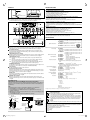
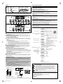
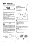
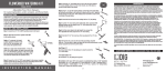
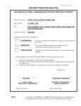
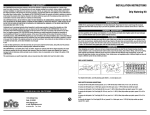
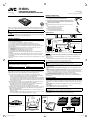
KS-AR9004
KS-AR9001D
LVT1968-001A
[J, K]
POWER AMPLIFIER: INSTRUCTIONS
AMPLIFICADOR DE POTENCIA: MANUAL DE INSTRUCCIONES
0109MNMMDWTKC
EN, SP
© 2009 Victor Company of Japan, Limited
TERMINAL CONNECTIONS
ENGLISH
When making the terminal connections…
1 Peel the insulating vinyl cover of a cord 7 mm (5/16 inch) to 10 mm
(7/16 inch) long and expose the inside conductor.
2 Loosen the hex screw in a terminal with a provided hex wrench
and insert the conductor into the terminal. Then fix the hex screw
again to secure the conductor.
Note
• The exposed conductor should be 7 mm (5/16 inch) to 10 mm (7/16 inch)
long.
– If shorter, it may cause a poor conductivity.
– If longer, it may cause a short circuit.
• Use a proper hex wrench for each terminal.
– 4 mm: +B terminal and GND terminal
– 3 mm: REM terminal and speaker terminals
Thank you for purchasing a JVC product. Please read all instructions carefully before operation,
to ensure your complete understanding and to obtain the best possible performance from the
unit.
KS-AR9001D is designed to be connected to subwoofers.
POWER SUPPLY
For safety....
• Do not raise the volume level too much, as this will block outside sounds, making driving dangerous.
• Stop the car before performing any complicated operations.
CAUTIONS AND NOTES
* Not included with this
unit.
This unit is designed to operate on 12 V DC, NEGATIVE ground electrical systems.
• This unit uses BTL (Balanced Transformerless) amplifier circuitry, i.e., floating ground system,
so please comply with the following:
Do not connect the “·” terminals of the speakers to each other.
Do not connect the “·” terminals of the speakers to the metal body or chassis.
• Cover the unused terminals with insulating tape to prevent them from short circuiting.
• When an extension lead is used, it should be as thick and short as possible; connect it firmly
with insulating tape.
• Be sure to leave an appropriate space between the antenna and the wires of this unit.
• For KS-AR9004: When replacing the fuse, only use a 40 A fuse.
For KS-AR9001D: When replacing the fuse, only use a 30 A fuse.
• Do not let pebbles, sand or metallic objects get inside the unit.
• To keep the heat dissipation mechanism running effectively, wipe the accumulated dust off
periodically.
• Listening to the tape, radio, CD or Digital Audio Player, etc. with the volume set at a high level
for a long period of time will exhaust the battery, while the engine is turned off or while the
engine is idling.
• This unit becomes very hot. Be careful not to touch the unit not only when using but for a while
after using.
40 A Fuse
To metallic body or chassis
(To an accessory terminal)
Remote turn-on line
Car battery
CAUTION
The proper lead wire connected to each POWER terminal is as follows.
• + B and GND: AWG 8 to AWG 4 (The cross section is about 8 mm2 to 21 mm2.)
• REM: AWG 18 to AWG 8 (The cross section is about 0.8 mm2 to 8 mm2.)
For Customer Use:
Enter below the Model No. and Serial No. which are located on the top or bottom of the
cabinet. Retain this information for future reference.
• If you have any questions regarding the thickness of the power cord, etc., consult your nearest
JVC car audio dealer.
a When you use JVC car receiver with a remote lead, connect to the REM terminal on this
unit.
b When you connect a unit without a remote lead, connect to the accessory circuit of the car
which is activated by the ignition switch. In this case, noise may occur when the car receiver
is turned on or off. To avoid this noise, do not turn on or off the car receiver itself. You can turn
on or off the car receiver along with the on/off operation of the ignition switch.
If the POWER/PROTECTOR lamp lights in red, it indicates incorrect speaker wiring or
connections (see “TROUBLESHOOTING” on page 3). Make sure to correct speaker wiring and
other connections.
Serial No.
INSTALLATION
The following illustration shows a typical installation. However, you should make adjustments
corresponding to your specific car. If you have any questions or require information regarding
installation kits, consult your JVC car audio dealer or a company supplying the kits.
A Mount this unit on a firm surface, such as in the trunk room or under the front seat.
• Since heat is generated in the unit, do not mount it near inflammable objects. In addition,
mount it in an area that will not prevent the unit from dissipating the heat.
• Do not mount the unit in the places subject to heat: near a radiator, in a glove compartment
or in insulated areas such as under a car mat that will prevent the unit from dissipating heat.
• When mounting the unit under the front seat, make sure that adjusting the seat position will
not catch any wire of the unit.
B When mounting this unit, be sure to use the provided screws. If any other screws are used,
the unit may not be fixed firmly or parts inside the unit may be damaged.
• Before drilling holes in the trunk to install the unit, make sure to have a sufficient space
under the trunk so that you do not drill holes in the fuel tank, etc.
• To detach and rotate the Logo Plate, use the provided hex wrench (2.5 mm).
C When you use more than one KS-AR9000 series amplifier, you can pile them up to three with
provided brackets, screws and washers in two ways, X or Y. Be sure to mount the lowest
amplifier (1) primarily following B.
• Before piling amplifiers, attach the provided spacers to the “+” marks on the bottom of the
amplifiers 2 and 3.
• Before piling amplifiers as X, first make the connections for the power supply (see “POWER
SUPPLY”) and speakers (see “SPEAKER CONNECTIONS” on page 2).
A
B
Screw—Dia. 4 mm (3/16 inch) ×
20 mm (13/16 inch)
Logo Plate
(detachable)
JVC car receiver, etc.
To prevent short circuits while making connections, keep the battery’s negative terminal
disconnected.
• When using a power cord (purchased separately), be sure to place the 40 A fuse near the
battery as shown.
• Connect the lead wire (power cord) through which power is supplied directly to the battery’s
“ª” terminal only after all the other connections have been made.
DO NOT disassemble the units since there are no user serviceable parts inside.
Model No.
Ignition switch
SPEAKER SYSTEMS
Make sure to comply with the following notes:
• Be sure not to connect the “·” terminals of the speakers to a common point.
• If the ground wire is common to both left/right and front/rear speaker wirings, this unit cannot be
used. Always use the independent lead wires for the speakers to be used. In this case, redo the
wirings.
• For KS-AR9004: Use the speakers with an impedance of 2 Ω to 8 Ω (4 Ω to 8 Ω when used in
Bridge Mode).
For KS-AR9001D: Use the speakers with an impedance of 1 Ω to 8 Ω.
• Use the speakers which have sufficient capacity to the unit.
The proper lead wire connected to each SPEAKER OUTPUT terminal is as follows.
AWG 18 to AWG 8 (The cross section is about 0.8 mm2 to 8 mm2.)
For KS-AR9004: When you connect 4 speakers to the unit, down mixed signals (front and rear)
are emitted through the PRE OUT jacks.
For KS-AR9001D: Incoming signals are emitted through the PRE OUT jacks.
C
X
Y
Bracket
Bracket
Spacer’s
bottom
Bottom
Onto the trunk room floor
Spacer
Spacer
Under the front seat
Hex screw
Drilled hole
1
EN_KSAR9004_9001D[JK]5.indd 1
09.1.15 10:16:10 AM
SPEAKER CONNECTIONS
å When your receiver is equipped with Line Output, connect the Line Output (through the
receiver) to the INPUT jacks on this unit.
∫ When your receiver is NOT equipped with Line Output, connect the provided speaker input
connector (through the receiver) to the HIGH INPUT terminal on this unit.
Connection varies depending on the number of the speakers used in your car. Select the
appropriate connection referring to the following diagrams.
Before connecting: Securely connect all the parts. If the connections are loose, due to contact
resistance etc., heat will break out and may cause an accident. Secure and cover the cords with
insulating tape and run them under the car mats.
KS-AR9004
KS-AR9001D
4-speaker system—Normal Mode
Subwoofer system
Front Speaker
(left/right)
JVC car receiver, etc.
Line Out
(Front)
Rear Speaker
(left/right)
Line Out
(Rear)
Å White (stripe)
ı White
Ç Gray (stripe)
Î Gray
Front left (–)
Front left (+)
Front right (–)
Front right (+)
Connector lead
Speaker lead
‰ Green (stripe)
Ï Green
Ì Purple (stripe)
Ó Purple
Rear left (–)
Rear left (+)
Rear right (–)
Rear right (+)
Note
Use the subwoofer with an impedance of 1 Ω
to 8 Ω.
Rear (Front) Speaker
(left/right)
Line Out
(Front)
Left (–)
Left (+)
Right (–)
Right (+)
Subwoofer
2-subwoofer system (2 amplifiers)
∫ Speaker input connector
Connector lead
Speaker lead
JVC car receiver, etc.
2-speaker system plus subwoofer—Bridge Mode
JVC car receiver, etc.
Å White (stripe)
ı White
Ç Gray (stripe)
Î Gray
Line Out (Rear)
or
Subwoofer Out
Front panel
∫ Speaker input connector
Connector lead
Speaker lead
∫ Speaker input connector
Connector lead
Speaker lead
JVC car receiver, etc.
Å White (stripe)
3 Left (–)
Ç Gray (stripe) *
ı White
Left (+)
*3
Î Gray
}
Line Out (Rear)
or
Subwoofer Out
Subwoofer
}
Line Out (Rear)
or
Subwoofer Out
Front panel
Subwoofer
∫ Speaker input connector
Connector lead
Speaker lead Connector lead
∫ Speaker input connector
Connector lead
Speaker lead
Å White (stripe)
ı White
Ç Gray (stripe)
Î Gray
Front left (–)
Front left (+)
Front right (–)
Front right (+)
Connector lead
Å White (stripe) 3
Right (–)
Ç Gray (stripe) *
}
Speaker lead
ı White
Î Gray
Speaker lead
}*
3
Right (+)
‰ Green (stripe)
3
Ì Purple (stripe) * Rear left (–)
Ï Green
Rear left (+)
3
Ó Purple *
}
}
2-speaker system—Bridge Mode
Line Out
JVC car receiver, etc.
Note
Incoming signals from INPUT jacks are
emitted through the PRE OUT jacks.
Rear (Front) Speaker
(left/right)
Subwoofer
2-subwoofer system
Front panel
∫ Speaker input connector
Connector lead
Speaker lead
JVC car receiver, etc.
Å White (stripe)
ı White
Ç Gray (stripe)
Î Gray
Line Out (Rear)
or
Subwoofer Out
∫ Speaker input connector
Connector lead
Speaker lead
Å White (stripe) 3
Ç Gray (stripe) * Left (–)
ı White 3
Left (+)
Î Gray *
}
}
Connector lead
Speaker lead
‰ Green (stripe) 3
Ì Purple (stripe) * Right (–)
Ï Green 3
Right (+)
Ó Purple *
}
}
Note
Use the subwoofers with an
impedance of 2 Ω to 8 Ω.
4-speaker system plus subwoofer (PRE OUT)
JVC car receiver, etc.
Front panel
Line Out
(Front)
Front Speaker
(left/right)
Rear Speaker
(left/right)
Subwoofer
JVC amplifier, etc.
(purchased separately)
Line Out
(Rear)
Line Out
(Rear)
JVC car receiver, etc.
Line Out
(Center)
JVC amplifier, etc.
(purchased separately)
Note
Incoming signals from INPUT jacks
are emitted through PRE OUT
jacks (down mixed from FRONT
and REAR).
*1
*2
∫ Speaker input
connector
Subwoofer
4-speaker system plus subwoofer—5.1-channel (3 amplifiers)
Line Out
(Front)
Subwoofer System
Left (–)
Left (+)
Right (–)
Right (+)
Connector lead
Speaker lead
Å White (stripe)
ı White
Ç Gray (stripe)
Î Gray
‰ Green (stripe)
Ï Green
Ì Purple (stripe)
Ó Purple
Front left (–)
Front left (+)
Front right (–)
Front right (+)
Rear left (–)
Rear left (+)
Rear right (–)
Rear right (+)
Subwoofer
Out
Front Speaker
(left/right)
Rear Speaker
(left/right)
∫ Speaker input connector
Connector lead
Speaker lead
Å White (stripe)
ı White
Ç Gray (stripe)
Î Gray
Left (–)
Left (+)
Right (–)
Right (+)
JVC amplifier, etc.
(purchased separately)
Center Speaker
*3
Not provided for this unit.
Be sure to connect the line output from the receiver to the left (L) jack on this unit.
Subwoofer
Be sure to connect the both leads to the target speaker lead.
2
EN_KSAR9004_9001D[JK]5.indd 2
09.1.15 10:16:12 AM
TROUBLESHOOTING
CONTROLS
For more details, consult your JVC car audio dealer.
The POWER/PROTECTOR lamp does not light.
• Change the fuses if the current one is blown.
• Connect the ground lead securely to a metal part of the car.
• Turn on the equipment connected to this unit.
• Use a relay if your system employs too many amplifiers.
• Confirm the battery voltage (11 V to 16 V).
Hex screw
Hex wrench (2.5 mm)
The POWER/PROTECTOR lamp lights in red and/or the unit heats up abnormally.
• Use the speakers of suitable impedance.
• Correct the speaker wirings if they are short-circuited.
• Make the speaker wirings away from the power cord to prevent DC offset error.
• Leave the unit turned off for a while to cool it down.
Control cover
To operate the following controls, remove the hex screws with a provided hex wrench
(2.5 mm) and detach the control cover. Attach it again after your operation.
No sound is heard.
• Confirm the connections for power supply (see “POWER SUPPLY” on page 1).
• Connect RCA pin cords to the INPUT jacks, or the speaker input connector to the HIGH INPUT
terminal.
KS-AR9004
Alternator noise is heard.
• Keep the power cords away from the RCA pin cords.
• Keep the RCA pin cords away from other electrical cables in the car.
• Connect the ground lead securely to a metal part of the car.
• Make sure the negative speaker leads do not touch the car chassis.
• Replace the plugs or use plugs with load resistors.
• Connect a bypass capacitor across the accessory switches (horn, fan, etc.).
KS-AR9001D
Noise is made when you connect the unit to an AM tuner.
• Move the speaker and power cords away from the antenna lead.
SPECIFICATIONS
Power Output
Signal-to-Noise Ratio
BASS BOOST controller
Turning this boosts the 45 Hz frequency within the range of 0 dB to +18 dB. Adjust the level
while listening to the sound. This controller is preset to MIN when the unit is shipped.
Input LEVEL controller
The input level can be adjusted with this controller when this unit is connected to other
source equipment. Adjust the level while listening to the sound. This controller is preset to
MIN when the unit is shipped.
CROSSOVER frequency controller
Turning this adjusts the cutoff frequency within the range of 30 Hz to 500 Hz. Adjust the level
while listening to the sound. This controller is preset to 30 Hz when the unit is shipped.
CROSSOVER filter switch
OFF: Normally, set to this position. The switch is preset to this position when the unit is
shipped.
LPF: Set to this position when you want to turn on the LPF (Low-Pass Filter) switch (the
Low-Pass Filter transmits frequencies lower than the cutoff frequency).
HPF: Set to this position when you want to turn on the HPF (High-Pass Filter) switch (the
High-Pass Filter transmits frequencies higher than the cutoff frequency).
POWER/PROTECTOR lamp
The lamp lights in green while the unit is turned on. If the lamp does not light or lights in red
with the unit on, some trouble has occurred (see “TROUBLESHOOTING”).
Power indicator
The blue lamp illuminates while the unit is turned on.
LPF (Low-Pass Filter) controller
Adjust the cutoff frequency (the Low-Pass Filter transmits frequencies lower than the cutoff
frequency) within the range of 50 Hz to 300 Hz. Adjust the level while listening to the sound.
This controller is preset to 50 Hz when the unit is shipped.
PHASE switch
Select either normal (NOM) or reverse (REV), which reproduce a better sound. This switch is
preset to NOM when the unit is shipped.
SUBSONIC filter controller
Adjust the cutoff frequency (the subsonic filter rejects frequencies lower than the cutoff
frequency) within the range of 20 Hz to 50 Hz. This controller is preset to 20 Hz when the unit
is shipped.
Power Output
Maximum Power Output
Load Impedance
Frequency Response
Input Sensitivity/Impedance
Distortion
Power Requirement
Grounding system
Dimensions (W×H×D)
Mass (approx.)
Accessories
KS-AR9001D only
Wired remote control unit: RM-RK130 (purchased separately)
Using JVC’s wired remote control unit: RM-RK130 (purchased separately), you can adjust the
bass boost in your seat without adjusting the BASS BOOST controller on the amplifier (see
“CONTROLS”).
Note
Set the BASS BOOST controller on the amplifier to MIN when you use RM-RK130.
A Mount RM-RK130 on a firm surface, such as under the dashboard.
B Connect RM-RK130 to the REMOTE terminal on the amplifier with the remote cord
provided for RM-RK130.
C RM-RK130 boosts the 45 Hz frequency within the range of 0 dB to +18 dB. Adjust the level
while listening to the sound.
• The POWER lamp lights in green while RM-RK130 is turned on.
A
Under the
dashboard, etc.
B
Screw—Dia. 4 mm (3/16 inch) × 12 mm
(1/2 inch) (provided for RM-RK130)
Information for Users on Disposal of Old Equipment and Batteries
[European Union only]
These symbols indicate that the product and the battery with this symbol should
not be disposed as general household waste at its end-of-life.
If you wish to dispose of this product and the battery, please do so in accordance
with applicable national legislation or other rules in your country and municipality.
Products
By disposing of this product correctly, you will help to conserve natural resources
and will help prevent potential negative effects on the environment and human
health.
Notice:
The sign Pb below the symbol for batteries indicates that this battery contains lead.
Battery
POWER lamp
Remote cord
(provided for
RM-RK130)
KS-AR9004:
• Normal Mode: 120 W RMS x 4 channels at 2 Ω and ≤ 1% THD + N
• Bridge Mode: 240 W RMS x 2 channels at 4 Ω and ≤ 1% THD + N
KS-AR9001D:
500 W RMS x 1 channel at 2 Ω and ≤ 1% THD + N
1 000 W RMS x 1 channel at 1 Ω and ≤ 1% THD + N
KS-AR9004:
800 W (400 W x 2)
KS-AR9001D:
1 200 W
KS-AR9004:
4 Ω (2 Ω to 8 Ω allowance)
4 Ω (4 Ω to 8 Ω allowance) (Bridge Mode)
KS-AR9001D:
4 Ω (1 Ω to 8 Ω allowance)
KS-AR9004:
5 Hz to 50 kHz*1 (+0, –3 dB)
1 Subsonic filter cuts off extremely low frequency signals less than
*
20 Hz.
KS-AR9001D:
20 Hz to 300 Hz*2 (+0, –3 dB)
*2 Subsonic filter cuts off extremely low frequency signals. (The cutoff
frequency is adjustable within the range of 20 Hz to 50 Hz.)
2 V/45 kΩ (0.3 V to 6 V, variable)
KS-AR9004:
Less than 0.04% (at 1 kHz)
KS-AR9001D:
Less than 0.1% (at 100 Hz)
DC 14.4 V (11 V to 16 V allowance)
Negative ground
360 mm × 60 mm × 245 mm (14 3/16 inch × 2 3/8 inch × 9 11/16 inch)
KS-AR9004:
4.60 kg (10.15 lbs.)
KS-AR9001D:
4.92 kg (10.85 lbs.)
Speaker input connector
KS-AR9004:
4P × 2
KS-AR9001D:
4P × 1
3/16 inch) × 20 mm (13/16 inch) × 4
Screw—Dia. 4 mm (
Hex wrench
4 mm × 1
3 mm × 1
2.5 mm × 1
Spacer × 4
Bracket × 2
Hex screw—M4 × 12 mm (1/2 inch) × 6
Design and specifications are subject to change without notice.
C
Drilled hole
KS-AR9004:
• Normal Mode: 100 W RMS x 4 channels at 4 Ω and ≤ 1% THD + N
KS-AR9001D:
• Normal Mode: 250 W RMS x 1 channel at 4 Ω and ≤ 1% THD + N
KS-AR9004: 80 dBA (reference: 1 W into 4 Ω)
KS-AR9001D: 60 dBA (reference: 1 W into 4 Ω)
Dear Customer,
This apparatus is in conformance with the valid European directives and standards regarding
electromagnetic compatibility and electrical safety.
European representative of Victor Company of Japan, Limited is:
JVC Technical Services Europe GmbH
Postfach 10 05 04
61145 Friedberg
Germany
BASS BOOST
controller
RM-RK130
3
EN_KSAR9004_9001D[JK]5.indd 3
09.1.15 10:16:13 AM
CONEXIONES DE LOS TERMINALES
ESPAÑOL
Cuando realice las conexiones de los terminales...
1 Retire la cubierta aislante de vinilo de un cable de 7 mm a 10 mm
de largo de manera que el conductor interior quede al descubierto.
2 Afloje el tornillo hexagonal del terminal con la llave hexagonal
suministrada e inserte el conductor en el terminal. Luego vuelva a
fijar el tornillo hexagonal para asegurar el conductor.
Nota
• El conductor al descubierto debe ser de un largo de 7 mm a 10 mm.
– Un largo menor podrá causar una mala conductividad.
– Un largo mayor podrá causar un cortocircuito.
• Utilice una llave hexagonal apropiada para cada terminal.
– 4 mm: Terminal + B y terminal GND
– 3 mm: Terminal REM y terminales de los altavoces
Muchas gracias por la compra de un producto JVC. Como primer paso, por favor lea
detenidamente este manual para comprender a fondo todas las instrucciones y obtener un
máximo disfrute de esta unidad.
FUENTE DE ALIMENTACIÓN
El modelo KS-AR9001D ha sido diseñado para ser conectado a subwoofers.
Para fines de seguridad....
• No aumente excesivamente el nivel de volumen, pues es muy peligroso conducir si no se
escuchan los sonidos exteriores.
• Detenga el automóvil antes de efectuar cualquier operación complicada.
PRECAUCIONES Y NOTAS
Esta unidad está diseñada para operar con sistemas eléctricos de 12 V CC, con NEGATIVO a
masa.
• Esta unidad emplea un circuito amplificador BTL (sin transformador equilibrado), es decir, un
sistema de masa flotante y por lo tanto debe cumplir con lo siguiente:
No conecte entre sí los terminales “·” de los altavoces.
No conecte los terminales “·” de los altavoces a la carrocería metálica ni al chasis.
• Cubra los terminales que no están en uso con cinta adhesiva, para evitar cortocircuitos.
• Si utiliza un cable prolongador, éste debe ser lo más grueso y corto posible; conéctelo
firmemente con cinta aislante.
• Asegúrese de dejar un espacio adecuado entre la antena y los cables de esta unidad.
• Para KS-AR9004: Cuando sea necesario cambiar el fusible, utilice solamente un fusible de 40 A.
Para KS-AR9001D: Cuando sea necesario cambiar el fusible, utilice solamente un fusible de
30 A.
• Impida la entrada de objetos metálicos, arena o piedrecillas dentro de la unidad.
• Para mantener en funcionamiento efectivo el mecanismo de disipación de calor, limpie
periódicamente el polvo acumulado.
• La batería se descargará si escucha una cinta, radio, CD o reproductor de audio digital, etc. a
un volumen alto por un tiempo prolongado, con el motor apagado o funcionando al ralentí.
• La unidad estará muy caliente. Tenga la precaución de no tocarla, no sólo durante el uso, sino
hasta un cierto tiempo después del uso.
PRECAUCION
Para evitar cortocircuitos durante las conexiones, mantenga desconectado el terminal
negativo de la batería.
• Cuando utilice un cable de alimentación (vendido separadamente), asegúrese de colocar un
fusible de 40 A cerca de la batería, tal como se observa en la ilustración.
• Conecte el conductor principal (cable de alimentación) a través del cual se suministra
directamente la alimentación al terminal “ª” de la batería únicamente después de realizar
todas las conexiones restantes.
NO desarme la unidad; en el interior no hay piezas que pueda reparar el usuario.
A continuación se indica el conductor principal apropiado que se debe conectar a cada
terminal POWER.
• + B y GND: La sección transversal es de unos 8 mm2 a 21 mm2.
• REM: La sección transversal es de unos 0,8 mm2 a 8 mm2.
INSTALACION
• Si tiene preguntas en referencia al calibre del cordón eléctrico, etc. consulte con su
concesionario más próximo de JVC de accesorios de audio para el automóvil.
a Cuando utilice un receptor para automóvil JVC con conductor remoto, conéctese al
terminal REM de esta unidad.
b Cuando conecte una unidad sin conductor remoto, conéctese al circuito de accesorios
del automóvil que se activa mediante el interruptor de encendido. En este caso, se podrían
producir ruidos al encender o apagar el receptor. Para evitarlo, puede encender o apagar el
receptor junto con las operaciones de encendido/apagado del interruptor de encendido.
Si la lámpara POWER/PROTECTOR se enciende en rojo, significa que el conexionado o las
conexiones de altavoz son incorrectas (véase “LOCALIZACIÓN DE AVERÍAS” en la página 3).
Asegúrese de corregir el conexionado y otras conexiones del altavoz.
La siguiente ilustración muestra una instalación típica. Sin embargo usted deberá efectuar los
ajustes correspondientes a su automóvil. Si tiene alguna pregunta o necesita información acerca
de las herramientas para instalación, consulte con su concesionario de JVC de equipos de audio
para automóviles o a una compañía que suministra tales herramientas.
A Instale esta unidad sobre una superficie firme, como en el baúl o debajo del asiento
delantero.
• Debido a que se genera calor en la unidad, no lo instale cerca de objetos inflamables.
Asimismo, instale la unidad en un lugar que no impida la disipación de calor.
• No coloque la unidad cerca de fuentes de calor, como el radiador, la guantera o los lugares
aislados como debajo de la alfombra, porque la unidad no podrá disipar el calor.
• Cuando instale la unidad debajo del asiento delantero, asegúrese de ajustar la posición del
asiento de manera que no quede atrapado ningún cable de la misma.
B Al instalar esta unidad, asegúrese de utilizar los tornillos suministrados. El uso de otros
tornillos podrá provocar una fijación incorrecta o daños en las piezas del interior de la unidad.
• Antes de perforar orificios en el baúl para instalar la unidad, asegúrese que haya suficiente
espacio debajo del baúl ya que podría llegar a perforar el depósito de combustible, etc.
• Para desmontar y girar la placa del logotipo, utilice la llave hexagonal suministrada (2,5
mm).
C Cuando se utilice más de un amplificador de la serie KS-AR9000, es posible apilarlos a una
altura máxima de tres unidades de dos modos distintos (X o Y) mediante los soportes, los
tornillos y las arandelas suministrados. Asegúrese de montar en primer lugar el amplificador
más bajo (1) tal y como se indica en B.
• Antes de apilar los amplificadores, acople los separadores suministrados en “+” en la parte
inferior de los amplificadores en 2 y 3.
• Antes de apilar los amplificadores como se indica en X, realice primero las conexiones de
alimentación (ver “FUENTE DE ALIMENTACIÓN”) y de los altavoces (ver “CONEXIONES
DE LOS ALTAVOCES” en la página 2).
A
B
SISTEMAS DE ALTAVOCES
Asegúrese de tener en cuenta los puntos siguientes:
• Cerciórese de no conectar a un punto común los terminales “·” de los altavoces.
• Si hay un cable de conexión a masa común para ambos conexionados de altavoces izquierdo/
derecho y delantero/trasero, esta unidad no debe ser usada. Emplee siempre cables de
conexión independientes para los altavoces en uso. En este caso, vuelva a realizar los
conexionados.
• Para KS-AR9004: Utilice los altavoces con una impedancia de 2 Ω a 8 Ω (4 Ω a 8 Ω cuando se
utiliza en el modo en puente).
Para KS-AR9001D: Utilice altavoces con una impedancia de 1 Ω a 8 Ω.
• Utilice altavoces con capacidad suficiente para la unidad.
A continuación se indica el conductor principal apropiado que se debe conectar a cada
terminal SPEAKER OUTPUT.
La sección transversal es de unos 0,8 mm2 a 8 mm2.
Para KS-AR9004:Si conecta 4 altavoces a la unidad, se emitirán señales mezcladas (delanteras
y traseras) a través de los jacks PRE OUT.
Para KS-AR9001D: Las señales entrantes se emiten a través de los jacks PRE OUT.
C
Tornillo—Dia. 4 mm × 20 mm
Placa del logotipo
(desmontable)
X
Soporte
Y
Soporte
Parte
inferior del
separador
Parte inferior
Separador
Separador
Tornillo hexagonal
1
SP_KSAR9004_9001D[JK]4.indd 1
09.1.15 9:46:33 AM
CONEXIONES DE LOS ALTAVOCES
å Cuando su receptor está equipado con salida de línea, conecte la salida de línea
(a través del receptor) a través de los jacks INPUT de esta unidad.
∫ Si su altavoz no está equipado con salida de línea, conecte el conector del altavoz
(a través del receptor) al terminal HIGH INPUT de esta unidad.
La conexión varía según el número de altavoces utilizados en su automóvil. Seleccione la
conexión apropiada refiriéndose a los diagramas siguientes.
Antes de la conexión: Todas las piezas deben quedar firmemente conectadas. Si las conexiones
están flojas, por resistencia de contacto, etc., el recalentamiento producido puede provocar accidentes.
Asegure y sujete los cables con una cinta aislante y colóquelos debajo de la alfombra del automóvil.
KS-AR9004
KS-AR9001D
Sistema de 4 altavoces—Modo normal
Sistema de subwoofer
Panel frontal
Nota
Utilice un subwoofer con una impedancia de
1 Ω a 8 Ω.
Subwoofer
Sistema de 2 subwoofers (2 amplificadores)
Sistema de 2 altavoces más subwoofer—Bridge Mode (Modo en puente)
Altavoz trasero (delantero)
(izquierdo/derecho)
Subwoofer
Panel frontal
Subwoofer
Sistema de 2 altavoces—Bridge Mode (Modo en puente)
Nota
Las señales procedentes de los jacks INPUT
se emiten a través de los jacks PRE OUT.
Altavoz trasero (delantero)
(izquierdo/derecho)
Subwoofer
Sistema de 2 subwoofers
Panel frontal
Nota
Utilice los subwoofers con
Subwoofer
una impedancia de 2 Ω a 8 Ω.
Sistema de 4 altavoces más subwoofer (PRE OUT)
Subwoofer
Sistema de 4 altavoces más subwoofer—canal 5,1 (3 amplificadores)
Amplificador JVC, etc.
(se vende por separado)
Panel frontal
Salida de
línea
(Centro)
Salida de
subwoofer
Amplificador JVC, etc.
(se vende por separado)
Amplificador JVC, etc.
(se vende por separado)
Nota
Las señales procedentes de los
jacks INPUT se emiten a través
de los jacks PRE OUT (mezcladas
desde FRONT y REAR).
*1
*2
Altavoz central
*3
No suministrado para esta unidad.
Asegúrese de conectar la salida de línea del receptor al jack izquierdo (L) de esta unidad.
Subwoofer
Asegúrese de conectar ambos conductores al conductor del altavoz objetivo.
2
SP_KSAR9004_9001D[JK]4.indd 2
09.1.14 7:21:09 PM
MANDOS
LOCALIZACIÓN DE AVERÍAS
Por más detalles consulte a un concesionario JVC de accesorios de audio para el automóvil.
La lámpara POWER/PROTECTOR no se enciende.
• Cambie los fusibles si están fundidos.
• Conecte firmemente el hilo de tierra a una parte metálica del automóvil.
• Encienda el equipo conectado a esta unidad.
• Emplee un relé si su sistema usa demasiados amplificadores.
• Compruebe el voltaje de la batería (11 V a 16 V).
Tornillo hexagonal
Llave hexagonal
(2,5 mm)
La lámpara POWER/PROTECTOR se enciende en rojo y/o la unidad se calienta anormalmente.
• Utilice altavoces de la impedancia adecuada.
• Corrija los conexionados de los altavoces si están cortocircuitados.
• Mantenga los cables de los altavoces alejados del cable de alimentación para evitar el error de
desviación de CC.
• Apague la unidad y déjela que se enfríe.
Cubierta de control
Para poder accionar los controles siguientes, retire los tornillos hexagonales con la llave hexagonal
(2,5 mm) provista y retire la cubierta de control. Vuélvala a colocar después de accionar los controles.
No se escucha sonido.
• Confirme las conexiones para la fuente de alimentación (véase “FUENTE DE ALIMENTACIÓN”
en la página 1).
• Conecte los cables de las clavijas RCA a los jacks INPUT, o el conector de entrada de altavoz
al terminal HIGH INPUT.
KS-AR9004
Se escucha ruido proveniente del alternador.
• Mantenga los cables de alimentación alejados de los cables de las clavijas RCA.
• Mantenga los cordones con clavija RCA lejos de otros cables eléctricos en el automóvil.
• Conecte firmemente el hilo de tierra a una parte metálica del automóvil.
• Asegúrese de que los conductores negativos de los altavoces no toquen el chasis del automóvil.
• Reemplace las clavijas o utilice clavijas con resistores de carga.
• Conecte un capacitor de paso entre los conmutadores auxiliares (bocina, ventilador, etc.).
KS-AR9001D
Se produce ruido al conectar la unidad a un sintonizador AM.
• Aleje los cables de los altavoces y de alimentación del conductor de la antena.
ESPECIFICACIONES
Salida de potencia
KS-AR9004:
• Modo norma: 100 W RMS x 4 canales a 4 Ω y ≤ 1% THD + N
KS-AR9001D:
• Modo normal: 250 W RMS x 1 canal a 4 Ω y ≤ 1% THD + N
Relación señal a ruido
Controlador BASS BOOST (refuerzo de bajos)
Al activarlo, la frecuencia de 45 Hz se refuerza dentro de un rango de 0 dB a +18 dB.
Ajuste el nivel mientras escucha el sonido. La unidad se expide de fábrica con este control
preajustado a MIN.
Controlador de nivel (LEVEL) de entrada
Este control permite ajustar el nivel de entrada cuando la unidad está conectada a otros
equipos fuente. Ajuste el nivel mientras escucha el sonido. La unidad se expide de fábrica
con este control preajustado a MIN.
Controlador de frecuencia CROSSOVER
Al activarlo, la frecuencia de corte se ajusta dentro del rango de 30 Hz a 500 Hz. Ajuste el
nivel mientras escucha el sonido. La unidad se expide de fábrica con este control preajustado
a 30 Hz.
Conmutador del filtro divisor
OFF: Normalmente, ajústelo a esta posición. La unidad se expide de fábrica con el
interruptor preajustado en esta posición.
LPF: Ajuste a esta posición cuando desee activar el conmutador LPF (filtro pasabajos) (el
filtro de paso bajo transmite las frecuencias inferiores a la frecuencia de corte).
HPF: Ajuste a esta posición cuando desee activar el conmutador HPF (filtro pasaaltos) (el
filtro de paso alto transmite las frecuencias superiores a la frecuencia de corte).
Lámpara POWER/PROTECTOR
La lámpara se enciende en verde mientras la unidad está encendida. Si la lámpara no se
enciende o se enciende en rojo con la unidad encendida, significa que ha ocurrido algún
problema (véase “LOCALIZACIÓN DE AVERÍAS”).
Indicador de alimentación
La lámpara azul permanece iluminada mientras la unidad está encendida.
Controlador de LPF (filtro contra el paso de bajas frecuencias)
Ajuste la frecuencia de corte entre 50 Hz y 300 Hz (el filtro contra el paso de bajas
frecuencias transmite frecuencias inferiores a la frecuencia de corte). Ajuste el nivel mientras
esté escuchando el sonido. Este control está preajustado en 50 Hz en el momento de entrega.
Interruptor PHASE
Seleccione normal (NOM) o inversa (REV), que reproduce un mejor sonido. La unidad se
expide de fábrica con este control preajustado a NOM.
Controlador de filtro SUBSONIC
Ajuste la frecuencia de corte entre 20 Hz y 50 Hz (el filtro subsónico rechaza las frecuencias
que sean inferiores a la frecuencia de corte). Este control está preajustado en 20 Hz en el
momento de entrega.
Salida de potencia
KS-AR9004:
• Modo normal:
120 W RMS x 4 canales a 2 Ω and ≤ 1% THD + N
• Bridge Mode (Modo en puente):
240 W RMS x 2 canales a 4 Ω y ≤ 1% THD + N
KS-AR9001D:
500 W RMS x 1 canal a 2 Ω y ≤ 1% THD + N
1 000 W RMS x 1 canal a 1 Ω y ≤ 1% THD + N
Máxima potencia de salida
KS-AR9004:
800 W (400 W x 2)
KS-AR9001D:
1 200 W
Impedancia de carga
KS-AR9004:
4 Ω (tolerancia de 2 Ω a 8 Ω)
4 Ω (tolerancia de 4 Ω a 8 Ω) (Modo en puente)
KS-AR9001D:
4 Ω (tolerancia de 1 Ω a 8 Ω)
Respuesta de frecuencias
KS-AR9004:
5 Hz a 50 kHz*1 (+0, –3 dB)
*1 El filtro subsónico suprime las señales de las frecuencias
extremadamente bajas, inferiores a 20 Hz.
KS-AR9001D:
20 Hz a 300 Hz*2 (+0, –3 dB)
*2 El filtro subsónico suprime las señales de las frecuencias
extremadamente bajas. (La frecuencia de corte puede ajustarse
dentro del intervalo de 20 Hz a 50 Hz.)
Sensibilidad/Impedancia de entrada 2 V/45 kΩ (0,3 V a 6 V, variable)
Distorsión
KS-AR9004:
Inferior a 0,04% (a 1 kHz)
KS-AR9001D:
Inferior a 0,1% (a 100 Hz)
Requisitos de potencia
14,4 V CC (tolerancia de 11 V a 16 V)
Sistema de puesta a tierra
Negativo a masa
Dimensiones (An/Al/Pr)
360 mm × 60 mm × 245 mm
Peso (aprox.)
KS-AR9004:
4,60 kg
KS-AR9001D:
4,92 kg
Accesorios
Conector de entrada de altavoz
KS-AR9004:
4P × 2
KS-AR9001D:
4P × 1
Tornillo—Dia. 4 mm × 20 mm × 4
Llave hexagonal
4 mm × 1
3 mm × 1
2,5 mm × 1
Separador × 4
Soporte × 2
Tornillo hexagonal—M4 × 12 mm × 6
El diseño y las especificaciones se encuentran sujetos a cambios sin previo aviso.
KS-AR9001D solamente
Unidad de mando a distancia con cable: RM-RK130 (se vende por separado)
Uso de la unidad de mando a distancia con cable: RM-RK130 (se vende por separado);
permite ajustar el refuerzo de graves desde su asiento sin tener que ajustar el controlador de
BASS BOOST del amplificador (ver “MANDOS”).
Nota
Ajuste el controlador de BASS BOOST del amplificador en la posición MIN cuando use RM-RK130.
A Coloque el RM-RK130 sobre una superficie firme, como por ejemplo debajo del tablero.
B Conecte el RM-RK130 al terminal REMOTE del amplificador con el cable remoto
suministrado para el RM-RK130.
C El RM-RK130 refuerza la frecuencia de 45 Hz dentro de un rango de 0 dB a +18 dB.
Ajuste el nivel mientras esté escuchando el sonido.
• La luz POWER se enciende en verde cuando el RM-RK130 se activa.
A
B
Información para los usuarios sobre la eliminación de equipos y baterías/pilas usados
[Sólo Unión Europea]
Estos símbolos indican que el producto y la batería que llevan este símbolo no
deben desecharse junto con la basura doméstica al final de su vida útil.
Si desea desechar este producto y la batería, hágalo de conformidad con la
legislación nacional vigente u otras normativas de su país y municipio.
Productos Si desecha el producto correctamente, estará contribuyendo a conservar los
recursos naturales y a prevenir los posibles efectos negativos en el medio
ambiente y en la salud de las personas.
Atención:
La indicación Pb debajo del símbolo de batería/pila indica que ésta contiene plomo.
C
Debajo del tablero, etc.
Luz POWER
Orificio perforado
KS-AR9004: 80 dBA (referencia: 1 W en 4 Ω)
KS-AR9001D: 60 dBA (referencia: 1 W en 4 Ω)
Baterías/pilas
Cable remoto
(suministrado
para el RMRK130)
Tornillo—Dia. 4 mm × 12 mm
(suministrado para el RM-RK130)
Apreciado cliente,
Este aparato cumple con las normativas y normas europeas respecto a la seguridad eléctrica y
a la compatibilidad electromagnética.
El representante europeo de Victor Company of Japan, Limited es:
JVC Technical Services Europe GmbH
Postfach 10 05 04
61145 Friedberg
Alemania
Controlador de
BASS BOOST
RM-RK130
3
SP_KSAR9004_9001D[JK]4.indd 3
09.1.14 7:21:10 PM