1
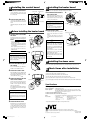
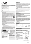
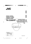
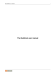
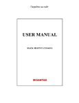
®
KA-H205U
Heater unit
INSTRUCTIONS
Thank you for purchasing the JVC option hater unit.
To obtain the best results from your new camera, read these instructions carefully before use;
retain the manual for future reference.
For Customer Use:
Enter below the Serial No. which is located on the body.
Retain this information for future reference.
● Do not modify this machine without prior permission. Accidents may occur.
Serial No.
These instructions are for KA-H205U
These are general IMPORTANT SAFEGUARDS and certain items may not apply to all appliances.
IMPORTANT SAFEGUARDS
5.
6.
7.
8.
9.
10.
11.
12.
13.
14.
15.
16.
17.
18.
● To save energy, turn the power off when not in use.
● This unit is a special heater for TK-C205VPU (A) Dome camera. It cannot be installed to other
color video cameras.
● Use AC 24 V power supply for TK-C205VPU (A).
Model No.
1.
2.
3.
4.
PRECAUTIONS
Read all of these instructions.
Save these instructions for later use.
All warnings on the product and in the operating instructions should be adhered to.
Unplug this appliance system from the wall outlet before cleaning. Do not use liquid cleaners or aerosol cleaners.
Use a damp cloth for cleaning.
Do not use attachments not recommended by the appliance manufacturer as they may cause hazards.
Do not use this appliance near water - for example, near a bathtub, washbowl, kitchen sink, or laundry tub, in a
wet basement, or near a swimming pool, etc.
PORTABLE CART WARNING
Do not place this appliance on an unstable cart, stand, or table. The appliance may fall,
(symbol provided by RETAC)
causing serious injury to a child or adult, and serious damage to the appliance may fall,
causing serious injury to a child or adult, and serious damage to the appliance.
Use only with a cart or stand recommended by the manufacturer, or sold with the appliance.
Wall or shelf mounting should follow the manufacturer’s instructions, and should use a
mounting kit approved by the manufacturer.
An appliance and cart combination should be moved with care. Quick stops, excessive
force, and uneven surfaces may cause the appliance and cart combination to overturn.
S3125A
Slots and openings in the cabinet and the back or bottom are provided for ventilation, and
to insure reliable operation of the appliance and to protect it from overheating, these openings must not be
blocked or covered. The openings should never be blocked by placing the appliance on a bed, sofa, rug, or
other similar surface. This appliance should never be placed near or over a radiator or heat register. This
appliance should not be placed in a built-in installation such as a bookcase unless proper ventilation is provided.
This appliance should be operated only from the type of power source indicated on the marking label. If you are
not sure of the type of power supplied to your home, consult your dealer or local power company. For appliance
designed to operate from battery power, refer to the operating instructions.
For added protection for this product during a lightning storm, or when it is left unattended and unused for long
periods of time, unplug it from the wall outlet and disconnect the antenna or cable system. This will prevent
damage to the product due to lightning and power-line surges.
Do not allow anything to rest on the power cord. Do not locate this appliance where the cord will be abused by
persons walking on it.
Follow all warnings and instructions marked on the appliance.
Do not overload wall outlets and extension cords as this can result in fire or electric shock.
Never push objects of any kind into his appliance through cabinet slots as they mat touch dangerous voltage
points or short out parts that could result in a fire or electric shock. Never spill liquid of any kind on the appliance.
Do not attempt to service this appliance yourself as opening or removing covers may expose you to dangerous
voltage or other hazards. Refer all servicing to qualified service personnel.
Unplug his appliance from the wall outlet and refer servicing to qualified service personnel under following
conditions:
a. When the power cord or plug is damaged or frayed.
b. If liquid has been spilled into the appliance.
c. If the appliance has been exposed to rain or water.
d. If the appliance does not operate normally by following the operating instructions. Adjust only those controls
that are covered by the operating instructions as improper adjustment of other controls may result in damage
and will often require extensive work by a qualified technician to restore the appliance to normal operation.
e. If the appliance has been dropped or the cabinet has been damaged.
f. When the appliance exhibits a distinct change in performance - this indicates a need for service.
When replacement parts are required, be sure the service technician has used replacement parts specified by
the manufacturer that have the same characteristics as the original part. Unauthorized substitutions may result
in fire, electric shock, or other hazards.
Upon completion of any service or repairs to this appliance, ask the service technician to perform routine safety
checks to determine that the appliance is in safe operating condition.
For USA and CANADA
CAUTION
RISK OF ELECTRIC SHOCK
DO NOT OPEN
CAUTION: TO REDUCE THE RISK OF ELECTRIC SHOCK.
DO NOT REMOVE COVER (OR BACK).
NO USER SERVICEABLE PARTS INSIDE.
REFER SERVICING TO QUALIFIED SERVICE PERSONNEL.
The lightning flash with arrowhead
symbol, within an equi-lateral triangle,
is intended to alert the user to the presence of uninsulated “dangerous voltage” within the product’s enclosure that
may be of sufficient magnitude to constitute a risk of electric shock to
persons.
The exclamation point within an equilateral triangle is intended to alert the
user to the presence of important operating and maintenance (servicing) instructions in the literature accompanying the appliance.
● Refer to the “Instructions” for TK-C205VPU (A) on installing the camera and connecting the
cables.
● After installing to TK-C205VPU (A), switch off the machine power supply and then connect.
● Always use the desiccant that comes with this unit. Other desiccants or the silica gel that comes
with TK-C205VPU (A) are unable to remove moisture completely under extreme low temperature.
● When the heater board is installed, the switch on the camera unit is hidden and image adjustment
cannot be made. Always adjust the image quality before installing the heater.
● Do not use the heater unit in the following locations:
• Locations where the surrounding temperature exceeds -40˚F to 122˚F (-40˚C to 50˚C).
• Locations where corrosive gas occurs.
• Vibrating locations
Contents
JVC
Instructions
1
Warranty Card
1
Heater board
1
Desiccant
(Service Parts
No.LW40790-001A)
1
Service
Information Card
1
Control board
1
Screw assy
2
Installation Method
● This unit consists of a heater board and a control board. Install these two boards to TKC205VPU (A).
1
Disassembling TK-C205VPU (A)
● Switch off the power supply of the camera.
1.
Dome cover
2.
Inner cover
Wrench
1. Remove the dome cover
Loosen the 3 screws on the dome cover
that secures it with the wrench that comes
with TK-C205VPU (A).
2. Remove the camera unit
Loosen the screws on the camera unit in
the order of 1 and 2, and remove the
camera unit from the base.
Camera unit
2
1
WARNING:
TO PREVENT FIRE OR SHOCK HAZARD, DO NOT EXPOSE THIS UNIT TO RAIN OR MOISTURE.
Base
Information for USA
This device complies with Part 15 of the FCC Rules.
Changes or modifications not approved by JVC could void the user’s authority to operate the equipment.
INFORMATION (FOR CANADA) RENSEIGNEMENT (POUR LE CANADA)
This Class [B] digital apparatus complies with Canadian ICES-003.
Cet appareil numérique de la classe [B] est conforme à la norme NMB-003 du Canada.
Due to design modification, data given in this instruction book are subject to possible change without prior notice.
WARNING:
This installation should be made by a qualitied service person and should conform to all
local codes.
3. Remove the inner cover
Press A, B sections lightly and remove the
inner cover. After removing the inner cover
from the camera unit, fold the 4 catches
and remove the ring section.
3.
A section
B section
B section
A section
CAUTION :
Once the ring section of the inner cover is
removed, it cannot be placed back.
KA-H205U_LWT0260-001A-H
1
05.2.17, 9:21 AM
Catch
2 Installing the control board
1. Install the control board
Install the heater after adjusting the field angle and lens of the camera.
Terminal board
Control boardn
Use the supplied two screw assy on the
left side of the terminal board and install
the control board.
2. Connect the CN4 cable
Connect the CN4 cable on the control
board to the CN4 terminal on the terminal
board.
Meanwhile, bring the CN5 cable out of the
base.
4 Installing the heater board
1. Install the heater board to
the camera unit
Rotate the heater in the direction of the
arrow such that the claw (B section) of the
heater board is hooked on the notch (A
section) of the camera unit.
CN5
Cable
the base
Put the desiccant that comes with this unit
inside the base and secure with a lug plate.
CAUTION
CN4 terminal
Screw assy
(attached)
• Pay attention when installing the heater
board to the camera unit as there is a
correct direction.
• The dome cover cannot be installed if the
heater board is not installed securely.
CN4 cable
3 Before installing the heater board
1. Put the desiccant inside
1.
Desiccant
2. Connect the cable
Connect the CN5 cable of the control
board to the CN5 cable of the heater
board.
Once the CN5 cables are connected,
insert them between the base and camera
unit.
Memo:
Lug plate
Silver packaging
3.
2
Refer to TK-C205VPU (A) “INSTRUCTIONS” for the installation method.
6 Check items after installation
3. Install the camera unit
Check the following items after installation.
□ Is the power supply for TK-C205VPU (A) AC 24 V?
5.
□ Have you inserted the desiccant that comes with this unit?
□ Are the CN5 cables inserted between the base and camera unit?
□ Does the cable touch the components such as resistors on the heater board?
4. Adjust the field angle and
When the heater board is installed, the
switch on the camera unit is hidden and
image adjustment cannot be made. Always
adjust the image quality before installing the
heater.
5. Install the inner cover
Mount the inner cover such that the tilt lock
screw can be seen from the hole on C
section. When mounting, make sure that
the notch of the inner cover comes to the
direction which the lens of the camera is
facing.
5 Installing the dome cover
Refer to TK-C205VPU (A) “INSTRUCTIONS” for the installation method of the dome cover.
the ceiling
CAUTION
Tilt lock screw
Notch
□ Does an image appear normally on the monitor after switching on the power for TK-C205VPU (A)?
Specifications
C section
Power supply / Voltage : AC 24 V ± 10%, 60 Hz/50 Hz (recommended)
Power consumption : 15 W (during AC 24 V)
Heater operation
: Surrounding temperature -40˚F to 32˚F (-40˚C to 0˚C) (auto on/off)
*By using this unit, the operation guarantee temperature of the camera
becomes -40˚F to 122˚F (-40˚C to 50˚C).
Locations free from vibration and shock
Locations free from salt erosion and corrosive gases
Mass
: 100˝ (total mass of heater board, control board, desiccant and screw assy)
Accessories
: • Instructions ............. 1
• Warranty Card ............... 1
• Service Information
• Desiccant (Service Parts
Card ........................ 1
No. LW40790-001A) ...... 1
• Heater unit .............. 1
• Screw assy .................... 2
* Design and specifications are subject to change without notice.
®
®
®
is a Registered Trademark owned by Victor Company of Japan, Limited.
is a Registered Trademark in Japan, the U.S.A., the U.K. and many other countries.
© 2005 Victor Company of Japan, Limited
KA-H205U_LWT0260-001A-H
2
CN5 cable of heater board
• Make sure that the cable does not touch
the components such as resistors on the
heater board.
2. Install TK-C205VPU (A) on
Switch on the power supply of the camera.
Refer to TK-C205VPU (A) “INSTRUCTIONS” on how to adjust the field angle
and lens of the camera.
After adjusting the field angle and lens of
the camera, switch off the power supply
of the camera.
CN5 cable of control board
• Heater elements could be hot! When
camera power is on, use with caution
when adjusting the camera.
1
lens of the camera
B section
2.
• When connecting CN5 cable of the control
board to the CN5 cable of the heater
board under cold weather conditions
below 50˚F (10˚C), the heater will turn ON
automatically and become very hot. Avoid
being scalded.
Always use the desiccant that comes with
this unit. Other desiccants or the silica gel
that comes with TKC205VPU (A) are unable
to remove moisture completely under
extreme low temperature.
Align 1 and 2 of the base with 1 and 2
of the camera unit and tighten with screws.
When doing this, tighten the screws of the
camera unit in the order of 1, 2.
A section
CAUTION
• Remove the desiccant from its silver
packaging before use.
• Always replace the desiccant during
repair, reconnection during maintenance
or reinstallation.
When replacing the desiccant, use a
desiccant with Service Par ts No.
LW40790-001A.
CAUTION
Heater board
1.
05.2.17, 9:22 AM
Printed in Thailand
LWT0260-001A-H