1
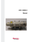
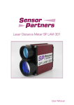
Laser Distance Meter SP LAM 53 User Manual 2 Revision 003, May 2007 Dear User You are advised to carefully read this User Manual before powering on the SP LAM 53 laser distance measuring module for the first time. This is necessary to ensure that you will be able to utilize all the capabilities and features which your new acquisition provides. This technology is subject to continuously ongoing development. Editorial deadline: May 2007 Document number 012840-006-98-02-0507 Sensor Partners BV James Wattlaan 7 5151 DP Drunen Holland Phone: +31 (0) 516-378239 Fax: +31 (0) 516-377539 Web: www.sensor.nl E-Mail: [email protected] Revision state Date Revision May 2007 003 Explanation Modified CE Note No part of this User Manual may be reproduced in any way (by photographing, photocopying, microfilm or any other technique) without prior written approval by JENOPTIK Laser, Optik, Systeme GmbH, nor may it be processed, duplicated or disseminated with the help of electronic systems. Proper care has been used in compiling this document. No liability will be accepted Revision 003, May 2007 3 Dear User For highlighting purposes, the following pictograms, signs of reference and warning symbols are used throughout this Manual: • Enumeration + Advice/Important/Important Note Reference (to a passage of text or a Figure) Warning symbols Warning: Indicates potential health risks that may occur if symbols of this type are disregarded. Caution: Warns of potential product damage. Laser: Warns of potential exposure to emerging visible or invisible laser radiation. Information: Provides a reference to important data or details. 4 Revision 003, May 2007 Content 1 2 2.1 2.2 2.3 2.4 2.5 3 3.1 3.2 3.3 4 4.1 4.2 4.3 4.4 4.5 4.5.1 4.5.2 4.5.3 4.5.4 4.5.5 4.5.6 4.5.7 4.5.8 4.6 4.7 4.8 5 6 6.1 6.1.1 6.1.2 6.1.3 6.1.4 6.1.5 6.2 6.2.1 6.2.2 6.2.3 6.2.4 6.2.5 6.2.6 6.2.7 General..................................................................................................... 7 Safety Instructions..................................................................................... 9 Basic Notes................................................................................................ 9 Laser Classification..................................................................................... 9 Electric Supply........................................................................................... 9 Important Operating Advice...................................................................... 9 Danger Signs & Specification Plates.......................................................... 10 Intended & Conforming Use.....................................................................11 General Product Description.....................................................................11 Conforming Use.......................................................................................11 Nonconforming Use................................................................................ 12 Product Description................................................................................. 13 Scope of Delivery..................................................................................... 13 Technical Data......................................................................................... 13 Mechanical Mounting Conditions............................................................ 15 Connector Pin Assignments..................................................................... 16 Profi bus Interface.................................................................................... 17 ID Number.............................................................................................. 17 Interfacing Requirements......................................................................... 17 GSD File................................................................................................... 17 Slave Address.......................................................................................... 17 Bus Termination....................................................................................... 17 Baud Rate............................................................................................... 17 Segment Length...................................................................................... 17 Wiring Diagram....................................................................................... 18 SSI Interface............................................................................................ 19 Alarm Outputs......................................................................................... 20 Trigger Input............................................................................................ 22 Start-Up................................................................................................... 23 SP LAM 53 Operation.............................................................................. 25 Measuring Modes.................................................................................... 25 DM: Single Distance Measurement........................................................... 25 DT: Distance Tracking............................................................................... 25 DW: Distance Tracking With White Target (10 Hz).................................... 25 DX: Distance Tracking With Cooperative Target (50 Hz)............................ 25 DF: Distance Measurement with External Trigger...................................... 26 Parameters.............................................................................................. 26 Class 2 Function...................................................................................... 26 Extended Diagnostics.............................................................................. 26 Scale Factor............................................................................................. 26 Trigger Mode........................................................................................... 27 Trigger Level............................................................................................ 27 Trigger Delay........................................................................................... 27 Error Reaction.......................................................................................... 27 Revision 003, May 2007 5 Content 6.2.8 6.2.9 6.2.10 6.2.11 6.2.12 6.2.13 6.2.14 7 7.1 7.2 7.3 7.4 7.5 7.6 7.7 7.8 8 9 9.1 9.2 10 11 12 6 Measuring Time....................................................................................... 27 Display Offset.......................................................................................... 28 6.2.10 Switching Point Output 1 or 2....................................................... 28 Hysteresis Output 1 or 2.......................................................................... 28 Diagnostic Interval................................................................................... 29 Average................................................................................................... 29 Factory Settings....................................................................................... 29 Profibus Interface..................................................................................... 31 General Information................................................................................ 31 Slave Address Setting............................................................................... 31 Selection of Operating Mode................................................................... 32 Configuration Data.................................................................................. 32 Cyclical Data Exchange – Input (Slave -> Master)...................................... 32 Cyclical Data Exchange – Output (Master -> Slave)................................... 33 Parameter data........................................................................................ 34 Diagnostic data....................................................................................... 35 Preventive Care & Maintenance................................................................ 37 Malfunction & Error Reports.................................................................... 39 Malfunction............................................................................................. 39 Error Report Outputs via Profi bus............................................................ 39 EC - Declaration of Conformity................................................................ 41 Abbreviation listing.................................................................................. 53 Index....................................................................................................... 44 Revision 003, May 2007 General 1 General The SP LAM 53 is an opto-electronic distance measuring module for industrial applications. Equipped with a Profibus® DP interface, the SP LAM 53 can easily be integrated into any fieldbus-driven process controller. The additional SSI interface provides another convenient option for controlled operation of the measuring module. A compact and robust design shape combines with low power consumption, selectable switching outputs and the possibility to set specific application parameters to warrant flexibility in use. You should not start using the SP LAM 53, unless you have read this User Manual and familiarized yourself with all safety notes contained in it. This is necessary to ensure that your opto-electronic distance measuring module can be used in the best possible way and damage will be prevented. Revision 003, May 2007 7 General 8 Revision 003, May 2007 Safety Instructions 2 Safety Instructions 2.1 Basic Notes These safety and operating instructions should be carefully read and followed during practical work with the SP LAM 53. There is danger of laser radiation or electrical shock. For necessary repair work, the SP LAM 53 may not be opened by anyone other than Manufacturer personnel. Unauthorized intervention into the inner product space will void any warranty claims. Compliance with all specified operating conditions is necessary. Failure to observe advisory notes or information contained in this Manual or nonconforming product usage may cause physical injury to the user or material damage to the SP LAM 53. Cable connectors must not be plugged or unplugged, as long as voltage is supplied. Remember to turn voltage supply off before you begin working on cable connections. 2.2 Laser Classification The LAM51/52 is a class 2 laser product as stipulated in IEC825-1/DIN EN 608251:2001-11 and a class II product under FDA21 CFR. In the event of accidental, shorttime laser exposure, the human eye is sufficiently protected by its own optico-facial winking reflex. This natural reflex may be impaired by medication, alcohol and drugs. Although the product can be operated without taking special safety precautions, one should refrain from directly looking into the laser beam. Do not direct the laser beam onto persons. Caution: There is class 2 laser radiation. Do not look into the beam! 2.3 Electric Supply Use only 10 V to 30 V direct voltage for SP LAM 53 operation. Use only the specially designated connector terminal for voltage supply. Specified signal levels must not be exceeded, in order to guarantee correct data communication. 2.4 Important Operating Advice To make full use of the system’s inherent performance capabilities and achieve a long service life, you should always follow these operating rules: • Do not turn the SP LAM 53 on if there is fogging or soiling on its optical parts! • Do not touch any of the module’s optical parts with bare hands! • Proceed with care when removing dust or contamination from optical surfaces! Revision 003, May 2007 9 Safety Instructions • Prevent exposure to shock impacts during transportation of the SP LAM 53! • Prevent overheating of the SP LAM 53! • Prevent major temperature variances during SP LAM 53 operation • In accordance with IP65 internal protection standards, the SP LAM 53 is designed to be splashproof and dustproof. Read these safety and operating instructions with due care and follow them in practical use. 2.5 Danger Signs & Specification Plates Connection JENOPTIK Laser, Optik, Systeme GmbH Typ LDM43 SerNr. 05 0020 Power DC 24 V / 3,2 W op. Temp. -10°C...+50°C Profibus DPV0-Slave SSI 100kHz, 24bit, gray Internal protection class IP65 Made in Germany GERMANY CE PIN A PIN B PIN C PIN D PIN E PIN F PIN G PIN H PIN J PIN K PIN L PIN M SSI C+ SSI CTrig n.c. SSI DSSI D+ V24 n.c. GND Alarm2 n.c. Alarm1 white brown green yellow grey pink blue red black violet grey/pink red/blue LASER RADIATION DO NOT STARE INTO BEAM CLASS II LASER PRODUCT P<0,95mW l=620 … 690 nm EN 60825-1: 2001-11 - - 10 Revision 003, May 2007 Intended & Conforming Use 3 Intended & Conforming Use 3.1 General Product Description The SP LAM 53 is a laser distance measuring module to determine distances from 0.1 m to 30 m, using natural surfaces, or to measure distances up to 150 m with a target reflector. Providing a red laser sighting point, the SP LAM 53 allows you to unequivocally mark a particular target. Its effective operating range depends on the reflectance and surface qualities of the targets being sighted. The module works based on comparative phase measurement. It emits modulated high-frequency light which is diffusely reflected back from the target with a certain shift in phase to be compared with a reference signal. From the amount of phase shift, a required distance can then be determined with millimeter accuracy. A distance measurement cycle can be triggered: • via the Profibus • from an external trigger source (external trigger mode) • via the SSI. Special performance features are: • Profibus interface • Broad range of parameter setting options via Profibus • SSI interface • Two switching outputs, each with selectable parameter settings • External trigger input, with selectable parameter settings • Capable of operating at outdoor temperatures from +15°C to +30°C with ±2 mm accuracy • Up to 30 m reach for distance measurement, with potential for 150 m reach if additional reflectors are mounted onto the target • Visible laser beam for easier sightingl. The SP LAM 53 measuring module is shipped in a rugged cardboard box with adequate padding for safe transportation. 3.2 Conforming Use • Measurement of distances and output of measured data to the Profibus. • Special measuring functions. • Compliance with prescribed temperatures for operation and storage. • Operation at correct voltage level. • Application of specified signal levels to the appropriate data lines. Revision 003, May 2007 11 Intended & Conforming Use 3.3 12 Nonconforming Use • Do not operate the SP LAM 53 in any other way than described under “Intended & Conforming Use“ above and only in a proper working condition. • Safety devices must not be defeated or otherwise rendered ineffective. • Information and warning signs must not be removed. • Repair work on the SP LAM 53 must not be carried out by anyone other than JENOPTIK personnel. • Refrain from using the SP LAM 53 in an explosive environment. • Measurement with the SP LAM 53 pointed at the sun or other strong lightsources may produce faulty results. • Measurement of targets with poor surface reflectance in a strongly reflecting environment may also result in faulty measurement values. • Measurement of strongly reflecting surfaces may deliver faulty results. • Measurement performed through transparent optical media, for example, glass, optical filters, plexiglass, etc. may equally produce incorrect results. • Rapidly changing measuring conditions are likely to falsify the result of measurement. Revision 003, May 2007 Product Description 4 Product Description 4.1 Scope of Delivery Description SP LAM 53 CD with Customer documentation Optional accessories Power chord, 2 m Power chord, 5 m Power chord, 10 m 12-pole jack Profibus terminator, M12 Profibus 5-pole jack Profibus 5-pin plug Profibus-in-out cable, 5m Profibus-in cable jack, 5m Profibus-in cable jack, 10m Profibus-out cable plug, 5m Profibus-out cable plug, 10m Screw cap for Profibus jack Screw cap for Profibus plug Set of Customer documentation (hardcopy) 4.2 Part number 012840-530-22 012840-144-24 012840-145-24 012840-146-24 28509 94145 94136 94133 012840-170-24 012840-165-24 012840-166-24 012840-160-24 012840-161-24 95363 95366 Technical Data Measuring Performance Measuring principle Measuring parameter Measuring range *1 Measuring accuracy Target surface Target board required Measured value resolution Reproducibility Measuring time Max. carrier motion speed *1 Comparative phase measurement Distances 0.1 m ... 30 m for natural, diffusely reflecting surfaces, and up to 150 m with a target board ± 2 mm for white surfaces, (+15 °C ... +30 °C) ± 3 mm for natural surfaces, (+15 °C ... +30 °C) ± 5 mm (-10 °C ...+50 °C) Of natural, diffusely reflecting type From 30 m to 150 m 0.1 mm ≤ 0.5 mm 0.16 sec ... 6 sec on white target board (10 Hz mode) 20 msec on white target board (50 Hz mode) 4 m p. sec in “DX” operating mode conditional on target reflectance, ambient light influences and atmospheric conditions Revision 003, May 2007 13 Product Description Laser Laser class Laser beam divergence Wavelength Laser class 2, ≤ 1 mW conforming to standard IEC 825-1 / EN 60825 0.6 mrad 650 nm (red, visible) Electric Power Requirements Supply voltage 10 V ... 30 V DC Max. power consumption 3.2 W at 24 V Interface Data interface Baud rate GSD file SSI interface Operation modes Switching output Trigger input Profibus RS485 Ident. no. 0x09CB Profibus DP-V0 slave under IEC 61158 / IEC 61784 External termination resistor 9.6 / 19.2 / 93.75 / 187.5 / 500 kbaud 1.5 / 3 / 6 / 12 Mbaud Automatic baud rate detection LAM409CB.GSD PNO Profile Encoder Class 1/2 Configuration of measuring parameters Output of measured values and error messages Parameters and PB-address are stored in NVRAM Transfer rate: 50 kHz ... 1 MHz, 200 µs break Signal input to signal output differential signal (RS422), 24bit, gray-encoded, Slave Electrical isolation to 500 V for signal input Continuous measurement external triggering Two outputs with HIGH signal level VCC -2 V and LOW signal level < 2 V; max. load carrying capacity 0.5 A, short-circuit-proof; switching threshold and hysteresis selectable One input with HIGH signal level > 11 V and LOW signal level < 6.5 V 2.5 mA input current at 24 V Trigger edge and delay selectable Trigger pulse of max. 24 V Environment & Ambient Conditions Operating temperature -10 °C ... +50 °C with automatic laser diode shut down on excession of temperature limits Temperature measurement Internal Storage temperature -20 °C ... +70 °C Humidity < 65% Dimensions (L x W x H) 210 mm x 96 mm x 50 mm Weight 770 g Protection type IP 65 EMC EN 61000-6-2, EN 55011 14 Revision 003, May 2007 Product Description 4.3 Mechanical Mounting Conditions The casing consists of a rugged, corrosion-resistant extruded aluminum profile with front-side and rear-side covers also in corrosion-resistant design. Four mounting holes are provided in the baseplate for mechanical attachment of the SP LAM 53. ( Fig. 2 Dimensional drawing ). 6 1 4 5 3 2 7 8 9 11 10 12 Fig. 1: SP LAM 53 Captions 1 Housing (extruded aluminum profile, powder-coated) 7 Mechanical mounting holes (4x, Ø = 6,6 mm) 2 Equalizer tube (anodized) 8 Receiver optics 3 Front cover (anodized) 9 Sender optics 4 Back cover (anodized) 10 Profibus-IN (M12) 5 Laser warning sign 11 Profibus-OUT (M12) 6 Specification plate 12 Power inlet To protect the range finder’s optical surfaces from dust, physical contact, mechanical impacts, etc., the casing has a special equalizer tube attached to it. Please note that measurement cannot be guaranteed to function correctly if the equalizer tube is removed by unqualified action! Revision 003, May 2007 15 Product Description 5,5 16 100±,2 96 5,5 85 ∅ 6,6 (4x) 7 Figure 2 Offset against zero-edge (Dimensions in mm) The SP LAM 53’s zero-point is located 7 mm behind the outer surface of the front cover or 137 mm before the back cover outside face respectively. This zero-point has been introduced for constructional design reasons. 4.4 Connector Pin Assignments white brown green Profibus-IN green yellow red gray pink Profibus-IN blue red black green violet gray/pink red red/blue Device terminal Profibus-OUT Profibus-OUT Power inlet Fig. 3: Pinning diagram For operation via Profibus, other Profibus participants may connect to the 5-pole jack (A-wire, B-wire). The Profibus may terminate or continue at the 5-pole connector. Some kind of termination device must always be provided at the end of the Profibus. Supply voltage for the bus terminator is available at Profibus-OUT. 16 Revision 003, May 2007 Product Description 4.5 Profibus Interface 4.5.1 ID Number The SP LAM 53 has been registered with “PROFIBUS Nutzerorganisation e.V. (PROFIBUS User Organization, incorporated society) under ID number 09CB (HEX). 4.5.2 Interfacing Requirements The SP LAM 53 is prepared for connection to any type of Profibus DP structure. The related Profibus DP Master must be capable of sending a parameterization telegram. The Master’s own configuring tool (typically configuring software) must support representation of the parameters which are contained in the SP LAM 53 Master file (GSD file). 4.5.3 GSD File The GSD file is named LAM409CB.GSD. It includes the two files “SP LAM 53.dib” and “SP LAM 53.bmp” which are necessary for representation of the SP LAM 53 in the configuring tool. For information regarding integration of these files, please consult the special documentation parts that relate to the configuring tool. 4.5.4 Slave Address A Profibus address can be assigned, with due consideration of other participants in bus communications, to any number from 0 to 125. The setting of an address can be achieved by triggering an SSA command via the Profibus. For details on how to change a previously set slave address via the configuring tool, you should consult the special tool documentation. In as-delivered state, the slave is set to the address “4”. A currently set slave address is permanently stored in the EEPROM. It is also preserved in the event of a power failure. Where more than one slave (SP LAM 53) communicates via one Profibus, they must be connected in series and each of them must be assigned a different address. 4.5.5 Bus Termination For SP LAM 53 operation, the bus must be fitted with an external terminator. 5 V supply voltage for bus termination can be drawn from the Profibus-OUT. This voltage is electrically isolated from actual operating voltage supply (VCC) and provides 100 mA current load capacity. The terminating resistor is available as an accessory item. 4.5.6 Baud Rate The SP LAM 53 is prepared to automatically detect any of the following baud rates: 9.6 / 19.2 / 93.75 / 187.5 / 500 kbaud and 1.5 / 3 / 6 / 12 Mbaud, respectively. 4.5.7 Segment Length The maximum segment length between Profibus participants depends on the selected baud rate. The following segment length requirements must be met: Revision 003, May 2007 17 Product Description Baud rate [baud] Segment length [m] 9.6 k – 93.75 k 1200 187.5 k 1000 500 k 400 1.5 M 200 3 M – 12 M 100 For cabling in accordance with these segmenting limits, you are stongly recommended to use cable of type A. This cable type provides the following performance features: Surge impedance 135 ... 165 W Capacitance per unit length ≤ 30 pf/m Loop impedance ≤ 110 W/km Wire diameter > 0.64 mm Wire cross-section > 0.34 mm² 4.5.8 Wiring Diagram white green brown green red yellow gray pink Profibus-IN blue Voltage supply red black violet gray/pink green red/blue Device terminal red Profibus-OUT Fig. 4: Minimum wiring configuration of Profibus interface 18 Revision 003, May 2007 Product Description 4.6 SSI Interface Parameter settings for SSI interface operation can be made via the Profibus. Default state set on initial product delivery: DT Mode. The SP LAM 53 has a SSI data interface (SSI = synchronous serial interface). At the request of a SSI clock generator, the SP LAM 53 triggers a distance measurement cycle, sending the data bit by bit to a controller for processing in the same order as it arrives at the shift register. This process occurs in the measuring mode that was most recently stored in the SP LAM 53. A desired measuring mode can be selected via the Profibus. Transfer rates from 50 kHz to 1 MHz are available for selection. Selections should always take into account the actual cable length. The SSI interface works independently of the Profibus interface. It provides a data length of 24 bits and uses Gray code. The pause interval between two bit sequences is 200 µsec. All interface inputs are electrically isolated. They provide an isolation strength of 500 V. To guarantee undisturbed data transmission, screened twisted-pair cables have to be used. This requirement is met by the cable type which you can find quoted in the optional accessories section above ( Scope of Delivery). The following table shows selectable clock rates with corresponding cable lengths that must not be exceeded: Clock rate [kHz] Cable length [m] < 500 < 25 < 400 < 50 < 300 < 100 < 200 < 200 < 100 < 400 For SSI interface operation, the wiring diagram is as follows: Revision 003, May 2007 19 Product Description white Steuerung brown green yellow gray pink blue Spannungsversorgung red black violet gray/pink red/blue Device terminal Fig. 5: Wiring for SSI interface operation 4.7 Alarm Outputs Parameter settings for alarm outputs can be made via Profibus. This function is only available with the Profibus in active state. Each of the two alarm outputs allows a given object or state to be monitored for positive or negative excession of its limit values. This is achieved with the help of a user-definable distance threshold value (AC). Which way the particular alarm output will switch depends on the mathematical sign of its hysteresis. Rule: Positive hysteresis: With increasing distance, the output switches from LOW to HIGH, as soon as AC + AH/2 is exceeded, with decreasing distance, it switches from HIGH to LOW, as soon the distance value falls below AC – AH/2. Negative hysteresis: With increasing distance, the output switches from HIGH to LOW, as soon as AC + |AH/2| is exceeded, with decreasing distance, it switches from LOW to HIGH, as soon the distance value falls below AC – |AH/2|. HIGH HIGH AH AH LOW LOW AC Distanz AC Distanz Fig. 6: Digital switching output behaviour for positive and negative hysteresis. LOW corresponds to a voltage level < 2 V. HIGH corresponds to a voltage level of VCC - 2 V. 20 Revision 003, May 2007 Product Description Each alarm output is short-circuit proof and rated for a maximum current load of 0.5 A. Parameter settings for alarm outputs can be made with the Profibus master, using the Encoder profile with Class 1 functionality. The following parameters may be configured (refer to GSD File): ExtUserPrmData = 29 “Switching point output 1 (31-16)” for AC alarm output 1 ExtUserPrmData = 30 “Switching point output 1 (15-0)” for AC alarm output 1 ExtUserPrmData = 31 “Switching point output 2 (31-16)” for AC alarm output 2 ExtUserPrmData = 32 “Switching point output 2 (15-0)” for AC alarm output 2 ExtUserPrmData = 33 “Hysteresis output 1 (31-16)” for AH alarm hysteresis 1 ExtUserPrmData = 34 “Hysteresis output 1 (15-0)” for AH alarm hysteresis 1 ExtUserPrmData = 35 “Hysteresis output 2 (31-16)” for AH alarm hysteresis 2 ExtUserPrmData = 36 “Hysteresis output 2 (15-0)” for AH alarm hysteresis 2 Further switching functionalities, for example, monitoring for specified operating ranges may be accomplished by combining the two alarm outputs. The wiring diagram for utilization of alarm outputs is as follows: white brown green Controller green yellow red gray pink Profibus-IN blue Voltage supply red black violet gray/pink Application red/blue Device terminal green Profibus-OUT -> red Profibus-OUT Fig. 7: Wiring for alarm outputs Revision 003, May 2007 21 Product Description 4.8 Trigger Input Parameter settings for the trigger input can be made using Profibus tools. This function is only enabled with the Profibus in active state. The trigger input allows a distance measurement cycle to be triggered by an external signal that is applied as a voltage pulse. Available setting options are the delay time (Trigger Delay) until measurement actually starts and the pulse edge to be selected for triggering (Trigger Level). Trigger mode (0 ... Off, 1 ... On) must be turned on. Parameter settings for Trigger Input can be made with the help of the Profibus Master, using the Encoder profile and Class 2 encoder functionality. The following parameters are available for configuration (refer to GSD File): ExtUserPrmData = 20 “Trigger Mode” for trigger mode ExtUserPrmData = 21 “Trigger Level” for trigger level ExtUserPrmData = 25 “Trigger Delay (31-16)” for trigger delay ExtUserPrmData = 26 “Trigger Delay (15-0)” for trigger delay For detection of a clock edge, the following voltage signals are required: 24 V 0V > HIGH < LOW > 11 V < 6.5 V Wiring connections for working with the trigger input are as follows: white green brown Controller green red yellow gray pink Profibus-IN blue Voltage supply red black violet gray/pink Application red/blue Device terminal green Profibus-OUT -> red Profibus-OUT Fig. 8: Wiring of trigger input 22 Revision 003, May 2007 Start-Up 5 Start-Up The table below proposes a sample procedure that may be followed for SP LAM 53 start-up. It does not purport to provide complete information or exhausting details on all possible applications. For this description, it is assumed that the user will match cabling to his/her specific requirements. No. Working step 1 Unpack SP LAM 53 and inspect for visible damage 2 Connect and firmly screw on Profibus terminals 3 Connect and firmly screw on device terminals in power-off state 4 Turn voltage supply on 5 Trigger distance measurement (laser comes on and Profibus or SSI launches measurement) 6 Sight a given target using the visible laser spot 7 Lock the SP LAM 53 in position 8 Perform final visual inspection Revision 003, May 2007 23 Start-Up 24 Revision 003, May 2007 SP LAM 53 Operation 6 SP LAM 53 Operation 6.1 Measuring Modes The various measuring modes are distinguished by the algorithms they use for calculation. The SP LAM 53 relies on the phase comparison method for normal operation. In order to obtain a precise measured value, the user should perform an appropriate number of single distance shots at different frequencies of a fixed number. For DW mode and DX mode, the number of frequencies and/or the number of single distance shots is limited, which allows for higher measurement frequencies. On the other hand, this also places tighter demands on the quality of operating conditions, for example, targets should be strongly reflecting. The resulting limitations should be taken into account by the user in practical work. In DT mode or DM mode, the user may define his/her own limits for the maximum time which measurement is to last, by setting appropriate measuring time values in Measuring Time. 6.1.1 DM: Single Distance Measurement In DM mode, a single distance shot is triggered. A desired measuring time can be set in the Master’s configuring tool, using the Encoder profile and Class 2 encoder functionality. 6.1.2 DT: Distance Tracking DT mode can be chosen for distance measurement of different kinds of surfaces (varying reflectance). This may cause longer measuring times in the case of poor reflectance or sudden jumps in distance. The minimum measuring time is 160 msec, the maximum time is 6 sec. On expiry of six seconds, measurement will be aborted with an error message. A desired Measuring Time can be set in the Master’s configuring tool, using the Encoder profile and Class 2 encoder functionality. 6.1.3 DW: Distance Tracking With White Target (10 Hz) DW mode uses a steady measuring rate of 10 Hz. A white target board is a necessary prerequisite for measured values to be stable. There must be no sharp jumps in distance above a value of 16 cm within the area being measured. 6.1.4 DX: Distance Tracking With Cooperative Target (50 Hz) DX mode uses a steady measuring rate of 50 Hz. It is primarily intended for applications where there is uniform carrier motion up to a rate of 4 m p. sec. The high measuring rate of 50 Hz is achieved by involving previously measured values in calculation of a currently measured value. Distance jumps greater than 16 cm should be avoided. A white target board is a necessary prerequisite for stable distance readings. Revision 003, May 2007 25 SP LAM 53 Operation 6.1.5 DF: Distance Measurement with External Trigger In DF mode, measurement begins on arrival of an external trigger pulse. This trigger pulse releases a single distance shot. Desired settings for the Measuring Time, the trigger edge (“Trigger Level”) and the delay in triggering (“Trigger Delay”) can be made in the Master’s configuring tool, using the Encoder profile and Class 2 encoder functionality. Trigger mode must be active. 6.2 Parameters Settings can be made for each parameter in the Master configuration tool, using the Encoder profile and Class 2 encoder functionality. For a description, you should refer to the special configuring tool documentation. The configuring tool of the Master uses the GSD file as input to create parameters for the slave. It must have sent these parameters at least once to the slave before the slave will be able to work in cyclical data exchange mode. The slave has been programmed with enough tolerance to allow operation with only its seven byte standard PB parameters (i.e. without any profile-adapted user parameters). Where the Master is unable to send user parameters, the EEPROM’s previously stored parameters will be used. This may make sense in SSI encoder applications without involvement of a Profibus. In such cases, the SP LAM 53 must be parameterized once, using the Profibus. The selected parameter settings must then be saved, the Profibus disabled again and the SSI interface terminal be activated. 6.2.1 Class 2 Function Selects slave type according to Encoder profile. 6.2.2 Extended Diagnostics Transmits more than six standard diagnostic bytes (16 bytes as Class 1 Slave, 61 bytes as Class 2 Slave). 6.2.3 Scale Factor Scale factor (SF) multiplies a calculated distance value with a factor that can be selected within the range from – 10.00000 to + 10.00000 to allow changes in resolution setting or output of results in a unit of measure other than the metric system. Up to five positions after decimal point can be processed. To make settings for profibus system operation, SF needs to be multiplied with 100,000. The resulting number must then be converted into a 32-bit hexadecimal number. In profibus setup mode, a mathematically obtained number can be entered at bytes (Octet) 55 ... 58 of the table of parameter setup data. 26 SF Resolution Long integer Byte 55 Byte 56 Byte 57 Byte 58 10 1 -1 -10 0.1 mm 1 mm 1 mm 0.1 mm 0 0 F F 4 8 7 B 4 A 6 C 1,000,000 100,000 - 100,000 - 1,000,000 0 0 F F 0 0 F F F 1 E 0 2 6 9 D 0 0 0 0 Revision 003, May 2007 SP LAM 53 Operation SF Resolution Long integer Byte 55 0.3937 1 inch 3.28084 0.01 feet 1.0936 0.01 yard 39,370 328,084 109,360 0 0 0 0 0 0 Byte 56 Byte 57 Byte 58 0 0 0 9 0 A C 9 3 0 5 1 9 1 B A 4 0 6.2.4 Trigger Mode Trigger Mode enables (1) or disables (0) external triggering. 6.2.5 Trigger Level Trigger Level defines if measurement will start on a rising (0) or a falling (1) pulse edge. 6.2.6 Trigger Delay Trigger Delay sets the time from the arrival of a trigger pulse to the actual beginning of measurement. It may correspond to any value between 0 and 9999 msec. 6.2.7 Error Reaction Error Reaction defines how the alarm outputs will react if a measurement cycle is found to have been unsuccessful. Different setting options are available in order to cause error messages to trigger different kinds of response as appropriate for a particular environment in which the SP LAM 53 operates. Possible settings are 0, 1 and 2 with the following assigned effects upon occurrence of an error message Error reaction Alarm outputs 0 Preserves latest valid measurement state 1 Positive alarm hysteresis = LOW, negative alarm hysteresis = HIGH 2 Positive alarm hysteresis = HIGH, negative alarm hysteresis = LOW 6.2.8 Measuring Time Measuring Time is active in DM and DT measuring mode. As a general rule, it may be assumed that the poorer the surface quality of a targeted object the more time will be required by the SP LAM 53 to determine that target’s distance with specified accuracy. For example, if error message E15 is output because of poor reflectance and too small a measuring time value, the setting for measuring must be increased. The available range for measuring time variation is 0 to 25. Note: The greater the value which is selected for measuring time the longer the time which will be available for measurement and the smaller the frequency at which measurement will be performed. “0” value setting is an exception. In this case, the SP LAM 53 will use its internal Revision 003, May 2007 27 SP LAM 53 Operation criteria for evaluation. In addition, by varying the Measuring time, one may also configure the measuring frequency. This may prove helpful where data volumes have to be restricted. The following provides an approximated measuring time equation: Measuring time » Measuring time × 240 ms (> 0) Because different factors may result in frequency shifts, this equation can only be given in an approximated relationship. 6.2.9 Display Offset On selection of Display Offset, a desired amount of offset may be applied to the measured value (for correction). 6.2.10 Switching Point Output 1 or 2 Switching Point Output 1 or 2 corresponds to the trigger threshold of alarm output 1 or 2 respectively. The trigger threshold behaviour is user-definable. For settings of this kind, a switching hysteresis parameter is provided (refer to section 6.2.11). 6.2.11 Hysteresis Output 1 or 2 Hysteresis Output 1 or 2 corresponds to the switching hysteresis of alarm output 1 and 2 respectively. Your settings for switching hysteresis define: • how a switching output will respond to the positive or negative excession of a trigger threshold, depending on the mathematical sign of a hysteresis value • what range will be covered by the switching output, depending on the amount of hysteresis. The following table shows switching output behaviour depending on the mathematical sign of hysteresis: Trigger threshold positively exceeded Trigger threshold negatively exceeded Positive hysteresis HIGH LOW Negative hysteresis LOW HIGH HIGH HIGH AH AH LOW LOW AC 28 Distanz AC Distanz Revision 003, May 2007 SP LAM 53 Operation Fig. 10: Behaviour of digital switching output for positive and negative hysteresis 6.2.12 Diagnostic Interval Diagnostic Interval allows you to define how often diagnostic reports are to be output. A diagnostic report includes information about (but not limited to) the inner device temperature. For generation of diagnostic data, a running distance measurement will be interrupted! The available setting range for Diagnostic Interval is from 0 to 10000. The time scale is 100 msec. If Diagnostic Interval is set to “0”, diagnostic data will only be output if there was an error. Consequently, a setting of “10000” for Diagnostic Interval will correspond to an interval of 1000 sec. 6.2.13 Average Average allows a floating mean value to be calculated from one to twenty measured single values. Calculation is based on this formula: Mean value x = x1 + x2 + x3 + ... + xn (20) n 6.2.14 Factory Settings Slave Address 1 Measuring Mode DT Scaling Function 0 Trigger Mode 0 Trigger Level 0 Trigger Delay 0 Error Reaction 0 Measuring Time 0 Display Offset 0 Switching Point Output 1 10000 Switching Point Output 2 20000 Hysteresis Output 1 100 Hysteresis Output 2 100 Diagnostic Interval 10 Average Revision 003, May 2007 1 29 SP LAM 53 Operation 30 Revision 003, May 2007 Profibus Interface 7 Profibus Interface 7.1 General Information The Profibus Interface for SP LAM 53 operation control is identical with the Standard DP V0 Profibus (with peripherals decentralized) where V0 designates the version. Telegrams are byte-oriented. A byte is also referred to as an Octet in Standard Profibus terminology. From a user’s point of view, the following types of telegrams are required to accomplish communication: - cyclical data exchange telegrams (DataEx) - diagnostic telegrams - parameter setup telegrams The various Profibus slaves of identical or similar functionality are described in profiles. These make it easier for users to work with PB slaves from different manufacturers, which provide identical functionality. For operation of the SP LAM 53 in Profibus mode, the encoder profile of the Profibus (order no. 3062 of PNO) is supported. The SP LAM 53 works as a linear encoder in this case. Within the available encoder profile capabilities, the SP LAM 53 can work as a class1 or class2 encoder (recommended). All versions are accomplished via a GSD file. In addition to specific profile data, the SP LAM 53 provides specific device settings. These concern laser control and diagnosing aspects. Profile Class Functionality Encoder class 1 - only input - simple diagnosis - minimal parameter setup options class 2 - input and output (Preset) - extended diagnosis - extended parameter setup otions SP LAM 53 7.2 class 1 - see encoder profile class 2 - additional vendor-specific diagnosis and parameter setups Slave Address Setting Slave address 4 is factory-set. Changes can be made via the Profibus Master. A desired address can be assigned using the SSA (Set Slave Address) signal. Revision 003, May 2007 31 Profibus Interface 7.3 Selection of Operating Mode DT measuring mode is factory-set. Changes can be implemented in parameter setup mode, using bits 5 ... 7 of parameter setup byte 26. 0 = 000 = DF 1 = 001 = DT 2 = 010 = DW 3 = 011 = DX 4 = 100 = DM Where modified data are to be written onto the EEPROM, bit 4 of parameter setup byte 26 must be set to ’1’. 7.4 Configuration Data For input and output data, the following configurations are available: mandatory class 1 D1 hex 2 words input consistency class 2 F1 hex 2 words of input data, 2 words of output data for preset value, consistency optional class 1 D0 hex not implemented in SP LAM 53 class 2 F0 hex 7.5 not implemented in SP LAM 53 Cyclical Data Exchange – Input (Slave -> Master) The SP LAM 53 outputs position data which are mathematically signed. The SF (scale factor) parameter can be used to invert a given mathematical sign. Resolution is also defined via SF. Octets in a telegram are arranged in a Profibus-compliant manner (big endian), i.e. the MSB always comes first and the LSB is always the last one. Octet 1…4 32 Bit Type Output signed 32 position data from encoder Revision 003, May 2007 Profibus Interface 7.6 Cyclical Data Exchange – Output (Master -> Slave) The most significant bit in a preset value (bit 32) defines the validity of that preset. Octet Bit 1…4 Type Output signed 32 preset-value standard mode: MSB = 0 (bit 31) preset mode : MSB = 1 (bit 31) The “Preset“ value is available for setting a current output value to a desired value. This is achieved with the help of an internal offset Moffset. By setting of bit 31, this offset value can be changed. The following assignments are valid: MDataEx value transported to the Profibus in cyclical data exchange mode MLaser reading determined by the laser Moffset intern calculated offset value MPreset value transferred with “Preset“ function - Cyclical calculation of: MDataEx = MLaser + Moffset - The value for Moffset is not permanently stored in the SP LAM 53, i.e. it will be lost on turning power off. The offset value can also be stored as a parameter in Octet 32 ... 35. - If bit 31 of MPreset is set, MOffset will be calculated in such a manner that the following equation is met: MPreset = MLaser + Moffset. The new offset value can be read in the diagnostic data as Octet 30 ... 33. Revision 003, May 2007 33 Profibus Interface 7.7 Parameter data The following minimum parameter setups apply to class 1 devices: Octet 1 2 3 4 5 ... 6 7 8 9 Bit 0 1 2 3 4 5 6 7 Type byte byte byte byte word byte byte bool bool bool bool bool bool bool bool Output station status (profibus default) wd_fact_1 (watch dog) (profibus default) wd_fact_2 (profibus default) min_tsdr (profibus default) word ident number (profibus default) group ident (profibus default) spc3 spec (profibus default) unused class 2 functionality on/off commissioning diagnostic on/off commissioning diagnostic on/off reserved for future use reserved for future use reserved for manufacturer reserved for manufacturer The following additional parameters apply to class 2 devices: Octet Bit 10 … 13 Type unsigned 32 14 … 17 18 … 25 unsigned 32 byte(s) 26 0 1 2 ... 3 4 5 ... 7 27 28 ... 31 32 ... 35 36 ... 39 40 ... 53 44 ... 47 48 ... 51 52 ... 53 54 55 ... 58 34 Output unused – linear encoder (Measuring units per revolution) linear encoder (Measuring range in ..) unused – (reserved for future use) bool bool 2 bit number bool unused trigger level 0 = H gL 1 = L g H (TDnn x) error reaction 0 … 2 (SEnn) 0= non action 1= write on EEPROM (store all parameters) 3 bit number measure mode (0 = DF, 1 = DT, 2 = DW, 3 = DX, 4 = DM) byte measure time [STnn] 0 ... 25 signed 32 trigger delay [TDnn] 0 ... 9999 signed 32 display offset [OFnnnn] signed 32 output1 switch limit 0 ... 5000000 [ACnn] signed 32 output2 switch limit 0 ... 5000000 [ACnn] signed 32 output1 switch hysterese –5000000 ... 5000000 [AHnn] signed 32 output2 switch hysterese –5000000 ... 5000000 [AHnn] word diag update time in 0.1 sec byte average time [SAnn] 1 ... 20 signed 32 scale factor [SFnn] n*0.00001 (1.0 = 100000) Revision 003, May 2007 Profibus Interface Since the SP LAM 53 is a linear encoder that measures absolute distances, the four parameters “code sequence”, ”scaling function control“, ”Measuring units per revolution“ and ”Measuring range in measuring units“ will be ignored. 7.8 Diagnostic data Class 2 functionality 0 1 Octet 1 2 3 4 5 ... 6 7 8 9 Bit 0 1 2 3 4 5 6 7 10 11 ... 14 15 ... 16 17 18 ... 19 Commissioning diagnostic 0 1 1 Type byte byte byte byte word byte byte bool bool bool bool bool bool bool bool byte unsigned 32 unsigned 16 0 1 0 1 2 3 bool bool bool bool bool bool 4 bool Revision 003, May 2007 Output diag state 1 diag state 2 diag state 3 master address ident number Diagnostic information 6 byte standard diagnosis 16 byte class 1 diagnosis 61 byte class 2 diagnosis (profibus default) (profibus default) (profibus default) (profibus default) (profibus default) class 1 diagnostic group ident (profibus default) spc3 spec (profibus default) unused class 2 functionality on/off commissioning diagnostic on/off unused reserved for future use reserved for future use reserved for manufacturer reserved for manufacturer (operation status: parameter byte 9) encoder type (=7 absolute linear encoder) single turn resolution => 100000nm = 0.1mm no. of distinguishable revolutions – unused (=0) class 2 diagnostic E98 – timeout SIO E99 – unknown error E15 – reflex signal too weak, use target boardn E16 – reflex signal too strong, use target board E17 – steady light (e.g. insolation) E18 – only in DX-mode (50 Hz): variance between measured and precalculated value too great E23 – temperature below –10 °C 35 Profibus Interface Octet Bit 5 6 Type bool bool 7 bool 8 9 bool bool 10 11 12 bool bool bool 13 bool 14 15 20 ... 21 22 ... 23 24 ... 25 26 ... 27 28 ... 31 32 ... 35 36 ... 39 40 ... 53 bool bool word word word word unsigned 32 signed 32 signed 32 unsigned 32 44 ... 47 48 ... 57 58 ... 59 60 61 unsigned 32 10 byte word signed byte byte Output E24 – temperature above +60 °C E31 – wrong EEPROM checksum, hardware errorr E51 – failure to set avalanche voltage of laser diode; cause: stray light or hardware error E52 – laser current too strong / defective laser E53 – failure to set one or more parameters in EEPROM (consequence: division by 0) E54 – hardware error (PLL) E55 – hardware error E61 – selected parameter is illegal; invalid command was triggered E62 – 1. hardware error 2. false value for interface communications (SIO parity error) E63 – SIO overflow E64 – SIO framing error warnings – unused (=0) warnings – unused (=0) profile version (z.B. 1.1 = 0110 hex) software version (z.b. 1.11 = 0111 hex) operating time (of laser), in units of 0.1 hour offset value (also refer to Output Data) manufacture offset – unused (=0) unsigned 32 measuring units per revolution – unused (=0) unsigned 32 measuring range – unused (=0) 10 byte serial number word reserved for future use laser temperature in °C reserved - unused Since the SP LAM 53 is a linear encoder that measures absolute distances, the four parameters “code sequence”, ”scaling function control“, ”Measuring units per revolution“ and ”Measuring range in measuring units“ will be ignored . 36 Revision 003, May 2007 Preventive Care & Maintenance 8 Preventive Care & Maintenance Please note: • To remove dust from optical glass surfaces (of transmitter or receiver optics), you may use a pneumatic brush. Do not use solvent-containing cleaners to wipe optical surfaces down. You are advised to contact the Manufacturer if there is contamination of a more obstinate nature. • Refrain from the use of solvents for cleaning work. • You are prohibited from opening the SP LAM 53. • Do not release any screws of the SP LAM 53. In the event of necessary repair work, you are requested to carefully pack the SP LAM 53 away, indicate its particular operating environment (applications, communication & wiring details, environmental conditions) and send it back to your local distributor (or to us at the following address): Sensor Partners BV James Wattlaan 7 5151 DP Drunen Holland Phone: +31 (0) 516-378239 Fax: +31 (0) 516-377439 Web: www.sensor.nl E-Mail: [email protected] Revision 003, May 2007 37 Preventive Care & Maintenance 38 Revision 003, May 2007 Malfunction & Error Reports 9 Malfunction & Error Reports 9.1 Malfunction Error situation Cause Action for removal No data coming via Profi- Faulty Profibus bus configuration Device error (Ext. diagnosis) 9.2 Check Profibus configuration Hardware problems Reship SP LAM 53 for repair, contact technical support Errror Report Outputs via Profibus Code Cause Action for removal E15 Excessively poor reflexes Use target board, observe minimum requirement on measuring distance (> 0.1 m) E16 Excessively strong reflexes Use target board, do mot measure against reflecting surfaces E17 Too much steady light (e.g. sun) Mount SP LAM 53 in such a position that excessive incidence of steady light is prevented, extend glare protection tube, provide additional light-shielding, e.g. protective cap E18 Only in DX mode: too Check path from distance meter to target much difference between being measured for obstacles measured and pre-calculated value E23 Temperature below –10°C Provide ambient temperature > -10°C E24 Temperature above +60°C Provide ambient temperature < +60°C E31 Faulty EEPROM checksum, Service required if fault occurs repeatedly hardware error Reship SP LAM 53 for repair E51 Failure to set avalanche voltage 1. straylight 2. hardware error 1. Check target reflectance and ambient light (steady light), make sure that neither target not entry opening of SP LAM 53 is exposed to light from reflecting surfaces, projectors or sun) 2. Service required reship for repair E52 Laser current too high / laser defective Reship SP LAM 53 for repair Contact technical support E53 Hardwarefehler Reship SP LAM 53 for repair Contact technical support E54 Hardware error Reship SP LAM 53 for repair Contact technical support E55 Hardware error Reship SP LAM 53 for repair Contact technical support E61 Hardware error Service required if occurring repeatedly Reship SP LAM 53 for repair E62 Hardware error Check RS232 settings; if fault persists, reship SP LAM 53 for repair, contact technical support Revision 003, May 2007 39 Malfunction & Error Reports 40 Code Cause Action for removal E63 SIO overflow Check time of emitted signals in application software, integrate delay on transmission if necessary E64 SIO framing error Reship SP LAM 53 for repair Contact technical support Revision 003, May 2007 EC - Declaration of Conformity 10 EC - Declaration of Conformity Revision 003, May 2007 41 EC - Declaration of Conformity 42 Revision 003, May 2007 Abbreviation listing Code Cause Action for removal E98 Reship SP LAM 53 for repair Contact technical support 11 Hardware error Abbreviation listing DF Distance Measurement with External Trigger DM Single Distance Measurement DT Distance Tracking DW Distance Tracking With White Target (10 Hz) DX Distance Tracking With Cooperative Target (50 Hz) GSD-Datei Devica Data Base File ID number SP LAM 53 registration number at “Profibus Nutzerorganisation e.V.“ LSB Least Significant Bit MSB Most Significant Bit SSI Synchronous Serial Interface Revision 003, May 2007 43 Index 12 Index A Linear encoder 36 Alarm outputs 20 Assignments, Connector pin 16 M B Baud rate 14, 17, 18 Bus termination 17 C Carrier motion speed 13 Cleaning 37 Connector pin assignments 16 D Data Exchange, Input 32 Data Exchange, Output 33 Data interface 14 Diagnosedaten 35 Diagnostic data 35 Distance 11 Distance Tracking 25 Divergence 14 E Electric power requirements 14 Electric supply 9 Error reports 39 F Factory settings 29 G GSD file 14, 17 I ID number 17 L Laser beam divergence 14 Laser class 13 Laser classification 9 Laser radiation 9 44 Maintenance 37 Malfunction 39 Measured value resolution 13 Measuring accuracy 13 Measuring mode 25 Measuring modes 25 Measuring range 13 Measuring time 13 Mechanical Mounting Conditions 15 Mounting conditions, mechanical 15 O Operating temperature 14 Operation mode 14 P Parameter 34 Parameter data 34 Parameterdaten 34 Parameters 26 Phase measurement, comparative 11 Power consumption 14 Power requirements, electric 14 Preventive care 37 Profibus 11, 17, 31 Profibus Interface 31 Profibusschnittstelle 31 R Reproducibility 13 Resolution 13 S Scope of delivery 13 Single Distance Measurement 25 Slave 31 Slave Address 31 Slave address 17 Specification plate 10 Revision 003, May 2007 Index SSI interface 7, 14, 19 Storage temperature 14 Supply, electric 9 Supply voltage 14 Switching output 14 T Target surface 13 Technical data 13 Trigger input 14, 22 W Wavelength 14 Revision 003, May 2007 45 46 Revision 003, May 2007