1
O TRO_ BILT
Operator's Manual
Rear-tine Tiller Models
630Cn
634Fm
634Bm
Tuffy_
BroncoTM
Super BroncoTM
Model 634B Shown
IMPORTANT:
WARNING:
READ SAFETY RULES AND INSTRUCTIONS
This unit is equipped with an internal combustion
CAREFULLY
engine and should not be used on or near any unimproved
forest-
covered, brush-covered or grass-covered land unless the engine's exhaust system is equipped with a spark arrester meeting applicable
local or state laws (if any). If a spark arrester is used, it should be maintained in effective working order by the operator. In the State of
California the above is required by law (Section 4442 of the California Public Resources Code). Other states may have similar laws.
Federal laws apply on federal lands. A spark arrester for the muffler is available through your nearest engine authorized service dealer or
contact the service department, P.O. Box 361131 Cleveland, Ohio 44136-0019.
TROY-BILT
PRINTEDIN U.S.A.
LLC, P.O. BOX 361131 CLEVELAND,
OHIO 44136-0019
FORM NO. 770-10594B
11/5/02
TABLEOFCONTENTS
Content
Page
Calling Customer Support .......................................................................................................2
Safety......................................................................................................................................3
Assembly................................................................................................................................6
Freaturesand Controls ............................................................................................................10
Operation................................................................................................................................12
Maintenance...........................................................................................................................17
Off-SeasonStorage.................................................................................................................21
Troubleshooting......................................................................................................................22
Parts List ................................................................................................................................23
Warranty Information ..............................................................................................................Back Cover
FINDINGMODELNUMBER
This Operator's Manual is an important part of your new Rear-tine Tiller. It will help you assemble, prepareand maintain the unit for
best performance. Pleaseread and understand what it says.
information from it in the space providedbelow. This information isvery importantif you need help from our Customer
Beforeyou
start assemblingyournew
equipment,pleaselocate the model plateon the equipment and copy the
Support Department
or an authorized dealer.
You can locate the model number by looking on the rear surface of the tine shield. A sample model plate is explainedbelow. For
future reference,pleasecopy the model number and the serial number of the equipment in the space below.
Copythe model numberhere:
O TRII_BILT
www.troybilt.com
•
Copythe serial numberhere:
• _."__-_ _. _
CLEVELAND,
OH44136
330-558-7220
866-840-648_
ENGINEINFORMATION
Theengine manufacturer is responsiblefor all engine-related issueswith regard to performance, power-rating, specifications,
warranty and service. Pleaserefer to the engine manufacturer's Owner's/Operator's Manual packed separatelywith your unit for more
information.
CALLINGCUSTOMER
SUPPORT
If you have difficulty assemblingthis product or have any questions regarding the controls, operation or maintenanceof this unit,
pleasecall the Customer Support Department.
Call1- (330) 558-7220 or 1- (866) 840-6483 to reacha Customer Support representative.Pleasehaveyour unit's
model number and serial number readywhen you call. See previous section to locate this information. You will be
askedto enter the serial
SECTION1: SAFETY
This machinemeetsvoluntarysafetystandardB71.8-1996, whichis sponsoredbythe
OutdoorPowerEquipmentInstitute,Inc.,
and is publishedbythe AmericanNational
StandardsInstitute.
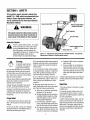
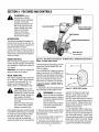
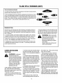
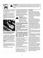
ForwardClutchO_
Reverse Clutch Control
(Models634F/634B)
WARNING
Depth Regulator
The engine exhaust from this productcontains
chemicals known to the State of California to
cause cancer, birth defects or other reproduc-
/
Tine HoodFlap
SafetyAlert Symbol
in thisis manual
the unit Ittoisalert
This
a safetyand
alertonsymbol.
used
you to potential hazards. When you
see this symbol, read and obey the
message that follows it. Failure to obey
safety
messages could result in
persona I injury or property damage.
Training
_ _
"_,_/,_
1., Carefully readthis Owners Manual. the separate
Engine Owner's Manual
and any other literature you may receive.
Be thoroughly familiar with the controls
and the proper use of the tiller and its engine. Know how to stop the unit and disengage the controls quickly.
2. Neverallow children to operatethe tiller.
Never allow adults to operatethe tiller
without proper instruction.
3. Keep the area of operation clear of all
persons, particularly children and pets
4. Keep in mind that the operator or user is
responsible for accidents or hazards occurring to other people,their property,and
themselves.
Preparation
1. Thoroughly inspect the area where the
tiller is to be used and remove all foreign
objects.
2. Be sure all tiller controls are released
and both wheels are in the Wheel Drive position before starting the engine.
(SRT)
Drive Pin
Figure1-1: Tillerfeaturesandcontrols(5.5 HPModelshown).Seeseparate
EngineOwner'sManualtoidentifyenginecontrols.
3. Do not operatethe tiller without wearing
adequateouter garments. Avoid loosegarments or jewelry that could get caught in
moving parts.
4. Do not operatethe tiller when barefoot
or wearing sandals, sneakers,or hght footwear. Wear protective footwear that wi
improve footing on slippery surfaces,
5. Do not till near underground electric cables. telephone lines, pipes or hoses. If in
doubt contact your telephone or utility
company.
6. Warning: Handlefuel with care: it is
highly flammable and its vapors are explosive. Takethe following precautions:
n. Store fuel in containers specifically
designedfor this purpose.
I]. Thegascapshallneverbe removedor
fuel addedwhiletheengineis running.
Allow the engineto coolfor several
minutes beforeadding fuel.
_. Keep matches, cigarettes, cigars.
ptpes,open flames and sparksaway
from the fuel tank and fuel container.
d. Fill fuel tank outdoors with extreme
care. Neverfill fuel tank indoors. Use
a funnel or spou[ to prevent spillage.
e. Replaceall fuel tank and container
caps securely.
f. If fuel is spilled, do not attempt to
start the engine, but move the machine away from the area of sp_llage
and avoid creating any source of igqition until fuel vapors havedissipated.
7. Nevermake adjustments when engine _s
running (unless recommended oy manufacturer).
Operation
1. Do not put hands or feet near or under
rotating parts
2. Exerciseextreme caution when on or
crossing gravel drives, walks, or roads.
Stay alert for hidden hazardsor traffic. Do
not carry passengers.
3. After striking a foreign object, stop the
engine, remove the wire from the spark
plug wire and prevent it from touching the
spark plug. Thoroughly inspect the machine for any damageand repair the damage before restarting and operating the
machine.
4. Exercisecaution to avoid slipping or falling.
5. If the unit should start to vibrate aonorreally,stop the enQne. disconnect the
spark plug wire and prevent it from touching the spark plug, and check immediately
for the cause. Vibration is generally a
warning of trouble.
B. Stop the enQhe, disconnect the spark
plug wire and prevent it from touching the
spark plug, whenever you leavethe operating position, before uncloggingthe trees.
or when making any repairs, adjustments
or inspections.
7. Takeall possible precautions when leaving the machine unattended. Stop the engine. Disconnect the spark plug wire and
move it away from the spark plug. Be sure
that both wheels are inthe Wheel Drive position.
8. Before cleaning, repairing, or inspecting, stop the engine and make certain all
mowng parts havestopped. Disconnect
the spark plug wire and prevent itfrom
touching the spark plug to prevent accidental starting.
9. The flap on the tine hood must be down
when operating the tiller.
tO. Never use the tiller unless proper
guards, plates, or other safety protective
devices are in place.
11. Do not run the engine m an enclosed
area. Engine exhaust contains caroon
monoxide gas. a deadly poison that is
odorless, colorless, and tasteless.
12. Keep children and pets away.
13. Never operatethe tiller underengine
powerif the wheels are in the Freewheel
position. In the Freewheelposition, the
wheels will not hold the tiller back and the
revolving Linescould propel the tiller rapidly, possibly causing loss of control. Always
engagethe wheels with the wheel drive
pins in the Wheel Drive position before
starting the engine or engaging the
tines/wheelswith the Forward Clutch Bail
(all models_or the ReverseClutch control
(Models 634F/634B only).
14. Be aware that the tiller may unexpectedlybounceupwardor jumpforward
if the tines shouldstrike extremely hard
packedsoil, frozenground,or buried obstacles like large stones, roots, or
stumps.
If in doubtaboutthe tilling conditions,always usethe followingoperatingprecautionsto assistyou in maintaining control
of the tiller:
a. Walk behindand to one side of the
tiller, usingone handon the handle
bars Relax yourarm, but usea
secure handgrip.
b. Use shallower depthregulator
settings, workinggradually deeper
with each pass.
c. Use slower engine speeds.
d. Clear the tilling area of all large
stones, rootsor other debris.
e. Avoid using downwardpressureon
the handlebars. If need be. use
slight upward pressureto keep the
tines from diggingtoo deeply.
f. Beforecontactinghard packedsoil
at the end of a row. reduceengine
speed and lift the handlebarsto
raise the tines out of the soil.
g. In anemergency,stopthe tines and
wheels byreleasing whichever
clutchcontrolis engaged.Do not
attemptto restrain the tiller.
15. Do not overloadthe tiller's capacity by
attempting to till too deeply at too fast a
rate.
16. Never operatethe tiller at high transport speeds on hard or slippery surfaces
Look behind and use care when backing
up
17. Do not operatethe tiller on a slopethat
is too steep for safety. When on slopes,
slow down and make sure you have good
footing. Never permit the tiller to freewheel down slopes.
18. Never allow bystanders near the unit.
19. Only useattachments and accessories
that are approved by the manufacturer o1
the tiller.
20. Usetiller attachments and accessories
when recommended.
21. Never operatethe tiller without good
visibility or light.
22. Neveroperatethe tiller if you are tired:
or under the influence of alcohol, drugs or
medication.
23. Operators shall not tamper with the engine-governor settings on the machine:
the governor controls the maximum safe
operating speed to protect the engine and
all moving parts from damagecaused by
overspeed. Authorized service shall be
sought if a problem exists.
24. Do not touch engine parts which may
be hot from operation. Let parts cool down
sufficiently.
25. Pleaseremember:You canalways stop
the tines and wheels by releasingthe Forward Clutch Bail or on Models 634Fand
634B the ReverseClutch control. _whichever control is engaged), or by moving the
Egnitionswitch and/orthrottle control lever
on the engine to "OFF"or "STOP".
26. To load or unload the tiller, seethe instructions in Section 4 of this Manual.
27. Use extreme caution when reversing
or pulling the machine towards you.
28. Start the engine carefully according to
instructions and with feet well away from
the tines.
29. Never pick up or carry a machine while
the engine is running.
MaintenanceandStorage
1. Keepthe tiller, attachments and accessories in safe working condition.
2. Checkall nuts bolts, and screws at
ervals for proper tightness to ee sure the
equipment is in safe working condition.
3. Never store the tiller with fuel in the fuel
tank insidea building where ignition sourcesare present such as hot water and space
heaters,furnaces, clothes dryers, stoves,
electric motors, etc.L Allow the engineto
COOlBeforestoring the unit in any enclosure.
4. To reducethe chances of a fire hazard.
keepthe enginefree of grass, leaves,or excessive grease.
5. Store gasoline in a cool. well-ventilated
area. safelyaway from any spark- or
flame-producing equLpment. Store gasoline in an approved container, safely away
from the reach of children.
6. Refed to the Maintenancesections of
this Manual and the separate Engine Owner's Manualfor instructions if the unit isto
ee stored for an extended period
7. Never perform maintenance while the
engine is runmng orthe spark plug wire is
connected, except when specifically instructed to do so.
8. Ifthefueltankhastobedrained
outdoors.
dothis
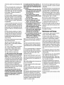
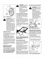
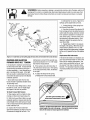
Decals
Reverse Clutch Control
OperatingInstruction
(Models 634F/634B)
ForwardClutchBail
For your safety and the safety of others, various safety and operationa! decals are located
on your unit (see Figure 1-2).
Keepthe decals clean and legible at all times.
Contactyour local service dealer or the factory
for replacements if any decals are damagedor
missing.
StartingStabilization
Message(onengine)
WarningMessages
Referto the Parts List pagesin this Manual for
decal locations, descriptions and part numbers.
Hot SurfacesWarning
Figure 1-2: Locationof safely and operatingdecals (5,5 HP Model shown),
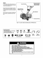
OperatingSymbols
Var_us_bds(shown
here,
w_hworddesk)
maybeused
onthe_llera_d
engine.
NOTFz
Yeur_n'_r_thavealid_symb_.
I-'-I ltl
CHOKE
ON
CHOKE
OFF
R
REVERSE
ROTATING
_
TINES
,K÷
FAST
SLOW
STOP
TILLERDIRECTION
ENOAOE.
BAIL
LEVERDIRECTION
TO AVOIO SERIOUS INJURY:
READTHE OWNER'SMANUAL.
KNOWLOCATIONSAND FUNCTIONSOF ALLCONTROLS.
KEEPALLSAFETYDEVICESANDSHIELDSIN PLACEAND WORKING.
NEVERALLOWCHILDRENOR UNINSTRUCTEDADULTSTO OPERATETILLER.
SHUTOFF ENGINEANDDISCONNECTSPARKPLUGWIRE BEFOREMANUALLYUN"
CLOGGINGTINES OR MAKINGREPAIRS.
• KEEPBYSTANDERSAWAYFROM MACHINE.
• KEEPAWAYFROMROTATINGPARTS.
• USEEXTREMECAUTIONWHEN REVERSINGOR PULLINGTHEMACHINETOWARDS
YOU.
•
•
•
•
•
BAIL
DISENGAGED
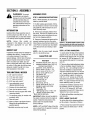
SECTION2: ASSEMBLY
WARNING:
To prevent
personal injury or property
damage,do not start the engine
until all assembly steps are
complete and you have read
and understandthe safety and
operating instructions in this
manual.
INTRODUCTION
Carefullyfollow these assembly steps to
correctly prepare your tiller for use. It _s
recommended that you read this Section
in its entirety before beginning assembly.
NOTE:
Various
tiller
models
are
presented in this Manual. Use only the
information appropriate for your tiller
model,
INSPECTUNIT
Inspectthe unit and carton for damage tmmediately after delivery. Contact the carrier (trucking company) if you find or
suspect damage. Inform them of the damage and request instructions for filing a
claim. To protect your rights, put your
claim in writing and mail a copy to the carrier within 15 days after the unit has been
delivered. Contact Troy-Bilt LLC it you
need assistance in this matter.
TOOLSMATERIALS
NEEDED
(11 3_8"open-end wrench(2) 7/16"open-end wrench(.2_ 1/2" open-end wrench*
(.2_ 946"open-end wrench(1) Large ad Jstable wrench
_Models634F/634B only)
(.11 Scissors totrim plastic ties
(1) Ruler (for belt tension check_
Ill Block of wood (to support tiller when
removing wheels)
(1) Tire pressure gauge _for models with
pneumatic tires_
111 Cleanoil funnel
Ill
Motor oil Referto the EngineOwner's
Manualfor oil specificationsand
quantityrequired.
* Adlustable wrenches may Deused.
ASSEMBLYSTEPS
STEP 1: UNPACKING INSTRUCTIONS
m
NOTE: While unpackin0, do not severely
bend any control cables.
1. Thetiller weighs approximately 133 lbs.
Do not attempt to remove it from the shipping platform until instructed to do so in
these Assembly steps.
2. Removeany packaging material from
the carton. Removeany staples from the
bottom of the carton and remove the carton from the shipping platform.
3. Removeall unassembled parts and the
separate hardware bag from the carton.
Checkthat you havethe items listed in the
LoosePartsList(contactyourlocaldealer
orthe factory items are missing or damaged).
NOTE: Use the screw length template
(Fig. 2-1) to identify screws
LoosePartsList
Qty.
Description
1
HandlebarSupport (seeA, Fig. 2-2_
1
HandlebarAssembly(see K, Fig.2-2)
Hardware bag contents:
1
Slotted hd. screw #10-24 x 2'
1
Hex bd. screw 1/4-20 x 1-1/4
6
Hex hd. screw 5/16-18x 1-1 2"
2
Hex hd. screw. 3/8-16 x 3/4
2
Flat Washer.3/8°
6
Split Iockwashe_ 5/16_
1
Hex Iocknut. 1/4"-20
8
Hex nut. 5/16"-18
1
Hex nut #10-24
2
Hex Iocknut. 3_8"-16
1
Spring, cable (see W, Fig. 2-5'_
1
Bracket. forward clutch cable
(see P, Fig. 2-4_
2
Lockwasher 3/8
2
*Self-tapping screw. 1/4-20 x 1/2
1
*Bracket reverse clutch cable
Model 634F & 634B only
IMPORTANT: Motor oil must be added to
the engine crankcase before the engine is
started. Follow the instructions in this
Section and in the separate Engine
Owner's Manual.
NOTE:LEFTandRIGHTsidesofthetiller
are as viewed from the operator's position
behind the handlebars.
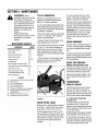
Figure2-1: Toidentify lengthofscrews,place
screwon templateasshownandmeasuredistancebetweenbottomofscrewheadandtipof
screw,
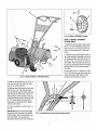
STEP 2: ATTACH HANDLEBAR
1. Loosely attach the legs of the handlebar
support (A, Fig. 2-2) to the inner sides of
the tiller frame using two 3/8"-16 x 3/4"hex
hd. screws (B), 3/8" flat washers (C), 3/8"
lock washers (GG',and 3/8"-16 hex locknuts (D',
2. Thereare three height adjustment holes
in the two handlebarsupport brackets (.E
and E Fig. 2-2). Use a setting that will position the handlebarsat approximately
waist levelwhen the tines are 3"-4" into the
soil. Loosely attach the support brackets
to the handlebar support (.A_using two
5/16"-18x 1-1/2" screws (G), 5/16" split
Iockwashers (.H)and 5/16"-18 hexnuts [I).
NOTE: If a support bracket will not move
loosen attaching screw (J) and nut.
3. Attach the handlebar assembty (.K_to
the handlebar supporl (A) using four 5.
16"-18 x 1-1/2" screws (.G_,5/16" split
Iockwashers (H) and 5/16"-18 hexnuts (I).
Tighten the four screws securely
4. Tighten all handlebar mounting hardware securely.
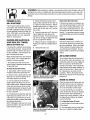
STEP 3: MOVE TILLER OFF
To roll the tiller off the shipping platform.
put the wheels in freewhee as follows:
1. Placea sturdy block under the transmission to raise one wheelabout 1" off the
ground.
Fig. 2=3: Wheel in FREEWHEELposition
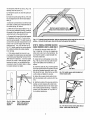
STEP 4: INSTALL FORWARD
CLUTCH CABLE
1. Attach the forward clutch cable bracket
(P, Fig. 2-4) to the handlebar support AI
with a 1/4"-20 x 1-1/4" hex hd. screw (R)
and 1/4"-20 hex Iocknut (S). Tighten securely.
2. Carefully unwrap the forward clutch cable (cable without an attached knob, from
its shipping position and slide the thin cable wire (T, Fig. 2-4) into the slot in the cable bracket. Push the cable connector (U,
Fig. 2-4) up through the hole in the bracket
until the groove in the connector snaps
into place.
3. Insert the #10-24 x 2" slotted hd. screw
(V, Fig. 2-5) down through the hookedend
Fig.2.2: Atlachhandlebar(5.5 HpMOde!shown),
of the cable spring (W) until the screw
threads extend thr0ugh the spring.
2. Removethe hairpin cotter (L, Fig. 2-3)
and wheel drive pin (M) from the wheel
hub (0) and wheel shaft (N).
3. Slidethe wheelfully inward on the wheel
shaft (N, Fig. 2-3). Reinstall the wheel
drive pin (M) through the wheel shaft only
(not through the wheel hub). Securethe
wheel drive pin with the hairpin cotter (L),
pushing the hairpin cotter in asfar as it will
go. The wheel should now spin freely
(freewheel) on the wheel shaft. Repeat
with the other wheel.
4. Usethe handlebarto roll the tiller to a
flat area.
IMPORTANT: Before Starting the engine,
the wheels must be placedin the WHEEL
DRIVEposition (pins through wheel hubs
and wheel shaft). This procedure is
described in WheelDrive Pins in Section 3.
Fig.2-4. Installingforwardclutchcablebracketandcable.
4.Thread
the#10-24 hex nut (Z, Fig. 2-5)
halfway onto the screw (V).
5. Thread the screw IVI into the cable adjuster (X).
6. Hook the cable spring (W, Fig.2-6) into
the V-shaped bend in the Forward Clutch
Bail
7. Checkfor correct tension on the forward
drive belt by taking two measurements of
the cable spring, as follows:
a. With the Forward Clutch Bail (Y, Fig. 26/in an open (released) position, measure
the length of the cable spring (W from the
outermost coil to the outermost coil.
D. Squeezethe Forward Clutch Bail against
the handlebar (see Fig. 2-7_ and re-measure the spring length, The belt tension is
correct if this second measurement is between 1/16"to 34 6" longer than the first
measurement. If so. turn the hex nut (Z.
Fig.2-7) tightly against the cable adjuster
(X_while preventing the cable adjuster
from turnmg.
c. If the spring length is incorrect, you
must adjust the cable tension as described
in Checkingand Adjustin_ Forward Drive
Belt Tensionin Section 5. Incorrect cable
tension can result in belt slippage Icable
tension too IooseJ.or unintentional tine
movement when the clutch bail is in Neutral _cabletension too tight}
Fig. 2- 7: Tocheckforwardbelt tension, lake two measurementsof the length of the coilsin the
spring- first with the bail open, then with the bail held against the handlebar,
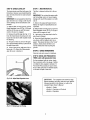
STEP 5: INSTALL REVERSE CLUTCH
CABLE (MODELS 634F & 634B ONLY)
1. Unwrap the reverse clutch cable (CC.
Fig. 2-8 and Fig. 2-9_from its shipping position and route it up to the handlebar. Be
sure that the cable is routed beneaththe
Forward Clutch Bail.
2. Using the two self-tapping screws (AA,
Fig. 2-8) secure the reverse cable mounting bracket (BB)to the handlebars as
show_
3. Insertthe cable(CC,Fig.2-8) through the
slotin the cablebracketand position the flat
side ofthe threadedassembly next to the
flat side ofthe hole. Slide the hex nut (DD/
up the cableand tighten it securely.
CC
Fig. 2-8: Install reverse cable bracketand
reverseclutch cable,
4. Fastenthe reverse clutchcableto the
leftsidehandlebar witha cabletie (EE,Fi_
2-9L
Wm
5. Testthe function of the reverseclutch by
pulling out and releasing the cable knob.
The knob should return to its neutral position (resting against bracketL If it doesn't.
contact your local dealer or Troy-Bilt LLC
for technical assistance.
Zm
X--
Fig. 2-5: Cable
springand
adjuster.
Fig. 2-6:Attachforward
clutch cablespringto
forwardclutchbail.
Fig, 2-9: Route reverseclutch cable (CC) as
shown, Attach with cable tie (EE).
31bY I_: UI'IEUK LEVEL UI-
_IbY
Thetransmission was filled with gear oil at
the factory. However,you should checkthe
gear oil level at this time to makecertain it
is correct.
Thetiller is shipped withoutoil in the engine.
IMPORTANT:Do not operatethe tiller if the
gear oil level is low. Doing so will result in
severe damageto the transmission components.
1. With the tiller on level ground, pull the
Depth Regulator Lever (FF,Fig. 2-10) back
and then all the way up until the lowest
notch in the lever is engaged.
2. Removethe oil fill plug (GG, Fig. 2-11)
from the transmission housing cover and
locate the main drive shaft situated inside
the housing.
3. The gear oil level is correct if the gear
oil is approximately halfway up the side of
the main drive shaft.
4. If the oil level is low, add gear oil by referring to A. ToCheckthe Transmission
GearOil Level in Section 5.
I: AUU MUIUH
UIL
IMPORTANT:Do not start the engine without first adding motor oil. Severeengine
damagewill result if the engine is run without oil.
1. Refer to the separate Engine Owner's
Manual for engine oil specifications and
capacities.
2. With the tiller on levelground, move the
Depth Regulator Lever(FF,Fig. 2-10) up or
down until the engine is level.
3. Add motor oil as described in the Engine Owner's Manual.
4. Move the Depth Regulator Leverall the
way down until the highest notch is engaged. This places the tines in the "travel"
position, which allows the tiller to be
moved without the tines touching the
ground.
STEP8: CHECKHARDWARE
Checkall nuts and screws for tightness.
STEP 9: CHECK AIR PRESSURE IN
TIRES (units with pneumatic tires)
On tires equipped with air valves, check
the air pressure with a tire gauge. Deflate
or inflate the tires equally to between 15
PSI and 20 PSI (pounds per square inch).
Be sure that both tires are inflated equally
or the unit will pull to one side.
Fig. 2-10: AdjustDepth RegulatorLever.
._ru.l_N i: his compie_esme assemoiy steps.
Before operating your tiller, make sure you read the
{ollowingsections in this Manual, as well as the
separate Engine Owner's Manual:
• Section 1: Safety
• Section 3: Featuresand Controls
• Section 4: Operation
Fig.2-11: Removegearoil fill plug.
SECTION3: FEATURES
ANDCONTROLS
WARNING:
Before
operating your machine,
carefully readand understand
all safety, controls and
operating instructions in this
Manual, the separateEngine
Owner's Manual,and on the
decals on the machine.
Failureto follow these
instructions can result in
serious personal injury.
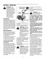
Forward
(Models634F/634B)
DepthRegulator
INTRODUCTION
This Section describes the location and
function of the controls on your tiller. Refer to the following Section, Operationfor
detailed operating instructions.
Handlebar Height Adjustment
Practice using these controls, with the engine shut off, until you understand the operation of the controls and feel confident
with each of them.
ENGINE CONTROLS
Refer to the engine manufacturer's Engine
Owner's Manual (included in the tiller literature package)to identify the controls on
your engine.
IMPORTANT:Thecontrol for stopping the
engine is located on the engine.
WHEEL DRIVE PINS
Eachwheel is equipped with a wheel drive
pin (A, Figures 3-2 and 3-3) that secures
the wheel to the wheel shaft (B). The
wheels can be positioned in either a
WHEELDRIVEora FREEWHEELmode.
WARNING:
Neverallow
either of the wheels to be in the
FREEWHEELposition when the
engine is running. Always put
both wheels in the WHEEL
DRIVEposition beforestarting
the engine.
Failureto comply could cause
loss of tiller control, property
damage, or personal injury.
Beforestarting the engine,put both wheels
in the WHEELDRIVEposition by inserting
the wheel drive pins through the wheel
hubs and the wheel shaft. Doing so
"locks" the wheels to the wheel shaft,
causing the wheels to turn when either the
Reverse ClutchControl
Wheel Drive Pin
(oneachwheel)
Figure3-1: Tillerfeaturesandcontrols(5. HPModelshown). SeeS_eparate
EngineOwner's
Manual toidentifyenginecontrols.
Forward Clutch Bail (all models) or the Reverse Clutch Control (Models 634F and
634B) is engaged.
Use the FREEWHEELmode only when the
engine is not running. In FREEWHEEL,
the
wheel drive pins are placed only through
the holes in the wheel shaft (not the wheel
hubs), thus allowing the wheels to turn
freely when you manually move the tiller.
To place the wheels in WHEELDRIVEor
FREEWHEEL:
1. Stop engine,disconnect spark plug wire
from spark plug and allow engineto cool.
_
tillerARNING:
on its side when
changing
Do not
place
wheeldrive positions. Doing so
could result in gasoline leaking
from the fuel tank.
Failureto follow this instruction
could result in personal injury
or property damage.
2. Raise one wheel about one inch off the
ground and placea sturdy support under
the transmission.
3. Removehairpin cotter (C, Figures 3-2
and 3-3) from wheel drive pin (A).
4. FORWHEELDRIVEMODE(Figure3-2):
Slide wheel outward and align holes in
10
Figure3-2: WHEELDRIVE position.
wheel hub (D, Figure 3-2) and wheel
shaft (B). Insert wheel drive pin (A)
through wheel hub (D) and wheel
shaft (B). Securewheel drive pin with hairpin cotter (C) by pushing hairpin cotter in
as far as it will go. Repeatwith the other
wheeland then remove the support from
beneaththe transmission.
5. FORFREEWHEEL
MODE ( Figure3-3):
Slide the wheel inwardand insert the wheel
drive pin (A, Figure3-3) only through the
hole in the wheel shaft (B). Secure wheel
drive pin with hairpin cotter (C) by pushing
hairpin cotter in as far as it will go. Repeat
for the other wheel and then remove the
support from beneaththe transmission.
WARNING:
Use extreme
caution when reversing or
pulling the machine towards
you. Look behind to avoid
obstacles.
Neverattempt to till in reverse.
Failureto follow this warning
could result in personal injury
or property damage.
To operatethe Reverse ClutchControl:
1. Put wheels in WHEELDRIVEposition
(see "WARNING" statement at the left).
Figure 3-3: FREEWHEELposition.
_,
2. Stop all tiller motion by releasing the
Forward Clutch Bail.
engine,
be sure that
both
WARNING:
Beforestarting
wheels are in WHEELDRIVE
position. See Whesl Drive Pins
for instructions,
the
ground,
look behind
avoid
any
3. Lift
the handlebar
untilyou
theto
tines
clear
obstacles, and then pull the control knob
(F, Figure3-4) out. The wheels and tines
will rotate in a reverse direction.
Engaging the Forward Clutch
Bail or ReverseClutch Control
(if equipped) when the wheels
are not inWHEELDRIVEcould
allow the tines to rapidly propel
the tiller forward or backward.
Failureto comply could cause
loss of tiller control, property
damage, or personal injury.
4. Releasethe control knob to disengage
(stop) the wheels and tines (the engine will
continue to run).
begin tilling at a very shallow depth setting
and gradually increasethe tilling depth.
WARNING:
Do not attempt
to till too deeply too quickly.
Graduallywork down to deeper
tilling depths.
Placethe Depth Regulator
Lever in the "travel" position
before starting the engine. This
position preventsthe tines from
touching the ground until you
are ready to begin tilling.
Failureto follow this warning
could result in personal injury
or property damage.
Figure3-5: Depth RegulatorLever (GJ.
HANDLEBAR HEIGHT ADJUSTMENT
Thehandlebar height is adjustable to three
different settings (Figure 3-6). In general,
adjust the handlebars so they are at waist
level when the tines are 3"-4"in the soil.
FORWARDCLUTCHBAIL
Th Forward Clutch Bail (E, Figure3-4) controls the engagement of forward drive to
the wheels and tines.
Toadjust the handlebars:
To operatethe ForwardClutch Bail:
1. Put wheels in WHEELDRIVEposition
(see "WARNING" statement above).
Figure3-4:AIImodelshavea ForwardClutch
Bail (E). OnlyModels634F/g34B
havea Re,
1. Stop engine, disconnect spark plug
wire from spark plug and allow engine to
cool.
2. Lift and hold the clutch bail (E, Figure 34)againstthehandlebartostartthewheels
and tines rotating in a forward direction.
DEPTH REGULATOR LEVER
2. Remove hardware, reposition handlebars, and reinstall hardware securely.
verse Clutch Control(F).
3. Releasethe clutch bail to disengage
(stop) the wheels and tines (the engine will
continue to run).
This lever (G, Figure3-5) controls the tilling depth of the tines. Pull the lever back
and slide it up or down to engagethe
notched height settings.
REVERSECLUTCHCONTROL
The"travel position" (highest notch) raises
(Models 634F/634B only)
the tines approximately 1-1/2" off the
ground, allowing the tiller to be moved
without the tines contacting the ground.
This setting should also be used when
starting the engine.
The ReverseClutch Control (F,Figure 3-4)
controls the engagement of reverse drive
to the wheels and tines. The reversing
feature is usedfor maneuveringthe tiller
only-- never engage the tines in the
groundwhile operatingin reverse,
Moving the lever upward will increase the
tilling depth. Thelowest notch allows a tilling depth of approximately 6", depending
on soil conditions. For best results, always
11
Figure3-6: Handlebarheightadjustment.
SECTION4: OPERATION
WARNING:
Before
operating your machine,
carefully readand understand
all safety (Section 1), controls
(Section 3) and operating
instructions (Section 4) in this
Manual, the separate Engine
Owner's Manual,and on the
decals on the machine.
Failureto follow these
instructions can result in
serious personal injury.
1. Complete the Pre-Start Checklist on
this page.
ReverseClutchControl
(Models634F/634B)
2. Putthe wheels in the WHEELDRIVEposition (see WheeIDrive Pins in Section 3 of
this manual).
Clutch
_
Bail
INTRODUCTION
Readthis OperationSection and the separate EngineOwner's Manual before you
start the engine. Then, take the time to familiarize yourself with the basic operation
of the tiller before using it in the garden.
Findan open, levelarea and practice using
the tiller controls without the tines engaging the soil (put tines in "travel" setting).
Only after you've become completely familiar with the tiller should you begin using
it in the garden.
BREAK-INOPERATION
Perform the following maintenanceafter
the first two (2) hours of new operation
(see Maintenance Section in this manual
and in the Engine Owner's Manual).
1. Changeengine oil.
2. Checkfor loose or missing hardwareon
unit. Tighten or replace as needed.
3. Checktension on forward drive belt.
4. Checktransmission gear oil level.
STARTINGANDSTOPPING
Pre-StartChecklist
With the spark plug wire disconnected
from the spark plug, perform thefollowing
checks and services before each use:
1. Readthe Safetyand Controls Sections
in this manual. Readthe separate Engine
Owner's Manual provided with the unit.
2. Put the wheels in the WHEEL DRIVE
position (wheel pins must be through
holes in wheel hubs and wheel shaft).
3. Check unit for loose or missing hardware. Service as required.
4. Checkengine oil level. See Engine
Owner's Manual.
Pin
Fig.4-1
5. Checkthat all safety guards and covers
are in place.
6. Checkair cleaner and engine cooling
system. See Engine Owner's Manual.
WARNING:
GASOLINEIS
HIGHLYFLAMMABLEAND ITS
VAPORSAREEXPLOSIVE.
Follow gasolinesafety rules in
this Manual (see Section 1) and
in the separateEngine Owner's
Manual.
Failureto follow gasolinesafety
instructions can result in
serious personal injury and
property damage.
7. Fillthe fuel tank with gasolineaccording
to the directions in the separate Engine
Owner's Manual. Follow all instructions
and safety rules carefully.
8. Attach spark plug wire to spark plug.
Startingthe Engine
Thefollowing steps describe how to start
and stop the engine.
WARNING:
Do not attempt
to engagethe tines or wheels
until you haveread all of the
operating instructions in this
Section. Also, review the safety
rules in Section 1: Safety,and
the tiller and engine controls
information in Section 3:
Featuresand Controls.
prevent
serious personal
ARNING:
To help injury
or damageto equipment:
• Beforestarting engine, putbothwheels
in the WHEEL DRIVE position. Never
have wheels in FREEWHEELposition
when engine is running. When the
wheels are in FREEWHEEL,they do not
hold back the tiller and the tines could
propelthe tiller rapidly
ward or backward.
• Before starting engine, put Forward
Clutch Bail (all models) and Reverse
Clutch Control (Models 634F/634B only)
in neutral (disengaged) positionsby releasing levers.
• Never run engine indoors or in enclosed, poorly ventilated areas. Engine
exhaust contains carbon monoxide, an
odorlessand deadlygas.
• Avoidengine mufflerand nearbyareas.
Temperaturesin theseareas may exceed
150oF.
3. Move the Depth Regulator Lever all the
way down to the "travel" position, so that
the tines clear the ground.
4. Releaseall controls on the tiller.
5. On engine'swith a fuel shut-off valve,
turn valve to open position, as instructed
in the separate Engine Owner's Manual.
6. Put ignition switch and/or throttle control lever located on engine in the "ON",
"RUN", "FAST"or "START"position, as instructed in the Engine Owner's Manual.
7. Chokeor prime engine,as instructed in
Engine Owner's Manual.
8. Put one hand on fuel tank to stabilize
unit when pulling starter rope handle.
Then use recoil starter to start engine,as
instructed in the EngineOwner's Manual.
Whenengine starts, gradually move choke
lever (if so equipped) to "NO CHOKE",
"CHOKEOFF"or "RUN" position.
9. Use the "FAST"throttle speed setting
when tilling.
12
4. For forwardmotion of the wheels and
tines:
(a) Pull Forward Clutch Bail (Fig. 4-1) up
against handlebar. Releasebail to stop forward motion of wheels and tines.
KEEP
AWAYF_OMROTATING
11NES.
ROTATING
11NE$WILLCAUSE
INJURY.
Stoppingthe Engineand Tiller
1. Tostop the wheels and tines, releasethe
Forward Clutch Bail (all models) or the Reverse Clutch Control (Models 634F and
634B) -- whichever control is in use.
2. To stop the engine, put the ignition
switch and/or the throttle control lever in
the "OFF"or "STOP" position.
OPERATINGTHE TILLER
Thefollowing operating instructions provide guidelines to using your tiller effectively and safely. Be sure to read Tilling
Tips & Techniques in this Section before
actually putting the tines into the soil.
NOTE:This isa traditional "Standard-Rotating-Tine" (SRT) tiller with forward rotating tines. It operates completely
differently from "Counter-Rotating-Tine"
(CRT)tillers or from front-tine tillers.
1. Follow the Pre-Start Checklist at the
beginning of this Section. Besure that the
wheels are in the WHEEL DRIVEposition.
2. Move the Depth Regulator Leverall the
way down, so that the tines clear the
ground. Usethis position when practicing
with the tiller and when traveling between
tilling sites. Before actually tilling, move
the lever to the desired depth setting (see
Tilling Tips & Techniques).
3. Start engine and allow itto warm up.
Then put throttle in "FAST"setting.
(b) When tilling, relax and let the wheels
pull the unit while the tines dig. Walk behind and a little to one side of the unit. Use
one hand, yet keepa light--but secure-grip on the handlebar (while keeping your
arm loose). See Fig. 4-2. Let the unit
move at its own paceand do not push
down on the handlebarsto try and force
the tines to dig deeper --this takes weight
off the wheels, reduces traction, and causes the tines to try and propel the tiller.
WARNING:
Do not push
down on the handlebarsto try
to make the tiller till more
deeply. This preventsthe
wheels from holding the tiller
back and canallow the tines to
rapidly propel the tiller forward,
which could result in loss of
control, property damage, or
personal injury.
5. For reverse motion of the wheels and
tines (Models 634F/634B only):
(a) Look behind and exercisecaution when
operating in reverse. Do not till while in
reverse.
(b) Swing the handlebarto the left so the
right wheel takesa "step" backward. Next
swing the handlebarto the right so the left
wheel"steps" backward. Repeatas needed.
(c) If longer distances need to be covered
in reverse,shut off the engine, then place
the two wheels in FREEWHEEL.
7. To Turn the Tiller Around:
(a) Practice turning the tiller in a level,
open area. Be very careful to keepyour
feet and legs away from the tines.
(b) To begina turn, lift the handlebarsuntil
thetinesare out ofthe groundand theengine
andtines are balancedoverthe wheels (Fig.
4-4).
(c) With tiller balanced, push sideways on
handlebar to steer in direction of turn (Fig.
4-5). After turning, slowly lower tines into
soil to resume tilling.
Fig.4_4: Tobeginturn,lift handlebars
until
tinesareoutofgroundandunitis balanced.
(b) Stop all forward motion. Lift handlebar with one hand until tines are off the
ground and then pull Reverse Clutch Control knob out (seeFig. 4-3). To stop reversing, let go of ReverseClutch Control knob.
Fig.4-5: Withtinesoutofground,pushhandlebarssidewaysto turntiller.
Fig. 4-3: Raisetinesoffgroundandlook
behindwhenmovinginreverse.
6. To move the Model 630C in reversefor
short distances:
Fig.4-2: Useonehandtoguidetiller when
movingforward.
(a) Releaseforward Clutch Bail. Then lift
handlebaruntil tines are off the ground.
13
StoppingtheTillerandEngine
1. To stop the wheels and tines, release
the Forward Clutch Bail (all models) or the
ReverseClutch Control (Models 634F and
634B) -- whichever control is in use.
2. To stop the engine, put the ignition
switch and/or the throttle control lever in
the "OFF"or "STOP" position.
TILLING
Tilling Depths
_=i,
A L•
m, m.
WARNING:
Before
tilling, Contactyour
telephone or utilities
company and inquire if
underground equipment or
lines are used on your
property. Do not till near
buried electric cables,
telephone lines, pipes or
hoses.
TIPS & TECHNIQUES
• Avoid pushingdown on thehandlebarsin an attemptto force the tillerto dig deeper•Doing
so takesthe weight off the poweredwheels,causingthem to losetraction•Without the wheels
helpingto hold the tiller back,the tines will attemptto propelthe tiller - often causingthe tiller
to skip rapidly acrossthe ground• (Sometimes,slight downward pressureon the handlebars
will helpgetthrough a particularlytough sectionof sodor unbrokenground,but in most cases
this won't be necessary.)
• Avoidtrying to dig too deeplytoo quickly,especiallywhenbusting sod or when tilling soil
that hasn'tbeentilled for sometime• Useshallowdepth regulatorsettings (onlyan inch or two
deep)for the first passesthrough the soil• With eachsucceedingpass,dig anotherinch or two
deeper•(Wateringthe areaa few days prior to tilling will maketilling easier,as will letting the
newlyworked soil set for a dayor two beforemakinga final, deeptilling pass.)
• Whencultivating (breakingup surfacesoil around plantsto destroyweeds,seeFig.4-9), adjust thetinesto dig only 1"to 2"deep• Using
shallowtilling depthshelpspreventinjury to plantswhose rootsoften grow closeto the surface. If needed,lift up on the handlebarsslightly
to preventthe tines from digging too deeply. (Cultivatingon a regular basis not only eliminatesweeds,it also !oosensandaeratesthe soil
for better moistureabsorptionand faster plantgrowth•)
ChoosingCorrectWheel &Tine Speeds With experience,you will find the "just right" tillingdepth and tillingspeedcombination
that is best for your garden•
Setthe enginethrottle leverat a speedto give the engineadequatepowerand yet allow it to operateat the slowest possiblespeed...atleast
until you haveachievedthe maximumtilling depthyou desire. Fasterenginespeeds may be desirablewhen makingfinal passesthrough
the seedbedor whencultivating•Selectionof the correct enginespeed,in relationto the tilling depth,will ensurea sufficient power levelto
do the jobwithout causingthe engineto labor.
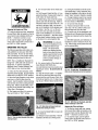
Let theTiller Dothe Work
Whiletilling,relaxand letthewheels puII the
tiller along while the tines do the digging•
Walk on the sidethat is not yet finished (to
avoid makingfootprints in the freshly tilled
soil) and lightly, but securelygrip the handlebarwith just one hand,
AvoidMakingFootprints
AvoidTilling Soggy,Wet Soil
Wheneverpossible, walk on the untilled Tilling wet soil often results in large, hard
side of the unitto avoidmaking footprints in clumps of soil that can interfere with plantyour freshly tilled or cultivated soil• Foot- ing. If time permits, wait a day or two after
printscausesoil compactionthat can ham- heavy rains to allow the soil to dry before
per root penetration and contribute to soil tilling• Testsoil by squeezingit intoa ball. If
erosion. They can also !'plant" unwanted it compressestoo easily,it is too wet to till.
weed seeds back into the freshly tilled
ground•
PreparingSeedbeds
• When preparing a seedbed,go over the same pathtwice in the first row, then
overlapone-half the tiller width on the rest of the passes(see Fig.6). When finishedin one direction, makea second passat a right angle,as shown in Fig.4-7.
Overlapeach passfor best results (in very hard ground, it may take three or four
passesto thoroughlypulverizethe soil.)
Fig. 4-6
Fig. 4-7
Cultivating
• Ifthegardensizewillnotpermitlengthwiseandthencrosswisetilling thenoverlapthefirst
tiller.
passesbyone-halfa
.
width,followed bysuccessivepasses
at one-quarterwidth"(seeE'g 4-8)
........... _
..................
............
'
Fig.4-8
With nlanninn ,,ou can _,_v_,
_r_
aIIow e_n
oughr'oo_m
_- _) " _ "-(_ "
betweenrows to Cut vate _
_
,_
_'
_
tsee rig. ,4-u).Leaveroom ¢2,._ @ #_
•
_
_._ t,.2j
' for the hood width, ._,
_,-_,
_
'
plus enough extra _
4_',,
_11
room for future plant
growth.
14
Fig. 4-9
TILLING
TIPS& TECHNIQUES
(CON'T)
PowerComposting
Powercomposting simply meanstillingunderand burying in thesoil all mannerof organic
mattersuch as crop residues,leaves,grassclippings and cover crops. This materialwill decomposeduring the non-growingseasonand add importantnaturalnutrientsto the SO
WARNING:
When power
composting, do not keepthe
Depth Regulator Leverat a
Thefirst placeto beginis with crop residuessuch asleftovervines,stalks,stemsand roots,
Powercompost these crop residuesas soon asthey finish bearing.Thesoonerthis isdone,
the better,astendergreen matter is easierto till under. Usethe deepestdepth regulatorsetting possiblewithout causingthe engineto labor or the tiller to jump ahead,
deep setting if the tiller jumps
or bucks.
If jumping or bucking occurs,
move the Depth Regulator
Leverdown to a shallow
setting and then slowly
Standingcornstalksof reasonableheight can be powercomposted.Pushing over (but not
uprooting) cornstalkswill often make it easierto chop up the stalks.Keepthe tines clearof
excessivetangling by ,fishtailing"or frequentlyusing reverse.Make severalPaSSeS,
then re-
increasethe tilling depth or}
later passes.
^:,..... ,^,,^. ,,._..... :__
turn a few days ater to f n sh off any reman ng stubb e
FaHu_uLU/UIIUW
Aftertilling undercrop residues,add moreorganicmattersuch asleaves,grassclippings and
evenkitchenscraps. Whentilled intothe soil, this organicmatterwill decomposeand add
evenmore important nutrientsto the soil.
tl I1:_ W_/llllly
could result in personal injury.
After powercomposting,you may want to planta "greenmanure"cover crop to protectthe soil during the off-season. Yousimply grow a
crop of clover,alfalfa, buckwheat,peas,beans,ryegrass, grain,or kaleandthen till it into the soil prior to the plantingseason.
Tilling OnSlopes
Readthe following recommendati_ns beforetilling on slopes:
/%
If you must gardenon a moderateslope, pleasefollow two very _mportantgmdelmes:
1. Til! only on moderatemodes,neveron steepgroundwherefooting s difficult ! "eviewsafery rules {nSection ]: Safetyof this manuai).
2. We recommendtilling up an{] clownslopes ratherthan terracing. Tilling vertically on a
slopeallows max{mutt plantingareaand also leavesroom for cultivating.
IMPORTANT:Whentilling on slopes be surethe correct oil levelis maintainedin the engine
checkevery one-halfhour of oDerat!on_.The inclineof the slopewl causerne m to slant
awayfrom its normal leveland this canstarve enginepartsof requiredlubrication. Keeothe
motor oH_evmat the full point at a!l times!
WARNING:
Do not
operatetiller on a slope too
steel_for safe operation. Till
slowly and be sure you have
good footing. Never permit
tiller to freewheel down
slopes. Failureto followthis
warning could result in
personal injury.
Tilling Up and DownSlopes [Vertical Tilling)
• To keepsoil erosionto a minimum, besureto add enough organicmaker re rne SOilso that d hasgood moisture-holdingtextureandtry
to avoid leavingfootprints or wheelmarks.
• Whentilling vertically,try to makethe first pass. _hillas the tiller digs moredeeplygoing uphill than it does downnm. In soft soil or
weees,you may haveto lift the handlebarssbghtlywhile going uphill. When going downhill, overlapthe first pass byabout one-halfthe
width of the tiller.
Tilling AcrossSlopesWithout UsingTerraces(HorizontalTilling)
• f vertical or terracing gardeningaren't practicalfor you, then you cantill laterallyacrossa slope. We don't recommendthis methodas
t can createunsurefooting and invitessoil erosion.
• As in terracegardemng,startat thetop of the slopeand overlapthe first passey _alfthe width of thetiller. Foraddedstabilityof the tiller.
alwayskeepthe uphill wheelin the soft. new_ytilled so_l.
Terrace Gardening
• Whena slope_stoo steep or too short for verticaltilling, It may be necessaryto t_llacrossthe slope and createterraced rows.Terraces
are rows that are cut rotethe sideof a slope,creating a narrow, but flat areaon which to plant.
• Ona long s_ope,you can makeseveralterraces,one belowthe other.
• Terracesshouldbeonly 2-to-3 feetwide. Diggingtoo far intothe sideof the slopewil! exposepoor subsoilthat is unproductivefor plants.
15
TILLING
TIPS& TECHNIQUES
(CON'T)
TerraceGardening(continued)
• Tocreatea terrace,startat the top of the slopeand work down.Go backand forth
acrossthe first r0was shown in Fig.4-!0.
• Eachsucceedinglowerterraceisstartedbywalkingbelowtheterraceyou'repre0_11_1__..,..___,_,,.
paring. Foraddedstability of thetiller, alwayskeepthe uphill wheelin the soft, newly tilled soil. Do not till the last 12"or more of the downhill outside edge of each
_1_
terrace. This untilled strip helps preventsthe terracesfrom breaking apart and
__
ClearingtheTines
Thetines havea self-clearingaction which eliminatesmost tangling of debris in
thetines. However,occasionallydry grass,stringy stalksor tough vines may become tangled. Followthese proceduresto help avoid tangling and to cleanthe
tines, if necessary.
• To reducetangling, set the depth regulator deep enough to get maximum
"chopping" action asthe tines chop the materialagainstthe ground. Also, try to
till under crop residuesor cover crops while they are green,moist and tender.
• It maybe necessaryto removethe debrisby hand
(a pocketknife will help you to cut awaythe material). Besure to stop the engineand disconnectthe
spark plug wire beforeclearingthe tines by hand.
_lb
• While powercomposting,try swayingthe handlebarsfrom sideto side (about
6"to 12"). This 'ffishtailing"action often clearsthe tines of debris.
• If tanglingoccurs, lift the tines out of the soiland run thetiller in reverse(if unit
is equippedwith poweredreverse) for a few feet. This reversing action should
unwinda good deal of debris.
LOADINGAND UNLOADING
THETILLER
A
clearing
tines
by hand, Stopthe
WARNING:
Beforeengine,allow
the
all moving parts to stop and
disconnect the spark plug wire.
Removethe ignition key on electric
start models.
Failureto follow this warning could
result
in personal injury.
• Use sturdy ramps and manually (engine
shut off) roll the tiller into and out of the
tiller ahead of you. Have a Personat each
side to turn the wheels.
vehicle. Two or more peopleare neededto
* When going down ramps, walk back
WARNING:
Loadingand
Unloadingthe tiller into a
vehicle is potentially hazardous
and we don't recommend doing
so unless absolutely necessary,
asthis could result in personal
_othis,
The ramps must be strong enough to
support the combined weight of the tiller
and any handlers. The ramps should provide good traction to prevent slipping; they
should have side rails to guide the tiller
wardwiththetillerfollowingyou.
Keep
alert for any obstacles behind you. Position a person at each wheelto control the
speed of the tiller. Nevergo down ramps
tiller-first, as the tiller could tip forward.
* Placewooden blocks on the downhill
injury or property damage,
However, if you must load or
unload the tiller, follow tbe
guidelines given next.
along the ramps; and they should have a
locking device to secure them to the
vehicle,
• The handlersshouldwearsturdy footwear
side of the wheels if you needto stop the
tiller from rolling down the ramp. Also,
usethe blocksto temporarily keepthe tiller
inplaceontheramps(ifnecessary),andto
• Before loading or unloading,stoptheen_ thatwillhelptopreventslipping,
gine, wait for all parts to stop moving,
• Position the loading vehicle so that the
disconnect the spark plug wire and let the
ramp angle is as flat as possible (the less
engine and muffler cool.
incline to the ramp, thebetter). Turn the
• The tiller is too heavy and bulky to lift
vehicle'sengine off and apply its parking
safely by one person. Two or more people brake,
should share the load.
• When going up ramps, stand in the
normal operating position and push the
16
chockthewheelsinplaceafterthetilleris
in the vehicle.
• After loading the tiller, Prevent it from
rolling by engaging the wheels in the
WHEELDRIVEposition. Chockthe wheels
with blocks and securelytie the tiller down.
SECTION5: MAINTENANCE
WARNING:
TILLER LUBRICATION
Before
inspecting, cleamng or serwcmg
the machine, shut off engine.
wait for all moving parts to come
to a complete stop, disconnect
spark plug wire and move wire
away from spark plug. Remove
ignition keyon electric start
models.
Failureto follow these
instructions can result in serious
personal injury or property
damage.
MAINTENANCESCHEDULE
PROCEDURE
MOTES
Checkmotoroil level
2.3
Cleanengme
Checkdrivebelttension
2.7
A
Checknutsand bolts
Afterevery10operatinghours,oil or
greasethe lubricationpointsshownin
Figure5-1 anddescribed below.
Useclean lubricating oil (#30 weight motor
oil is suitable) and clean general purpose
grease(greasecontaining a metal lubricant
is preferred, if available).
• Removethe wheels,cleanthe wheel shaft
(A, Fig. 5-1) and apply a thin coating of
greasetO the wheel shaft.
• Greasethe back, front and sides of the
depth regulator lever (B, Fig. 5-1).
4.6.9
Serviceengineair cleanersystem
7
4
sion cover andthe Depth RegulatorLever
to the transmission.
attaching screws (D, Fig.5-1).
CHECKTIRE PRESSURE
Checkthe air pressure in both tires. The
air pressure should be between 15 PSI
and 20 PSI(pounds per square inch).
Keep both tires equally inflated to help
prevent machine from pulling to one
side.
NOTES
2 -
Before each use.
3
4 -
Every5 operating hours.
E[ _ry 10 opera_mghours,
56 -
Every3Oonerannghours,
Changemore frequem/y m ousrj cona/[/ons.
7 8-
See Engine Owner's Manual for service
recommeearlons,
Whichevertime interval occurs first
9-
Changeafterfirst2hoursofbreak-in
Be sureto checkthe screws underneath
the tiller hood that securethe transmis-
(Models with pneumatic tires)
Servicesparkplug
CheckafterBrst2hoursofbreak-inooeranon
CHECKHARDWARE
• Oil the threads onthe handlebar height
adjustment screws and the handlebar
5
1-
IMPORTANT:Neveroperate the tiller if
the transmission is low on oil. Check
the oil level after every 30 hours of
operation and whenever there is any oil
leakage.
Checkfor loose or missing hardwareafter every 10 operatinghours and tighten
or replace(as needed)before reusing
tiller
CheckgearoL]levelin transmission 5
Checktinesfor wear
5
Checkair 3ressurein tires
(EfunithaspneumatLc
tLresj
If the leak is from around a shaft and oil
seal, the oil seal probably needsto be
replaced. Seeyour authorized dealer or
contact the factory for service or advice.
• Removethe tines and cleanthe tine shaft
(C, Fig. 5-1). Use a file or sandpaperto
gently remove any rust, burrs or rough
spots (especiallyaround holes in shaft).
Apply greaseto ends of shaft before installing tines.
4
Changemotoroil
Lubricatetiller
If a cover is leaking, checkfor loose
screws. If the screws are tight, a new
gasket or oi! seal may be required.
TRANSMISSION
GEAROIL SERVICE
Checkthe transmission gear oil level
after every 30 hours of operation or
whenever you notice any oil leak. Operating the tiller when the transmission is
low on oil can result in severe damage.
Figure 5.1
CHECKFOROILLEAKS
Beforeeachuse, checkthe tiller for signs of
an oil leak-- usually a dirty, oily accumulation either on the unit or on the floor.
A little seepagearound a cover or an oil
seal is usually not a cause for alarm. However, if the oil drips overnight, then immediate attention is needed.Ignoring an oil
leak can result in severe transmission
damage]
17
A. To Checkthe Transmission
Gear Oil Level:
1. Checkthe gear oil level when the
transmission is cool. Gear oil will
expand in warm operating temperatures
and this expansion will provide an incorrect oil level reading.
2. With the tiller on levelground, pull the
Depth Regulator Lever all the way up.
3. Removethe oil fill plug (A, Fig. 5-2)
from the transmission housing and look
inside the oil fill hole to locate the main
drive shaft situated below the hole.
WARNING:
Beforeinspecting, cleaning or servicing the machine,shut off engine, wait for all
moving parts to come to a complete stop, disconnect spark plugwire and move wire away from
spark plug. Failureto follow these instructions can result in serious personal injury or property
damage.
4. The gear oil level is correct if the gear
oil is approximately halfway up the side of
the main drive shaft.
5. If the gear oil level is low. add gear oil
as described next. If the gear oil level is
okay,securely replacethe oil fill plug.
IMPORTANT:Do not operatethe tiller if the
gear oil level is low. Doing so will result in
severe damageto the transmission components.
B. To Drain the TransmissionGear Oil:
BOLOTINES
Thetransmission gear oil does not need to
be changed unless it has been contaminated with dirt sand or metal particles,
1. Drain gasolinefrom the fuel tank or run
the engine until the fuel tank is empty. See
"DANGER"statement below.
The bold tines will wear with use and
should be inspected at the beginning of
eachtilling season and after every 30 operating hours. The tines can be replacedelther individually or as a complete set. See
the Parts Lisl pagesfor tine identification
and part numbers.
WARNING:
Gasolineis
highly flammable and its vapors
are explosive. Follow these
safety practicesto prevent
personal injury or proper_y
damage from fire or explosion.
,, Allowthe engineand mufflerto coolfor
at least two minutes before draining the
tiger's gasolinetank.
• Do not allow open flames, sparks,
matchesor smokingin the area.
• Wipe away spills and pushtiller away
from spilled fuel.
• Use only an approved fuel container
and store it safelyout of the reach of children.
Figure5-2: Removeoil fillplug(.4)tocheck
gearoil levelandte addgearoil. Remove
fourcoverscrews(B)todraingearoil.
6. If adding only a few ounces of gear oil.
useAPI rated GL-4 or GL-5 gear o11having
a wscosEtyof SAE 140. SAE85W-140 or
SAE 8OW-90. If refilling an empty transmzsszon,use only GL-4 gear o11having a
viscosity of SAE 85W-140 or SAE 140.
IMPORTANT:Do not use automat=ctransmission fluid or motor oil in the transmission.
7. While checking frequently to avoid
overfilling, slowly add gear oil into the oil
fill hole until it reachesthe halfway point on
the drive shaft.
8. Securely replacethe oil fill plug.
• Do not store gasolinein an area where
its vapors could reach an open flame or
spark, or where ignition sources are
present (such as hot water and space
heaters, furnaces, clothes dryers,
stoves, electric motors, etc.)
2. Drain the oil from the engine.
3. Removefour screws (B, Figure5-2) and
removetransmissioncover and gasket.
4. Removethe left-side wheel.
5. Tiltthe left-side wheel shaft into a drain
pan and allow the gear oil to drain through
the top of the transmission.
6. Reinstall the wheel.
7. Install a new gasket (do not reuse old
gasket and reinstall the transmission coyer.
8. Refill the transmission using GL-4 gear
oil ,SAE85W-140 or SAE140L
9. Refill the engine with motor oil and replenish the fuel tank with gasoline.
18
A. Tine Inspection:
With use the tines will become shorter.
narrower and pointed. Badlyworn tines
will result in a loss of tilling depth, and reduced effectivenesswhen chopping up
and turning under organic matter.
B. Removing4nstallinga Single Tine:
1. With the engine shut off and the spark
plug wire disconnected remove the two
screws IA, Figure5-3), Iockwahers IE)and
nuts (B) that attach a single tine to a tine
holder. If needed,use penetrating oil on
the nuts.
2. When installing a single tine. be sureto
position it so that its cuttmg edge (sharp)
will enter the soil first as the tiller moves
forward.
C. Removing4nstallinga Tine Assembly:
1. A tine assembly consists of eight tines
mounted on a tine holder.
2. If removing both tine assemblies mark
them "left" and "right" before removal.
Removethe screw (C, Figure5-3), lock
washer (E_and Iocknut (D/that secure the
tine assembly to the tine shaft. If necessary, use a rubber mallet to tap the tine assembly outward off the shaft.
3. Before reinstalling the tine assemo_y,inspect the tine shaft for rust. rough spots or
burrs. Lightly file or sand. as needed. Apply a thin coat of greaseto the shaft.
4. Install each tine assembly so that the
cutting (sharp) edge of the tines will enter
thesoilfirstwhenthetillermovesforward.
Securethe tine assembly to the tine shaft
using the screw and Iocknut
WARNING:
Beforeinspecting, cleaning or servicing the machine,shut off engine, wait for all
moving parts to come to a complete stop, disconnect spark plugwire and move wire away from
spark plug. Failureto follow these instructions can result in serious personal injury or property
damage.
b Unthread the hex nut IC, Figure5-4)
halfway up the adjustment screw (D_.
c. Unhook the top of the spring from
the Forward Clutch Bail.
d. Use pliers to prevent the adjuster _B_
from turning and turn the slotted screw located inside the spring clockwise _viewed
from operator's positiom to increase tension on the spring. Turn the screw counterclockwise to decreasetension. Once
adjusted, reattach the spring to the Forward Clutch Ba_L
FRONT/
FORWARD
C
e. RepeatSteps 2 and 3 to re-measure
the length of the spring. Whenthe second
measurementis between1/16"-to- 3/16"
longerthan the first measurement,retighten
the hexnut (C)againstthetop of the adjuster
_B/.
Figure5-3: Installtinessothatcuttingedgenf tinesentersoilfirstwhentillermovesforward,
CHECKINGANDADJUSTING
FORWARDDRIVEBELTTENSION
It is important to maintain correct tension
on the forward drive belt. A loose beltwill
causethe tines and wheelsto slow down-or stop completeiy i eventhough the engine _srunning at full speed. A too tight
belt can result in unintentional tine movement when the clutch _ail is in the Neutral
_releasedlposition.
belt tension is correct if this second measuremenl is between 1/6"-to- 3/16"longer
than the first measurement,
4. If the spring Lstoo short tless than 1/
16'3.the tension is too loose. If the spring
is too long _morethan 3/16"_.the tension
is too tight.
ReplacementBelt Information
If the drive belt needsto be replaced, see
your local authorized dealer or refer to the
Parts List for ordering information. Use
only a factory-authorized belt as an "overthe-counter" belt may not perform satisfactorily. The procedure requires average
mechanicalability and commonly available
tools.
5. To adjust the length of the spring:
a. Releasethe Forward Clutch Bail.
• Check belt tension after the first two
hours of break-in operation and after every
10 operating hours.
• At the end of eachtilling season, check
the belt for cracks, cuts or frayed edges
and replace it as soon as possible.
To CheckForwardBelt Tension:
1. Stop engine, wait for all parts to stop
mowng and disconnect spark plug wire
2. With the Forward Clutch Bail in an open
(releasedl pos_t_on,measureand note the
overall length of the cable spring (A, Figure
5-4) by measuring from the outermost coil
to the outermost coil.
3. Squeezethe Forward Clutch Ba
againstthe handlebar(seeFigure5-4) and
re-measure the length of the coils. The
Figure5-4: Tocheckforwardbelt tension, take twomeasurementsof the
overall length ofthe coilsin the spring-- first with the clutchbail open,
then with the clutchbail closedagainst the handlebar.
19
WARNING:
Beforeinspecting, cleaning or servicing the machine,shut off engine, wait for all
moving parts to come to a complete stop, disconnect spark plugwire and move wire away from
spark plug. Failureto follow these instructions can result in serious personal injury or property
damage.
FORWARD CLUTCH
BAIL ADJUSTMENT
If the Forward Clutch Bail does not function properly, first checkthat the forward
drive belt is adjusted properly (see Checking and Adjusting Forward Drive Belt Tension). If this fails to correct the problem,
contact Troy-Bilt LLC or your authorized
dealer for service advice.
CHECKINGANDADJUSTINGREVERSEDRIVEBELTTENSION
(Models634F/634B only)
It is important to maintain correct tension
on the reverse drive belt. A loose belt will
causethe tines and wheels to slow down -
5. Releasethe ReverseClutch Control
knob.and then unthreadthe inner jam nut
(C, Figure 5-6) one to two turns. Pull the
threaded cableadjuster (A, Figure 5-6) to
the left until the inner jam nut (C) touches
the bracket.
6. Preventthe inner jam nut (C)from turning and tighten the outer jam nut (D)
against the bracket. Preventthe outer jam
nut (D) from turning and tighten the inner
jam nut (C) against the bracket.
7. Measure the gap by repeating Step 3.
Readjustas needed by repeating Steps 5
and 6.
8. Reinstall the belt cover.
or stop completely - even though the engine is running at full speed.
If the drive belt needsto be replaced, see
your local authorized dealer or refer to the
Parts List for ordering information. Use
only a factory-authorized belt as an "overthe-counter" belt may not perform satisfactorily. The procedure requires average
mechanicalability and commonly available
tools.
ENGINECLEANING
Keeping the engine clean will help to ensure smooth operation and prevent damagefrom overheating. Refer to the Engine
Owner's Manual for engine cleaning service intervals and instructions. Be sure
that the muffler is cool beforeservicing the
engine.
AIRCLEANERSERVICE
Whenchecking belt tension, alsocheck the
belt for cracks, cuts or frayed edges and
replace it as soon as possible.
• Check belt tension after the first two
hours of break-in operation and after every
10 operating hours.
To CheckReverseBelt Tension:
1. Stop engine, wait for all parts to stop
moving and disconnect spark plug wire.
2. Removescrew in plastic belt cover and
slide belt cover (which is attached to forward clutch cable) out of the way.
ReplacementBelt Information
Figure5-5: Measurecablewirelengthto
checkfor correctreversebelt tension.
Theair cleaner filters dirt and dust out of
the air before it enters the carburetor. Operating the engine with a dirty, clogged air
filter can cause poor performance and
damageto the engine. Never operate the
engine without the air cleaner installed. Inspect and servicethe air cleaner more often if operating in very dusty or dirty
conditions. Refer to the engine Owner's
Manualfor air cleanerservice intervalsand
instructions.
ENGINEOILSERVICE
3. Havean assistant pull the Reverse
Clutch Control knob all the way out and
hold it in that position. Measurethe length
of the cable wire between the end of the
Checkthe engine oil level before each use
and after every five hours of continuous
operation. Running the engine when it is
low on oil will quickly ruin the engine.
threadedcableadjuster (A, Figure5-5) and
the end of the Z-fitting (B) to which the cable wire is attached.
It is recommendedthat you change the
motor oil after every 10 hours of operation
and even sooner when operating in extremely dirty or dusty conditions. Refer to
the Engine Owner's Manual for detailed
service instructions.
4. The belt tension is ideal ifthe cablewire
length measuresbetween 1/8" to 1/4". If it
is less than 1/8" (and if there is no reverse
action whenthe tiller is running),then make
the following adjustments
NOTE:If the length is morethan 1/4",no adjustment is needed--as long as the reverse
action functions properly.
A. To Checkthe EngineOil Level:
1. Parkthe tiller on a levelarea and shut
off the engine.
Figure5-6: Movethreadedadjuster(,4)toleft
toincreasebelttension.
2O
2. Levelthe engine (use the Depth Regulator Lever to adjust the engine angle).
WARNING:
Beforeinspecting, cleaning or servicing the machine,shut off engine, wait for all
moving parts to come to a complete stop, disconnect spark plugwire and move wire away from
spark plug. Failureto follow these instructions can result in serious personal injury or property
damage.
3. Cleanaround the oil dipstick or oil fill
tube (whichever applies) to prevent dirt
from falling into the crankcase.
4. On engines with an oil fill tube, remove
the fill cap and add oil (if required) until it
reaches the top of the fill tube. Reinstall
the fill cap.
5. On engines with a dipstick, remove it
and wipe it clean. Reinsert the dipstick,
tighten it securely, and remove it. Add oil
as neededto bring the level up to the FULL
mark. Wipe dipstick clean eachtime oil
level is checked. Do not overfill. Tighten
dipstick securely.
B. To Changethe EngineOil:
Changethe engine oil as instructed in the
Engine Owner's Manual.
SPARKPLUGSERVICE
Inspect and cleanor replacethe spark plug
after every 100 operating hours or annually. Referto the EngineOwner's Manual for
spark plug service instructions.
In some areas, local law requires using resistor spark plugs to suppress ignition signals. If the engine was originally equipped
with a resistor spark plug, use the same
type for replacement.
SPARKARRESTERSCREEN
SERVICE
THROTTLELEVERADJUSTMENT OFF-SEASONSTORAGE
If the engine does not respond to various
throttle lever settings, refer to the Engine
Owner's Manualfor service information or
contact your local authorized engine dealer.
WARNING:
Operators
shall not tamper with the engine
governor settings on the
machine; the governor controls
the maximum safe operating
speedto protect the engine and
all moving parts from damage
caused by overspeed.
Authorized service shall be
sought if a problem exists.
CARBURETOR/GOVERNOR
CONTROLADJUSTMENTS
Thecarburetor was adjusted at the factory
for best operating speed. Referto the Engine Owner's Manual for any adjustment
information or see your authorized engine
dealer.
The governor controls the maximum safe
operating speed and protects the engine
and all moving parts from damage caused
by overspeeding. Do not tamper with the
engine governor settings.
If the engine muffler is equipped with a
spark arrester screen, remove and clean it
according to the service intervals and instructions in the Engine Owner's Manual.
21
When the tiller won't be used for an extended period, prepare itfor storage as follows:
1. Cleanthe tiller and engine.
2. Do routine tiller lubrication and check
for loose parts and hardware.
3. Protect the engine and perform recommended engine maintenanceby following
the storage instructions found in the Engine Owner's Manual. Be sure to protect
the fuel lines, carburetor and fuel tank
from gum deposits by removing fuel or by
treating fuel with a fuel stabilizer (follow
engine manufacturer'srecommendations).
4. Store unit in a clean, dry area.
5. Never store the tiller with fuel in the fuel
tank in an enclosed area where gas fumes
could reach an open flame or spark, or
where ignition sources are present (space
heaters, hot water heaters,furnaces, etc.).
WARNING:
Beforeinspecting, cleaning or servicing the machine,shut off engine, wait for all
moving parts to come to a complete stop, disconnect spark plugwire and move wire away from
spark plug. Failureto follow these instructions can result in serious personal injury or property
damage.
TROUBLESHOOTING
PROBLEM
Enginedoes notstart
POSSIBLECAUSE
CORRECTION
].
Spark plug w_remsconnec_eo
1.
Reeonoect wire
2.
Engine Throttle Control Lever incorrechl set
2.
Put lever io STARToosmon
3.
Fueitank emp[y.
3.
Add fuel.
4.
Choke centre
4
See Eogine Owner's MannaI.
5.
Stale gasonne,
5.
Draio fueI and add fresh fuel.
6.
Dirty air filter.
6.
Clean or replace filter.
7.
Defec[we or tocorrec[tl gapped spark plug.
7,
Inspect spark plug.
8.
Carburetor out of adjusrmenL
8.
See Eogine Service Dealer.
9.
Misad usted throttle control,
9.
See Eogine Service Dealer
f so equippeo) m mcorrec[ eosmon
10. Dirt or water in fuel tank.
10 See Engine Service Dealer.
].
Defective oriocorreeffl
q.
inspect spark ping see Engine Owner's Manual
2.
Dirty air filter(s).
2
Clean or replace see Engine Owner's ManuaI
3.
Carburetor out of adiusrmem.
3.
See Engine Service Dealer.
4.
Stale gasonne,
4
Reolacewith fresh gasoline,
5.
Dirt or water in fuel rooK.
5.
See Eogine Service Dealer.
6.
Engine cooling s/siam cmggea.
6,
Clean air cooling sysmm (see Engoe Owoer's Manual
I.
Engine cooliog us[am cmggea.
1.
Clean air cooling area see Eng le Owoer's ManumL
2.
Carburetor out of aelusrmem.
2.
See Eogine Service Dealer.
3.
Oi{level is low.
3
Check oit level see Eng ne Owner's MaouaI]
Enginedoes notshot off
].
Misadjusted throttIe control or gnmon switch
Wheels and Tines will not turn
].
improper use of controls.
Engineruns poorly.
Engineoverheats.
Tines turn, but wheels don't
Wheels Turn, bolTieesOon'l.
Poor tilling performance.
gapped spark plug.
See Engioe Owner's Manual or Engine Service Dealer.
1.
Review Sectioos 3 and 4.
2.
Worn. DrOKen.or mzsaolusted drive beibsL
2
See "Checking Drive Belt Teosion." Sectioo 5.
3,
Ioteroa{ transmissioo wear or damage,
3.
Contact local dealer or the factory.
4.
Boltioose iotransmission
4
Tighten boil
1.
Wheel Drive Pins not in WHEEL DRIVE
1.
See "Wheel Drive Pigs" io Section 3,
2.
Boltloose iotraosmissmn ]uHey.
2
Tighten boil
3.
tnteroal transmission wear or damage.
3.
Contact local Dealer or the Factory.
1.
Tioe helde[ mounting hardware missing.
1,
Replace hardware,
2.
Bolt loose io traosmissioo pulley.
2,
Tightenbo!t,
3.
Interna! transmission wear or damage.
3.
Contact local Dealer or the Factory.
1.
Worn tines,
]uHey.
1.
See"eo{o Tines" (Section 5).
21 ImproperDepthRegu!atorsetting,
2.
See"TilliogTips&Techniques,"Sectioo4.
3.
3.
See Section 4.
tocorrect throttte setting.
Forward Drive Belt slipping.
See '_CheckingForward Drive Bett Tension." Section 5.
22
SECTION6: MODELS630C,634F & 634B PARTSLIST
13
3
\
i
19
14
15
12
9
8_
_
_'_
REF
NO.
1
2
3
4
5
6
7
8
9
10
11
PARTNO.
1185469
710-0597
710-0599
710-0874
710-3039
712-0291
712-3004A
712-3009
736-0119
GW-55013-1
GW-55013-2
_ _"
1_
""
.._
REF
NO.
DESCRIPTION
SpirolPin
HexHd. Screw,1/4-20x 1
Screw,Self-Tapping,I/4-20
x 1/2
HexHd. Screw,5/16-18x 1-1/4
HexHd.Screw,5/16-18x 1/2
12
13
14
15
16
17
18
19
HexLockNut,1/4-20
HexFlangeLockNut,5/16-18
HexNut,5/16-18
LockWasher,5/16
HoodBracket,Left Hand
HoodBracket,RightHand
23
PARTNO.
GW-55015
GW-55018
1916623
GW-55024
GW-55088
GW-9384
GW-9534
1186331
618-04000
618-04001
(A)ForModel630C
(B) ForModel634F
(C)ForModel634B
DESCRIPTION
DragBar
DepthRegulatorLever
TineHoodAssembly(B) (C)
TineHoodAssembly(A)
Bushing
Spring,DepthRegulator
Spacer
HexHd. FlangeScrew,5/16-18x 1
Transmission
Assembly(B) (C)
Transmission
Assembly(A)
MODELS630C, 634F & 634B
2
15
5
/
16
2O
!
22
7
20
\
E
8
25
\
18 \
7
/
/
14
20
18
23
24
!
MODELS630C, 634F & 634B
REF
NO.
REF
NO.
1
2
3
4
PARTNO.
1918749
710-3073
712-0267
736-0119
PARTNO.
DESCRIPTION
1
1916719
Cable Assembly, ReverseClutch(B) (C)
2
1916755
Upper Handlebar
3
1917479
Bail, ForwardClutch
4
1918745
Cable Assembly, ForwardClutch
5
710-0599
Screw, Self-Tapping,I/4-20 x 1/2
6
710-3008
Screw, Hex,5/16-18 x 3/4
7
712-3009
HexLock Nut, 5/16-18
8
GW-55042
9
GW-55043
HandlebarSupport
Lower Handlebar
10
GW-55102
Panel
11
GW-55044
Tab, Conduit Mount
12
GW-9855
13
725-0157
Screw, #10-24 x 2
Cable Tie
14
736-3050
FlatWasher, 3/8
15
1916674
Bracket,ReverseClutch Cable(B)(C)
16
1916712
Spring, Forward Clutch
17
710-0106
HexHd. Screw, 1/4-20 x 1-1/4
18
710-0216
Screw, Hex,3/8-16 x 3/4
20
710-0805
Screw, Hex,5/16-18 x 1-1/2
21
712-0121
HexNut, #10-24
22
712-0291
HexLock Nut, 1/4-20
23
712-3000
HexNut, 3/8-16
25
736-0119
Lock Washer, 5/16
DESCRIPTION
Bumper(C)
HexScrew,5/16-18x2-1/4(C)
Nut,Hex,5/16-18(C)
LockWasher,5/16(C)
(A) ForModel630C
(B) ForModel634F
(C)ForModel634B
25
MODELS630C, 634F & 634B
1
4 _\
/
/
REF
NO.
1
2
3
4
5
-(A) ForModel6300
(B) ForModel634F
(C)ForModel6348
PARTNO.
GW-9517
GW-1714
GW-50043
1904277
GW-1224-1"
GW-1224-2"
GW-1224-3
*
GW-1224-4"
GW-13250
DESCRIPTION
SnapRing
Bearing,TaperedRoller(with race)
SupportWasher,Rear
DriveShaft(A) (B) (C)
Shim,RearBearingCap,.010"thick
Shim,sameasabove,except.030"thick
Shim,sameasabove,except.005"thick
Shim,sameasabove,except.062"thick
ShimSet(IncLthefollowingshims:
two #1224-1,two 1224-2& one#1224-4)
* Useas requiredto obtainbetween.005"and .015"allowableend-play.
26
/
MODELS630C, 634F & 634B
8
3
4
FRONT
11
7
4
3
REF
NO.
1
2
3
(A) ForModel6300
(B) ForModel634F
(C)ForModel6348
6
7
8
9
10
11
PARTNO.
GW-9512
1909950
GW-1166-1"
GW-1166-2"
GW-1166-3"
GW-1166-4"
GW-1166-5"
GW-1086
1916741
GW-55004
GW-9305
GW-1132-2
1904278
1915074
GW-1104
1904279
DESCRIPTION
Retainer,SnapRing,"E" Type
Retainer,SnapRing
Shim,0.062"thick
Shim,0.030"thick
Shim,0.015"thick
Shim,0.010"thick
Shim,0.005"thick
BronzeBushing
WheelShaft(B) (C)
WheelShaft(A)
Key,Hi-Pro,1/4x 1
Spacer
WormGear,WheelShaft
TillerShaft
WoodruffKey
WormGear,TillerShaft
* Useas requiredto obtainbetween.005"and .030"allowableend-play.
27
MODELS630C, 634F & 634B
10
10
14
* included with transmission when purchased as an assembly only,
Remove and discard when installing the transmission on tiller.
REF
NO.
1
2
3
4
5
6
7
PARTNO.
GW-9727
710-04049
736-0119
1918377
1916641
GW-50032
GW-9617
REF
NO.
DESCRIPTION
8
9
10
11
12
13
14
Plug,Transmission
Oil Fill
HexHd. FlangeScrew,5/16-18x 5/8,Gr. 5
LockWasher,5/16
RearCover,Transmission
FrontCover,Transmission
Gasket,HousingCover
OilSeal,DriveShaft
28
PARTNO.
GW-9621
1916975
1909374
736-3008*
714-04008
710-04048
710-3008
DESCRIPTION
OilSeal,WheelShaft
TransmissionHousingAssembly
OilSeal,TineShaft
Washer,Flat,.344x .750x .120
RearBearingCap
HexHd. FlangeScrew,5/16-18x 1
HexHd. FlangeScrew,5/16-18x 3/4
MODELS630C, 634F & 634B
Hold Tines With Blunt EndToward You
LEFT-HANDTINE
RIGHT-HAND
TINE
NOTE:Ideotib Left and Right sides of tiller bj standing _n
operator position and facing direction of forward travel.
11
2
WHEELSHAFT
7_6'
TINE SHAFT
11
(A) ForModel630C
(B)ForModel634F
(C)ForModel6348
1"Usedon Leftsideoftiller
:j:Usedon Rightsideof tiller
REF
NO.
1
2
3
4
5
6
7
8
9
PARTNO.
710-3005
GW-50049-01
712-3000
710-0347
GW-50049-02
1916747
1915075
1917486
1917487
GW-55095-01
GW-55095-02
GW-9380
3
REF
NO.
DESCRIPTION
10
11
HexHd. Screw,3/8-16 x 1-1/4, Grade5
Single Bolo Tine - Right Handt (A) (B) (C)
HexLock Nut, 3/8-16
PARTNO.
GW-9338
736-0169
GW-1901
HexHd. Screw,3/8-16 x 1-3/4
Single Bolo Tine - Left Hands (A) (B) (C)
642-0029
Tine Holder (B) (C)
Tine Holder (A)
642-0030
Wheel & Tire Ass'y -- Left/Right Side(B)
Wheel & Tire Ass'y-- Left/Right Side (C)
642-0031
Wheel & Tire Ass'y-- Left Side Only(A)
Wheel & Tire Ass'y -- Right Side Only (A)
642-0032
Clevis Pin, .312"x 1-3/4"
29
DESCRIPTION
HairPinCotter
LockWasher,3/8(B) (C)
8olo TineReplacement
Set(IncLeight
right-handtines,eightleft-handtinesand
requiredhardware.(A) (B) (C)
LeftHandTineAssembly$(IncLonetine
holderandeighttines,assembled)
(B) (C)
RightHandTineAssembly1"
(Incl.onetine
holderandeighttines,assembled)
(B) (C)
LeftHandTineAssembly$(IncLonetine
holderandeighttines,assembled)
(A)
RightHandTineAssembly1"
(Incl.onetine
holderandeighttines,assembled)
(A)
MODELS630C, 634F & 634B
24
31
17
5
38
24'
3O
MODELS630C, 634F & 634B
REF
NO.
1
2
3
PARTNO.
1107382
1108841
1916531
GW-55035
1916532
GW-55031
5
1916535
6
1916652
7
1916657
GW-55037
8
1916658
9
1916660
10
1916724
11
1916725
12
1916726
13
1916794
14
1916795
15
1917326
16
1917746
17
1918731
18
1918744
19
710-0117
20
710-0237
21
710-0376
22
710-04049
23
710-0520
24
710-0599
25
710-3103
26
712-3000
27
712-3009
28
736-0119
29
736-3050
30
736-3090
31
GW-55036
32
GW-1138-2
33
GW-50027
34
GW-55034
35
GW-55049
36
GW-9090
37
GW-9301
38
GW-9929
39
GW-9944
4O
GW-55039
41
710-0805
42
712-3010
43
710-0157
DESCRIPTION
FlatWasher,5/16
Key,3/16"x 1-1/2"(B (C)
Pulley,EngineDrive(8) (C)
Pulley,EngineDrive(A)
TransmissionPulley(B) (C)
TransmissionPulley
Pulley,ReverseIdler(B) (C)
Guard,Belts/Pulleys
ForwardDriveBelt(B) (C)
ForwardDriveBelt(A)
ReverseDriveBelt(B)(C)
BeltCover
ReverseReturnSpring(B) (C)
BeltGuide(B)(C)
ForwardBeltGuide(B) (C)
EngineBracket,Left
EngineBracket,Right
Bracket,BeltCover
ShoulderWasher
ReverseidlerArm(B)(C)
ForwardidlerLever
HexHd,Screw,5/16-24x 1 (B) (C)
HexHd,Screw,5/16-24x 5/8
HexHd,Screw,5/16-18x 1
HexHd,Screw,5/16-18x 5/8
HexHd,Screw,3/8-16x 1-1/2
Screw,Self-Tapping,1/4-20x 1/2
HexHd,Screw,5/16-18x 2 (B) (C)
LockNut,3/8-16
LockNut,5/16-18(B) (C)
LockWasher,5/16
FlatWasher,3/8
FlatWasher
Spacer(A)
Shim
SupportWasher
ForwardReturnSpring
Bracket,CableMounting
ForwardidlerPulley
Key,3/16"x 1"
FlatWasher
BellevilleWasher
ForwardBeltGuide(A)
HexHd,Screw,5/16-18x 1-1/2(A)
HexNut,5/16-18(A)
HexHd,Screw,5/16-24x 3/4(A)
31
TROY-BILT
TILLER
LIFETIME
LIMITED
WARRANTY
WHATPRODUCT
ISCOVERED
All Troy-Bilt branded rear tine walk-behind tillers with gear drive transmissions.
This warranty begins on the date of purchase and is warranted by Troy-Bilt LLC for the life of the
tiller, to the odgina[ purchaser only.
WHAT IS COVERED
BY THIS WARRANTY
Troy-Bilt LLC will, at its option, repair or replace any part found to be defective in material or
workmanship without charge for parts and labor
This limited lifetime warranty also applies to non-powered attachments and accessories.
Powered attachments and accessories are warranted separately by their manufacturers.
to the applicable manufacturer's warranty on these items for terms and conditions.
WHAT IS NOT
COVERED BY THIS
WARRANTY
Refer
This warranty does not apply to parts that have been damaged by accident, alteration, misuse,
abuse, neglect, improper maintenance, vandalism, theft, fire, water, or damage because of peril
or other natural disaster.
The following items are not covered after the first year of this residential use limited warranty:
belts, batteries, bushings, seals, tines, tires, wheels, paint, appearance items, and similar items
that are normally replaced through periodic maintenance.
Charges for pick-up, delivery, and service calls are not covered by this warranty.
Service completed by someone other than an authorized service dealer is not covered by this
warranty.
Parts that are not genuine Troy-Bilt LLC service parts are not covered by this warranty.
The engine is warranted separately by the engine manufacturer.
manufacturer's warranty for terms and conditions.
LIMITED
COMMERCIAL
USE WARRANTY
Refer to the engine
If used for commercial, institutional, industrial, rental, or demonstrator purposes, the warranty
on the tiller is limited in duration to 90 days from the date of purchase.
This warranty does not apply to parts that have been damaged by accident, alteration, misuse,
abuse, neglect, improper maintenance, vandalism, theft, fire, water, or damage because of
peril or other natural disaster.
HOW TO OBTAIN
SERVICE
Warranty service is available, with proof of purchase, through your local authorized service
dealer. To locate a dealer in your area, consult your Yellow Pages, or contact Troy-Bilt LLC at
P.O. Box 361131, Cleveland, Ohio 44136-0019, 1-866-840-6483, or log on to our Web site at
www.troybilt.com.
The provisions set forth in this warranty provide the sole end exclusive remedy arising from the sale. Troy-BUt LLC shall
not be liable for any incidental or consequential
damage or expense of any kind, including but not limited to cost of
equipment
rental, loss of profits, or costs of hiring services to perform tasks normally performed by the equipment.
Any implied warranties, including any implied warranty of merchantability or fitness for a particular purpose, shall be limited
in duration to the period of ownership by the original purchaser (and a maximum of 90 days from the date of sale if the tiller is
purchased for commercial or other non-residential use).
Some states do not allow the exclusion or limitation of incidental or consequential damages, or limitations on how long an
implied warranty lasts, so the above exclusions or limitations may not apply to you.
This limited warranty gives you specific legal rights, and you may also have other rights which vary from state to state.
For customer assistance, contact your nearest authorized dealer, or contact us at:
TROY-BILT
LLC, P.O. Box 361131, Cleveland,
Ohio 44136-0019,
1-866-840-6483