1
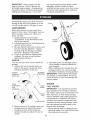
Owner's Manual
CRAFTSMAN°
ROTARY
160cc Honda Engine
Power-Propelled
21" Multi-Cut
Model No.
917.371813
• Espa_ol,
p. 21
CAUTION'.
Read and follow all
Safety Rules and Instructions
before operating this equipment
Sears, Roebuck and Co., Hoffman Estates, IL 60179 U.S.A.
Visit our Craftsman website: www.sears.com/craftsman
Warranty ...................................................
2
Safety Rules ..........................................
2-4
Product Specifications .............................. 4
Assembly / Pre-Operation ........................ 6
Operation .............................................
7-11
Maintenance Schedule ........................... 12
2-YEAR
FULL WARRANTY
Maintenance
......................................
12-15
Service and Adjustments
...................
16-18
Storage ..............................................
18-19
Troubleshooting
.................................
19-20
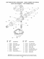
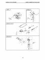
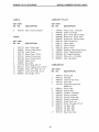
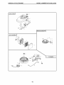
Repair Parts .......................................
40-51
Sears Service ..........................
Back Cover
ON CRAFTSMAN
LAWN MOWER
If this Craftsman Lawn Mower fails due to manufacturer defects in material or
workmanship within two years from the date of purchase, return it to any Sears store,
Parts & Repair Center or other Craftsman outlet for free repair (or replacement if repair
proves impossible),
This warranty applies for only 90 days from the date of purchase
ever used for commercial
or rental purposes.
This warranty
does
if this Lawn
Mower
is
not cover:
Expendable
items that become worn during normal use, such as rotary mower
blades, blade adapters,
belts, air cleaners and spark plug.
Repairs necessary
because of operator abuse or negligence,
crackshafts
and the failure to assemble,
operate or maintain
according
to all supplied product instructions.
This warranty
only while
this product
is used in the United
This warranty gives you specific
vary from state to state.
legal rights,
and you may also have other
Sears,
applies
including
this Lawn
Roebuck
and Co.,
Hoffman
Estates,
States.
rights which
IL 60179
IMPORTANT:
This cutting machine is capable of amputating
ing objects. Failure to observe the following safety instructions
injury or death.
_l, Look for this symbol to point out important safety precautions. It means
CAUTION!H
BECOME ALERT!H
YOUR SAFETY IS INVOLVED.
_, WARNING:
In order to prevent accidental starting when setting up, transporting, adjusting or making repairs,
always disconnect spark plug wire and
place wire where it cannot come in contact
with plug.
• i,WARNING: Engine exhaust, some of its
constituents, and certain vehicle components
contain or emit chemicals known to the State
of California to cause cancer and birth defects
or other reproductive harm.
bent
Mower
hands and feet and throwcould result in serious
_I,WARNING:
Battery posts, terminals
and
related accessories
contain lead and lead
compounds,
chemicals
known to the State
of California
to cause cancer and birth
defects or other reproductive
harm. Wash
hands after handling.
A CAUTION:
Muffler and other engine
parts become extremely
hot during
operation
and remain hot after engine has
stopped. To avoid severe burns on contact,
stay away from these areas.
IoGENERAL OPERATION
• Read, understand,and follow all
instructions on the machine and in the
manual(s) before starting. Be thoroughly
familiar with the controls and the proper
use of the machinebefore starting.
• Do not put hands or feet near or under
rotatingparts. Keep clear of the discharge opening at all times.
• Onlyallow responsibleindividuals,familiar
withtheinstructions,tooperatethemachine.
• Clear the area of objects such as rocks,
toys, wire, bones, sticks, etc., which
could be picked up and thrown by blade.
Be sure the area is clear of other people
before mowing. Stop machine if anyone
enters the area.
• Do not operate the mower when barefoot or wearing open sandals. Always
wear substantial
foot wear.
• Do not pull mower backwards
unless absolutely necessary. Always look down and
behind before and while moving backwards.
• Never direct discharged
material toward
anyone. Avoid discharging
material against
a wall or obstruction.
Material may richochet back toward the operator.
Stop the
blade when crossing gravel surfaces.
• Do not operate the mower without
proper guards, plates, grass catcher or
other safety protective
devices in place.
• See manufacturer's
instructions
for
•
•
•
•
•
•
•
•
•
proper operation
and installation
of
accessories.
Only use accessories
approved by the manufacturer.
Stop the blade(s) when crossing gravel
drives, walks, or roads.
Stop the engine (motor) whenever
you
leave the equipment,
before cleaning the
mower or unclogging
the chute.
Shut the engine (motor) off and wait until
the blade comes to complete
stop before
removing
grass catcher.
Mow only in daylight / good artificial light.
Do not operate the machine while under
the influence of alcohol or drugs.
Never operate machine in wet grass.
Always be sure of your footing: keep a
firm hold on the handle; walk, never run.
Disengage
the self-propelled
mechanism or drive clutch on mowers so
equipped
before starting the engine.
If the equipment
should start to vibrate
abnormally,
stop the engine (motor) and
check immediately
for the cause. Vibration is generally
a warning of trouble.
AIwayswear
safety goggles or safety glasses with side shields when operating mower.
Ii. SLOPE
OPERATION
Slopes are a major factor related to slip &
fall accidents
which can result in severe
injury. All slopes require extra caution. If
you feel uneasy on a slope, do not mow it.
DO:
• Mow across the face of slopes: never
up and down. Exercise extreme caution
when changing direction on slopes.
Remove obstacles
such as rocks, tree
limbs, etc.
• Watch for holes, ruts, or bumps. Tall
grass can hide obstacles.
DO NOT:
• Do not trim near drop-offs,
ditches or
embankments.
The operator could lose
footing or balance.
• Do not trim excessively
steep slopes.
• Do not mow on wet grass. Reduced footing could cause slipping.
i11. CHILDREN
Tragic accidents
can occur if the operator
is not alert to the presence of children.
Children are often attracted to the machine
and the mowing activity. Never assume
that children will remain where you last
saw them.
• Keep children out of the trimming
area
and under the watchful
care of another
responsible
adult.
• Be alert and turn machine
enter the area.
off if children
• Before and while walking backwards,
look behind and down for small children.
• Never allow children to operate mower.
• Use extra care when approaching
blind
corners, shrubs, trees, or other objects
that may obscure vision.
IV. SAFE
HANDLING
OF
GASOLINE
Use extreme care in handling gasoline.
Gasoline is extremely
flammable
and the
vapors are explosive.
• Extinguish
all cigarettes,
cigars, pipes
and other sources of ignition.
• Use only an approved container.
• Never remove gas cap or add fuel with
the engine running.
Allow engine to cool
before refueling.
• Never refuel the machine indoors.
• Never store the machine or fuel container where there is an open flame, spark
or pilot light such as a water heater or on
other appliances.
• Never fill containers
inside a vehicle, on
a truck or trailer bed with a plastic liner.
Always place containers
on the ground
away from your vehicle before filling.
• Remove gas-powered equipmentfrom
the truck or trailer and refuel it on the
ground. If this is not possible, then
refuel such equipmentwith a portable
container, rather than from a gasoline
dispenser nozzle.
• Keep the nozzle in contact with the rim
of the fuel tank or container opening at
all times until fueling is complete. Do
not use a nozzle lock-opendevice.
• If fuel is spilledon clothing, change
clothing immediately.
• Never overfill fuel tank. Replacegas
cap and tighten securely.
V. GENERAL SERVICE
• Never run machine inside a closed area.
• Never make adjustments or repairs with
the engine(motor)running.Disconnectthe
spark plug wire, and keep the wire away
from plug to prevent accidentalstarting.
• Keep nuts and bolts, especially blade
attachment bolts, tight and keep equipment in good condition.
• Never tamperwith safetydevices. Check
their proper operation regularly.
• Keep machine free of grass, leaves, or
otherdebrisbuild-up.Cleanoil orfuel spillage.Allow machineto coolbeforestoring.
• Stop and inspectthe equipment if you
strike an object. Repair, if necessary,
before restarting.
• Never attempt to make wheel height
adjustmentswhile the engine is running.
• Grass catcher componentsare subject
to wear, damage, and deterioration,
which could expose moving parts or
allow objects to be thrown. Frequently
check componentsand replace with
manufacturer'srecommended parts,
when necessary.
• Mower blades are sharp and can cut.
Wrap the blade(s) or wear gloves, and
use extra caution when servicing them.
• Do not changethe engine governor setting or overspeed the engine.
• Maintain or replace safety and instruction labels, as necessary.
AWARNING: This lawn mower is equippedwith an internal combustionengine and
should not be used on or near any unimprovedforest-covered,brush-coveredor
grass-coveredland unless the engine's exhaustsystem is equippedwith a spark
arrester meeting applicable local or state laws (if any). If a spark arrester is used, it
should be maintained in effective working order by the operator.
In the state of California the above is required by law (Section4442 of the California
Public Resources Code). Other states may have similar laws. Federal laws apply on
federal lands. A spark arrester for the muffler is available through your nearest Sears
Parts & Repair Center (See the REPAIR PARTSsection of this manual).
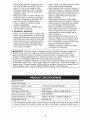
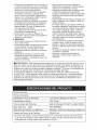
Serial Number:
Date of Purchase:
Gasoline Capacity / Type:
1.0 Quarts
Oil Capacity:
18.5 Ounces
Oil Type (API SG-SL):
SAE 30 (above
Spark
Plug (Gap:
NGK BPR6ES
Valve
Clearance
Blade
Bolt Torque:
• The model
housing,
,030")
(_+0.04 mm):
and serial
Record
numbers
both serial
Intake:
0,015
35-40
ft. Ibs.
will be found
number
(Unleaded
32°F) or SAE 10W-30
mm;
on a decal
Exhaust:
0,020
mm
on the rear of the lawn mower
and date of purchase
4
Regular)
in space
provided
above,
Repair Protection
Congratulations
on making a smart purchase. Your new Craftsman@
product is
designed
and manufactured
for years of
dependable
operation.
But like all products, it may require repair from time to
time. That's when having a Repair Protection Agreement
can save you money and
aggravation.
Purchase
a Repair Protection
Agreement
now and protect yourself from unexpected
hassle and expense.
Here's what's included in the Agreement:
•
Expert service
by our 12,000 profesional repair specialists.
•
Unlimited
service
and no charge for
parts and labor on all covered repairs.
•
Product
replacement
if your covered
product can't be fixed.
•
Discount
of 10% from regular price of
service and service-related
parts not
covered by the agreement;
also, 10%
off regular price of preventive
maintenance check.
Agreements
•
Fast help by phonephone support from a Sears representative
on
products requiring in-home repair, plus
convenient
repair scheduling.
Once you purchase the Agreement,
a
simple phone call is all that it takes for you
to schedule
service. You can call anytime
day or night, or schedule
a service appointment online.
Sears has over 12,000 professional
repair
specialists,
who have access to over 4.5
million quality parts and accessories.
That's the kind of professionalism
you can
count on to help prolong the life of your
new purchase for years to come. Purchase
your Repair Protection Agreement
today!
Some limitations
and exclusions
apply.
For prices and additional
information
call 1=800=827=6655.
Sears
Installation
Service
For Sears professional
installation
of home
appliances,
garage door openers, water
heaters, and other major home items, in
the U.S.A. call 1-800=4=MY-HOME®.
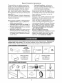
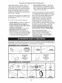
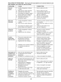
These accessories
were available when this lawn mower was produced.
They are not
shipped
with your mower. They are also available at most Sears retail outlets and
service centers.
Some of these accessories
may not apply to your lawn mower.
LAWN MOWER
PERFORMANCE
CLIPPING
DEFLECTORS
FOR
:1
STABILIZER
CANS
GAS
REAR DISCHARGE
LAWN MOWERS
GRASS
CATCHERS
FOR
GRASS
REAR DISCHARGE
LAWN MOWERS
LAWN MOWER
SIDE DISCHARGE
LAWN MOWERS
MAINTENANCE
MUFFLERS
BELTS
CATCHERS
FOR
AIR FILTERS
BLADES
BLADE ADAPTERS
SPARK PLUGS
WHEELS
ENGINE OIL
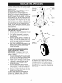
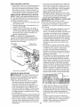
Read these
instructions
and this manual
in
its entirety before you attempt to assemble
or operate your new lawn mower.
IMPORTANT:
This lawn mower is shipped
WITHOUT
OIL OR GASOLINE
in the
engine.
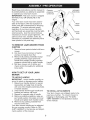
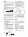
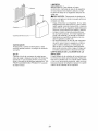
Your new lawn mower
Operator
presence
control bar
MOWING
POSITION
LIFT
UP
Upper
handle
has been assem-
bled at the factory with the exception
of
those parts left unassembled
for shipping
purposes.
To ensure safe and proper
operation
of your lawn mower, all parts
and hardware
you assemble
must be tightened securely.
Use the correct tools as
necessary
to ensure proper tightness.
All
parts such as nuts, washers,
bolts, etc.,
necessary
to complete the assembly
have
been placed in the parts bag.
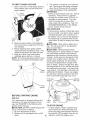
TO
REMOVE
LAWN
MOWER
Handle
knob
Lower handle
FROM
CARTON
1.
2.
3.
4.
Remove loose parts included with lawn
mower.
Cut down two end corners of carton
and lay end panel down flat.
Remove all packing materials except
padding between
upper and lower
handle and padding holding operator
presence
control bar to upper handle.
Roll lawn mower out of carton and
check carton
loose parts.
thoroughly
Knob
Bolt
/
Handle
bracket
for additional
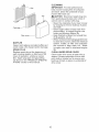
HOW TO SET UP YOUR LAWN
MOWER
TO UNFOLD
HANDLE
IMPORTANT:
Unfold handle carefully so
as not to pinch or damage control cables.
1. Raise lower handle section to operating position and align hole in handle
with one of the height positioning
holes
in handle bracket.
2.
Insert handle bolt through handle
bracket and secure with knob.
3.
4.
Repeat for opposite side of handle.
Remove protective
padding, raise upper handle section into place on lower
handle and tighten both handle knobs.
Remove any packing material from
around control bar.
5.
and
Your lawn mower handle can be adjusted
for your mowing comfort. Refer to "ADJUST HANDLE"
in the Service and Adjustments section of this manual.
TO INSTALL
ATTACHMENTS
Your lawn mower was shipped
used as a mulcher.
To convert
ready to be
mower to
bagging or discharging,
see "TO CONVERT MOWER"
in the Operation
section
of this manual.
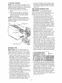
KNOW YOUR LAWN
READ
THIS
OWNER'S
MOWER
MANUAL
YOUR LAWN MOWER.
yourself with the location
future reference.
These symbols
product.
Learn
CAUTION
OR WARNING
AND ALL SAFETY
BEFORE
OPERATING
Compare
the illustrations
with your lawn mower to familiarize
of various controls and adjustments.
Save this manual for
may appear
on your lawn mower
and understand
their meaning.
ENGINE
ON
RULES
ENGINE
OFF
FAST
SLOW
CHOKE
or in literature
supplied
FUEL
OIL
with
the
DANGER, KEEP HANDS
AND FEET AWAY
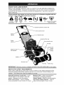
Operator presence control bar
- Drive control lever
Starter
handle
knob
Gasoline filler cap
Grass
catcher
Fuel shutoff valve
Air filter
,Dual point
height
adjuster
levers
Engine oil cal
with dipstick
Muffler
Mulcher door
Housing
IMPORTANT:
This lawn mower
is shipped
WITHOUT
Spark plug
OIL OR GASOLINE
in the engine.
MEETS CPSC SAFETY
REQUIREMENTS
Sears rotary walk-behind
power lawn mowers conform to the safety standards
American
National Standards
Institute and the U.S. Consumer
Product Safety
mission.
The blade turns when the engine is running.
Operator
presence
control
bar - must
be held down to the handle to start the
engine.
Release to stop the engine.
Drive control
leverused to engage
power-propelled
forward motion of mower.
Mulcher
door-
allows
conversion
of the
Com-
to
discharging
or bagging operation.
Starter
handle - used for starting engine.
Dual point height adjuster
- used to
adjust cutting height of lawn mower.
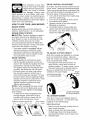
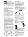
The operation of any lawn
mower can result in foreign
objectsthrowninto the eyes,
which can result in severe
eye damage, Always wear
safety glasses or eye shields while operating your lawn mower or performing any
adjustments or repairs, We recommend a
standardsafetyglassesor wide visionsafety
mask worn over spectacles,
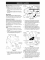
DRIVE
drive control housing to increase tension
the drive cable,
Proceed as follows:
1,
2,
HOW TO USE YOUR LAWN MOWER
ENGINE
4,
Engine speed was set at the factory for
optimum
performance,
It is not adjustable,
ENGINE ZONE CONTROL
ADJUSTMENT
Over time, the drive control system may become "loose", resulting in decreased
speed,
There is a turnbuckle on the underside of the
3,
SPEED
CONTROL
on
Turn unit off and disconnect
spark plug
wire from spark plug,
Turn nut on underside
of drive control
to increase drive speed,
Operate mower to test drive speed,
Readjust as required,
If condition
fails to improve after the
above steps (forward speed remains
the same), your drive belt is worn and
should be replaced,
_I, CAUTION:
Federal regulations
require
an engine control to be installed on this
lawn mower in order to minimize the risk
of blade contact injury, Do not under
any circumstances
attempt to defeat the
function of the operator control, The blade
turns when the engine is running,
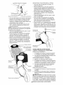
• Your lawn mower is equipped
with an
operator presence
control bar which
requires the operator to be positioned
behind the lawn mower handle to start
and operate the lawn mower,
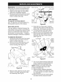
DRIVE CONTROL
• Self-propelling
is controlled
by holding the operator presence
control bar
down to the handle and pulling the drive
control lever rearward to the handle.
The farther toward the handle the lever
is pulled, the faster the unit will travel.
• Forward motion will stop when either
the operator presence
control bar or
drive control lever are released.
To stop
forward motion without stopping engine,
release only the drive control lever. Hold
operator presence
control bar down
against handle to continue mowing
without self-propelling,
NOTE: If after releasing the drive control
the mower will not roll backwards,
push
the mower forward slightly to disengage
drive wheels,
• To keep drive control engaged when
turning corners, push down on the
handle to lift the front wheels off the
ground
while
turning
lawn mower,
Operator presence control bar
TO
ENGAGE
DRIVE
CONTROL
Drive control
lever
DRIVE
CONTROL
DISENGAGED
Adjustment
turnbuckle
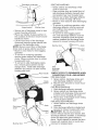
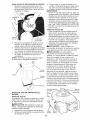
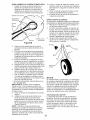
TO ADJUST
Both
lever
both
lever
CUTTING
HEIGHT
front wheels are adjusted by a single
on the left front wheel,
Likewise,
rear wheels are adjusted
by a single
on the left rear wheel,
• Pull adjuster lever toward wheel, To
raise mower, move lever forward to
desired position, To lower mower, move
the lever backward to desired position,
Be sure to adjust both front and rear
Height
wheels to the same height,
uster
lever
TO
LOWER
MOWER
LEVER
BACKWARD
LEVER FORWARD
TO RAISE MOWER
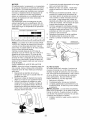
TO CONVERT
MOWER
Your lawn mower was shipped ready to
be used as a mulcher,
To convert to rear
bagging
REAR
or side discharging:
BAGGING
• Remove knob securing mulcher door to
lawn mower housing.
• Open mulcher door and insert tabs
of discharge
chute into hinge bracket
opening and position rear of chute over
threaded stud.
SIDE
DISCHARGING
• Grass catcher and discharge
must be removed.
Hinge bracket
Mulcher door
• Secure rear of discharge
chute to lawn
mower housing with knob.
• Place rear handle of grass catcher on
the crossbar of the lawn mower's lower
handle as shown.
• Lift the round door of the discharge
chute and place the grass catcher into
place on the discharge
chute.
NOTE: Be sure round door of discharge
chute rests on grass catcher as shown.
• Mower is now ready for rear bagging
operation.
• To convert to mulching
operation,
remove grass catcher and discharge
chute. Secure mulcher door to mower
• Open mulcher door and install front of
side discharge
deflector beneath door
and position rear over threaded stud.
• Secure rear of side discharge
deflector
to lawn mower housing with knob.
• Mower is now ready for side discharging
operation.
• To convert to mulching
operation,
side
discharge
deflector must be removed
and mulcher door secured to mower
housing with knob.
• To convert to rear bagging operation, side discharge
deflector must be
removed; discharge
chute and grass
catcher installed and discharge
chute
secured to mower housing with knob.
Mulcher door
-Crossbar
Knob
Threaded
stud
housing with knob.
• To convert to side discharging
operation, remove grass catcher and discharge chute.
Install side discharge
deflector and secure it to lawn mower
housing with knob.
handle
chute
Side
discharge
deflector
SIMPLE
STEPS
CONVERTING
FOR MULCHING
1.
Grass
2.
TO REMEMBER
WHEN
YOUR LAWN MOWER
-
Grass catcher, discharge
chute and
side discharge
deflector removed.
Mulcher door secured to mower hous-
ing with knob.
FOR REAR BAGGING
-
1.
2.
Side discharge
deflector removed.
Grass catcher and discharge
chute
installed with discharge
chute secured
to lawn mower housing with knob.
3. Round door of discharge
chute resting
on top of grass catcher.
FOR SIDE DISCHARGING
-
Round
door
1.
Dischar(
chute
2.
Threaded
stud
Mulcher door
Grass catcher
removed.
and discharge
chute
Side discharge
deflector installed and
secured to mower housing with knob.
_CAUTION:
Do not run your lawn
mower without mulcher door closed; side
discharge
deflector installed, or discharge
chute and approved grass catcher in
place, Never attempt to operate the lawn
mower with mulcher door or round door
removed or propped open,
TO EMPTY GRASS
1.
Open
move
grass
\
X
CATCHER
3.
round door of discharge
chute to
starter rope out and away from
catcher.
Front
handle..
You recieve
a container
unit. Slowly pour the
down the oil fill spout
4. Insert and tighten oil
IMPORTANT:
• Check oil level before
of oil with the
entire container
into the engine.
fill cap/dipstick.
each
use.
Add oil
if needed.
Fill to full line on dipstick.
• Change the oil after every 25 hours of
operation or each season.
You may
need to change the oil more often
under dusty, dirty conditions.
See "TO
CHANGE
ENGINE OIL" in the Maintenance section of this manual.
OPEN
ADD
GASOLINE
• Fill fuel tank to bottom
of tank filler
neck.
3.
Do not overfill.
Use fresh, clean, regular
unleaded
gasoline with a minimum
of
87 octane.
Do not mix oil with gasoline.
Purchase
fuel in quantities
that can be
used within 30 days to assure fuel freshness.
,_ CAUTION:
Wipe off any spilled oil or
fuel. Do not store, spill or use gasoline
near an open flame.
CAUTION:
Alcohol blended fuels
Stral:
(called gasohol or using ethanol or methanol) can attract moisture which leads to
separation
and formation
of acids during
storage.
Acidic gas can damage the fuel
system of an engine while in storage.
To
avoid engine problems, the fuel system
should be emptied before storage of 30
days or longer.
Empty the gas tank, start
the engine and let it run until the fuel lines
and carburetor
are empty.
Use fresh fuel
next season.
See Storage Instructions
for
additional
information.
Never use engine
or carburetor
cleaner products in the fuel
tank or permanent
damage may occur.
Round
door
2.
Starter
rope
Remove grass catcher with clippings
from lawn mower using both front and
rear handles.
Empty clippings from grass catcher
using both rear handle and strap. The
weight of the grass will open the door.
4. Snap door shut over frame before
installing grass catcher on mower.
NOTE: Do not drag the grass catcher when
emptying;
it will cause unnecessary
wear.
/
Rear
handle
/\
Oil fill cap /
dips
Gasoline
filler cap
\
, Front
handle
BEFORE
STARTING
ENGINE
ADD OIL
Your lawnmower is shipped without oil in
Upper
Lowe
mark
mark
the engine. For type and grade of oil to
use, see "ENGINE" in the Maintenance
TO STOP ENGINE
section of this manual.
A CAUTION: DO NOT overfill engine with
• To stop engine, release operator presence control bar. Wait until blade and
oil, or it will smoke on startup.
1. Be sure lawnmower is level.
all moving parts have stopped and turn
2. Remove oil fill cap/dipstick from oil fill
fuel valve to OFF position if you do not
spout.
10 intend to restart the engine soon.
TO START ENGINE
NOTE: Due to protectivecoatings on the
engine, a small amount of smoke may be
presentduring the initial use of the product
and should be considered normal,
1, Be sure fuel valve is in the ON position,
2, Hold operator presence control bar
down to the handle and pull starter
handle quickly, Do not allow starter
rope to snap back,
NOTE: The choke lever automatically
begins moving to the OFF positionwhen
operator presencecontrol bar is held
down to handle,
Keep top of engine around starter clear
and clean of grass clippings and chaff,
This will help engine air flow and extend
engine life,
MULCHING
• The special mulching blade will recut
the grass clippings
many times and
reduce them in size so that as they fall
onto the lawn they will disperse
into
the grass and not be noticed,
Also, the
mulched grass will biodegrade
quickly
to provide nutrients for the lawn, Always
mulch with your highest engine (blade)
speed as this will provide the best recutting action of the blades,
• Avoid cutting your lawn when it is wet,
Wet grass tends to form clumps and
interferes with the mulching
action, The
best time to mow your lawn is the early
afternoon,
At this time the grass has
dried, yet the newly cut area will not be
exposed to direct sunlight,
• For best results, adjust the lawn mower
cutting height so that the lawn mower
cuts off only the top one-third
of the
grass blades,
If the lawn is overgrown
it
will be necessary
to raise the height of cut
to reduce pushing effort and to keep from
overloading the engine and leaving clumps
of mulched
grass, For extremely
heavy
grass, reduce your width of cut by overlapping previously
cut path and mow slowly,
Fuel valve lever
MOWING
TIPS
Do not use de-thatcher
blade attachments
on your mower, Such
attachments
are hazardous,
will damage
your mower and could void your warranty,
MAX 1/3
• Under certain conditions,
such as very
tall grass, it may be necessary
to raise
the height of cut to reduce pushing
effort and to keep from overloading
the
engine and leaving clumps of grass clippings, It may also be necessary
to reduce ground speed and/or run the lawn
mower over the area a second time,
• For extremely
heavy cutting, reduce the
width of cut by overlapping
previously
cut path and mow slowly,
• For better grass bagging and most cutting conditions,
the engine speed should
be set in the FAST position,
• Pores in cloth grass catchers can become filled with dirt and dust with use
and catchers will collect less grass,
prevent this, regularly hose catcher
with water and let dry before using,
TIPS
IMPORTANT:
For best performance,
keep mower housing free of built-up
grass and trash, See "CLEANING"
in the
Maintenance
section of this manual,
OFF
A CAUTION:
MOWING
• Certain types of grass and grass conditions
may require that an area be mulched a second time to completely
hide the clippings,
When doing a second cut, mow across
(perpendicular)
to the first cut path,
• Change your cutting pattern from week
to week,
Mow north to south one week
then change to east to west the next
week, This will help prevent matting and
graining of the lawn,
To
off
11
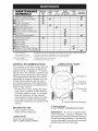
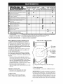
MAINTENANCE
SCHEDULE
Check
for Loose
BEFORE
EACH
USE
AFTER
EACH
USE
EVERY
10
HOURS
EVERY
25 HOURS
OR SEASON
EVERY
100
HOURS
BEFORE
STORAGE
Fasteners
_
Clean / Inspect
Check Tires
Grass
Catcher
_
Check
Drive Wheels
Clean
Lawn
Mower
M
Clean
under
Drive Cover
O
Check
Drive Belt / Pulleys
_
Check
/ Sharpen
*
v'
....
v'
***
***
/ Replace
Blade
R Lubrication
Clean
and Recharge
Check
Engine
Change
N
Clean Air Filter
_
Inspect
N
Replace
Empty
**
Oil level
_'
IE Replace
Battery
Engine
Oil
v'
Muffler
Spark
fuel system
mowers
*** Power-Propelled
mowers
**** Use a scraper
to clean under deck
GENERAL
Cartridge
v'
or add Stabilizer
* (if so equipped)
** Electric-Start
v'
Plug
Air Filter Paper
1 - Change more often if operating under a heavy load or in high outdoor
2 - Service more often if operating in dirty or dusty conditions.
3 - Replace blades more often when mowing in sandy soil,
temperatures.
4- Charge 48 hours at end of season.
5 - And after each 5 hours of use.
LUBRICATION
RECOMMENDATIONS
CHART
The warranty on this lawn mower does not
cover items that have been subjected
to
operator abuse or negligence.
To receive
full value from the warranty, operator must
maintain unit as instructed
in this manual.
Some adjustments
will need to be made
periodically
to properly maintain your unit.
At least once a season, check to see if
you should make any of the adjustments
described
in the Service and Adjustments
section of this manual.
I /
I
• Check
• Check
EACH
¢ Mulcher
\
')
_'
• At least once a year, replace the spark
plug, clean or replace air filter element
and check blade for wear. A new spark
plug and clean/new
air filter element
assure proper air-fuel mixture and help
your engine run better and last longer.
• Follow the maintenance
schedule
in this
manual.
BEFORE
Engine oil
I
door hinge pin
")
(_ Rear door
hinge
(_
_
USE
engine oil level.
for loose fasteners.
Handle bracket mounting pins
Spray
lubricant in Maintenance
See "ENGINE"
section.
IMPORTANT:
Do not oil or grease plastic
wheel
bearings.
Viscous
lubricants
will
attract dust and dirt that will shorten the life of
the self-lubricating
bearings.
If you feel they
must be lubricated, use only a dry, powdered
graphite type lubricant sparingly.
LUBRICATION
Keep unit well lubricated
(See "LUBRICATION
CHART").
12
LAWN
Always
forming
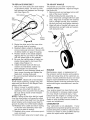
TIRES
MOWER
Trailing
observe safety rules when
any maintenance.
per-
Blade ada
• Keep tires free of gasoline,
oil, or insect
control chemicals which can harm rubber.
• Avoid stumps, stones, deep ruts, sharp
objects and other hazards that may
cause tire damage.
DRIVE WHEELS
Lockwasher
Check rear drive wheels each time you
mow to be sure they move freely. The
wheels not turning freely means trash,
grass cuttings, etc., may be inside the
drive wheel and dust cover area and must
be cleaned out to free drive wheels.
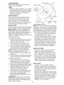
BLADE
Blade
For best results, mower blade must be kept
sharp.
Replace a bent or damaged
blade.
_, CAUTION:
Use only a replacement
blade approved
by the manufacturer
of
your mower.
Using a blade not approved
by the manufacturer
of your mower is
hazardous,
could damage your mower and
void your warranty.
1.
BLADE
2.
Disconnect
spark plug wire from spark
plug and place wire where it cannot
come in contact with plug.
Turn lawn mower on its side. Make
3.
sure air filter and carburetor
Use a wood block between
the straight nail exposed.
Place center
hole of blade over the head of the nail.
If blade is balanced,
it should remain in
a horizontal
position. If either end of the
blade moves downward,
sharpen the
heavy end until the blade is balanced.
are up.
blade and
mower housing to prevent blade from
turning when removing
blade bolt.
NOTE:
Protect your hands with gloves
and/or wrap blade with heavy cloth.
4. Remove blade bolt by turning counterclockwise.
5.
Remove blade and attaching
(bolt, lock washer, hardened
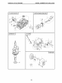
TO REPLACE
1.
2.
3.
4.
GRASS
BLADE
Position blade on the blade adapter
aligning the two (2) holes in the blade
with the raised lugs on the adapter.
Be sure the trailing edge of blade (opposite sharp edge) is up toward the engine.
Install the blade bolt with the lock
washer and hardened
washer into
mower
GEAR
model
number
when
ordering.
CASE
• To keep your drive system working
properly, the gear case and area around
the drive should be kept clean and free
of trash build-up.
Clean under the drive
cover twice a season.
and
• The gear case is filled with lubricant to the
proper level at the factory. The only time
the lubricant needs attention is if service
lawn mower housing and tighten the
blade bolt, turning clockwise.
• The recommended
tightening
torque is
35-40 ft. Ibs.
IMPORTANT:
Blade bolt is heat treated.
If bolt needs replacing,
replace only with
approved bolt shown in the Repair Parts
section of this manual.
CATCHER
• The grass catcher may be hosed with
water, but must be dry when used.
• Check your grass catcher often for damage or deterioration.
Through normal
use it will wear. If catcher needs replacing, replace only with approved
replacement catcher shown in the Repair Parts
section of this manual.
Give the lawn
hardware
washer).
blade adapter and crankshaft.
Use block of wood between blade
Blade
bolt
TO SHARPEN
BLADE
NOTE: We do not recommend
sharpening
the blade - but if you do, be sure the blade
is balanced.
Care should be taken to keep
the blade balanced. An unbalanced
blade will
cause eventual damage to mower or engine.
• The blade can be sharpened
with a file
or on a grinding wheel. Do not attempt
to sharpen while on the mower.
• To check blade balance, drive a nail into
a beam or wall. Leave about one inch of
CARE
TO REMOVE
Hardened
washer
•
13
has been performed
on the gear case.
If lubricant is required, use only Texaco
Starplex Premium
1 Grease, Part No.
750369.
Do not substitute.
ENGINE
Maintenance,repair,or replacementof
the emission control devices and systems,
which are being done at the customersexpense, may be performed by any non-road
engine repair establishmentor individual.
Warranty repairs must be performed by an
authorizedengine manufacturer'sservice
outlet.
,
5.
6.
Use guage on oil fill cap/dipstick
for
checking level.
Insert dipstick into
the tube and rest the oil fill cap on the
tube. DO NOT thread the cap into the
tube when taking reading.
LUBRICATION
Use
with
only
API
high quality
detergent
service
classification
oil rated
SG-SL.
Wipe off any spilled oil from lawn
mower or side of engine.
Fill engine with oil. Slowly pour oil
down the oil fill spout into the engine.
Wait one minute to allow oil to settle.
Oil fill cap /
dipstick
Select the oil's SAE viscosity grade according to your expected operating temperature.
SAE
VISCOSITY
GRADES
Upper _
1'_ _]'
°F
-20
°c -_o
0
-2o
TEMPERATURE
30
-1;
RANGE
32
40
;
60
80
_
ANTICIPATED
BEFORE
_o
k
mark
100
1o
Lower./
mark
NEXT OIL CHANGE
NOTE:
Multi-viscosity
oils (5W30, 10W30
etc.) improve starting in cold weather, and
you should check your engine oil level frequently to avoid possible engine damage
from running low on oil.
Change the oil after every 25 hours of
operation
or at least once a year if the
lawn mower is not used for 25 hours in
one year.
Check the crankcase
7. Continue adding small amounts of
oil and rechecking the dipstick until it
reads full. DO NOT overfill, or engine
will smoke on startup.
8. Always be sure to retighten oil fill cap/
dipstick before starting engine.
9. Reconnect spark plug wire to spark
plug.
oil level before
AIR FILTER
starting the engine and after each five (5)
hours of continuous
use. Tighten oil plug
securely each time you check the oil level.
TO CHANGE
ENGINE
Your engine will not run properly and may
be damaged
by using a dirty air filter,
Replace the air filter every 100 hours of
operation
or every season, whichever
occurs first, Service air cleaner more often
OIL
NOTE:
Before tipping lawn mower to drain
oil, empty fuel tank by running engine until
fuel tank is empty.
1. Disconnect
spark plug wire from spark
plug and place wire where it cannot
come in contact with plug.
2. Remove oil fill cap/dipstick;
lay aside
on a clean surface.
3.
under
any oil trapped
inside
dusty
TO CLEAN
1.
2.
3.
Remove
conditions,
AIR FILTER
cover.
Carefully
remove cartridge.
Clean by gently tapping on a flat surface. If very dirty, replace cartridge.
_LCAUTION:
Petroleum
solvents, such
as kerosene, are not to be used to clean
cartridge. They may cause deterioration
of the cartridge.
Do not oil cartridge.
Do
not use pressurized
air to clean or dry
cartridge.
4. Install cartridge, then replace cover.
Tip lawn mower on its side as shown
and drain oil into a suitable container.
Rock lawn mower back and forth to remove
',
of engine.
14
CLEANING
iMPORTANT:
For best performance,
keep mower housing free of built-grass
and trash. Clean the underside of your
mower after each use.
Tab
_kCAUTION:
Disconnect
spark
plug wire
from spark plug and place wire where
cannot come in contact with plug.
• Clean the underside
of your lawn mower
by scraping to remove build-up of grass
and trash.
• Clean engine often to keep trash from
accumulating.
A clogged engine runs
hotter and shortens engine life.
• Keep finished surfaces
and wheels free
of all gasoline,
oil, etc.
• We do not recommend using a garden hose
to clean lawn mower unless the electrical
Cartridge
Filter covel
MUFFLER
system,
muffler, air filter and carburetor
are covered
to keep water out.
Water
in engine can result in shortened
engine
life.
Inspect and replace corroded muffler as it
could create a fire hazard and/or damage.
SPARK
it
PLUG
CLEAN
Replace spark plug at the beginning
of
each mowing season or after every 100
hours of operation,
whichever
occurs
first. Spark plug type and gap setting
are shown in the "PRODUCT
SPECIFICATIONS" section of this manual.
Clean
UNDER
under
DRIVE
drive cover
COVER
at least twice
a
season. Scrape underside of cover with
putty knife or similar tool to remove any
build-up of trash or grass on underside
of
drive cover.
15
_I:_WARNING:
To avoid serious injury, before
performing
any service and adjustments:
1.
2.
3.
Return spring
/
MOWER
TO ADJUST
CUTTING
the Operation
REAR
HEIGHT
CUTTING
section
pulley
HEIGHT"
in
The rear deflector, attached
rear wheels of your mower,
minimize the possibility
that
thrown out of the rear of the
Figure
between the
is provided to
objects will be
mower into
5.
6.
the operator mowing position.
If deflector
becomes damaged,
it should be replaced.
housing
BELT
(See Figure
Pivot
drive
drive
Turn
\
assembly
B
idler arm assembly
to slacken
belt, then remove drive belt from
pulley, belt keepers and idler arm.
lawn mower on its side. Make
sure air filter and carburetor
are up.
Remove screw securing debris shield.
Note that the debris shield has a tab
which fits into a gap in the housing
(See Figure C).
Disconnect
spark plug wire from spark
plug and place wire where it cannot
come in contact with plug.
Remove screws retaining drive cover
and remove drive cover from lawn
mower
PIVOT
of this manual.
4.
DRIVE
Idler arm
Belt keeper
DEFLECTOR
TO REMOVE
Housing
hole
Drive
See "TO ADJUST
2.
Drive belt
Release control bar and stop engine.
Make sure the blade and all moving
parts have completely
stopped.
Disconnect
spark plug wire from spark
plug and place wire where it cannot
come in contact with plug.
LAWN
1.
Drive cable anchor
Crankshaft
Tab
Blade
Housing
hole
\
adapter
(pulley
end)
A).
Hardened
washer
Blade
bolt
Screw
Lawn
mower
housing
Figure C
7.
Drive
cover
Use a wood
block
between
blade
and
mower housing to prevent blade from
turning when removing
blade bolt.
NOTE: Protect your hands with gloves
and/or wrap blade with heavy cloth.
8. Remove blade bolt.
Figure A
9.
,
Lock-washer
Trailing edge
Remove blade, attaching hardware
(bolt, lock washer and hardened
washer), blade adapter and debris shield as
one assembly.
10. Remove drive belt from blade adapter
and debris shield; discard old belt.
Remove drive cable from anchor, then
detach it and return spring from idler
arm assembly (See Fig, B),
16
TO REPLACE
1.
DRIVE
BELT
TO ADJUST
Place new drive belt in the belt retainer
of the debris shield.
Be sure to route
belt between belt keepers
slot (See Figure D).
The handle on your lawn mower has
multiple height positions - adjust to height
that suits you.
1. Remove knob and carriage bolt on left
side of the lower handle.
and through
Belt retainer
HANDLE
Tab
2.
Belt
kee
Drive
belt
3.
While holding handle assembly, remove knob and carriage bolt from right
side. Align hole in handle with desired
hole in handle bracket, then reassemble bolt and knob and tighten securely.
Align left side of handle with same positioning hole as right side and secure
with bolt and knob.
Knob
Bolt
\
Slot
Debris
shield
Figure D
2.
3.
4.
5.
6.
7.
Route
the other
Low
end of the new drive
Hi
belt through hole in housing.
Reattach debris shield to housing with
screw previously
removed.
Be sure tab
of debris shield is in gap of housing.
Position blade on the blade adapter
aligning the two (2) holes in the blade
with the raised lugs on the adapter.
Be sure the trailing edge of blade (opposite sharp edge) is up toward the
engine (See Figure C).
Install the blade bolt with the lock
washer and hardened
washer into
blade adapter and crankshaft.
Use block of wood between blade
Handle
ENGINE
and
lawn mower housing and tighten the
blade bolt, turning clockwise.
• The recommended
tightening
torque is
35-40 ft. Ibs.
IMPORTANT:
Blade bolt is heat treated.
Maintenance,
repair, or replacement
of
the emission control devices and systems,
which are being done at the customers
expense, may be performed
by any non-road
engine repair establishment
or individual.
Warranty
repairs must be performed
by an
authorized
engine manufacturer's
service
outlet.
If bolt needs replacing,
replace only with
approved bolt shown in the Repair Parts
section of this manual.
8.
9.
Return mower to upright position.
Install new drive belt into idler arm
ENGINE
Your engine speed has been factory set.
Do not attempt to increase engine speed
or it may result in personal injury. If you
believe that the engine is running too fast
or too slow, take your lawn mower to a
Sears or other qualified service center for
repair and adjustment.
assembly,
then around the drive pulley.
Be sure belt is inside of belt keepers
(See Figure B).
NOTE: Pulling on the drive belt (to install
it on the drive pulley) will cause the other
end of the belt to free itself from the debris
shield retainer and properly seat itself in
groove of pulley end of the blade adapter.
10. Reattach drive cable and return spring
to the idler arm assembly, then reattach drive cable to anchor.
11. Reattach drive cover with screws previously removed.
12. Connect
spark
plug wire to spark
plug.
SPEED
CARBURETOR
Your carburetor
is not adjustable.
If your
engine does not operate properly due to suspected carburetor
problems, take your lawn
mower to a Sears or other qualified service
center for repair and/or adjustment.
17
IMPORTANT:
Never tamper with the
engine governor,
which is factory set
for proper engine speed.
Overspeeding
the engine above the factory high speed
setting can be dangerous.
If you think
the engine-governed
high speed needs
adjusting,
contact a Sears or other
qualified service center, which has proper
equipment
and experience
to make any
necessary
adjustments.
Immediately
prepare your lawn mower for
storage at the end of the season or if the
unit will not be used for 30 days or more.
LAWN
When
\
\
MOWER
lawn
mower
is to be stored
for a
Handle
bracket
tion of this manual).
Lubricate
as shown in the Maintenance
section of this manual.
3.
4.
Bolt
\
period of time, clean it thoroughly,
remove
all dirt, grease, leaves, etc. Store in a
clean, dry area.
1. Clean entire lawn mower (See
"CLEANING"
in the Maintenance
sec2.
\
Knob
Be sure that all nuts, bolts, screws, and
pins are securely fastened.
Inspect
moving parts for damage,
breakage
and wear. Replace if necessary.
Touch up all rusted or chipped paint
surfaces.
Be sure to sand surface
lightly
HANDLE
before
painting.
You can fold your lawn mower handle for
storage.
1. Loosen the two (2) handle knobs on
sides of the upper handle and allow
handle to fold down to the rear.
Operator
presence
control bar
3.
Reinstall knobs and carriage bolts to
lower handle or handle brackets for
safe keeping.
• When setting up your handle from the
storage position, you must manually
lock lower handle into mowing position.
IMPORTANT:
When folding the handle
for storage or transportation,
be sure to
fold it as shown or you may damage the
control cables.
MOWING
POSITION
ENGINE
Upper
handle
FUEL
IMPORTANT:
It is important to prevent
gum deposits from forming in essential
fuel system parts such as carburetor,
fuel
filter, fuel hose, or tank during storage.
Alcohol blended fuels (called gasohol or
using ethanol or methanol)
can attract
moisture which leads to separation
and
formation
of acids during storage. Acidic
gas can damage the fuel system of an
engine while in storage.
Handle
knob
Lower handle
,
SYSTEM
Remove the two (2) handle knobs and
carriage bolts on sides of the lower
handle and pivot entire handle assembly forward and allow it to rest on
mower.
• Empty the fuel tank by starting the engine and letting it run until the fuel lines
and carburetor
are empty.
18
• Never use engine or carburetor
cleaner
products in the fuel tank or permanent
damage may occur.
• Use fresh fuel next season.
3. Pull starter handle slowly a few times
to distribute oil.
4, Replace with new spark plug,
NOTE:
Fuel stabilizer is an acceptable
alternative
in minimizing
the formation of
fuel gum deposits during storage.
Add
stabilizer to gasoline in fuel tank or storage container.
Always follow the mix ratio
found on stabilizer container.
Run engine
at least 10 minutes after adding stabilizer
to allow the stabilizer to reach the car-
OTHER
• Do not store gasoline
to another.
• Replace your gasoline can if your can
starts to rust. Rust and/or dirt in your
gasoline will cause problems.
If possible, store your unit indoors and
cover it to protect it from dust and dirt.
• Cover your unit with a suitable protective cover that does not retain moisture.
buretor.
Do not empty the gas tank and
carburetor
if using fuel stabilizer.
Do not use plastic.
Plastic cannot
breathe, which allows condensation
to
form and will cause your unit to rust.
IMPORTANT:
Never cover mower while
ENGINE OIL
Drain oil (with engine warm) and replace
with clean engine oil. (See "ENGINE" in
the Maintenance section of this manual).
engine and exhaust areas are still warm.
_I.CAUTION:
Never store the lawn mower
CYLINDER
1.
2.
with gasoline in the tank inside a building
where fumes may reach an open flame
or spark. Allow the engine to cool before
storing in any enclosure.
Remove spark plug.
Pour one ounce (29 ml) of oil through
spark plug hole into cylinder.
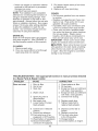
TROUBLESHOOTING
to a Sears Parts
PROBLEM
Does
not start
from one season
- See appropriate
section
& Repair Center.
CAUSE
in manual
unless
directed
CORRECTION
1.
2.
3.
Dirty air filter.
Out of fuel.
Stale fuel.
1.
2.
3.
4.
Water
4.
5.
Spark plug wire
disconnected.
6.
7.
Bad spark plug.
Loose blade or broken
in fuel.
is
5.
6.
7.
Replace spark plug.
Tighten blade bolt or
replace blade adapter.
8.
Depress
handle.
blade adapter.
8.
Control
9.
position.
Control bar defective.
bar in released
10. Fuel valve lever (if so
equipped)
in OFF position.
11. Weak battery (if equipped).
12. Disconnected
battery
connector
(if equipped).
19
Clean/replace
air filter.
Fill fuel tank.
Empty fuel tank and refill tank
with fresh, clean gasoline.
Empty fuel tank and refill tank
with fresh, clean gasoline.
Connect wire to plug.
control
bar to
9. Replace control bar.
10.Turn fuel valve lever
to the ON position.
11. Charge battery.
12. Connect battery to engine.
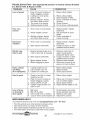
TROUBLESHOOTING
to a Sears
Parts
PROBLEM
- See appropriate
section
& Repair Center.
CAUSE
Loss of power
1.
2.
3.
4.
5.
6.
Poor cut =
uneven
Too much oil in engine.
Walking speed too fast.
1. Worn,
bent or loose
2.
heights
3.
Excessive
vibration
blade.
uneven.
Buildup of grass, leaves
and trash under mower.
1. Worn,
2.
bent or loose
Bent engine
1. Raise cutting height.
2.
3.
4.
5.
Raise cutting height.
Clean/replace
air filter.
Clean underside of mower
housing.
Check oil level.
6.
Cut at slower
1.
2.
Replace blade. Tighten
blade bolt.
Set all wheels at same
3.
height.
Clean underside
mower
blade.
1.
2.
crankshaft.
,
,
3.
4.
Engine flywheel brake is on
when control bar is released.
1.
Bent engine
2.
Blade
Blade
crankshaft.
adapter broken.
dragging in grass.
3.
4.
walking
speed.
of
housing.
Replace blade. Tighten
blade bolt.
Contact a Sears or other
qualified
Starter rope
hard to pull
unless directed
CORRECTION
Rear of mower housing or
blade dragging
in grass.
Cutting too much grass.
Dirty air filter.
Buildup of grass, leaves,
and trash under mower.
Wheel
in manual
service
center.
Depress control bar to
upper handle before
pulling the starter rope.
Contact a Sears or other
qualified service center.
Replace blade adapter.
Move lawn mower to cut
grass or to hard surface.
Grass
catcher
not filling
(if so equipped)
Hard
to push
1.
2.
Cutting height too low.
Lift on blade worn off.
3.
Catcher
1.
Grass is too high or wheel
height is too low.
Rear of mower housing or
blade dragging
in grass.
Grass catcher too full.
2.
3.
not venting
4.
Handle height
right for you.
Loss of drive
1.
Belt wear.
or slowing of
drive speed
2.
3.
Belt off of pulley.
Drive cable worn
4.
"Loose"
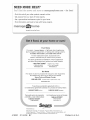
NEED
MORE
Find
Get
Get
Find
position
not
Raise cutting height.
Replace blade.
Clean grass catcher.
1.
Raise
control
system.
height.
2.
Raise rear of mower housing
one (1) setting higher.
3. Empty grass catcher.
4. Adjust handle height to suit.
1.
2.
or broken.
cutting
Check/replace
Check/reinstall
drive belt.
drive belt.
3. Replace drive cable.
4. Adjust drive control.
HELP?
You'll find the answer
•
•
•
•
drive
air.
1.
2.
3.
and more on managemyhome.com
= for free!
this and all your other product manuals online.
answers from our team of home experts.
a personalized
maintenance
plan for your home.
information
and tools to help with home projects.
brought to you by Sears
20
Garantia .........................................................
21
Reglas de Seguridad ................................ 21-23
Especificaciones del Producto ....................... 23
Montaje / Pre-Operaci6n ............................... 25
Operaci6n .................................................
26-30
Mantenimiento ..........................................
31-34
GARANTiA
TOTAL
DE LA CORTADORA
Programa de Mantenimiento ......................... 31
Servicio y Adjustes ...................................
35-37
Almacenamiento .......................................
37-38
ldentificaci6n de problemas ...................... 38-39
Partes de repuesto ..................................
40-51
Servicio Sears .................................. Contratapa
DE ClaSPED
CRAFTSMAN
POR 2 ANOS
Si esta Segadora Craftsman Ilega a presentar algQn desperfecto por defectos de materiales
o fabricaci6n durante un plazo de dos afios a partir de la fecha de compra, Ilevela de vuelta a
cualquiera de las tiendas Sears, al Centro de Repuestos y Reparaci6n, o a otro comercio donde se
vendan los equipos Craftsman, a efectos de que se la reparen sin costo (o bien se la reemplacen,
en caso que no sea posible repararla).
Siesta Segadora Ilega a ser utilizada con fines comerciales o arrendada,
vigencia por s61o 90 dias a partir de la fecha de compra.
la presente garantia tendra
La presente garantia no cubre:
• Aquellas piezas fungibles que se desgastan por el uso normal, tales como las cuchillas rotatorias
de la cortadora, los adaptadores de las cuchillas, las correas, los filtros de aire y las bujias.
• Aquellas reparaciones que haya que hacer debido a mal uso o negligencia por parte del operador,
incluidos el arbol del cigQefial torcido u omisiones relativas al armado, manejo o mantenimieno de
la Segadora en un todo de acuerdo alas instrucciones provistas con el equipo.
La presente garantia se aplicara solamente
en tanto el articulo sea usado en los Estados Unidos.
Esta garantia le otorga a usted derechos legales especificos;
derechos, los cuales varian de estado a estado.
puede que usted tenga, ademas, otros
Sears, Roebuck and Co., Hoffman Estates, IL 60179
IIVlPORTANTE: Esta maquina cortadaora es capaz de amputar las manos y los manos y los pies y
de lanzar objetos. Si no se observan las instrucciones de seguridad siguientes se pueden producir
lesiones graves o la muerte.
_i, Busque este simbolo que sefiala las precauciones de seguridad de importancia. Quiere
decir - iiiATENCION!H iiiESTE ALERTO!!!
U SEGURIDAD ESTA COMPROMETtDA.
ADVERTENClA:
Siempre desconecte el
alambre de la bujia y p6ngalo donde no pueda
entrar en contacto con la bujia, para evitar el
arranque por accidente, durante la preparaci6n,
el transporte, el ajuste o cuando se hacen
re paraciones.
• IIADVERTENClA:
Los bornes, terminales y
accesorios relativos de la bateria contienen
plomo o compuestos de plomo, productos
quimicos conocidos en el Estado de California
como causa de cancer y defectos al nacimiento
u otros dafios reproductivos. Lavar las manos
despu_s de manipularlos.
,_PRECAUClON:
El tubo de escape del motor,
algunos de sus constituyentes y algunos componentes del vehiculo contienen o desprenden
productos quimicos conocidos en el Estado de
California como causa de cancer y defectos al
,_cimiento u otros dafios reproductivos.
PRECAUClON:
El silenciador y otras piezas
del motor Ilegan a sre extremadamente calientes durante la operaci6n y siguen siendo calientes despues de que el motor haya parado.
Para evitar quemaduras severas, permanezca
lejos de estas areas.
21
I. OPERACION
, Antes de empezar, debe familiarizarse
completamente con los controles y el uso
correcto de la maquina. Para esto, debe leer
y comprender todas las instrucciones que
aparecen en la maquina yen los manuales
de operaci6n.
* No ponga las manos o los pies cerca o
debajo de las partes rotatorias. Mantengase
siempre lejos de la abertura de la descarga.
* Permita que solamente las personas responsables que esten familiarizadas con las
instrucciones operen la maquina.
* Despeje el area de objetos tales como piedras, juguetes, alambres, huesos, palos, etc.
que pueden ser recogidos y lanzados por las
cuchillas.
* AsegOrese que el area no se hallen personas, antes de segar. Pare la maquina si
alguien entra en el area.
* No opere la maquina sin zapatos o con sandalias abiertas. P6ngase siempre zapatos
s61idos.
* No tire de la segadora hacia atras a menos
que sea absolutamente necesario. Mire
siempre hacia abajo y hacia detras antes y
mientras que se mueve hacia atras.
* Nunca dirigir el material descargado hacia
las personas. Evitar descargar material
contra paredes o barreras. El material puede
retornar al operador. Para la cuchilla cuando
se pasa por superficies de grava.
* No opere la segadora sin los respectivos
resguardos, las placas, el recogedor de
cesped u otros aditamentos dise ados para
su protecci6n y seguridad.
* Refierase alas instrucciones del fabricante
para el funcionamiento e instalaci6n de
accesorios. Use Onicamente accesorios
aprobados por el fabricante.
* Detenga la cuchilla o las cuchillas cuando cruce
pot calzadas, caries o caminos de grava.
* Parar el motor cada vez que se abandona el
aparato, antes de limpiar la segadora o de
remover residuos del tubo.
* Apagar el motor y esperar hasta que las
cuchillas esten completamente paradas
antes de remover el receptor de hierba.
* Segar solamente con luz del dia o con una
buena luz artificial.
* No opere la maquina bajo la influencia del
alcohol o de las drogas.
* Nunca opere la maquina cuando la hierba
este mojada. AsegOrese siempre de tener
buena tracci6n en sus pies; mantenga el
mango firmemente y camine; nunca corra.
* Desconectar el mecanismo de propulsi6n
aut6noma o el embrague de transmisi6n en
las segadoras que Io tienen antes de poner
en marcha el motor.
* Si el equipo empezara a vibrar de una
manera anormal, pare el motor y revise de
inmediato para averiguar la causa. Generalmente la vibraci6n suele indicar que existe
alguna averia.
* Siempre use galas de seguridad o anteojos
con protecci6n lateral cuando opere la segadora.
II. OPERAClON
SOBRE LAS CUESTAS
Los accidentes ocurren con mas frecuencia en
las cuestas. Estos accidentes ocurren debido a
resbaladas o caidas, las cuales pueden resultar
en graves lesiones. Operar la recortadora en
cuestas requiere mayor concentraci6n. Si se
siente inseguro en una cuesta, no la recorte.
HACER:
* Puede recortar a traves de la superficie de
la cuesta, nunca hacia arriba y hacia abajo.
Proceda con extrema precauci6n cuando
cambie de direcci6n en las cuestas.
* Renueva todos los objetos extraSos, tales
como guijarros, ramas, etc.
* Debe prestar atenci6n a hoyos, baches o
protuberancias. Recuerde que la hierba alta
puede esconder obstaculos.
NO HACER:
* No recorte cerca de pendientes, zanjas o
terraplenes. El operador puede perder la
tracci6n en los pies o el equilibrio.
* No recorte cuestas demasiado inclinadas.
* No recorte en hierba mojada. La reducci6n
en la tracci6n de la pisada puede causar
resbalones.
ill. NI OS
Se pueden producir accidentes tragicos si el
operador no presta atenci6n a la presencia
de los ni5os. A menudo, los niSos se sienten
atraidos por la maquina y por la actividad de
la siega. Nunca suponga que los ni5os van a
permanecer en el mismo lugar donde los vio
por Oltima vez.
* Mantenga a los ni_os alejados del area de
la siega y bajo el cuidado estricto de otra
persona adulta responsable.
* Este alerta y apague la maquina si hay niSos
que entran al area.
* Antes y cuando este retrocediendo, mire
hacia atras y hacia abajo para verificar si hay
niSos pequeSos.
* Nunca permita que los niSos operen la maquina.
* Tenga un cuidado extra cuando se acerque
a esquinas donde no hay visibilidad, a los
arbustos, &rboles u otros objetos que pueden
interferir con su linea de visi6n.
IV. MANEJO
SEGURO
DE GASOLINA
Usar mucha atenci6n cuando se maneja gasolina. La gasolina es extremamente inflamable y
los vapores son explosivos.
* Apagar todos los cigarrillos, cigarros, pipas y
otras fuentes de ignici6n.
* Usar solo un contenedor apropiado.
* Nunca quitar el tap6n de la gasolina o a_adir
carburante con el motor en marcha. Esperar
que el motor se enfrie antes de repostar la
gasolina.
* Nunca repostar la maquina al interior de un
local.
* Nunca guardar la maquina o el contenedor
de gasolina donde hay una llama abierta,
chispa o luz piloto como una caldera u otros
22 dispositivos.
, Nunca Ilenar contenedores en un vehiculo, en
un cami6n o caravana con un forro de plastico.
Colocar siempre los contenedores en el suelo
lejos de su vehiculo antes de Ilenar.
, Quitar equipos que funcionan con gasolina
del cami6n o caravana y repostar en el
suelo. Si esto no es posible, repostar dicho
equipo con un contenedor portatil, mas bien
que con una tobera de gasolina.
, Mantener la tobera en contacto con el bordo
del dep6sito de carburante o de la apertura
del contenedor siempre hasta terminar el
abastecimiento. No usar un dispositivo de
cierre-apertura de la tobera.
, Si el carburante cae en la ropa que se Ileva,
cambiarsela inmediatamente.
, Nunca Ilenar en exceso el dep6sito de
carburante. Colocar el tap6n de la gasolina y
apretar de modo seguro.
V. SERVIClO
* Nunca haga funcionar una maquina dentro
de un area cerrada.
, Nunca haga ajustes o reparaciones mientras
el motor este en marcha. Desconecte el
cable de la bujia, y mantengalo a cierta
distancia de esta para prevenir un arranque
accidental.
, Mantenga las tuercas y los pemos, especialmente los pernos del accesorio de la
cuchilla, apretados y mantenga el equipo en
buenas condiciones.
,
,
,
,
,
,
,
,
Nunca manipule de forma indebida los
dispositivos de seguridad. Controle regularmente su funcionamiento correcto.
Mantenga la maquina libre de hierba, hojas
u otras acumulaciones de desperdicio.
Limpie los derrames de aceite o combustible.
Permita que la maquina se enfrie antes de
almacenarla.
Pare e inspeccione el equipo si le pega a un
objeto. Reparelo, si es necesario, antes de
hacerlo arrancar.
En ningOn caso hay que regular la altura de
las ruedas mientras el motor esta en marcha.
Los componentes del receptor de la hierba
van sujetos a desgaste, dafios y deterioro,
que pueden exporter las partes en movimiento o permitir que objetos sean disparados. Controlar frecuentemente y cuando sea
necesario sustituir con partes aconsejadas
por el fabricante.
Las cuchillas de la segadora estan afiladas
y pueden cortar. Cubrir las hojas o Ilevar
guantes, y utilizar precauciones especiales
cuando se efectOa mantenimiento sobre las
mismas.
No cambie el ajuste del regulador del motor
ni exceda su velocidad.
Mantener o sustituir las etiquetas de
seguridad e instrucciones, cuando sea
necesario.
_ADVERTENCIA:
Este segadora viene equipado con un motor de combusti6n interna y no se
debe usar sobre, o cerca, de un terreno no desarrollado cubierto de bosques, de arbustos o de
cesped, o menos que el sistema de escape del motor venga equipado con un amortiguador de
chispas que cumpla con las leyes locales o estatales (si existen). Si se usa un amortiguador de
chispas, el operador debe mantenerlo en condiciones de trabajo eficientes.
En el estado de California, la ley exige Io anterior (Secci6n 4442 del "California Public Resources Code"). Otros estados pueden contar con otras leyes parecidas. Las leyes federales
se aplican en la tierras federales. Su centro de Servicio mas cercano tiene disponible amortiguadores de chispas para el silenciador (Vea la secci6n de PARTES DE REPUESTO en el
manual Ingles del duefio).
NQmero
Fecha
de Serie:
de Compra:
Capacidad
y Tipo de Gasolina:
1.0 Cuartos
Capacidad
de Aceite:
18.50nzas
Tipo de Aceite
Bujia
(Abertura:
Tolerancia
Torsi6n
(API SG-SL):
SAE 30 (Debajo
.030")
de Valvula
NGK
(_+0.004
del Perno de la Cuchilla:
(Regular
mm)
sin Plomo)
0°C/32°F)
o SAE 10W30
BPR6ES
Admisi6n:
0.015
mm; Descarga:
0.020
mm
35-40 ft. Ibs.
* El nOmero del nodelo y el de serie se encuentran en la calcomania adjunta a la parte trasera
de la caja de la segadora. Debe registrar tanto el nOmero de serie come la fecha de compra y
mantengalos en un lugar seguro para refencia en el futuro.
23
Acuerdos
de Protecci6n
Congratulaciones por su buena compra. Su
nuevo producto Craftsman® esta diseSado
y fabricado para funcionar de modo fiable pot
muchos aSos. Pero como todos los productos,
puede necesitar alguna reparaci6n de tanto
en tanto. En este caso tener un Acuerdo de
Protecci6n para la Reparaci6n puede hacerles
ahorrar dinero y fastidios.
para la Reparaci6n
Ayuda rapida por telefono - soporte telef6nico por parte de un representento Sears
sobre productos que requieren un arreglo en
casa, y ademas una programaci6n sobre los
a reglos mas convenientes.
Cuando se ha comprado el Acuerdo, basta con
una Ilamada telef6nica para programar el servicio. Puede Ilamar cuando quiera, dia y noche o
fijar en linea una cita para obtener el servicio.
Sears tiene mas de 12.000 especialistas
profesionales en la reparaci6n, que tienen
acceso a mas de 4.5 millones de partes y
accesorios de calidad. Este es el tipo de
profesionalidad con que puede contar para
ayudar a alargar la vida del producto que acaba
de comprar, pot muchos a_os. iCompre hoy su
Acuerdo de Protecci6n para la Reparaci6n!
Se aplican algunas limitaciones
y exclusiones. Para conocer los precios y tener
mas informacion, Ilame al 1-800-827-6655.
Compre ahora un Acuerdo de Protecci6n para
la Reparaci6n y protegese de molestias y gastos inesperados.
Un Acuerdo incluye los puntos siguientes:
* Servicio experto de nuestros 12.000 especialistas profesionales en la reparaci6n.
, Servicio ilimitado sin cargo alguno para
las partes y la mano de obra sobre todas las
reparaciones garantizadas.
, Sustitucion
del producto si su producto
garantizado no puede ser arreglado.
* Descuento del 10% sobre el precio corriente del servicio y de las partes relativas al
servicio no cubiertas por el acuerdo; tambien
el 10% menos sobre el precio corriente de
un control de mantenimiento preventivo.
Servicio de Instalaci6n Sears
Para la instalaci6n profesional Sears de
aparatos de casa, puertas de garaje,
calentadores de agua y otros importantes
articulos para la casa, en U.S.A. Ilamar a
1-800-4-MY-HOME®.
Estos accesorios estaban disponibles cuando se produjo la segadora. No son facilitados junto al
cortacesped.
Tambien estan disponibles en la mayoria de las tiendas de Sears yen los centros de
servicio. AIgunos de estos accesorios tal vez no se apliquen a su segadora.
RENDIMIENTO
DE LA SEGADORA
DESVIADOR
DE RECORTES
E GASOLINA
RECOREDOR
PARA
SEGADORAS
CON DESCARGA
LATERAL
PARA
SEGADORAS
CON DESCARGA
RECOREDOR
TRASERA
MANTENIMIENTO
DE LA SEGADORA
SILENCIADORES
FILTROS
BUJ|AS
DE AIRE
ADAPTADORES
CORREAS
ENVASES
ESTABILIZADORES
PARA SEGADORAS
CON DESCARGA
TRASERA
CUCHILLAS
DE CUCHILLA
24
ACEITE
RUEDAS
DEL MOTOR
Lea estas instrucciones y este manual completamente antes de tratar de montar u operar su
segadora nueva.
IMPORTANTE: Este cortacesped viene SIN
ACEITE O GASOLINA en el motor.
Barra
que sxige la
presencia del
operador
, SEGAR
/
Su segadora nueva ha sido montada en la
fabrica con la excepci6n de aquellas partes que
se dejaron sin montar por razones de envio.
Todas las partes como las tuercas, las arandelas, los pemos, etc., que son necesarias para
completar el montaje han sido colocadas en la
bolsa de partes. Para asegurarse que su segadora funcione en forma segura y adecuada,
todas las partes y los articulos de ferreteria que
se monten tienen que ser apretados seguramente. Use las herramientas correctas, como
sea necesario, para asegurar que se aprieten
adecuadamente.
PARA REMOVER
LA SEGADORA
LA CAJA DE CARTON
POSICION
PARA
/
////
/
LEVANTAR
Mango
superior
Manilla
del
mango
Mango
DE
Inferior
\
1.
Remueva las partes sueltas que se incluyen
con la segadora.
2. Corte las dos esquinas de los extremos
de la caja de cart6n y tienda el panel del
extremo piano.
3. Remueva todo el material de empaque, excepto la cuba entre el mango superior y 61
inferior, y la cuba que sujeta la barra de los
control que exige la presencia del operador
junto con el mango superior.
4. Haga rodar la segadora hacia afuera de la
caja de cart6n y revisela cuidadosamente
para verificar si todavia quedan partes
sueltas adicionales.
Perno
Manilla
Soporte
de mango
COMO PREPARAR
SU SEGADORA
PARA DESDOBLAR EL MANGO
IMPORTANTE:
Despliegue el mango con
mucho cuidado para no pellizcar o da_ar los
cables de control.
1. Levante la secci6n del mango inferior hasta
la posici6n de operaci6n y alinee el agujero
en este con uno de los agujeros para determinar la altura en el puntal del mango.
2. lnserte el perno del mango a traves de este
y del puntal y asegOrelo con la manilla.
3. Repita el procedimiento para el lado
opuesto del mango.
4. Levante la secci6n del mango superior
hasta la posici6n de operaci6n, remueva la
cuba protectora y apriete las manillas del
mango en forma segura.
5. Remueva el material de empaque de airededor de la barra de control.
El mango de la segadora puede ajustarse
segOn le acomode para segar. Refierase a
"AJUSTE DEL MANGO" en la secci6n de
Servicio y Ajustes de este manual.
PARA INSTALAR LOS ACCESORIOS
Su segadora fue enviada lista para usarse
como una acolchadora de capa vegetal. Para
convertirla de modo que pueda ensacar o
descarga, refierase a "PAPA CONVERTtR LA
SEGADORA" en la secci6n de Operaci6n de
este manual.
25
FAMILIARICESE
CON SU SEGADORA
LEA ESTE MANUAL DEL DUENO Y LAS REGLAS DE SEGURIDAD ANTES DE OPARAR SU
SEGADORA.
Compare las ilustraciones con su segadora para familiarizarse con la ubicaci6n de
los diversos controles y ajustes. Guarde este manual para referencia en el futuro.
Estos s[mbolos pueden apareser
producto.
Aprenda y comprenda
ATTENCION
O
ADVERTENCIA
MOTOR
ENCENDIDO
MOTOR
APAGADO
sobre su segadora
sus significados.
R_,PIDO
LENTO
o en la literatura
ESTRANGU
LACION
COMBUSTIBLE
proporcionada
ACEITE
con el
PELIGRO, GUARDE LAS
MANOS Y LOS PIES LEJOS
Barra de control que exige la
presencia del operador
Palanca de control de la impulsi6n
Cord6n
arrancador
Manilla del mango
Tapa del deposito de la gasolina
Recogedor
de cesped
Valvula del combustible
Filtro de aire
Mangos del
Tapa del deposito de
aciete del motor con
varilla indicadora
,ajustador de
un duel
punto
Puerta de la acolchadora
Caja
IMPORTANTE:
CUMPLE CON
Las segadoras
los estandares
Product Safety
Este cortacesped
Bujia
viene SIN ACEtTE O GASOLINA en motor.
LOS REQUISITOS DE SEGURIDAD DE LA CPSC
a motor, que se conducen desde la parte de atras, rotatorias, Sears, cumplen con
de seguridad del American National Standards Institute y de la U.S. Consumer
Commission.
La cuchilla gira cuando el motor esta funcionando.
Barra de control que e×ige la presencia del
operador- tiene que sujetarse abajo, junto
con el mango, para hacer arrancar el motor.
Sueltela para parar el motor.
Palanca de control de la impulsion - se usa
para enganchar la segadora para movimiento
hacia adelante impulsada a motor.
Cordon arrancador - se usa para hacer arrancar el motor.
Puerta de la acolchadora
- permite la conversi6n para la operaci6n de descarga o ensacado.
Mango del ajustador de un duel punto- se usa
para ajustar la altura de corte de la segadora.
26
AJUSTE DEL MANDO
Ocasionalmente, el sistema de mando puede
"aflojarse", provocando una disminuci6n de la
velocidad. Hay un torniquete en la parte trasera
de la sede del mando para apretar la tensi6n
del cable. Proceder de la siguiente manera:
1. Apagar la unidad y desconectar el cable de
bujia de la bujia.
2. Vuelta el tuerca en la parte inferior del
mando de transmisi6n para aumentar la velocidad del mecanismo.
3. Opere la segadora para probar la velocidad
del mecanismo. Reajuste seg0n Io requerido.
4. Si las condiciones no mejoran despues de los
pasos descritos (la velocidad hacia adelante
queda la misma), la correa de transmisi6n esta
desgastada y tiene que ser sustituida.
La operaci6n de cualquier
segadora puede hacer que
salten objetos extra_os dentro de
sus ojos, Io que puede producir
da_os graves en estos. Siempre
use anteojos de seguridad o protecci6n para
los ojos mientras opere su segadora o cuando
haga ajustes o reparaciones. Recomendamos
galas o una mascara de seguridad de visi6n
amplia de seguridad usada sobre las gafas.
COMO
USAR
SU SEGADORA
VELOCIDAD DEL MOTOR
La velocidad del motor se estableci6 en la fabrica para un rendimiento 6ptimo. La velocidad
no se puede ajustar.
NTROL DE ZONA DEL MOTOR
PRECAUCION: Las regulaciones federales
exigen que se instale un control para el motor
en esta segadora para reducir a un minimo el
riesgo de lesionarse debido al contacto con la
cuchilla. Por ningQn motivo trate de eliminar
la funci6n del control del operador. La cuchilla
gira cuando el motor esta funcionando.
. Su segadora viene equipada con una barra
de controles que exigen la presencia del
operador, Io que requiere que el operador
este detras del mango de la segadora para
hacerla arrancar y operarla.
Torniquete
PARA AJUSTAR LA ALTURA DE CORTE
Las dos ruedas delanteras se ajustan a traves
de una Qnica palanca en la rueda delantera
izquierda. Asimismo, las dos ruedas traseras
se ajustan a traves de una Onica palanca en la
rueda trasera izquierda.
. Tire de la palanca de ajustes hacia la rueda.
Levante la segadora, mueva la palanca
hasta delante a la posici6n deseada. Para
bajar la segadora, mueva la palanca hacia la
retaguardia.
Asegurarse de que las dos ruedas delanteras y
traseras esten reguladas a la misma altura.
CONTROL DE LA IMPULSION
. La autopropulsi6n se controla manteniendo
la palanca de mando operador presente
abajo hacia el mango y tirando la palanca de
accionamiento atras hacia el mango. Cuanto
mas lejos se tira la palanca hacia el mango,
mas rapida ira la unidad.
. El movimiento hacia adelante se detiene
cuando sea la palanca de mando operador
presente o la palanca de accionamiento se
sueltan. Para detener el movimiento hacia
adelante sin apagar el motor, soltar s61o
la palanca de accionamiento. Mantener la
palanca de mando operador presente abajo
contra el mango para continuar a cortar sin
autopropulsi6n.
AVlSO: Si despues haber desenganchado de la
palanca de control, la segadora no roda hacia
atras, empuje la segadora un poco hacia adelante
para desenganchar las ruedas de la impulsi6n.
. Para mantener el mando conectado cuando
se da la vuelta a una esquina, empujar el
mango para levantar las ruedas delanteras
del terreno mientras se gira la cortadora.
Barra
de control
que
)resencia
ATRA,
S PARA
BAJAR
PALANCA
HACIA
EL CORTAC[_SPED
_.
del operador
Control de
la impulsion
CONTROL
DE LA
IMPULSION
DESENGANCHADO
Jl_
PALANCAHAClAADELANTE
PARA
V_mP'
LEVANTAR EL CORTAOESPED
PARA CONVERTIR LA SEGADORA
Su segadora fue enviada lista para usarse
como acolchadora de capa vegetal. Para convertirla a una operaci6n de ensacado posterior
o de descargar lateral:
SEGADORAS CON DESCARGA TRASERA
.
PARA
ENGANCHAR
EL
CONTROL
DE LA
IMPULSION
ajuste
.
27
Quitar el pomo que fija la puerta del acabador al bastidor del cortacesped.
Abrir la puerta del acabador e introducir
las lengQetas del tubo de descarga en la
apertura de la brida de la articulaci6n y
colocar la parte trasera del tubo sobre el
pasador roscado.
LengL_etas
SEGADORAS
del tubo de descarga
_
Puerta de la acolchadora
, Fijar la parte trasera del canal de descarga al
bastidor del cortacesped a traves del pomo.
, Colocar el mango trasero del dep6sito de
hierba en la alzaprima del mango inferior del
cortacesped como mostrado.
, Alzar la puerta redonda del canal de eyecci6n y colocar el dep6sito de hierba en el
canal de eyecci6n.
AVlSO: Asegurarse de que la puerta redonda
del canal de eyecci6n se apoye en el dep6sito
de hierba como mostrado.
, Ahora el cortacesped esta listo para la operaci6n de ensacado trasero.
, Para convertir en la operaci6n de acabado,
quitar el dep6sito de hierba y el canal de
eyecci6n. Fijar la puerta del acabador al
bastidor del cortacesped a traves del pomo.
, Para convertir en la operaci6n de descarga,
quitar el dep6sito de hierba y el canal de
eyecci6n. Instalar el deflector de descarga
lateral y fijarlo al bastidor del cortacesped a
traves del pomo.
LATERAL
Hay que quitar el dep6sito de hierba y el
canal de eyecci6n.
Abrir la puerta de la puerta del acabador e
instalar la parte delantera del deflector de
descarga lateral debajo la puerta y colocar el
parte trasero en la esparrago fileteado.
Fijar la parte trasera del deflector de descarga lateral al bastidor del cortacesped a
traves del pomo.
Ahora el cortacesped esta listo para la operaci6n de descarga.
Para convertir a la operaci6n de acabado,
hay que quitar el deflector de descarga lateral y fijar la puerta del acabador al bastidor
del cortacesped a traves del pomo.
Para convertir en la operaci6n de ensacado
trasero, hay que quitar el deflector de descarga lateral; instalar el canal de eyecci6n y el
dep6sito de hierba y fijar el canal de descarga
al bastidor del cortacesped a traves del pomo.
/"
Soport_earticulacion
CON DESCARGA
Puerta dela
acolchadora
Manilla
-Pasador
roscado
go posterior
Desviadorde
Barra transversal
del mango
la descarga
inferior
El recogedor
cesped
PASOS StMPLES DE RECORDAR
CUANDO CONVIERTA SU SEGADORA
PARA ACOLCHAMtENTO
1.
El dep6sito de hierba, el canal de eyecci6n
y el deflector de descarga lateral quitados.
2. La puerta del acabador fijada al bastidor del
cortacesped a traves del pomo.
PARA ENSACAMtENTO TRASERO 1.
2.
redonda
Canal
inclinado
de
Manilla
la descarga
Pasador
roscado
Puerta
de la acolchadora
Deflector de descarga lateral quitado.
El dep6sito de hierba y el canal de eyecci6n
instalados con el canal de eyecci6n fijado al
bastidor del cortacesped a traves del pomo.
3. La puerta redonda del canal de descarga
apoyada sobre la parte superior del
dep6sito de hierba.
PARA DESCARGA LATERAL1.
El dep6sito de hierba y el canal de eyecci6n
quitados.
2. El deflector de descarga lateral instalados y
fijados al bastidor del cortacesped a traves
del pomo.
• _, PRECAUClON:
No haga funcionar su segadora sin la puerta trasera se cerr6, desviador de
la descarga instalada, o sin el canal inclinado de
la descarga o el recogedor cesped aprobados
en su lugar. Nunca trate de operar la segadora
cuando se ha removido a puerta trasera o puerta
28redonda cuando esta un poco abierta.
PARAVACIAREL RECOGEDOR
DEC_:SPED
1. Abiertola puertaredondadelcanalinclinadode la descargaparamoverla cuerda
delarrancadorhaciafueray lejosdesdeel
recogedorde cesped.
"
Mango
X
anterior
ABtERTO
Puerta
redonda
Cuerda del
arrancador
2.
Remueva el recogedor de cesped, con los
recortes, de la segadora usando tanto el
mango anterior como 61 mango posterior.
3. Vacie los recortes de el recogedor de cesped
usando tanto el mango posterior como 61correa. El peso de la hierba abrira la puerta.
4. Cerrar fuerte la puerta en el armaz6n antes
de instalar de dep6sito de hierba en el
cortacesped.
AVlSO: No arrastre la bolsa cuando la vacie;
se producira un desgaste innecesario.
L.
posterior
\
Correa
/\
\
Mango
\
\\
_
anterior
\
"_"_-'
Usted recibe un envase de aceite con la
unidad. Vierta lentamente el envase entero
de aceite en el tubo de relleno del motor.
4. lnserte y apriete la varilla medidora de aceite.
IMPORTANTE:
* Revise el nivel del aceite antes de cada uso.
Agregue aceite si es necesario. Llene hasta la
linea de Ileno en la varilla medidora de nivel.
* Cambie el aceite despues de 25 horas de
operaci6n o una vez por temporada. Puede
necesitar cambiar el aceite mas a menudo
cuando las condiciones son polvorosas o sucias. Vea "PARA CAMBIAR EL ACEITE DEL
MOTOR" en la seccion de Mantenimiento de
este manual.
AGREGUE GASOLINA
* Llene el estanque de combustible hasta la
parte inferior del cuello de relleno del estanque de gasolina. No Io Ilene demasiado.
Use gasolina regular, sin plomo, nueva y limpia con el minimo de 87 octanos. No mezcle
el aceite con la gasolina. Para asegurar
que la gasolina utilizada sea fresca compre
estanques los cuales puedan ser utilizados
durante los primeros 30 dias.
_PRECAUCl6N:
Limpie el aceite o el
combustible derramado. No almacene, derrame
o use gasolina cerca de una llama expuesta.
,I_PRECAUCl6N:
Los combustibles
mezclados con alcohol (conocidos como
gasohol, o el uso de etanol o metanol) pueden
atraer la humedad, la que conduce a la
separaci6n y formaci6n de acidos durante el
almacenamiento. La gasolina acidica puede
da_ar el sistema del combustible de un motor
durante el almacenamiento. Para evitar los
problemas con el motor, se debe vaciar el
sistema del combustible antes de guardarlo
pot un periodo de 30 dias o mas. Vacie el
estanque del combustible, haga ar rancar el
motor y hagalo funcionar hasta que las lineas
del combustible y el carburador queden vacios.
La pr6xima temporada use combustible nuevo.
Vea las tnstrucciones Para El AImacenamiento
para mas informaci6n. Nunca use productos de
limpieza para el motor o para el carburador en
el estanque del combustible pues se pueden
producir da_os permanentes.
Mango
\
3.
Puerta
Tapa del deposito
de aceite
ANTES DE HACER
MOTOR
ARRANCAR
EL
con
varilla
de
nivel
AGREGUE ACEITE
Su segadora fue enviada sin aceite en el motor.
Para el tipo y el grado del aceite a utilizar, vea
el "MOTOR" en la secci6n del Mantenimiento
de este manual.
_I, PRECAUCl6N:
NO sobrellene el motor con
de gasolina
aceite, o fumara pesa demante del silenciador
cuando Io valla a arrancar.
1.
2.
AsegOrese que la segadora este nivelada.
Remueva la varila medidora de aceite del tubo
de desarga de aceite.
29
Tapa del
rellenador
Marca
Marca
superior
inferior
PARA
PARAR
EL MOTOR
.
._ Para parar el motor y si no intenta ponerlo en
marcha de nuevo, alivie la barra de control
que exige la presencia del operador. Espere
hasta que la cuchilla y todas las piezas m6viles se hallan parado y mueva la valvula del
combustible a la posicion APAGADO (OFF).
PARA
HACER
ARRANCAR
EL MOTOR
AVlSO: Debido alas capas protectoras del motor, una cantidad pequefia de humo puede estar presente durante el uso inicial del producto
y se debe considerar normal.
1. Asegurase que valvula del combustible este
en la posici6n ON.
2. Mueva la palanca de la estrangulaci6n a la
posici6n de ON
3. Sujete la barra de controles que exigen la
presencia del operador abajo en el mango
y tire el mango del arrancador rapidamente.
No permita que el cord6n arrancador se
devuelva abruptamente.
AVlSO: La palanca de la estrangulaci6n
comienza a moverse automaticamente
a la
posici6n de APAGADO (OFF) cuando la barra
del control de la presencia del operador se
mantiene hacia el mango.
<I",1)
APAGADO
__(OFF)
Palanca
Los poros en los recogedores de cesped de
tela pueden Ilenarse con mugre y polvo con
el uso y los recogedores recaudaran menos
cesped. Para evitar este, rocie el recogedor
con la manguera de agua, regularmente, y
dejelo secarse antes de usarlo.
. Mantenga la parte superior del motor, alrededor del arrancador, despejada y sin recortes
de cesped y paja. Esto ayudara el flujo del
aire del motor y extendera su duraci6n.
CONSEJOS
PARA SEGARYACOLCHAR
IMPORTANTE: Para obtener el mejor
rendimiento mantenga la caja de la segadora
sin acumulacion de cesped y basura. Vea
"LtMPIEZA" en la seccion de Mantenimento de
este manual.
.
de la
ulacion
.
.
Valvula
del combustible
La cuchilla acolchadora especial va a volver
a cortar los recortes de cesped muchas
veces, y los reduce en tamafio, de modo que
si se caen en el cesped se van a dispesar
entre este y no se van a notar. Tambien, el
cesped acolchado se va a deshacer rapidamente entregando substancias nutritivas para
el cesped. Siempre acolche con la velocidad
del motor (cuchilla) mas alta, pues asi se
obtendra la mejor acci6n de recorte de las
cuchillas.
Evite cortar el cesped cuando este mojado.
El cesped mojado tiende a formar montones
e interfiere con la acci6n de acolchado.
La mejor hora para segar el cesped es
temprano en la tarde. A esa hora este se ha
secado y el area recien cortada no quedara
expuesta al sol directo.
Para obtener los mejores resultados, ajuste
la altura del corte de la segadora de modo
que esta corte solamente el tercio superior
de las hojas de cesped. En el caso de que el
cesped haya crecido demasiado, puede ser
necesario el elevar la altura del corte para
reducir el esfuerzo necesario para empujar la
segadora y para evitar sobrecargar el motor,
dejando montones de recortes de cesped.
Para un cesped muy pesado, reduzca el ancho del corte pasando por encima del lugar
anteriormente cortado y siegue lentamente.
_ONSEJOS
PARA SEGAR
PRECAU¢ION:
No utilizar dispositivos antipaja de la hoja en la segadora ya que estos
accesorios son peligrosos, pueden dafiar su
segadora y anular su garantia.
* Bajo ciertas condiciones, tal como cesped
muy alto, puede ser necesario el elevar la
altura del corte para reducir el esfuerzo
necesario para empujar la segadora y para
evitar sobrecargar el motor, dejando morttones de recortes de cesped. Puede que sea
necesario reducir la velocidad del recorrido
y/o haga funcionar la segadora sobre el area
por segunda vez.
. Para un corte muy pesado, reduzca el ancho del
corte pasando parcialmente porencima del lugar
.
anteriormente cortado y siegue lentamente.
. Para un mejor ensacado del cesped y para la
mayoria de las condiciones de corte, la velocidad del motor debe ajustarse a la posici6n
de RA,PIDO.
30
MAX 1/3
Ciertos tipos de cesped y sus condiciones
pueden exigir que un area tenga que ser
acolchada por segunda vez para esconder
completamente los recortes. Cuando se haga
el segundo corte, siegue atravesado (en
forma perpendicular) a la pasada del primer
corte.
Cambie su patr6n de corte de semana a
semana. Siegue de norte a sur una semana
y luego cambie de este a oeste la pr6xima
semana. Esto evitara que el cesped se
enrede y cambie de direcci6n.
PROGRAMA
DE
MANTENIMIENTO
Revisar si hay Sujetadores
ANTES
DESPUES
CADA CADA CADAANTESDEL
DECAOAOECAOAI0
.ORASOHORAS
100 NAMIENTO
ALMACEUSO
USO
HORAS 2
TEMPORADA
Suettos
S
Limpiar/lnspeccionar
el Recogedor
E
Controlar
de Cesped *
G
Controtar
A
Limpiar
D
Limpiar debajo la CubieFta de la Transmisi6n
***
O
Revisar las Correas
***
R
Revisar / AfiIar / Cambiar
A
Lubricaci6n
los Neumaticos
las Ruedas
la Segadora
Limpiar / Recargar
Motrices ***
iv'
....
y las Poleas Impulsadas
v'
i/
v'
i/3
la Cuchilla
14
la Bateria **
14
Revisar ei nivet del Aceite
M
Cambiar
el Aceite del motor
O
Limpiar et FiItro de Aire
T
Inspeccionar
O
Cambiar
la Bujia
R
Cambiar
el Cartucho
et SiIenciador
v'
14
de Papel del Fiitro de Aire
Vaciar el sistema del carburante
o aiSadir un estabiIizador de carburante.
* (si viene equipado)
** Segadoras con Arranque El_ctrico
*** Segadoras con Poder Propulsor
**** Utilizar una rasqueta para limpiar
debajo de la cubierta del cortac6sped
1234 5-
v'
Cambiar mas a menudo cuando se opere bajo carga pesada o en ambientes con altas temperaturas,
Dar servicio mas a menudo cuando se opere en condiciones sucias o polvorosas.
Cambie las cuchillas mas a menudo cuando siegue en terreno arenoso.
Cargar pot 48 horas al fin de la temporada.
Y despues de 5 horas de funcionamiento.
TABLA
RECOMENDACIONES
GENERALES
La garantia de esta segadora no cubre los
articulos que han estado sujetos al abuso o a
la negligencia del operador. Para recibir todo
el valor de la garantia, el operador tiene que
mantener la segadora seg0n las instrucciones
descritas en este manual.
Hay algunos ajustes que se tienen que hacer
en forma peri6dica para poder mantener su
unidad adecuadamente.
AI menos una vez cada estaci6n comprobar
si es necesario efectuar los ajustes descritos
en las secciones de Servicio y Ajustes de este
manual.
. Una vez al ado, cambie la bujia, limpie o
cambie el elemento del filtro de aire y revise
si la cuchilla esta desgastada. Una bujia
nueva y un elemento del filtro de aire limpio/
nuevo aseguran la mezcla de aire-combustible adecuada y ayudan a que su motor
funcione mejor y que dure mas.
. Siga el programa de mantenimiento en este
manual.
DE LUBRICACION
(_) Aceite
del motor
I
_
_
(_ Bisagra
I
/
delalapuerta
acol-
i
\
chadora
L
(_ Bisagra de
puerta traser
(_ Clavija de montaje del puntal del mango
_1_ Rocie
ANTES DE CADA USO
. Revise el nivel del aceite del motor.
. Revise si hay sujetadores sueltos.
el lubricante
Vea "MOTOR"
en la seccion
de Mantenimiento
IMPORTANTE: No aceite o engrase los rodamientos de la rueda de plastico. Los lubricantes viscosos atearan polvo y mugre, Io acortara la duracion
de los rodamientos autolubricantes. Si cree que
tienen que lubricarse, use Iosamente un lubricante tipo crafito, de polvo seco, en forma moderada.
LUBRICACION
Mantenga la unidad bien lubricada
(vea la "TABLA DE LUBRICACtON").
31
SEGADORA
Siempre observe las reglas de seguridad cuando haga el mantenimiento.
LLANTAS
, Mantenga las Ilantas sin gasolina, aceite o
substancias quimicas para control de insectos que pueden dafiar la goma.
, Evite los tocones, las piedras, las grietas profundas, los objetos afilados y otros peligros
que pueden dafiar a las Ilantas.
RUEDAS DE IMPULSION
Revise las ruedas de impulsi6n traseras cada
vez antes de segar, para asegurarse de que se
mueven libremente. Si las ruedas no giran libremente quiere decir que hay basura, recortes
de cesped, etc. dentro del area de las ruedas
de impulsi6n y de la cubierta contra el polvo y
tienen que limpiarse para liberarlas.
CUIDADO DE LA CUCHILLA
Para obtener los mejores resultados, la cuchilla
de la segadora tienen que mantenerse afilada.
Cambie la cuchilla doblada o dafiada.
_I_PRECAUClON:
Usar solamente la hoja
de repuesto aprobada por el fabricante de su
cortacesped. Usar una hoja no aprobada por el
fabricante de su cortacesped es peligroso, puede dafiar su cortacesped y anular su garantia.
PARA REMOVER LA CUCHtLLA
1. Desconecte el alambre de la bujia y p6ngalo en
donde no pueda entrar en contacto con esta.
2. Haga descansar la segadora en su lado.
Aseg_rese que el filtro de aire y que el
carburador queden mirando hacia arriba.
3. Use un bloque de madera entre la cuchilla
y la caja de la segadora para evitar que la
cuchilla gire cuando se le quite el perno.
AVlSO: Proteja sus manos con guantes y/o
envuelva la cuchilla con una tela gruesa.
4. Remueva el perno de la cuchilla girandolo
en el sentido contrario en que giran las
manillas del reloj.
5. Remueva la cuchilla y los articulos de ferreteria adjuntadores (el perno, la arandela
de seguridad y la arandela endurecida).
PARA CAMBtAR LA CUCHtLLA
1. Ponga la cuchilla en el adaptador de esta
alineando los dos (2) agujeros en la cuchilla
con las salientes elevadas en el adaptador.
2. Aseg0rese de que el borde de salida de
la cuchilla (opuesto al borde afilado) este
hacia arriba hacia el motor.
3. lnstale el perno de la cuchilla con la arandela de seguridad y la arandela endurecida
en el adaptador de la cuchilla y el ciguefial.
4. Use un bloque de madera entre la cuchilla
y la caja de la segadora y apriete el perno
de la cuchilla girandolo en el sentido en que
giran las manillas del reloj.
, La torsi6n para apretar recomendada es de
35 - 40 pies libras.
IMPORTANTE: El perno de la cuchilla es tratado
a calo. Si es necesario sustituir los pernos,
sustituirlos s61o con pemos aprobados mostrados
en la secci6n Partes de Reparaci6n de este manual. 32
Adaptador
de la cuchilla
Borde de
salida
Arandela
se-
guridad
Cuchilla
Arandela
endurecida
Pemo de
la cuchilla
PARA AFILAR LA CUCHtLLA
AVISO: No recomendamos el afilar la cuchilla
- pero si Io hace, aseg0rese de que quede
balanceada. Se tiene que tener cuidado de
mantenerla balanceada. Una cuchilla que no
esta balanceada va a producir eventualmente
dafio en la segadora o en el motor.
* La cuchilla puede afilarse con una lima o en
una rueda rectificadora. No trate de afilarla
mientras se encuentra en la segadora.
* Para revisar el balance de la cuchilla, clave un
clavo en una viga o en la pared. Deje alrededor
de una pulgada de un clavo recto expuesto.
Ponga el agujero central de la cuchilla sobre la
cabeza del clavo. Si la cuchilla esta balanceada
debe permanecer en la posici6n horizontal. Si
cualquiera de los extremos de la cuchilla se
mueve hacia abajo, afile el extremo pesado
hasta que esta quede balanceada.
RECOGEDOR DE C#SPED
. El recogedor de cesped puede ser rociado
con el agua de la manguera pero tiene que
estar seco cuando se vaya a usar.
* Revise su recogedor de cesped a menudo
para verificar si esta dafiado o deteriorado.
Se va a desgastar con el uso normal. Si se
necesita cambiar el recogedor, cambielo
solamente por uno que sea aprobado por el
fabricante. De el nOmero del modelo de la
segadora cuando Io ordene.
CAJA DE ENGRANAJES
Para mantener
el sistema de impulsi6n
funcionando en forma adecuada, la caja de
engranajes y el area alrededor de la impulsi6n
tienen que mantenerse limpias y sin acumulaci6n de basura. Limpie debajo de la cubierta
de la impulsi6n dos veces por temporada.
* La caja de engranajes se Ilena con lubricante
hasta el nivel adecuado en la fabrica. La
0nica vez que el lubricante necesita atenci6n
es cuando se le ha prestado servicio a la
caja de engranajes.
Si se necesita lubricante, use solamente
Grasa Texaco Starplex Premium 1, Parte No.
750369. No use substitutos.
MOTOR
4.
El mantenimiento, la reparaci6n, o el reemplazo
de cualquier dispositivos o sistemas del control
de la emisi6n, los cuales sean hechos al costo
del cliente, pueden ser realizados por cualquier
individuo o establecimiento de reparaci6n de
motor. Los reparos que caen bajo garantia
deben ser realizados por un establecimiento de
servicio de reparaci6n de motor autorizado.
LUBRICACION
Use solamente aceite de detergente de alta
calidad clasificado con la clasificaci6n SG-SL
de servicio APt. Seleccione la calidad de viscosidad SAE segOn su temperatura de operaci6n
esperada.
CALIDADES
DE VlSCOSIDAD
5.
6.
7.
DE SAE
I
I,
8.
°F
-20
°c -do
0
-2o
GAMA DE TEMPERATURA
30
-1;
32
;
40
60
1_
80
do
9.
100
do
4o
Limpie todo el aceite derramado en la segadora yen el lado del motor.
Rellene el motor con aceite. Vierta lentamente el aceite en el tubo de relleno del
motor.
Permita que el aceite se asiente. Use un
medidor en la tapa/varilla indicadora del
nivel para relleno del aceite para revisar el
nivel, lnserte la varilla indicadora de nivel
en el tubo, y haga descansar la tapa del
dep6sito para relleno del aceite en el tubo
al leer las medidas. NO enrosque el tap6n
cuando este tomando una lectura.
ContinQe agregando cantidades pequeas
de aceite y vuelva a inspeccionar la varilla
medidora hasta que lea Ileno (FULL). NO
sobrellene el motor con aceite, o fumara
cuando Io valla a arrancar.
AsegQrese de apretar la varilla medidora
del aceite antes de arrancar el motor.
Vuelva a conectar el alambre de la bujia a
esta.
ANTICIPADA ANTES DEL PROXIMO CAMBIO DE ACEITE
Tapa del
deposito
de
aceite con
varilla de
AVlSO: Los aceites de multiviscosidad (5W30,
10W30, etc.) mejoran el arranque en clima frio,
y revise el nivel del aceite del motor menudo,
para evitar un posible da_o en el motor, debido
a que no tiene suficiente aceite.
Cambie el aceite despues de 25 horas de
operaci6n o pot Io menos una vez al a_o si la
segadora se utiliza menos 25 horas el a_o.
Revise el nivel del aceite del carter antes de
arrancar el motor y despues de cada cinco (5)
horas de uso continuado. Apriete el tap6n del
aceite en forma segura cada vez que revise el
nivel del aceite.
PARA CAMBtAR EL ACEITE DEL MOTOR
nivel _
Marca
superlor_
Marca ,f
inferior
AVJSO: Antes de inclinar la segadora para drenar el aceite, drene el tanque de combustible
haciendo correr el motor hasta que el tanque
este vacio.
1. Desconecte el alambre de la bujia y
p6ngalo de modo que no pueda entrar en
contacto con esta.
2. Remueva la tapa del dep6sito del aceite;
dejela a un lado en una superficie limpia.
3. Incline la cortadora de cesped por este
costado tal como se muestra y purgue el
aceite en un recipiente id6neo. Mueva la
segadora de atras para adelante para remover todo el aceite que se haya quedado
atrapado dentro del motor.
_
,_-
FILTRO DE AIRE
Su motor puede sufrir averias y funcionar de
manera incorrecta con un filtro del aire sucio.
Sustituir el papel del cartucho una vez al aSo o
tras 100 horas de funcionamiento, mas a menudo si se utiliza en condiciones de suciedad y
polvo particulares. No lave el filtro de aire.
PARA LIMPIAR EL FILTRO DE AIRE
1. Remueva la cubierta.
2. Cuidadosamente, remueva el cartucho.
3. Limpielo golpeandolo suavemente en una
superficie plan& Si esta muy sucio cambie
el cartucho.
,I_PRECAUCl6N:
Los solventes de petr61eo,
tales como el keroseno, no se deben usar para
limpiar el cartucho. Pueden producir el deterioro de este. No aceite el cartucho. No use aire
a presi6n para limpiarlo o secarlo.
4. lnstale el cartucho, luego vuelva a poner la
cubierta.
Envase
33
LIMPIEZA
IMPORTANTE: Para obtener el mejor
rendimineto, mantenga la caja de la segadora
sin acumulacion de cesped y basura. Limpie
la parte de abajo de su segadora despues de
cada uso.
_PRECAUClON:
Desconecte el alambre de
Oreja
la bujia y p6ngalo en donde no pueda entrar en
contacto con esta.
* Haga descansar la segadora en su lado.
AsegQrese que el filtro de aire y que el carburador queden mirando hacia arriba. Limpie la
parte inferior de su segadora raspandola para
remover la acumulaci6n de cesped y basura.
* Limpie el motor a menudo para evitar que
se acumule la basura. Un motor tapado funciona mas caliente y se acorta su duraci6n.
* Mantenga las superficies pulidas y las ruedas sin gasolina, aceite, etc.
* No recomendamos el uso de una manguera
de jardin para limpiar la segadora a menos
que el sistema electrico, el silenciador, el
filtro de aire y el carburador esten tapados
para evitar que les entre el agua. El agua en
el motor puede acortar la duraci6n de este.
LIMPIE DEBAJO DE LA CUBIERTA DE LA
IMPULSION
Limpie debajo de la cubierta de la impulsi6n por
Io menos dos veces cada temporada. Raspe debajo de la cubierta con un cuchillo para masilla
o con una herramienta parecida, para remover
toda acumulaci6n de cesped o basura en la parte
inferior de la cubierta de la impulsi6n.
Cartucho
Cubierta
del filtro de aire
SILENClADOR
lnspeccione y cambie el silenciador si esta
corroido puede producir un peligro de incendio
y/o dafio.
BUJiA
Cambie el bujia al comienzo de cada temporada de siega o despues de cada 100 horas de
operaci6n, Io que suceda primero. El tipo de
bujia y el ajuste de la abertura aparecen en "ESPECtFtCACtONES
DEL PRODUCTO" secci6n
de este manual.
34
_ADVERTENCIA:
Para evitar lesi6nes serias,
antes de dar calquier servico o de hacer
ajustes:
1. Suelte la barra de control y pare el motor.
2. AsegOrese que la cuchilla y que todas las
partes movibles se hayan detenido completamente.
3. Desconecte el alambre de la bujia y p6ngalo en donde no pueda entrar en contacto
con esta.
Cable
El resorte
de vuelta
bastidor
SEGADORA
PARA AJUSTAR LA ALTURA DE CORTE
Vea "PARA AJUSTAR LA ALTURA DE CORTE"
en la secci6n de Operaci6n de este manual.
DESVIADOR TRASERO
Se proporciona un desviador trasero, adjunto
entre las ruedas traseras de su segadora, para
reducir a un minimo la posibilidad que objetos
sean lanzados hacia afuera de la parte trasera
de la segadora, en la posici6n en donde se
encuentra el operador. Si se daSa el desviador
debe cambiarse.
PARA REMOVER LA CORREA DE IMPULSiON
1. Desconecte el alambre de la bujia y p6ngalo en donde no pueda entrar en contacto
con esta.
2. Quitar los tornillos que sujetan la tapa del
mando y quitar la tapa del mando del bastidot del cortacesped (Vea la Figure A).
de mando ancla
Correa de mando
/ Orificio en el
Pole_
de
mando
Con junto
palanca de
\transmision
\
Dispositivo
de fijaci6n
Figure B
4.
5.
6.
Empernar el conjunto palanca de transmisi6n para aflojar la correa de mando, luego
quitar la correa de mando de la polea de
mando, los dispositivos de fijaci6n de la correa y la palanca de transmisi6n.
Haga descansar la segadora en su lado.
AsegOrese que el filtro de aire y que el
carburador queden mirando hacia arriba.
Quitar el tornillo que fija la pantalla de los
escombros. Noten que la pantalla de los escombros tiene una lengOeta que se introduce
en un orificio del bastidor (Vea la Figure C).
CigueSal
Oreja
Orificio en
el bastidor
Adaptador
de la
cuchilla
Tornillos
Arandela
de
endurecida
Tornillo
Bastidor
del
Perno
de la
cuchilla
los escombros
cortacesped
Arandela
Borde
Tapa del
mando
de seguridad
Figure C
7.
.
de salida
Use un bloque de madera entre la cuchilla
y la caja de la segadora para evitar que la
cuchilla gire cuando se le quite el perno.
Figure A
AVlSO: Proteja sus manos con guantes y/o
envuelva la cuchilla con una tela gruesa.
Quitar el cable del mando de la ancla, luego
8. Remueva el perno de la cuchilla.
separar el cable y el resorte de vuelta del
9. Quitar la cuchilla y todos los dispositivos de
conjunto palanca de transmisi6n (Vea la
fijaci6n (perno, arandela de freno, arandela
Figure B).
templada), adaptador de la cuchilla y pantalla
de los escombros como un 0nico conjunto.
10. Quitar la correa de mando del adaptador de
la cuchilla y la pantalla de los escombros;
35
eliminar la correa vieja.
PARACAMBIARLA CORREADEIMPULSION
1. Colocarla nuevacorreade mandoenel
estribodela pantalladelosescombros.
Asegurarse
de colocarla correaentrelos
dispositivos
defijaci6nde la correay las
ranurascomomostrado(Veala FigureD).
Estribo
de la correa,_
reja
Dispositivos
de fijacion,
PARA AJUSTAR EL MANGO
El mango de su segadora cuenta con mOltiple posicionesdealtura-ajOsteloalaalturaqueleacomode.
1. Remueva la manilla y el perno portador en
un lado del mango inferior.
2. AI mismo tiempo que sujeta el conjunto del
mango, remueva la manilla y el perno portador del lado opuesto. Alinee el agujero en el
mango con el agujero deseado en el puntal
del mango y vuelva a montar el perno y la
manilla y aprietelos en forma segura.
3. Alinee el lado opuesto del mango con el
agujero de la misma posici6n y asegOrelos
con el perno y la manilla.
Correa
de
mando
Ranura
Figure
10. Volver a colocar el cable del mando y el resorte de vuelta en el conjunto de la palanca
de transmisi6n, luego fijar el cable de mando
al ancla.
11. Volver a colocar la tapa del mando con los
tornillos precedentemente quitados.
12. Conectar el hilo de la bujia de encendido a
la bujia de encendido.
Pantalla de los
escombros
D
Manilla
2.
Colocar la otra extremidad de la nueva
correa de mando a traves del orificio en el
bastidor.
3. Fijar otra vez la pantalla de los escombros
al bastidor con el tornillo precedentemente
quitado. Asegurarse de que la lengQeta de
la pantalla de los escombros se halle en el
orificio del bastidor.
4. Ponga la cuchilla en el adaptador de esta
alineando los dos (2) agujeros en la cuchilla
con las salientes elevadas en el adaptador.
5. AsegOrese de que el borde de salida de la
cuchilla (opuesto al borde afilado) este hacia
arriba hacia el motor (Vea la Figure C).
6. lnstale el perno de la cuchilla con la arandela de seguridad y la arandela endurecida
en el adaptador de la cuchilla y el ciguefial.
7. Use un bloque de madera entre la cuchilla
y la caja de la segadora y apriete el perno
de la cuchilla girandolo en el sentido en que
giran las manillas del reloj.
La torsi6n para apretar recomendada es de
35 - 40 pies libras.
IMPORTANTE: El perno de la cuchilla es
tratado a calo. Si es necesario sustituir los
pernos, sustituirlos s61o con pernos aprobados
mostrados en la secci6n Partes de Reparaci6n
de este manual.
8. Volver a colocar el cortacesped en posici6n
vertical.
9. lnstalar la nueva correa de mando en el
conjunto de la palanca de transmisi6n,
luego alrededor de la polea de mando. Asegurarse de que la correa se halle al interior
de los dispositivos de fijaci6n de la correa
(Vea la Figure B).
NOTA: Tirando la correa de mando (para
instalarla en la polea de mando) provocara la
liberaci6n de la otra extremidad de la correa
del estribo de la pantalla de los escombros y
entrar en contacto con el cabo de la polea del
adaptador de la cuchilla.
Perno
Baja
Alta
Soporte
mango
de
MOTOR
El mantenimiento, la reparaci6n, o el reemplazo
de cualquier dispositivos o sistemas del control
de la emisi6n, los cuales sean hechos al costo
del cliente, pueden ser realizados por cualquier
individuo o establecimiento de reparaci6n de
motor. Los reparos que caen bajo garantia
deben ser realizados por un establecimiento de
servicio de reparaci6n de motor autorizado.
VELOCIDAD DEL MOTOR
La velocidad del motor ha sido ajustada en
la fabrica. No trate de aumentar la velocidad
del motor pues se pueden producir lesiones
personales. Si cree que el motor esta funcionando demasiado rapido o demasiado lento,
Ileve su segadora a mas con su centro de
servicio Sears o con un otto centro de servicio
cualificado.
36
CARBUP, ADOR
Su carburadorno es ajustable.
Si su motor no
esta funcionando en forma adecuada debido
a problemas que se sospecha vienen del carburador, Ileve su segadora a contacto con su centro de servicio Sears o con un otro centro de
servicio cualificado para repararla y/o ajustarla.
IMPORTANTE: Nunca manipule el regulador
del motor, el que ha sido ajustado en la fabrica
para la velocidad del motor adecuada. Puede
ser peligroso hacer funcionar el motor a una
velocidad por sobre el ajuste de alta velocidad
de la fabrica. Si cree que la velocidad alta regulada del motor necesita ajuste, contacto con su
centro de servicio Sears o con un otro centro
de servicio cualificado, el que cuenta con el
equipo adecuado y la experiencia para hacer
los ajustes necesarios.
lnmediatamente prepare su segadora para el almacenamiento
unidad no se va a usar por 30 dias o mas.
SEGADORA
Manilla
Cuando se va a guardar la segadora por cierto
periodo de tiempo, limpiela cuidadosamente,
remueva toda la mugre, la grasa, las hojas, etc.
Guardela en un area limpia y seca.
1. Limpie toda la segadora (Vea "LIMPtEZA" en
la secci6n de Mantenimento de este manual).
2. Lubriquela segOn se muestra en la secci6n
de Mantenimento de este manual.
3. AsegOrese de que todas las tuercas y
clavijas y todos los pernos y tomillos esten
apretados en foma segura, tnspeccione
las partes que se mueven para verificar si
estan da_adas, quebradas o desgastadas.
Cambielas si es necesario.
4. Retoque todas las superficies que esten
oxidadas o con la pintura picada; use una
lija antes de pintar.
MANGO
Puede doblar el mango de su segadora para el
almacenamiento.
1. Suelte las dos (2) manillas del mango en
cada lado del mango superior y permita que
el mango se doble hacia detras.
2. Remueva las dos (2) manillas y los pernos de
cada lado del mango inferior y pivote el conjunto entero del mango hacia delante y permita le que se descanse sobre la segadora.
3. Vuelva a poner las manillas y los pernos al
mango inferior o a los puntales del mango
para la seguridad.
, Cuando prepare su mango a partir de la
posici6n de almacenamiento, el mango inferior nesecitara cerrarlo manualmente para la
posici6n de sega.
Barra de control
que exig
presencia del
operador
DOBLAR
POSlCION
PARA
SEGAR
//,
///
HACIA
'_
ADELANTE
PARA
ALMACENAR
' '
" "
\ ,,
, _
',z'
al final de cada temporada o si la
'//
,\
Mango
superior
Manilla del
mango
Mango inferior 37
\
......
t
Porno
Soporte
de mango
IMPORTANTE: Cuando doble el mango para el
almacenamiento o el transporte, asegOrese que
Io doble segOn se muestra o purde da_ar los
cables de control.
MOTOR
SISTEMA DE COMBUSTIBLE
IMPORTANTE: Es importante evitar que
se formen depositos de coma en partes
fundamentales del sistemade combustible tales
como el carburador, el filtro del combustible,
la mangura del combustible o en el estanque
durante el almacenamiento. Los combustibles
mezclados con alcohol (conocido come
gasohol o que tienen etanol o metanol)
Pueden atraer humedad, Io que conduce a la
separacion y a la formaci6n de acidos durante
el almacenamiento. La gasolina acida puede
danar el sistema de combustible de un motor
durante el perido de almacenamiento.
* Vaciar el dep6sito del carburante poniendo
en marcha el motor y dejandolo funcionar
hasta que el carburante termine y el
carburador este vacio.
* Nunca use los productos para limpieza del
carburador o del motor en el estanque de
combustible pues se pueden producir da_os
permanentes.
. Use combustible nuevo la pr6xima temporada.
AVlSO: El estabilizador de combustible es una
alternativa aceptable para reducir a un minimo
la formaci6n de dep6sitos de goma en el combustible durante el periodo de almacenamiento.
Agregue estabilizador a la gasolina en el
estanque de combustible o en el envase para el
almacenamiento. Siempre siga la proporci6n de
mezcla que se encuentra en el envase del estabilizador. Haga funcionar el motor por Io menos
10 minutos despues de agregar el estabilizador,
para permitir que este Ilegue al carburador. No
drene la gasolina del estanque de gasolina y el
carburador si se esta usando estabilizador de
combustible.
ACEITE
Drene el
cambielo
TOR" en
manual.)
3.
4.
OTROS
. No guarde la gasolina de una temporada a la
otra.
. Cambie el envase de la gasolina si se empieza a oxidar. La oxidaci6n y/o la mugre en
su gasolina produciran problemas.
. Si es posible, guarde su unidad en un recinto
cerrado y cObrala para protegerla contra el
polvo y la mugre.
. Cubra su unidad con un forro protector
adecuado que no retenga la humedad. No
use plastico. El plastico no puede respirar, Io
que permite la formaci6n de condensaci6n,
Io que producira la oxidaci6n de su unidad.
IMPORTANTE: Nunca cubra la segadora
mientras el motor y las areas de escape todavia
estan calientes.
,_L,PRECAUCI6N:
Nunca almacene la
DEL MOTOR
aceite (con el motor caliente) y
con aceite de motor limpio. (Vea "MOla secci6n de Mantenimento de este
CILINDRO
1. Remueva la bujia.
2. Vacie una onza (29 ml) de aceite a traves
del agujero de la bujia en el cilindro.
SOLUCION
est_ dirigido
NO arranca
segadora con gasolina en el estanque dentro
de un edificio en donde los gases pueden
alcanzar una llama expuesta o una chispa.
Permita que se enfrie el motor antes de
almacenarla en algOn recinto cerrado.
DE PROBLEMAS
- Yea la secci6n
a un centro
de servico
Sears.
PROBLEMA
Tire la manilla de arranque lentamente unas
cuantas veces para distribuir el aceite.
Vuelva a montar la nueva bujia.
apropiada
amenos
que
CORRECCION
CAUSA
1.
2.
3.
Filtro de aire sucio.
Sin combustible.
Combustible rancio.
1.
2.
3.
4.
Agua en el combustible.
4.
5.
6.
7.
Alambre de la bujia desconectado.
Bujia mala.
Cuchilla suelta o adaptador
de la cuchilla quebrado.
Barra de control en la
5.
6.
7.
8.
en el manual
posici6n suelta.
9. Barra de control defectuosa.
10. Valvula del combustible (si equipada) esta en la posici6n OFF.
11. Bateria debi (si equipada).
12. Desconecte el conector
de la bateria (si equipada).
38
8.
Limpie/cambie el filtro de aire.
Llene el estanque de combustible.
Vaciar el estanque y vuelva a
Ilenarlo con combustible limpio
y nuevo.
Vaciar el estanque y vuelva a
Ilenarlo con combustible limpio
y nuevo.
Conecte el alambre a la bujia.
Cambie la bujia.
Apriete el perno de la cuchilla
cambie el adaptador de la cuchilla.
Presione la barra de control
hacia el mango.
9. Cambie la barra de control.
10. Gire a la valvula del combustible
a la posici6n ON.
11. Cague la bateria.
12. Conecte la bateria al motor.
SOLUCION
est_ dirigido
DE PROBLEMAS
- Yea la secci6n
a un centro de servico
Sears.
PROBLEMA
Falta de
fuerza
CAUSA
Cuchilla desgastada,
o suelta.
2.
3.
AItura de las ruedas dispareja.
Velocidad del motor lenta.
4.
Acumulaci6n de cesped, hojas o
basura debajo de la segadora.
Demasiado aceite en motor.
Velocidad de recorrido
demasiado
Vibracion
excesiva
CordSn
arrancador
dificil de {irar
en el manual
amenos
que
CORRECCION
1.
5.
6.
Mal cortedisparejo
apropiada
doblada
1.
Eleve la altura de corte.
2.
Eleve la altura de corte.
3.
4.
Limpie/cambie el filtro de aire.
Limpie la parte inferior de la
caja de la segadora.
Revise el nivel del aceite.
Corte a una velocidad de
recorrido mas lenta.
5.
6.
rapida.
1.
Cuchilla desgastada,
o suelta.
2.
doblada
1.
Cambie la cuchilla. Apriete el perno
de la cuchilla.
Altura de las ruedas dispareja.
2.
Ajuste todas las ruedas a la misma
altura.
3.
Acumulaci6n de cesped, hojas o
basura debajo de la segadora.
3.
Limpie la parte inferior de la
caja de la segadora.
1.
Cuchilla desgastada,
o suelta.
1.
2.
CigueSal del motor doblado.
2.
Cambie la cuchilla. Apriete el
perno de la cuchilla.
P6ngase en contacto con su centro
de servicio Sears o con un otro
centro de servicio cualificado.
1.
El freno del volante del motor
1.
Presione la barra de control
2.
esta aplicado cuando se
suelta la barra de control.
CigueSal del motor doblado.
2.
hacia el mango superior antes
de tirar el cord6n arrancador.
P6ngase en contacto con su centro
de servicio Sears o con un otro
centro de servicio cualificado.
doblada
3.
4.
Adaptador de la cuchilla quebrado.
La cuchilla se arrastra en
el cesped.
3.
4.
Cambie el adaptador de la cuchilla.
Mueva la segadora a un lugar
en donde el cesped ha sido
cortado o a una superficie firme
para hacer arrancar el motor.
Recogedorde
c_sped no se
llena(siviene
equipado)
1.
2.
Altura de corte demasiado baja.
Levantamiento de la cuchilla
desgastado.
Recogedor sin ventilaci6n de aire.
1.
2.
Eleve la altura de corte.
Cambie las cuchillas.
3.
Limpie el recogedor de cesped.
Dificil
1.
de
3.
empujar
2.
3.
4.
P_rdida de
impulsiSn
o retardase
de la
velocidad
1.
2.
3.
4.
El cesped esta demasiado alto o la 1.
altura de la rueda demasiado baja.
Parte trasera de la
2.
caja/cuchilla de la segadora
arrastrandose en el cesped.
Recogedor de cesped
3.
demasiado Ileno.
Posici6n de la altura del mango
4.
no adecuada para usted.
Eleve la altura de corte.
Desgaste de la correa.
1.
2.
La correa esta fuera de la polea.
Cable de la impulsi6n usado o roto. 3.
El sistema de control del
4.
mecanismo impulsor "suelto".
Revise/cambie correa de impulsi6n.
Revise/vuelva a instalar la
Cambie el cable de la impulsi6n.
Ajuste el control del mecanismo
impulsor.
39
Eleve la parte trasera de la caja de
la segadora (1) un lugar mas alto.
Vacie el recogedor de cesped.
Ajuste la altura del mango de
modo que le acomode.
CRAFTSMAN ROTARY LAWN MOWER - - MODEL NUMBER
3
48
917.371813
12
4
46
44
35
47
/
39
o
42
4O
?
56
39
I
32
I
I
53
54
I
I
I
I
37
23
27
25
CRAFTSMAN
KEY
NO.
PART
NO.
ROTARY
DESCRiPTiON
KEY
NO.
LAWN MOWER - - MODEL
PART
NO.
1
2
3
4
5
6
7
8
9
188505X418
65322
183483
410446
188506
12000014
188498X418
183479
72140405
Handle, Grassbag, Rear
Hairpin Cotter
Rod, Rear Handle, Grassbag
Grassbag
Frame, Grassbag
E-Ring
Door, Grassbag
Rod, Pivot
Bolt, Carriage, Grade 5
1/4-20 x 5/8
24
25
26
27
28
29
30
31
32
183445
10
11
!2
!3
14
73800400
188359X479
!90815X428
!94172X418
194189
Nut, Hex
Tube, Rear Skirt
Skirt, Rear
Cover, Front
Screw, Hex Washer Head
#13-16 x 5/8
33
34
188504X418
187063X479
35
36
37
185588
194187
185996
15
!6
17
18
19
20
21
22
150406
159267
851074
850263
191760
186766
!88510X428
17600406
Bolt, Engine Mounting
Blade, 21"
Washer, Hardened
Washer, Lock
Bolt, Hex Head, Grade 8
Adapter, Blade
Debris Shield
Screw, Hex Head, Serrated,
38
187064X479
39
40
42
43
44
45
191574
66426
183464X479
183474
!82748
184576
23
183609
Type TT 1/4-20
Mounting Bracket,
Mulcher Door
46
197740
IMPORTANT:
191730
183445
183446
404763
!88507X418
183447
188497X418
183478
NUMBER
DESCRiPTiON
Nut, Hex, Flangelock 1/4-20
Rod, Hinge
Spring, Mulcher Door
Decal, Danger
Mulcher Door
Knob
Door, Discharge Chute
Spring, Round Door,
Discharge Chute
Rod, Door, Discharge Chute
Discharge Chute, Plastic
Adjustment Bracket,
Lower Handle, LH
Knob, Star
Bolt, Shoulder
917.371813
KEY
NO.
PART
NO.
47
48
49
50
51
52
750634
86899X004
132004
188501
419388
53
410447
54
189014
55
194192
12000058
188634
404764
419391
DESCRIPTION
Screw
Bracket, Upstop
Nut, Hex 1/4-20
Rope Guide
Kit, Housing
Engine, Honda, Model
Number GCV160-LAS3A
(See Breakdown)
Grassbag Assembly,
Complete (Consists of
Key Numbers 1-8)
Discharge Chute Assembly,
Complete (Consists of
Key Numbers 30-33)
Stud, Shoulder, T45
Deflector, Discharge
Adjustment Bracket,
Lower Handle, RH
Bolt, Handle
Wire Tie
56
57
- --
Handle Assembly, Lower
Bai!, Control
Grip, Foam
Handle Assembly, Upper
(Includes Foam Grip)
Cable, Engine Zone Control
Available accessories not included with mower:
- 71 33623
Gas Can
---
7! 33500
71 33000
E-Ring, T45
Stud, Threaded 1/4-20 x 5/8
Decal, Warning (not shown)
Owner's Manual
(2.5 Gallon Container)
Fuel Stabilizer
SAE 30W Oil
(20 Ounce Bottle)
NOTE: All component dimensions given in U.S. inches. 1 inch = 25.4 mm.
Use only Original Equipment Manufacturer (O.EM.) replacement parts. Failure to do so could be hazardous, damage your lawn mower and void your warranty.
15
39
37
30
46
Io
32
69
69
33
34
34
CRAFTSMAN
KEY
NO.
IMPORTANT:
PART
NO.
ROTARY LAWN MOWER - - MODEL
DESCRiPTiON
KEY
NO.
NUMBER
PART
NO.
!
2
3
4
5
6
!96785
406260X428
187353
190038
406261X428
181698
Drive Control Assembly (Includes Cable)
Cover, Drive Control, Top
Pulley, Drive Control
Lever, Drive Control (red)
Cover, Drive Control, Bottom
Screw, Torx Head #8 x 5/8
26
27
28
29
30
31
408004X004
166043
160829
17060410
183457
88348
7
9
10
!1
!2
13
400235X479
197011
408006X418
194188
12000012
194186
Bracket, Mounting, Drive Control
Cable, Drive Control
Cover Assembly, Drive
Screw, Hex Washer Head 1/4-20 x 1/2
Ring, Retaining
Screw, Hex Head 1/4-20
32
33
34
35
37
38
192622
409148
183442
185994
404845
12000058
14
15
!6
17
18
19
22
23
24
25
408027
408029
406558
408005
163409
194018
19379!
!97480
409149
73930500
Bearing !Axle Support
Gear Case Assembly (See Breakdown)
Spring, Return
Bracket, Gearcase / Drive Pulley
Screw, Hi-Lo Thread #12 x 5/8
Pulley, Drive
PulteyAssembly,
Idler
O-Ring
Nut, Hex, Flangelock, Special Thread
Nut, Hex, Lock
39
43
44
46
47
48
49
50
53
69
403849
188508X004
!88509X004
192232
183438
169675
192431X004
408031
408024X004
191039
917.371813
DESCRiPTiON
Idler Arm
Pulley, Idler
Bolt, Hex Head, Shoulder
Screw 1/4-20 x 1/16
5/16-18 x 1/2
Cover, Dust, Wheel
Washer, Flat 3/8
Wheel Assembly, Rear 9 x 2-1/4
Nut, Hex, Flangelock 3/8-16
Hubcap
Knob
Pawl
E-Ring
Pinion
Lever, Selector, Wheel Height, Rear
Lever, Selector, Wheel Height, Front
Wheel Assembly, Front 9 x 2-1/4
Bushing, Front Axle
Retainer, Hairpin Cotter
Torque Shaft Assembly, Front
Belt, Drive
Rear Axle Assembly
Bearing, Ball (Wheel)
NOTE: All component dimensions given in U.S. inches. 1 inch = 25.4 mm.
Use only Original Equipment Manufacturer (O.E.M.) replacement parts. Failure to do so could be hazardous, damage your lawn mower and void your warranty.
CRAFTSMAN
ROTARY
LAWN MOWER - - MODEL NUMBER
GEAR CASE ASSEMBLY
- - PART NUMBER
917.371812
408029
2
3
4
17
16
19
15
14
12
KEY
NO.
1
2
3
4
5
6
7
8
9
PART
NO.
DESCRiPTiON
KEY
NO.
PART
NO.
412736
413269
183508
183511
183509
Case, Upper
Shaft, Output, Long
Seal, Output Shaft
Bushing
Washer
10
11
12
13
14
412746
412739
413268
183513
412747
183514
Seal, Worm Shaft
15
412741
Pin, Output Shaft
Fixed Dog Clutch, LH
Shaft, Output, Short
Screw, Case
Case, Lower
Pin, Worm Shaft
183506
412742
412740
Bearing, Ball
Gear, 28 Teeth
Movable Dog Clutch, LH
16
17
18
19
412743
412744
410731
413267
Movable Dog Clutch, RH
Fixed Dog Clutch, RH
Spring, Leaf
Shaft, Worm
DESCRiPTiON
iMPORTANT: Use only Original Equipment Manufacturer (O.EM.) replacement parts.
Failure to do so could be hazardous, damage your lawn mower and void your warranty.
44
SERVICE
45
NOTES
HONDA
4=CYCLE
LABEL
ENGINE
MODEL
NUMBER
CHOKE
!
i
12
CAMSHAFT
7
PULLEY !
12
CARBURETOR
14
46
4
GCV160-LAS3A
HONDA
4=CYCLE
ENGINE
MODEL
CAMSHAFT
LABELS
KEY PART
NO. NO.
DESCRIPTION
9
Mark, Choke Indication
7400187
CHOKE
KEY PART
NO. NO.
1
2
3
4
5
6
7
8
9
10
11
12
13
7257157
4209581
7257165
7257173
7257181
7257199
7257207
7229867
0747733
3674413
2544690
0369017
0636951
DESCRIPTION
Seal, Choke Lever
Spring, Cable Return
Lever, Choke
Base Comp., Choke
Spring, Choke Lever
Hook, Choke Spring
Plate, Choke
Rod, Stop
Bolt, Flange #6 x 16
Screw, Tapping #4 x 8 (PO)
Screw, Pan Head #5 x 19
Screw, Pan Head #4 x 8
Nut, Flange
GCV160=LAS3A
PULLEY
KEY PART
NO. NO.
1
2
3
4
5
6
7
8
9
10
11
12
13
14
NUMBER
7049679
5580063
7058985
5580089
5580097
5580105
5580113
5580121
5580139
1426980
0294819
0004598
6315873
6839831
DESCRIPTION
Pulley Comp., Camshaft
Shaft, Cam Pulley
Belt, Timing (84HU7 G200)
Rocker Arm, Intake Valve
Rocker Arm, Exhaust Valve
Shaft, Rocker Arm
Valve, Intake
Valve, Exhaust
Spring, Valve
Retainer, Intake Valve Spring
Screw, Tappet Adjusting
Nut, Tappet Adjusting
ORing 6.8 x 1.9 (ARAt)
Seal, Valve Stem
CARBURETOR
KEY PART
NO. NO.
DESCRIPTION
5 mm
1
2
3
5
7
3088416
5580162
3465879
1441518
7301138
8
9
10
11
12
13
14
15
16
5580212
5580220
5580238
5580246
4581120
5580253
5580535
0639419
0635474
0635482
0636126
1672187
17
47
Packing Set
Float Set
Chamber Set, Float
Screw Set
Carburetor Asssembly
(BB62G A)
Valve, Float
Nozzle, Main
Insulator, Carburetor
Packing, Insulator
Packing, Carburetor
Packing, Carburetor
Guide Comp., Air
Screw, Pan Head #5 x 6
Jet, Main #60
Jet, Main #62
Jet, Main #65
Screw Set, Drain
HONDA
FAN
4-CYCLE
ENGINE
MODEL
NUMBER
GCV160-LAS3A
COVERJ
RECOIL
AIR CLEANER
STARTER
I
[
E-3
9
FLYWHEEL
48
HONDA
4=CYCLE
ENGINE
MODEL
FAN COVER
DESCRIPTION
1
2
3
4
5
6
8
9
10
11
12
13
14
Rubber Supporter (107 mm)
Cock Assembly, Fuel
Bracket, Fuel Cock
Cap Assembly, Fuel Tank
Tube, Fuel
Cover Comp., Fan (T89)
Collar, Fuel Cock
Bolt, Stud
Screw, Washer Head #5 x 10
Tube, Fuel Tank
Clip, Tube (B8)
Clip, Tube (1310)
Clip, Tube (C9)
KEY PART
NO. NO.
DESCRIPTION
1
2
3
5
6
7
8
Tube, Breather
Element, Air Cleaner
Case Assembly, Air Cleaner
Packing, Air Cleaner
Cover, Air Cleaner
Bolt, Flange #6 x 86 (CT200)
Bolt, Flange #6 x 14
KEY PART
NO. NO.
DESCRIPTION
1
8
9
11
Starter Assembly, Recoil
Grip, Starter
Rope, Recoil Starter
Nut, Flange 6 mm
6092886
5580634
5580642
6478812
FLYWHEEL
KEY PART
NO. NO.
1
18
3
4
5
6
8
10
11
12
13
15
16
19
20
21
AiR CLEANER
5720289
6718159
5580410
5664560
6673255
5580964
2374742
GCV160=LAS3A
RECOIL STARTER
KEY PART
NO. NO.
3683646
7357379
5189352
6673289
5580469
7399371
6978399
5581004
0671636
6754279
0250647
0250985
0053447
NUMBER
49
DESCRIPTION
0348433
Key, Special, Woodruff
6859722
6859714
6315816
5580683
5580790
0803619
1725050
0671552
0442038
0485946
1510361
1824630
1240845
7301591
Coil Assembly, Ignition
Flywheel Assembly
Cord, Stop Switch
Switch Assembly, Engine Stop
Spring, Brake Lever
Bolt, Flange #6 x 14 (CT200)
Bolt, Flange #6 x 23 (CT200)
Bolt, Flange #6 x 20 (CT200)
Nut, Special 14 mm
Screw, Washer Head #4x12
Washer, Plain 4 mm
Clip A, Cable
Grommet A, Rear Cover
Brake Sub-Assembly
#25 x
HONDA
4-CYCLE
CYLINDER
BARREL
ENGINE
MODEL
i
NUMBER
PISTON CONNECTING
GCV160-LAS3A
ROD l
I
CRANKSHAFT
i
O_L PAN i
%
16
I MUFFLER
5
5O
HONDA
4-CYCLE
CYLINDER
6842413
2399780
5579990
5580006
0636845
0803619
5581038
1441112
1899848
KEY PART
NO. NO.
5580014
1426576
5580022
1431055
2605517
5655949
7154727
NUMBER
GCV160-LAS3A
OIL PAN
KEY PART
NO. NO.
DESCRIPTION
1
2
4
5
6
8
9
10
11
12
13
14
15
16
17
18
19
20
21
22
23
Barrel Assembly, Cylinder
Clip, Valve Guide
Cover, Head
Cover Comp., Breather
Bolt, Flange #6 x 12 (CT200)
Bolt, Flange #6 x 14 (CT200)
Oil Seal 25Ax 62 x 6
Plug, Spark (BPR6ES) (NGK)
Guide, Exhaust Valve (O.S.)
PISTON / CONNECTING
1
2
3
4
5
6
MODEL
BARREL
KEY PART
NO. NO.
1
2
3
4
5
6
7
8
9
ENGINE
ROD
DESCRIPTION
Piston
Pin, Piston
Rod Assembly, Connecting
Bolt, Connecting Rod
Clip, Piston Pin 13 mm
Ring Set, Piston (Riken)
Ring Set, Piston (Teikoku)
6771489
5716915
1452754
5664503
5664511
6384341
6384333
5580287
5580295
1427244
1427251
5580303
0803619
0748111
2413862
2456697
5581046
1377704
0345900
0115527
1417369
DESCRIPTION
Pan Assembly, Oil
Gauge Assembly, Oil Level
Packing, Oil Filler cap
Extension, Oil Filler
Washer, Extension Rock
Shaft Comp., Governor Holder
Governor Assembly
Weight, Governor
Holder, Governor Weight
Pin, Governor Weight
Slider, Governor
Shaft, Governor Arm
Bolt, Flange #6 x 14 (CT200)
Bolt, Flange #6 x 25
Washer, Thrust 6 mm
Clip, Governor Holder
Oil Seal 28 x 41.25 x 6
ORing 14.8 x 2.4 (NOK)
Washer, Plain 6 mm
Pin, Lock 8 mm
Dowel Pin #8 x 20
MUFFLER
CRANKSHAFT
KEY PART
NO. NO.
DESCRIPTION
3
5
Crankshaft Comp.
Washer, Thrust
5664495
5581012
51
KEY PART
NO. NO.
DESCRIPTION
1
2
3
4
5
6
7
8
Muffler, Complete
Protector, Muffler (CBU)
Gasket, Muffler
Bolt, Flange #6 x 79 (CT200)
Bolt, Flange #6 x 12 (CT200)
Spark Arrester
Plate, Arrester Number
Screw, Tapping #4 x 6
5580485
5664610
5737457
5580972
0636845
5656012
5611397
1431121
NEED MORE HELP?
You'[[ find the a_.swer a_d :more on ma_agemyhom_,oCOm
- for free!
o Find this and a[[ your other product manuals online.
o Get answers from our team of home experts.
o Get a personalized maintenance
o Find information
plan for your home.
and too[s to help with home projects.
Your Home
For repair - in your home - of all major brand appliances,
lawn and garden equipment, or heating and cooling systems,
no matter who made it, no matter who sold itY
For the replacement parts, accessories and
owner's manuals that you need to do-it-yourself.
For Sears professional installation of home appliances
and items like garage door openers and water heaters.
1-800-4-MY-HOME
®
Anytime, day or night
(1-800-469-4663)
www.sears.com
(U.S.A. and Canada)
www.sears.ca
Our Home
For repair of carry-in products like vacuums, lawn equipment,
and electronics, call or go on-line for the nearest
Sears Parts and Repair Center.
1-800-488-1222
Anytime, day or night (U.S.A. only)
www.sears.com
To purchase a protection agreement (U.S.A.)
or maintenance agreement (Canada) on a product serviced by Sears:
1-800-827-6655 (U.SA)
1-800-361-6665 (Canada)
Para pedir servicio de reparaci6n
a domicilio,y para ordenar piezas:
1..888-SU-HOGAR®
Au Canada pour service en franq.ais:
1-800-LE-FOYER _c
(1_00_533-6937)
www.sears.ca
(1_88-784-6427)
J
II
© Sears Brands, LLC
® Registered
® Marca
Mc Marque
419391
01.24.08
Trademark
Registrada
BY
/ TM Trademark
/ TM Marca
de commerce
/ SMService
de FAbdca
/ MO Marque
/ SM Marca
d_pos6e
Mark
of Sears
de Servicio
de Sears
Brands,
Brands,
de Sears
LLC
Brands,
LLC
LLC
Printed
in U.S.A.