1
Jenn-Air
ElectricWall Oven
Service Manual
16009721
Issued7/99
SAFETY PRECAUTIONS
This service information
is intended to be used by a qualified service technician who is familiar with proper and safe procedures to be followed when repairing any electrical appliance.
All tests and repairs should be performed by a qualified service technician who is equipped
with proper tools and measuring devices. All replacements
should be made by a qualified
service technician using only Maytag Appliances Sales Company replacement
parts.
Improper
assembly
or adjustment
may occur if service
or repair is attempted
other than qualified service technicians or if parts other than Maytag
pany replacement
parts are used. Improper assembly or adjustment
conditions.
There can be risk of injury or electrical shock while performing
electric shock can be serious or even fatal.
16009721
by persons
Appliances Sales Comcan cause hazardous
services or repairs.
_:_mety
O1999 Msytag Appliances
Sales Company
Injury or
INTRODUCTION
The manual is printed in a loose format and is divided into sections relating to a general group
of components and/or service procedures. Each section is further subdivided to describe a
particular component or service procedure.
The subdividing of the subject matter, plus the loose leaf form, will facilitate the updating of
the manual as new or revised components are added or new models are introduced.
Each page of the manual will be identified in the lower, right-hand corner, and as new or
revised pages are published, the manual can easily be updated by following the filing
instructions on the cover letter of the supplement.
This service manual is a valuable tool and care should be taken to keep it up-to-date
and proper filing of subsequent pages as they are used.
MODELS
COVERED
W2451
W27100
W27200
W27400
W30100
W30400
W3040OP
WW2460
WW27110
WW27210
WW27430
WW27430P
WW30110
WW30430
WW30430P
WM27160
by prompt
IN THIS MANUAL:
WM27260
WM27460
WM30460
JJW8527
JJW8530
JJW8627
JJW8630
JJW9527
JJW9530
JJW9627
JJW9630
JMW8527
JMW8530
JMW9527
JMW9530
Introduction
16009721
01999 Maytag Appliances Sales Company
i
NOTES
Introduction
16009721
@1999 Maytag Appliances Sales Company
ii
CONTENTS
GENERAL SAFETY PRECAUTIONS ...................................................................................................
INTRODUCTION
.................................................................................................................................
CONTENTS ........................................................................................................................................
i
ii
iv
SECTION 1. COMPONENT DESCRIPTION ...................................................................................
MEAT PROBE .........................................................................................................................
MEMBRANE SWITCH ...........................................................................................................
ELECTRIC CONTROL .............................................................................................................
TOUCH SENSOR TECHNOLOGY .........................................................................................
DISPLAY BOARD ...................................................................................................................
POWER RELAY BOARD ........................................................................................................
OVEN SENSOR ......................................................................................................................
FAULT CODES ........................................................................................................................
1-1
1-1
1-1
1-1
1-1
1-1
1-1
1-1
1-2
SECTION 2. COMPONENT
ACCESS ..........................................................................................
CONTROL PANEL ASSEMBLY ..................................................................................................
OVEN DOOR REMOVAL ............................................................................................................
SERVICING OVEN DOOR ...........................................................................................................
OVEN DOOR-HINGE
REPLACEMENT ......................................................................................
COOLING FAN ACCESS .............................................................................................................
OVEN CAVITY COMPONENTS ..................................................................................................
Oven Sensor Removal ..........................................................................................................
Bake Element Removal .........................................................................................................
Broil Element Removal .........................................................................................................
2-1
2-1
2-1
2-1
2-2
2-2
2-2
2-2
2-2
2-2
Oven Light ..............................................................................................................................
Convection Motor Assembly ...............................................................................................
OVEN VENT/SMOKE
ELIMINATOR ..........................................................................................
OVEN CAVITY .............................................................................................................................
OVEN HINGE POCKETS .............................................................................................................
2-3
2-3
2-3
2-3
2-3
SECTION 3. TROUBLESHOOTING
.............................................................................................
ELECTRONIC OVEN CONTROL: ...............................................................................................
TROUBLESHOOTING
.................................................................................................................
MULTIPLEXING
CIRCUITRY .......................................................................................................
POWER RELAY BOARD CONNECTION ...................................................................................
DISPLAY BOARD CONNECTIONS ..........................................................................................
CIRCUIT BOARD CONNECTIONS ...........................................................................................
MEMBRANE
CONNECTIONS ..................................................................................................
3-1
3-1
3-5
'3-8
3-9
3-10
3-10
3-11
SECTION 4. WIRING DIAGRAM .................................................................................................
W2451 ..........................................................................................................................................
W27100 ........................................................................................................................................
W27200, W30100, WM27160, WM27260 ..................................................................................
W27400, W30400, W30400P, WM27460, WM30460 .................................................................
WW2460 .......................................................................................................................................
4-1
4-I
4-3
4-4
4-6
4-7
WW27110, WW30110 .................................................................................................................
WW27210 ................................ _....................................................................................................
WW27430, W27430P, WW30430, WW30430P ........................................................................
4-8
4-9
4-11
Contents
16009721
©1999 Maytag Appliances Sales Company
iii
CONTENTS CONT.
JJW8527, JJW8530, JJW9527, JJW9530, .................................................................................
JMW8530, JMW8527, JMW9527, JMW9530 ............................................................................
JJW8627, JJW8630, JJW9627, JJW9630 ..................................................................................
JJW8530, JJW9530 - Canadian Models ....................................................................................
16009721
Contents
@1999 M0,/tag AppliancesSales Company
4-13
4-13
4-15
4-17
iv
SECTION 1. COMPONENT
DESCRIPTION
COMPONENTS
Meat Probe: Senses the internal temperature of products during a baking function.
The meat probe is an NTC, or negative
temperature coefficient, which means the
resistance value decreases as the temperature increases. See meat probe chart below
for resistance values.
MEAT PROBE
Type:
NTC Thermistor
Calibration:
9938 ohms (150°F.)
PROBE RESISTANCE VS. TEMR TABLE
Degrees E
Resistance
122
18963 ohms
150
9938 ohms
156.2
8846 ohms
165.2
7456 ohms
210.1
3886 ohms
Membrane
Switch:
The means to make a
switch contact, thus instructing the electronic control system to perform a desired
function. The membrane switch is a simple
set of two contact surfaces containing
conductive material, one on the back layer
of MYLAR and the other on the front layer
of MYLAR. There is also a center section of
non-conductive MYLAR material that has a
hole punched out of it at each switch contact position. The thickness of this spacer
MYLAR determines the push force required
to close the contacts between the front
contact strip and the rear contact strip.
Typically, the push force required to close a
contact is 12 to 18 ounces.
Electronic Control:
A programmable software component that controls oven, clock,
timer and various other functions. The
control maintains oven temperatures in
either bake, broil, or clean. It is adjustable to
maintain correct temperature offsets. It is
also programmed with self-monitoring
circuitry, which determines if a potential
unsafe condition is present, shuts the system down and displays the appropriate fault
code. Fault codes are covered in product
specifications sections 3 and 4.
Touch Sensor Technology: With this new
technology a positive charge and negative
charge is present around each pad. This
creates an electrostatic field that emanates
around, below, and through the glass front.
When the consumer touches a key pad, this
disturbs the electrostatic field and draws
capacitance energy. This input is read by
the module, which in turn signals the controller to respond, and the desired function
is performed.
In order for a function to be
performed, a conductive material must
bridge the gap between the negative charge
present at each pad.
Display Board: Displays time-of-day clock,
oven temperatures, and any other function
programmed into the electronic control
system. The display board also acts as the
input means from the membrane switch
and sends those commands to the power
relay board to process, implement, and
monitor.
Power Relay Board: Contains the intelligence in the electronic control system and
controls all oven functions, clock, timer, ,and
various other consumer programmable
inputs. The PRB has a relay mounted to it
for each function it provides.
Oven Sensor:
A device to monitor internal
oven temperature.
The sensor has a PTC or
positive temperature coefficient, or a resistance value that increases with temperature.
Allows the electronic control to maintain a
temperature setting through means of
resistance matching with the control-selected temperature.
Example: The oven
control is set at 350°F, the oven sensor
resistance at room temperature is approximately 1060 ohms. As the oven heats, the
16009721
COMPONENT
_1999 Maytag Appliances Sales Company
DESCRIPTION
1-1
resistance of
resistance of
mately 1654
monitors the
the sensor
the sensor
ohms. The
resistance
increases. The
at 350°F is approxielectronic control
value of the sensor
and cycles the oven heating elements off.
As the temperature in the oven decreases,
the resistance of the sensor decreases. At a
predetermined temperature setting, the
electronic control will initiate another heating cycle in the oven elements. See oven
sensor chart at right for resistance values.
OVEN SENSOR
Sensor Type:
Calibration:
RTD 1000 ohm platinum 1654 ohms (350°E)
OVEN SENSOR RESISTANCE VS. TEMP. TABLE
Degrees E
Resistance
100
1143 ohms
200
1350 ohms
300
1553 ohms
350
1654 ohms
400
1753 ohms
500
1949 ohms
600
2142 ohms
700
2331 ohms
800
"2516 ohms
900
2697 ohms
1000
2874 ohms
FAULT CODES
There are built-in fault codes to assist the technician in diagnosis of the control system. Any
time the control senses an error in the system, the control will beep at s 1 second interval
until the ON/OFF key is pressed.
_u_
CODES
COMPONENTS
PROBLEM
TO CHECK
Oven Temperature
Ohm Test Sensor. Check connection at Sensor Wire
Harness
Shorted Key, Keyboard
Disconnected
Check control. If keyboard is not disconnected (F1-4) or
Sensor Failure or Sensor
Circuit Failure
Ohm sensor. See chart,
Door Code
Check Latch Assembly
F1
F3
key is not shorted (F1-3), replace control.
F9
For Models:
WW27110, WW30110,
WM27160
(Oven Sensor Chart: Please refer to chart on 1-3)
16009721
COMPONENT
O199g Maytag Appliances Sales Company
DESCRIPTION
1-2
FAULT
CODES
PROBLEM
COMPONENTS
TO CHECK
F1
Power to element relay activated J1, J2 wire harness connection to control shorted. If
during time of day display,
checks ok, change control.
F2
Over temperature
F3
Open sensor.
Ohm sensor.
F4
Shorted sensor.
Ohm sensor.
F5
Over temperature
Ohm sensor. Check connection of sensor wire harness.
F7
Shorted
Stuck Function Key on control.
F9
Door Code
Ohm TEST SENSOR. If checks ok, change control.
sensed
key
Check Latch Assembly.
For Models:
W27100,
W27200,
W30100,
WW27210,
WM27260
MEAT PROBE:
OVEN SENSOR:
TYPE:
CALIBRATION:
NTC thermistor
9938 ohms (150 F)
PROBE RESISTANCE VS TEMR TABLE
DEGREES
(Oven Sensor Chart: Please refer to chart below)
F
RESISTANCE
122
150
156.2
18963 ohms
9938
8846
165.2
210.1
7456
3886
SENSOR TYPE:
CALIBRATION:
RTD 1000 ohm platinum
1654 ohms (350 F)
OVEN SENSOR RESISTANCE VS TEMR TABLE
DEGREES
100
200
300
350
400
500
600
700
800
900
1000
F
RESISTANCE
1143 ohms
1350
1553
1654
1753
1949
2142
2331
2516
2697
2874
For Models:
W27400, W30400, W30400RWW27430,
WW27430RWW30430,
WM30460, JJW8527, JJW85300 JJW86270 JJW8630, JJW9527,
JMW8527, JMW8530, JMW9527, JMW9530
16009721
WW30430RWM27460,
JJW9530, JJW9627, JJW9630,
COMPONENT
©1999 Maytag Appliances Sales Company
DESCRIPTION
1-3
FAULT
CODES
PROBLEMS
COMPONENTS
J2 harness
F1
POWER TO ELEMENT
RELAY ENERGIZED
DURING TIME OF DAY DISPLAY.
Over temperature
sensed;
shorted.
If checks
ok, change (PRB) power relay
board. Note: For double oven
only, change second oven
board.
over 620
F2
sensed by control in time of day mode,
bake mode, or over 950 sensed in clean
mode.
Ohm sensor. If checks ok,
change power relay board.
"See chart for sensor value."
F3
Cooling fan on with no oven function
selected,
Ohm sensor, wire harness to
sensor.
F4
Shorted
Ohm sensor, wire harness to
sensor,
F5
Power
mode.
F7
Shorted
oven sensor
element
relays
key sensed
disabled
in cook
for 32 seconds
1) Intermittent
sensor or wire
harness connection.
2) Intermittent
contact on PRB.
1) Membrane
shorted
2) Display Board
1) Probe
F8
Shorted
meat probe
alarm,
F9
Door lock safety circuit on power
board sensed.
FF
Invalid temp.
Reading
jack or harness
relay
on PRB.
PRB
Check sensor
PRB.
and harness,
wires end to
F-
Communication
error between
boards,
end. Harness ok, replace
display board.
FC
Communication
error between
boards.
J2 harness,
DOUBLE
OVEN
ok, replace
PRB.
ONLY
1) Check sensor
F2
to
probe jack.
2) Probe sensing temp.
Above 250 F. "See chart."
J2 harness, ohm
I
TO CHECK
I Second
oven error sensed,
2) Replace
and harness.
second
oven
board.
16009721
01999
Maytag Appliances Sales Company
COMPONENT
DESCRIPTION
1-4
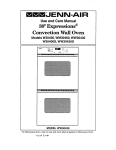
SECTION 2. COMPONENT
ACCESS
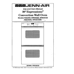
OVEN DOOR REMOVAL
The following are instructions to access,
repair and replace components of the slide-in
.
range.
The unit is more accessible if it is removed
from the installed position
procedures begin.
--
Open the oven
door as wide as
possible.
before servicing
,
IMPORTANT
I
DISCONNECT
FROM POWER SOURCE
BEFORE SERVICING APPLIANCE.
[
I
.
CONTROL PANEL ASSEMBLY
Place an 1/8"
pin in the hole
on the right and
left door hinges,
see Figure 2-1,
Remove the
screws from
each side with a
PhiLlips screwdriver. Remove
Electrical components can be accessed by
removing the control panel.
the lock plate
from each side,
Figure 2-1
To remove the control panel, open the oven
door as wide as possible. Remove the three
screws from the top of the control panel and
the three screws at the bottom of the con-
4.
Raise the oven door up to a broil stop
position. In this position, it will be
against the 1/8" pin.
trol panel. Grasp the control panel by
placing hands on the right and left sides of
the panel, pull out and down to disengage.
5.
Grasp the door toward the top on both
sides. Lift the door up and out to remove.
For JJW Models:
SERVICING OVEN DOOR
1. To remove the control panel, open the
door as wide as possible. Remove the
four screws from the bottom of the
control panel. Grasp the control panel
by placing hands on the right and left
sides of the panel, lift up and out to
disengage from upper flange.
2.
3.
Place the panel on the top oven rack
(cover with a cloth to prevent scratching) for component testing.
With the control panel pulled forward,
access is now available to the following
components: Control Assembly, Clock,
High Limit Thermostat, Cooling Fan,
Door Latch Mechanism and Motor.
1.
Lay the oven door on a protected surface
with the inner door panel facing down.
2.
Remove three screws from lower trim.
Remove trim piece.
3.
Slide outer-door glass down to disengage from top trim. Remove.
4.
Remove three screws from top oven
door trim. Remove the two 3/8" nuts
from the door handle bracket.
5.
Lift up and off. This will disengage
side trim as well.
6.
Remove the oven window pack by removing the 3/8" nuts from the insulation
retainer.
16009721
COMPONENT
©1999 Maytag Appliances Sales Company
ACCESS
the
2-1
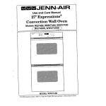
For JJW Models:
3.
1. Lay oven door on a protected surface
with the inner door panel facing down.
To reassemble the oven door, reverse the
procedures for disassembling.
COOLING FAN ACCESS
2.
3.
4.
Remove the three screws at the top and
the three at the bottom of the door, see
Figure 2-2,
To access the cooling fan, remove two 1/4"
hex screws from the bracket which the fan is
mounted on. Tilt motor and bracket to
Grasp the door assembly at the bottom
and lift the assembly off the front door
glass.
allow it to pass through main back panel.
Remove the two center screws holding
the center bracket in position.
Oven cavity components consist of: bake
and broil elements, oven light assembly,
convection motor, oven cavity, and oven
sensor,
OVEN CAVITY COMPONENTS
Oven Sensor Removal
Remove two 1/4" hex screws, pull oven
sensor into oven cavity to gain access to the
electrical quick connector.
To reassemble, use a probe and attach the
probe to the quick connector, Guide it
through the insulation to ensure the connector does not contact the oven cavity. Contact
could damage the connector.
Figure 2-2
5.
6.
Once the center bracket is removed you
will see two screws securing the trim to
the glass. Remove these screws.
Remove the two screws holding the left
and right side brackets in position.
Return to the original position, reattaching
with the 1/4" hex screws.
Bake Element Removal
Remove the two 1/4" screws.
Pull the bake
7.
Slide the front door glass out of the
frame.
element into the oven cavity to access
electrical wiring.
8.
Reverse the procedure to reassemble.
Broil Element Removal
OVEN DOOR HINGE REPLACEMENT
1.
Remove two screws from oven inner
door panel that mount into the lower
portion of oven door hinge assembly.
2.
Remove the four 1/4" hex screws. Pull broil
element into oven cavity to gain access to
the electric wiring. Reattach by returning to
the original position and fastening with four
hex screws.
Grasp and lift
oven door hinge assembly
upward and slide down to disengage
upper tabs from the door panel.
16009721
COMPONENT
©1999 Maytag Appliances Sales Company
ACCESS
2-2
Oven Light
3.
Bulb can be replaced or accessed by turning
the lens counterclockwise to remove the
Grasp the front flange of the oven liner
and gently pull forward to remove oven
liner from insulation and structure.
entire oven light. The socket can be removed
by depressing the spring clips from the rear
of the light socket end pushing it into the
oven cavity.
NOTE: When replacing oven cavity, use
pieces of sheet metal on sides and top of
oven liner to allow cavity installation
without tearing or removing insulation.
A new oven light socket can be inserted and
snapped into position by depressing the
spring clips and reattaching in the original
position.
When the cavity is within two inches of
being in place, remove the sheet metal.
Convection
Motor
Assembly
,
To access the motor assembly, remove the
three 1/4" hex screws from the convect
cover. Remove the cover. Remove three
additional 1/4" hex screws that secure the
convect motor assembly. Pull convect
motor assembly into the oven cavity, disconnecting the electricat quick-connect.
Reattach by returning to original position
using reverse procedures.
OVEN VENT/SMOKE
OVEN HINGE POCKETS
.
Remove oven door following the steps
previously described in section on Oven
Door Removal.
Remove hex screws from the lower front
closure.
3.
From each side of the range, remove two
1/4" hex screws.
4.
Replace components
and reassemble.
ELIMINATOR
Remove oven vent and smoke eliminator
,
by using tabs on bottom of smoke eliminator, turning counterclockwise to disengage the locking ears from the inner
insulation retainer.
2.
To remove the smoke eliminator, pull
down end align locking ears with notches
in oven cavity.
Reattach by reversing above procedures.
OVEN CAVITY
.
.
All internal oven cavity components
must be removed prior to oven cavity
removal.
Remove the five 1/4" hex screws from
the front flange of the oven liner. (Three
screws will be on the top and two on the
bottom.)
16009721
@1999 Maytag Appliances Sales Company
COMPONENT ACCESS
2-3
160(;9721
01999
Maytag Appliances Sales Company
COMPONENT
ACCESS
2-4
SECTION 3. TROUBLESHOOTING
Test Access
The test mode can be accessed by holding the stop time key down at
power up or by holding the stop time key down for 10 seconds within 5
minutes of power up mode, No other key can be pressed before the
stop time key, that would block the test mode access.
Test Exit
Exit the test mode by pushing the cancel key or test will self-terminate
after 16 seconds from the last key command chosen.
Test Function
Test mode is perfomed by pushing a keypad and testing for an output
response. When the keypad is released, the output is terminated and
the display will return to the "-" display. The following is a list of key
actions and responses.
NOTE:
1. Each time a key is pressed a tone will sound.
2. If there is a red dot on the IC-chip and the display board when you touch the oven light key,
the oven light will come on and a beep will occur. The beep is to let you know that there is
a good circuit, in case the light is blown. Also, when you press the fan speed key on a dual
speed downdraft, it will beep each time you touch the key. The first beep will be the high
setting, the second beep will be the low setting, and the third beep will be off.
Bake Key
Activates bake relay on the power relay board.
Broil Key
Activates broil relay on the power relay board.
Convect
Bake Key
Activates convect bake relay (CVBAK) on the power relay board.
Convect
Roast Key
Activates convect roast relay (CVRST) on the power relay board.
Oven Light Key
Activates oven light (OVLT) relay on the power
2 above.)
Probe Key
Activates the display on the control to display the probe temperature.
Timer Keys
Activates the display to show factory codes in the blue displayed
and oven temperature in red.
Clean Key
relay board.
(See note
digits
Activates blue display digits which shows the state of the door lock
switches and the status of the user selectable options. See charts on
page 1-2. NOTE: First (left) blue displayed digit is for user selectable
options code and the fourth (right) blue digit is for the door lock switch
status code.
TROUBLESHOOTING 3-1
16009721
O1999 Maytag Appliances Sales Company
Stop Time Key
Will activate the beeper 100% as long as the key is pressed. Also, it will
display the control I.D. # in the blue time digits and the power relay
board I.D. # in the red temperature digits.
Clock Key
Activates all display segments to light.
Cook Time Key
Activates any fault codes stored in the memory.
The time digits display
any fault codes for the membrane and control board. The temperature
digits display any fault codes for the power relay board. NOTE: If"FO"
is disDlaved, there has not been any fault codes sensed in that portion
of the svstem. Any stored fault code can be cleared to FO, after repairs
have been made, by entering the fast test and pressing both the cook
time and stop time keys for 5 seconds.
Digital Input Keys
Activates the display to show the same digit (0-9) that is pressed.
Temperature
Offset Change
Program bake above 500 °, repress bake pad and hold for 3-4 seconds,
the pad must be re-pushed within 3 seconds. The digital keys can be
used to set the offset between positive and negative(-). Entered values
are rounded to the next 5 ° increment. (Example: pushing key 3 will
display a 5 ° increment).
Clock and
Temperature
Change
The clock can be set to be displayed in 24 hour form. Also,
temperature can be displayed in degree "C". To access, hold either
timer keys down on power up. The two left digits will display the
format for the clock, the right digit will display "F" or "C." The display
can be toggled by pushing the bake or upper bake key to toggle the
clock. The temperature display can be toggled from F to C by pushing
the broil key or upper broil key on a double oven control.
16009721
O1999 Maytag Appliances Sales Company
TROUBLESHOOTING
3-2
User Selectable
Options Display Codes
Display
Code
Deg. C
24 Hour
Clock
F
X
X
X
X
X
X
X
X
X
X
X
E
D
Continuous
EOC
X
C
B
X
A
9
60 Hz
Reference
X
X
X
X
X
X
8
X
7
X
6
5
X
x
X
X
X
X
x
4
3
x
X
X
2
1
X
0
Door Lock Switch Codes
Display Code
Unlocked
Switch
Locked
Switch
Door Closed
Switch
7
closed
closed
closed
6
open
closed
closed
5
closed
open
closed
4
open
open
open
3
closed
closed
open
2
open
closed
open
1
closed
open
open
0
open
open
open
16009721
TROUBLESHOOTING
@1999 Maytag Appliances Sales Company
3-3
Fault Code
Problem
Components
to Check
F1
Power to element relay energized
during time of day display,
J2 harness shorted; If checks ok,
change (PRB) power relay board.
NOTE: For double oven only, change
second oven board.
F2
Over temperature sensed; over 620 °
sensed by control in time of day mode,
bake mode, or over 950 ° sensed in
clean mode.
Ohm SENSOR. If checks ok, change
)ower relay board.
"See chart for sensor value."
F3
Cooling fan on with no oven function
selected.
Ohm SENSOR, wire harness to sensor.
F4
Shorted oven sensor
Ohm sensor, wire harness to sensor.
F5
Power to element relays disabled in
cook mode.
1) Intermittent sensor or wire harness
connection.
2) Intermittent contact on PRB.
F7
Shorted key sensed for 32 seconds.
1) Membrane shorted..
2) Display board.
F8
Shorted meat probe alarm.
1) Probe jack or harness to probe jack.
F9
Door lock safety circuit on power relay
board.
PRB.
FF
Invalid temperature
Check sensor and harness, PRB.
F-
Communication
error between boards.
1) J2 harness, ohm wires end to end.
Harness ok, replace display board.
FC
Communication
error between boards.
J2 harness, ok, replace PRB.
reading on PRB.
Double Oven Only
FR
Second oven error sensed.
1) Check sensor and harness.
2) Replace second oven board,
MEAT PROBE
Type:
NTC Thermistor
PROBE RESISTANCE
Calibration:
9938 ohms (150°R)
VS. TEMR TABLE
Degrees E
Resistance
122
18963 ohms
150
9938 ohms
156.2
8846 ohms
165.2
7456 ohms
210,1
3886 ohms
16009721
TROUBLESHOOTING
O1999 Maytag Appliances Sales Company
3-4
TROUBLESHOOTING
Power Board
Voltage
J1-1
Resistance
Ref. Point
Comments
0.0 Vdc
J1-1
Signal Ground
J1-2
13.0 Vdc
J1-1
+12 Vdc Source
J1-3
21.2 VAC
J1-4
J2-1
5.0 Vdc
J1-1
J2-1
0.0 Vdc
J1-1
J2-2
5.0 Vdc
J1-1
J2-2
0.0 Vdc
J1-1
J2-3
0,0 Vdc
J1-1
J2-3
2,8 Vdc
J1-1
J2-4
0.0 Vdc
J1-1
Time of Day Mode
J2-4
2.8 Vdc
J1-1
Cooking Mode Active Oven 2
J2-5
1.2 VAC
J1-1
Serial Clock Line
J2-6
1.3 VAC
J1-1
Transmit Line
J2-7
2.5 VAC
J1-1
Receive Line
J2-8
T1 Secondary
Press Cancel 2
Press Cancel 1
Time of Day Mode
Cooking Mode Active Oven 1
Enable Line
J3-1
5.0 Vdc
J1-1
Probe Out
J3-1
<3.5 Vdc
J1-1
Probe In
J3-2
0.0 Vdc
J1-1
Signal Ground
J4-1
12.0 Vdc
J1-1
Down Draft OFF or High
J4-1
0.7 Vdc
J1-1
Down Draft ON Low
J4-2
12.0 Vdc
J1-1
J4-3
12.0 Vdc
J1-1
Down Draft OFF or Low
J4-3
0,7 Vdc
J1-1
Down Draft ON High
J5-1
12,0 Vdc
J1-1
+12 Vdc Source
J5-2
+12
Vdc Source
Open Pin
J5-3
12.0 Vdc
J1-1
Door 1 Closed
J5-3
0.0 Vdc
J1-1
Door 1 Open
J5-4
0.0 Vdc
J1-1
Door 1 Unlocked
J5-4
12,0 Vdc
J1-1
Door 1 Locked
J5-5
12.0 Vdc
J1-1
Door 1 Unlocked
J5-5
0.0 Vdc
J1-1
Door 1 Locked
J7-1
Enable Line
J7-2
Open Pin
J7-3
2,5 VAC
J1-1
16009721
Receive Line
TROUBLESHOOTING
O1999 Maytag Appliances Sales Company
3-5
Resistance
Ref. Point
Power Board
Voltage
J7-4
2.8 Vdc
J1-1
J7-5
0.0 Vdc
J1-1
J7-5
2.3 VAC
J1-1
Cooking Mode Active
Oven 2
J7-6
1.2
J1-1
Serial Clock Line
J7-7
0.0 Vdc
J1-1
J7-7
2.8 Vdc
J1-1
Cooking Mode Active
Oven 2
J7-8
0.0 Vdc
J1-1
Signal Ground
J8-1
12.0 Vdc
J1-1
+12 Vdc Source
J8-2
12.0 Vdc
J1-1
Door 1 Closed
J8-2
0.0 Vdc
J1-1
Door t Open
J8-3
0.0 Vdc
J1-1
Door 1 Unlocked
J8-3
12.0 Vdc
J1-1
Door 1 Locked
J8-4
Comments
Door Lock Limit
Time-of-Day
Time-of-Day
Mode
Mode
Open Pin
J8-5
12.0 Vdc
J1-1
Door 1 Unlocked
J8-5
0.0 Vdc
J1-1
Door 1 Locked
J9-1
1.9 Vdc
J1-1
Oven Probe
J9-2
J9-3
Open Pin
<3.5 Vdc
Cool Oven
J10-1
Open Pin
J10-2
<3.5 Vdc
J10-3
1.9 Vdc
Cool Oven
J1-1
16009721
Oven Probe
TROUBLESHOOTING
©1999 Maytag Appliances Sales Company
3-6
Control
Head
Voltage
Resistance
Ref. Point
Comments
J1-1
0.0 Vdc
J1-1
Signal Ground
J1-2
13.0
J1-1
+12 Vdc Source
J1-3
21.2 VAC
J1-4
J2-1
5.0 Vdc
J1-1
J2-1
0.0 Vdc
J1-1
J2-2
5.0 Vdc
J1-1
J2-2
0.0 Vdc
J1-1
J2-3
0.0 Vdc
J1-1
J2-3
2.8 Vdc
J1-1
J2-4
0.0 Vdc
J1-1
J2-4
2.8 Vdc
J1-1
Cooking Mode Active Oven 2
J2-5
1.2 VAC
J1-1
Serial Clock Line
J2-6
,1.3 VAC
J1-1
Transmit Line
J2-7
2.5 VAC
J1-1
Receive Line
J2-8
2nd Oven
T1 Secondary
Press Cancel 2
Press Cancel 1
Time-0f-Day
Mode
Cooking Mode Active Oven 1
Time-of-Day
Mode
Enable Line
Voltage
Resistance
Ref. Point
Comments
J7-1
Enable Line
J7-2
Open Pin
J7-3
2.5 VAC
J1-1
Receive Line
J7-4
2.8 Vdc
J1-1
Door Lock Limit
J7-5
0.0 Vdc
J1-1
Time of Day Mode
J7-5
2.3 VAC
J1-1
J7-6
1.2 VAC
J1-1
J7-7
0.0 Vdc
J1-1
J7-7
2.8 Vdc
J1-1
Cooking Mode Active Oven 2
J7-8
0.0 Vdc
J1-1
Signal Ground
16009721
Cooking Mode Active
Serial Clock Line
Time-of-Day
Mode
TROUBLESHOOTING
O1999 Maytag Appliances Sales Company
O_en 2
3-7
MULTIPLEXING
TST
Imm|
CIRCUITRY-WALL
I
DISPLAY
OVENS
._
J1
MAIN
POWER BOARD
SENSOR
!r
i
OVEN
J9
LOWER
OVEN
SENSOR
E_L
VCC REFERENCE -_
KEY M
OVEN
POWER
BOARD
(DOUBLE
OVEN ONLY)
DOOR
LOCK ,b
UNLOCK
m
VCC REFERENCE -.'
DOOR
M
LOCK
16009721
KEY
,a,
UNLOCK
m
TROUBLESHOOTING
©1999 Maytag Appliances Sales Company
3-8
POWER RELAY BOARD CONNECTIONS
TO
DISPLAy
BOARD
TO L1
_
TO
DOOR
J9
N
TO
OVEN
UGHT
D
NCor-USED
NEU'm_
N
OVEN
I SENSOR
"--_OVLT
T°
n.-..
r,i
TO
DISPLAY
BOARD
TO
UNIT
USED
BROIL
L.-.J
B_
TO
l
:..i
L2
DRLK _]_
CVRST []_
CVBAK _
BAKE
T
TO L2
UNIT
CONVECTION
MOTOR SLOW
SPEED
16009721
LOCK
MOTOR
COOL
1.2
TO
BAKE
--DOOR
01999
Maytag Appliances Sales Company
C_DUNG
FAN
TO
CONVECTION
MOTOR HIGH
SPEED
TROUBLESHOOTING
3-9
DISPLAY BOARD CONNECTIONS
DISPLAY BOARD
TO POWER
RELAY
BOARD J1
J
J2
)
MEMBRANE
SWITCH TAIL
TO POWER
RELAY
BOARO J2
CIRCUIT BOARD CONNECTIONS
l_l o,sPLAv.oA.o
IJ
I
ITO
DOOR
LOCK
CIRCUIT
N
BOARD
MEMBRANE
SWITCH TAlL
J10_
0OVLT
J'E
2
1
OR_I}
SClll_IIF
TROUBLESHOOTING 3-10
160G9721
@1999 Maytag Appliances Sales Company
MEMBRANE
CONNECTIONS
PAD
CIRCUIT
1
15to 4
2
14to 4
3
13to4
4
12to4
5
11to4
5
10to 4
7
9to4
8
8to 4
9
7to 4
0
6to4
LO BAKE
15 to 16
LO BROIL
14 to 16
LO CLEAN
13 to 16
TIMER ONE
14to 5
STOP TIME
13to5
CLOCK
12to 5
PROBE
11to5
OVEN LIGHT
10to5
TIMER TWO
9to 5
COOK TIM E
8to5
UPPER BAKE
10to3
UPPER BROIL
9to 3
UPPER CLEAN
8to 3
UPPER CONVECTION BAKE
7to3
UPPER CONVECTION ROAST
6to3
UPPER CANCEL
1 to2
LOWER CANCEL
1 to 17
Membrane Switch: The means to make a
switch contact, instructing the electronic
control system to perform a desired function.
The membrane switch is a simple set of two
contact surfaces containing conductive
material, one on the back layer of MYLAR
and the other on the front layer of MYLAR.
There is also a center section of non-conduc-
tive MYLAR material that has a hole
punched out of it at each switch contact
position. The thickness of the MYLAR
spacer determines the push force required
to close the contacts between the front
contact strip and the rear contact strip.
Typically, the push force required to close a
contact is 12 to 18 ounces.
16009721
TROUBLESHOOTING
O1999 Maytag Appliances Sales Company
3-11
POWER RELAY BOARD-DOUBLE
WALL OVEN
TO
DISPLAY
BOARD
TO L1
TO
UPPER
OOOR
LOCI<
TO
LOWER
DOOR
LOCK
IpRTOB
JACK
J1
N
J5
J8
J3
TO
NEUTRAL
J9
TO
OVEN
LIGHTS
J10
TO
| LOWER OVEN
.J SENSOR
/
TO
"m--_IuPPER
OVEN
]SENSER
DITOsPLAY
J2
TO
UPPER
BROIL
UNIT
JBOARD
TOuxILLARy
RELAY
BOARD
DRLK _--
L2
COOL D
CVRST _--
1.2
CVBAK
TO
UPPER
BAKE
UNIT
BAKE T
T
•_ TO L2
TO
CONVECTION
MOTOR
SLOW SPEED
TO
UPPER
DOOR
LOCK
MOTOR
-1
TO
COOLING
FAN
TO
CONVECTION
MOTOR
HIGH SPEED
SC116"nF
TROUBLESHOOTING 3-12
16009721
O1999 Mayteg Appliances Sales Company
AUXILLARY
RELAY BOARD-DOUBLE
WALL OVEN
TO L1
L1
TO
NEUTRAL
L1
N
To D
LOWER
DOOR
LOCK
MOTOR
N
DRLK
RELAY
TO
BOARD
TO
LOWER
BAKE
UNIT
L2
L2
-2
BROIL
T.°
OWER
BROIL
UNIT
TO L2
SC11TrlF
16009721
TROUBLESHOOTING
01999 Maytag Appliances Sales Company
3-13
CIRCUIT BOARD CONNECTIONS-DOUBLE
WALL OVEN
TO
UPPER
DOOR
LOCK
TO
LOWER
TO
L1
J1
J5
J8
J3
J9
TO
NEUTRAl
TO
OVEN
OVLT
JlC
NOT
USED
TO
UPPER.,dI.
BROIL-UNIT
J2
BROIL
\
CVBAKI CWSTIR
TO
UPPER
BAKE
UNIT
L.TO
TO t
CONVECTION
MOTOR
SLOW SPEED
_
I
MOTOR
Oo.N
G
FAN
TO
L1
N_I
TO NEUTRAL _
n_
u
N
DRLK
TO LOWER DOOR
LOCK MOTOR
TO
CONVECTION
MOTOR
HIGH SPEED
/
TO
LOWER
BAKE "91
UNIT
L2 BROIL
R:P =;=
t
TO
L2
8C111rNF
LOWER
TO
BROIL
UNIT
TROUBLESHOOTING 3-14
16009721
@1999 Msytag Appliances Sales Company
ELECTRONIC CONTROL PROGRAMMABLE
TEMPERATURE
1)
2)
3)
4)
OFFSET
CHANGES
CHANGE:
Program bake above 500 degrees F
Repress bake pad and hold for 3 to 4 seconds
The digital keys can be used to offset between 0 to 35 degrees in increments of 5
degrees.
The broil key is used to toggle between positive and negative offsets.
CLOCK AND TEMPERATURE
1)
2)
3)
4)
5)
CHANGE:
Hold either timer pad down during power up
The two left digits will display the format of the clock
The right digit will display F or C
Pushing the bake key will toggle the clock
Pushing the broil key will toggle the temperature from F to C
ELECTRONIC
CONTROL FAST TEST PROCEDURE
1)
Test Function:
Depressing a key pad allows for testing for an output
When the key is released, the output is terminated
2)
Test Access:
Hold the stop time key down at power up or for 10 seconds
within 5 minutes of power up.
3)
Test Exit:
Push the cancel key
Test will self terminate after 16 seconds from the last key
command chosen.
16009721
O1999 Maytag Appliances Sales Company
TROUBLESHOOTING 3-15
While in the test mode the following
outputs may be checked:
Bake Pad-
Press the pad in the test mode and the bake relay will be activated.
Broil Pad-
Press the pad in the test mode and the broil relay will be activated.
Convect Bake Pad- Press the pad in the test mode and the convect bake relay will be
activated.
Convect Roast Pad-Press the pad in the test mode and the convect roast relay will be
activated.
Oven Light Pad-
Press the pad in the test mode and the oven light relay will be
activated.
Probe Pad-
Press the probe pad in the test mode and the probe temperature
will
be displayed.
Timer-
Press the timer pad in the test mode and the factory codes will
appear and the oven temp will appear in red.
Stop Time Pad-
Press the stop time pad in the test mode and the beeper will be
activated and the control ID will be displayed in the blue digits
and the power relay board ID will be displayed in the red
temperature digits.
Clock Pad-
Press the clock pad in the test mode and all display segments will be
activated.
Clock Time Pad-
Press the clock time pad in the test mode and the last fault code
sensed in the system will be displayed.
Digital Input Pads-
Press the digital input pads in the test mode and the digit that has
been pressed will be displayed.
Clean Key-
Press the clean key pad in the test mode and the state of the door
lock switches and the status of the user selectable options will be
displayed.
TROUBLESHOOTING 3-16
16009721
01999
Mayteg Appliances Sales Company
USER SELECt'ABLE OPTION DISPLAY CODES
DISPLAY
CODE
DEG C
24 HR CLOCK
CONTINUOUS
EOC
60 HZ
REFERENCE
F
X
X
X
X
X
X
X
X
X
X
×
E
D
X
C
B
X
A
9
X
X
X
X
X
X
8
7
X
X
X
X
J1, J2 wire
harness
connection to
co ntro I
X
X
shorted, If
checks ok,
change control.
5
X
X
4
X
3
X
2
_1
X
X
X
0
TROUBLESHOOTING 3-17
16009721
€1999 Maytag Appliances Sales Company
DOOR LOCK SWITCH
CODES
DISPLAY CODES
UNLOCKED
SWITCH
LOCKED SWITCH
DOOR CLOSED
SWITCH
7
CLOSED
CLOSED
CLOSED
6
OPEN
CLOSED
CLOSED
5
CLOSED
OPEN
CLOSED
OPEN
OPEN
OPEN
3
CLOSED
CLOSED
OPEN
2
OPEN
CLOSED
OPEN
1
CLOSED
OPEN
OPEN
0
OPEN
OPEN
OPEN
To test the control the following
should be performed:
i
!4
For JJW Models
Bake Pad-
Touch the bake pad then touch the auto set pad within 4 seconds of
each other. The bake relay should engage and the element start to
heat. Listen for the relay and then check for heat from the element.
Broil Pad-
Touch the broil pad and then touch the auto set pad within 4 seconds
of each other. The broil relay should engage and the element start to
heat. Listen for the relay and then check for heat from the element.
Convect Bake Pad- Touch the convect broil pad and then touch the auto set pad within
four seconds of each other. The convect bake relay should engage,
the fan should come run on low speed, end the element start to heat.
Listen for the relay, the fan, and then check for heat from the element.
Convect
Roast Pad-Touch the convect roast pad and then touch the auto set pad within
four seconds of each other. The relay should engage, the fan should
start on high speed, and the element should start to heat. Listen for
the relay, the fan, and then check for heat from the element.
Drying Pad-
Touch the drying pad and then the auto set pad within four seconds
of each other. The fan should start and the element should start to
heat. Listen for the fan and check for heat from the element.
Clean Pad-
Touch the clean pad and then the auto set pad within four seconds of
each other. The relay should engage, the door lock motor energize,
and the door lock. Listen for the relay, the motor to energize, and
check the door to make sure it locks.
16009721
"[ROUBLESHOO'nNG
@1999 Maytag Appliances Sales Company
3-18
,
SECTION 4. WIRING
DIAGRAM
W2451
L1
I BK
N
L2
W
16009721
R
WtRtNG DtAGRAM
O1999 Maytag Appliances Sales Company
4-1
W2451
L2
L1
LIS'II
p_kl SW.
N
W/R
S[L $W,
TIM£R
>
3L
KSSTORrSXl
_lItt
_,
inT.)
"rIMER
RELAY
N_UTRAL-
r V/R
i;.l_,r
THERMOSTAT
i
THERMOS;TAT
_
llP(ATOq
A!
S£L 5W
"
LAT[H_# ITOPI
_1LNT
CY_
511.SW
"I" _AI_
TH_RMO_AT
CONTA(:TPI_
AT OVeN
T[tIP "F
SE'LECTOR
I
O
OF
OVZN
• _IERATIOH
OFF
R
L_ I
6_
CV
BAT
SETTINGS
OFF
8AI_
w--
1
S
2
6
O_K
OP_t4
BA_E
T(t'IP, OR
I
CLEAN
(_hIEC1
X
CL[AN
X
B[L_
I _J.OW
i
BROL
[ONVECT
X
,,'SCISSORLATCHSW. HAKES W_TH DOOR CLOSED
ZDMPONENT
SYHBOLSDO NOTREFLECTTRUE
CONFIGURATION
ALLFEEDLINECOLORSARE
NOTED(BLACK.
WVdTEAND RED).
ALL[OMPONENIS
_H_WN tN "nFF"POSITION
16009721
WiRiNG DIAGRAM
@1999 Maytag Appliances Sales Company
4"2
W27100
DOOR
ACTUAT[O
SWI TCH[S
L1
BROIL
[LEI/4E)IT
BAK£
EL [I_IENT
L2
,:I'_A_V'-I=
• ....
d
,____.
__1
m2_
9gA
I
'--i
i
J,..
Ml
_O_qAV[
I_JTLET
C(_IV_CT
_-_
HI
LIMIT
"
O00R
J ON _-_
®
_I1
(_.
ACTUAT[D
OVE_N
LIGHT
SWITCH
:-_:]
__J
--
NOTI C(:
I. DIS_kt[CT
RAN(_ _
FOAER
II_FI_(
REMOVING Wll_
¢OV(R.
2, IRFER ONLy TO F[AI_A[$
(_A_IpplEI_,
,_:_l_:
i
$,
"""_ _
°"_"
"_'
TM
ALL liES
PIIIQR TO OI_[CTION
S_RVlCING
CQI_TR_LS. II_IN_
PII_eLDA$
CAM _
IMP_O_R
AND _
CPIE_ATION.
VERIFY _
I_PI[ILA'_IGN AFT[.R SERVICING,
OCOR ACTUAT (O
SWITCH
16009721
WIRING DIAGRAM
@1999 Maytag Appliances Sales Company
4-3
W27200, W30100, WM27160,
WM27260
L.i
N
L_
JLUG_
I
//9
.....
_-
*e
€_cl
tw
_--'-_''I
N[UlI_
L_._L CC_S
r ................
I
I
€0C_OR r_/_
1_ nr_o
KS
/QAV
ROt
[LU4_T
_
IRJ*AIT
Ik_
[L[MU4T
F_
I[LMy
o
IRLA5
_U_
_l- ImIL, MmLIWLLAT
C0141110-|_
lqtlN51_ ¢T_-JTT _
lL1ff_t)
16009721
mlt_
WIRING DIAGRAM
@1999 Meytag Appliances Sales Company
4-4
W272000 W30100, WM27160,
WM27260
L1
RELCiY BOleRO
0
OlA_AH
P/N 208S_F
16009721
WIRING DIAGRAM
©1999 Maytag Appliances Sales Company
4*5
W27400, W30400, W30400R WM27460,
.t
WM30460
9
I
_.
I
fill__
• ai
I
•" /
t -._
iI
!l
illi ill>!
i 2 I"
I
_k
I
!i,0!
°
;i_ I ,°,''_,,"
ti_r-'-L-I
,T,
, it
'" _,7_
i._
_l
xt,..i,
,
ll!
ili
!
f
i
i
i
!
'io,
i{
I
-'I '
mT[l!
16009721
WIRING DIAGRAM
€1999
Maytag Appliances Sales Compnny
4-6
WW2460
II
E
\
e
il
s
i
16009721
i
!
©1999 Maytag Appliances Sales Company
WIRING DIAGRAM
4-7
WW27110,
WW30110
BLOCK
L1
r .......
,,-----_;
I
L ......
TH[RIdO5
,_A%.
•
BROIL
ELI_IEt_I
L 1_'4T
d
TAT
,._-_,
HI-LIMIT
SWITCIt
....
J
ELE
NT
LIMIT
O00fl
ACTUATED
s_2
T_C"_
. .o
I_
L_O_
L_
I
I
OFF
_'_L
CLEAN
[X_R
ACTUATE{}
SW_ TCH
i
NO_
OPEN
OF_H
L
SNIT_[5
UI_,OCKE0
NO/COU
I CLO3ED
I CLO_ED
N
LIHI[
R_LAy
I
r_R9 I_
_
I SEE NOT[
S[
CONTACTS
LIH(
1
I
I
.*I_A_ £
I _N
I SEE NOTE
_
_F
_TE
,
1
3
_-Ir_Tc_(c_Es so S_C_OS,
s S_CO_DS
_01L
ONLy.
54 S_C_OS
B_K[ ONLY,
2-HI
Ek_OIL-FU_.L
gATE,
LO BROIL-CY_.[_;
AT 80s RAT_.
3-FI_ST
40 MIN.
I*ll_
I/BROIL
OPEI_ATINC
ONLY CYCLIN_.
AFTER 443 _41N. LINE
I/_AK[
CYCLING
Ot_-y AT F'UL__ RATE.
16009721
WIRING DIAGRAM
(_1999 Maytag Appliances Sales Company
4-8
WW27210
LI
N
L2
REUIY BOgRD
_AH
16009721
P/N 2106938
©1999 Maytag AppliancesSales Company
WIRING DIAGRAM
4-9
WW27210
LI
ILa_(
N
!
L2
IBI
_qLUI .J
Nt.MI
@
SP£CF[
(Y(]£UT[SFOR
(_
Wt_G_A_H PIN 21O6938
160C9721
©1999 Maytag Appliances Sales Company
WIRING DIAGRAM
4-10
WW27430,
W27430R
WW30430,
WW30430P
|
0
16009721
WIRING DIAGRAM
@1999 Maytag Appliances Sales Company
4-11
WW27430,
W27430P, WW30430,
WW30430P
PlD_V
tm_mwlm
ml mw_
m
V.B,jt
_
LI
I,_lf
m
n_v
to ¢m,111_
w
L
P_
KLAV
_m
N=_O°
_
_,,_
m.
._.l_
_u
=_,._
_J-
_,",_'° . _
_q_
Ay
=_.
I_,,._-
WIRtFIG
DfAG_AH
P/N 20851_B
16009721
S_CFI(
CYCLE
RATES
FOR
[A_U
&S_OKO[H[_I
IS
WIRING DIAGRAM
_1999 Maytag Appliances Sales Company
4-12
JJW8527,
JJW8530,
JJW9527,
JJW9530, JMW8530,
JMW8527,
JMW9527,
JMW9530
i
i
ii
16009721
WIRING DIAGRAM
€1999
Maytag Appliances Sales Company
4-13
JJW8527,
JJW8530,
JJW9527, JJW9530,
JMW8530,
JMW8527,
JMW9527,
JMW9530
N
L1
1.2
REO
"_N$FORF4ER
_w
TO CO_d1ROL
IW__MGN
LI_LOO_O
MICRQWA'_
RE_PTACU[
B_UI'_YPLuG J3
I
BK
_KI AMp
I
t._.--r--_
J
I
.....
.m
PPP
OROL_UGD NEUIRAL
CHECI( LGP.,ALCOOES
RELAY
OBJEEN PLU_ JlO
..L
O..i
RNSO
m LIMIT
8K :.F'_
ikq OiL
PCB RELAY
Q
0
MOTO R
_J
O_fN
ELEMENT
f
..
_
_-_
LI_tT
CI_AL_;_E NT SYMBOLS00 NOT REFLECTI_U_ CONtqOURATION.
NJ. f_r_EDt._lE COLORSN_E ttOTEO _
W_ttTEIi _E_,
_4J_COMPONENTSSHOWN IM "l_P O_t REt.NCEDFO_TION.
'X" INOIC, ATI_5 R_L_y
CON'm0LS
MAg_
WtRIE COLORS'
R-REO
IIKdBLA_K
OFF
w_._
_p_E
G-GREEN
V-_IOt.ET
mL'_LU_
_aamovm
O*OR/_IGE
..L--
P_IF-.D
_t4h
D°m
CAM SVIRT CH
_',,,,,
x
x
M Zl0 •
[_ff at 21_'
_UU(I:
Ggfl k_'_r IL_xF
TIME D CONNECT
C_V_CT
CI_RUIT BO_R D
_
_:
u.,i _:
C_du €_du
x
I_
_.d
x
x
C_dm Otd_
cydm _,_*,
X
o.,,
_;
_ff at
_
_
_d
_r_.. d
X
x
X
X
o1_,_
Cdf at
BAKE
ROAST
x
o_
-_G3
_0_0
y-Y_OW
Cyd_
Cyci_
x
o_
X
I¢;_'_-_-d
X
X
X
SPECIFIC CYCLE RATES FOR EACH
MODE b SPECIFIC ELEMENT IS
AVAILABLE FROM SERVICE.
Z
o_o
O"
16009721
WIRING DIAGRAM
_1999
Maytag Appliances
Sales Company
4-14
JJW8627,
JJW8630,
JJW9627,
JJW9630
i
I
i
Z
m
a
I
I
I
I
i
I
I
j
_
I
I
o................
J
16009721
WIRING DIAGRAM
©1999 Maytag Appliances Sales Company
4-15
JJW8627,
NO_lm:
i, E_llm
UNB
mmum_r
JJW8630,
_
JJW9627,
JJW9630
iqum_t,
L1
N
L2
V4UTE
NED
m
may
To _ern_.
UAIL_XI_
mcAa_w
ION _
..........
mtmA_(D mUllt_
CHECKL_r_. C_
4=OaLINGr._q
l_w...
_a.._..ji_..
M
r,'
R
w
_- mm_11mw
c_ncL_
MA_(
w_
m
R
C_CU_ N
Om
N
x
•
x
•
x
•
x
x
_'_L
SPECIFIC
WIRING DIAGRAM P/N 208512F
16009721
CYCLE RATES FOR EACH
MODEbSPECIFIC
ELEMENT
IS
FROM SERVICE.
AVAILABLE
WIRING DIAGRAM
01999
Maytag Appliances Sales Company
4-16
JJW8530, JJW9530
- CANADA MODELS
!
!
I
I
I
I
I
I
I
I
I
I
I
I
I
I
I
I
0
16009721
WIRING DIAGRAM
@1999 Maytag Appliances Sales Company
4-17
JJW8530,
JJW9530
_
- CANADA MODELS
ca_
m
• X, IN0_GATES RELAy
CONTROLS M_
M_SO_
=
OPIER_.TI_N
OFF
Rv.opP oq W
m
DL6
I L1
! Ot_
SPECIFIC CYCLE RATES FOR EACI"
MODE 6 SPECIFIC ELEMENT IS
AVAILABLE FROM SER_
po_
U
OOORL_
L2
LIE
BR_L
LZ
B_(E
LZ
C/WE
L2RS 1
X
LZ
OVUGHT
LOCI
.q/L_
Lee= Door
Ewhd_
_ p_d
X
X
L_,_
BAKE
X
TIMED B/_JE
X
_'_:
Cv,_,, c_.
swk_h
x
x
COt_'vlECT BAKE
X
_;_:
c_*,. cyd. ,_'
_,.,._"_
x
x
T_MED COI¢_CT
CON_IECT
ROAST
BAKE
m" PH
X
X
CLEAN
X
BRGtL
X
O_ *t
O1_
_t _'
_10"
[_,d ng LO_
k
Q_
I Off
O_
I Oil
at
*t
_
*t
Zl0"
L_0'
POWER t_
;NO*
O_ _t
POM_ER _
Off
|t aO0"
cyd_
Cyd_
_
_j_
L_DO_
_ pad
X
X
CYd_
_
XK_or
_1
L_DO_
ll_t¢h
_ P_d
X
X
Cy_u
Cyd_
X
X
X
X
X
16009721
x
L _k D__ _d
r.v_4t_h
WIRING DIAGRAM
@1999 Maytag Appliances Sales Company
4-18