1
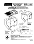
EXPRESSIONS
WUENN-AIR
DUAL FUEL COOKTOP 403
WEST
FOURTH
STFtEET,
flORTHeflE3NTON
tAS0208
IMPORTANT: Installation should be performed only by a Jenn-Air Authorized Servicer or other qualified installer. Read safety
precautions in the Use & Care Manual before using this appliance.
imensions shown in beth inches and centimeters.)
•
31 7/8" +1
[80.96 ¢m]
9/16" _:1/16"
[52.23 cm]
7/8"
22.54 crn_ 36.67
2 1/4 ° MIN.
GAS CONNECTION
AXIS
-'7
I
8 7/8"
[22.54 ¢m]
[2.54 ¢m]
MIN.
CLEARANCE
[5.71
5 13/16 °
[ 20.64.
20.30
cm]
CUTOUT
DIMENSIONS
cm]
SELECT
ARE CRITICAL
APPROPRIATE
DUCT CUTOUT
(SEE DUCTI NO
OeTUO.
I NSTRUCT
=
32 3/8"
[82.23 cm]
IONS. )
-
i
•
[11.75
"I
co
_]
cm]
_[4.4.4 cm]
TO
1/2" NPT EXT.
THREADEDNIPPLE
N
FOR COOLING PURPOSE.
1
[31.76
cm]
• Side Clearance - Unit may be safely installed as near as 2" (5.08
cm) from a side wall if space limitations require. However, a side
clearance of at least 6" is recommended for optimum ventilation.
INSTRUCTIONS
TO INSTALLER:
SAVE
THESE INSTRUCTIONS
FOR FUTURE REFERENCE
8101 P289-60
(ol -98-o0)
Location Of Your Jenn-Air Appliance
Preparation Of Countertop
Locatethis appliance away from combustible materials such
as window curtains and combustible wall decorations. The
minimum horizontal clearance between the edge of the
appliance and adjacent combustibleconstruction is:
• 0.75 inches (1.90 cm) at rear;
• 2 inches (5.08 cm) at sides
The cutout in the countertop intowhich the appliance is to be
installed should be prepared according to the cutout
dimensions given on page 1 of these instructions.
CAUTION: Cutout dimensions are critical. Dimensionsmust
be measured and cut accurately to within + 1/16" to ensure
proper fit.
These minimum clearances pertain to vertical surfaces
between the countertop level and a level 18" above the
countertop.
..............................
/
Important Installation Suggestions:
1. Chamfer all exposed edges of decorative countertop
laminate to prevent damagefrom chipping.
/
2. Slightly radius corners of cutout and file to insure smooth
edges and prevent corner cracking.
3. Rough edges, inside corners which have not been rounded
/'
18"
j
an ,orce
the
4. Unit must be supported on all four sides by the countertop
and countertop must be supported within 3" of edge of
laminate.
cutout.
(45.7_
1 _._
2.
Installation Of Appliance
ART_19215-030
Figure 1: Minimum Horizontal Clearance
Follow accompanying
This applianceisdesignedtoalwaysbeventedoutdoors.This
appliance should be ducted separatelyfrom other vented
appliances.
NOTE:These are not recommendedclearances,but rather
the minimum allowable clearances. Overall performance of
your cooktop will be enhanced by providing a 6" or greater
clearance on either side of the unit.
This appliance is designed for use with the gas appliance
Installing Cabinetry Over Your Cooktop
pressure regulator provided.
The installation of this appliance must conform with local
codes or, in the absence of local codes, with the latest edition
of the National Fuel Gas Code, ANSI Z223.1 USA or current
CAN/CGA-B149INSTALLATIONCODE.
Observethe following clearancesto overhead cabinetry.
t
_
ducting instructions carefully,
This applianceis designedto operate at a pressureof 5 inches
of water columnon natural gasor, ifconverted for use with LP
gas (propane or butane), 10 inches of water column. Make
sure this appliance is supplied with the type of gas for which
B _
This
appliancewas adjusted at the factoryfor usewith natural
it is designed.
gas. If,
type
of in
gas,
theall
future,
of the
thisconversion
applianceadjustments
isto be used described
on a different
on
Figure
2: MinimumClearancestoOverheadCabinetry
pages4 and 5 must be made by a servicetechnician or other
qualified person before attempting to operate the cooktop on
that gas. Naturalgas should besupplied to the appliance at a
line pressure between 6 and 14 inches of water column or, if
converted for LP gas, between 11and 14 inches.
A = 30 inches (76.2 ¢m) minimum vertical clearance
between cookingsurface and combustibleconstruction
or metal cabinets above the appliance. This clearance
may be reducedto not lessthan 24 inches by protecting
the underside of the combustible material or metal
cabinet above the cooking surface with not less than
1/4-inch insulatingmillboard covered with sheet metal
not less than 0.0122-inchthick.*
B = 13 inches (33.0) maximum depth of cabinets installed
abovecooking surface.
WARNING: If the pressure of the gas system supplying
this applianceexceeds 14"W.C., an external regulator(not
provided) must be installed in the gas line to reduce the
systempressureto no morethan 14" W.C.Failuretodo this
can result in excessive gasflow and explosion.
Make sure your appliance is suppliedwith the type of gas for
which it is adjusted and that the gas is being supplied within
the appropriate pressure range.
CAUTION: Avoid use of cabinets above cooktopfor storage
to eliminatepotential hazard of reaching over open flames,
*Jenn-Air Over-the-Rangemicrowaveovens (model#M418 and M438)have been listed by ULfor use over Gas and ElectricRanges, When properly
installedat aminimumheightof66 inchesfrom the floortothe top ofthe microwave,the clearanceto the cookingsurfaceatthe centerwill be 13-3/4inches.
2
Connecting
Appliance
To Electricity
Connecting
Wiring Information
Electrical
1. Install a manual shut-off valve in an accessible location
the gas line external to this appliance for the purpose
shutting off gas supply to this appliance.
2. Install the appliance pressure regulator supplied with th
Proper Electric Supply
You must provide an adequate electrical supply system as
required for your cooktop. All wire connections must be in
accordance with local codes and properly insulated. Check
with local utility for voerning electrical codes and ordinances,
In the absence of local electrical codes, the National Electrical
Code, NFPA No. 70, governing electric cooktop installations
must be followed. A copy of the National Electrical Codes,
NFPA No. 70, can be obtained by writing to:
NATIONAL FIRE PROTECTION ASSOC.
Batterymarch Park
appliance to the threaded gas inlet of the manifold pip(
taking care to observe proper direction of gas flow throug
the regulator. Tighten to 20 to 30 ft.-Ibs, of torque.
3. Connect the inlet of the appliance pressure regulator to th
shut-off valve using a 1/2" NPT pipe nipple of appropriat
length and additional pipe fittings, as required.
Use an approved pipe joint compound that is resistant to th
action of LP gas on all external pipe threads when makin
these connections.
A three-wire, single phase, A.C. 120/240 volt 60 cycle
electrical system (properly circuit protected to meet Local
Codes of NFPA No. 70) must be provided. Unit must be
properly grounded in accordance with local wiring code. The
chart below recommends the minimum circuit protector and
Quincy, Massachusetts
02269
wire size if the appliance
is the only unit on
the circuit. If smaller
sizes of wire are used, the unit efficiency will be reduced and
a fire hazard may be created. It is advisable that the electrical
wiring and hookup be accomplished by a competent
electrician.
APPL
_A,CEPR______
REGULATOR, SUPPL IEO
(OBSErvE
DIRECTION
OFGASFLOW
ARROW)I
I
UNmN
PI PE
HI PPLE
_LEXI
BLE.--_.f_
CONNgCTO
(5 FT. MAX)
FLARE
ADAPT
UN IONoR-_
SHUT-OFF
VALV
GAS
F_._
6
_-
___
_
_--GAS
SHUT-OFF
VALVE
_
P I PE
__
_1"/--1/2"
NPT
P_PE
1/2"
NPT_
Figure 4: Alternative Gas Connections
A new, A.G.A.-certified,
flexible metal appliance connector
4.) The flexible connector should have a diameter of 1/2" flare
union adapter is required at each end of the flexible connector.
CAUTION:
not attempt
to attach tothe
connector
may be usedDo
to connect
this appliance
the flexible
gas supply
(figure
directly to an external pipe thread.
"
.__
t_
_2" ,_T
APPL IANCE
Remove attachmentscrew and cover from junctionbox.
Connect BX cable power supply to knockout in side of box.
Make wire connections, push wires into box. Re-attach cover.
Consult local codes for proper power hookup. (Figure 3).
._
I
I
FLARED_
WIRE SIZE,
AWG
12
10
8
8
60
}
ADAPT
RECOMMENDEDMINIMUM
12.0 - 14.9
To Gas Supply
A TRAINED
SERVICEMAN
OR GAS APPLIANC
INSTALLER
MUST
MAKE
THE
GAS
SUPP[
CONNECTION. Leak testing of the appliance shall t
conducted by the installer according to the instructior
given.
The neutral of this unit is grounded to the frame through the
green grounding wire. If local conditions do not permit
grounding of the neutral, untwist or disconnect the green wire
and connect the green wire to ground in accordance with local
codes. Connect the white neutral to the service neutral.
K.W. RATING
CIRCUIT PROTECTION
ON SERIAL PLATE
IN AMPRES
0- 4.9
20
5.0- 6.9
30
7.0- 9.9
40
10.0 - 11.9
50
Appliance
,_/
IMPORTANT
(_
Apply a non-corrosive leak detection fluid to all joints and
fittings in the gas connection between the supply line
in
the valve
rangeand
if the
connections
were
shut-off
range. Include
gas disturbed
fittings andduring
joints
Box
4×
fittings and Check
installation.
connections
for leaks!
will bubbles
indicate appearing
a leak. If around
a leak
appears, turn off supply line gas shut-off valve, tighten
connections, turn on the supply line gas shut off valve, and
retest for leaks, Never test for gas leaks with an open flame.
CABLE j/
F lure 3
3
NOTE: In Canada, gas utilization codes prohibit use of street
elbows. Use standard pipe elbows and make modifications to
these instructions as necessary,
Step 3: Trim a small piece of masking tape to the size of
a dime and affix it over the end of a 5/16" nut
driver.
Pressure Testing
Step 4: Firmly press the nut driver over the orifice spud
(figure 5) and loosen spud by turning
counterclockwise. Carefully lift nut driver out of
burner throat. Orifice spud should be captured in
the recess. Repeat this step for each burner.
This appliance must be isolated from the gas supply piping
system by closing its individual manual shutoff valve during
any pressure testing of the gas supply piping system at test
pressures equal to or less than 1/2 PSIG (2.5 k pa).
This appliance, as well as its individualshutoff valve, must be
disconnected from the gas supply piping system during any
pressure testing of the system at test pressures in excess of
1/2 PSIG (3.5 k Pa).
ALUMfNUM
VENTURI
5/16 mNUT DRIVER
When checking for proper function of the appliance pressure
regulator, make certain pressure of natural gas supply is
between 6 and 14 inches of water column or, if converted for
LP gas, between 11 and 14 inches.
BURNER BASE
P_ECE
TAPE
STUCK
Or MASK_NC
TO END
oF DRIVER
I GNI TEn
Converting Appliance For Use With LP
Gas
ORIFICE
WARNING
SPUD
Figure 5: Removalof Orifice Spud
Propane conversion is to be performed by a JENN-AIR
AUTHORIZED SERVICER (or other qualified agency) in
accordance with the manufacturer's instructions and all
codes and requirements of the authority having
jurisdiction. Failure to follow instructions could result in
serious injury or property damage. The qualified agency
performing this work assumes responsibility for this
conversion,
I
Electrical power and gas must be turned off prior to
conversion.
WARNING
This appliance was adjusted at the factory for use with natural
gas. To convert it for use with LP gas (propane or butane), both
of the following modifications must be performed:
A.
Replace all orifice spuds
Step 1: Remove the grates and burner heads.
Step 2: Remove aluminum venturi tube.
Step 5: Locate the LP orifice spud packet taped to the
underside of the burner box. The spuds have
small numbers stamped on the side. This
number codes the orifice diameter and its
correct
burner
location.
The following
illustrations show correct LP orifice spud
location for 4 burner and 5 burner models,
respectively.
of the nut driver, press an LP orifice spud into the
recess so that it is snugly captured.
Step 6: With the masking tape still in place in the recess
Step7: Carefully install the orifice spud in the
appropriate burner throat by turning clockwise to
tighten. Tighten to a torque of 15 to 20 inch-lbs.
Step 8: Replace cylindrical aluminum venturi tubes.
Replace burner heads and grates. Index each
grate to its burner pan.
Step 9: Save the orifices removed from the appliance for
future use.
Installation of LP Orifice Spuds
With a quarter, engage slot and rotate cap 1/8 of a tL
counterclockwise. To remove cap, turn cap over and reinst_
=
_
°
.
(_
L
P""
"_ _
NaturalSetting
LP Setting
Figure8: Conversionof Harper-Wyman
Appliance Pressure Regulator
0
//
ART #9215-033-0
00
_
After conversion, steps A and B have been completed, che¢
the appearance of each burners' flame at the Hi and L
small, review all steps to make sure they were complete
correctly.
settings against figure 9. If the flames appear too large or to
Figure 6
B. Invert Cap in Appliance Pressure Regulator
(See figures 7 and 8.) With the appliance installed,
regulator is located on the underside of the burner box on
right hand side at the inlet to the gas manifold. Identify
make of appliance regulator on the unit and follow
the
the
the
the
,.P"-"_gs
' ',
,/
I_1o
,._
2.,
I;
-
5 6
CAP
R._
I
_'--_A ND PIN
J
CONVERTE
NAT
_jl
r
LP
RER.ACE
PININC,
AP.
,_
_
FINGER
PRESSURE
TO_
PIN
APPLY
SIDEWARD
_ _
Figure 7: Conversionof Maxitrol
Appliance Pressure Regulator
I '±
__
_
7 8
Figure 9: Flame Appearanceat Hi and Lo
To Convert Appliance For Use With
Installation of Natural Gas Orifice Spuds
Natural Gas
This appliance is equipped for electronic auto-reignition by
If this appliance has been converted for use with LP gas, each
of the following modifications must be performed to convert
the unit back to natural gas.
means of a spark igniter located at the side of each burner. The
burners are designed to light at any valve rotation that admits
sufficient gas flow to support a flame and to automatically
re-light following a momentary loss of flame due to a draft or
other adverse condition. This feature is provided as a
convenience and is not intended as a safety feature.
A.
Replace all orifice spuds
Perform Steps 1 through 4 on page 4.
For Step 5: Locate the colored brass natural gas orifice
spudsthatwereoriginallyinstalledinthisappliancebefore
its conversion for use with LP gas. Observe the color of
each of the spuds and note the correct burner location for
each spud as shown in figure 10.
Complete Steps 6 through 9 on page 4 to complete the
installation of natural gas main spuds in their correct
locations.
use. They will be needed if this appliance
converted for use with LP gas.
This appliance has no air shutters, making adjustment of
primary air unnecessary. The burners are designed to provide
optimum aeration of all gases without air shutters. When
operating properly, burners should produce clearly defined,
even blue flames. If the flames have yellow tips or are hazy
and otherwise appear to have insufficient air, obtain the
services of a qualified service technician.
is again
Save the orifices
removed from
the Orifice
appliance Spuds
for future
Installation
of Natural
Gas
/
BURNER
Right Front
Right Rear
NATURAL
GAS
PROPANE
ALL GASES
BURNER RATE BURNER RATE
LO RATE
(BTU/HR)
(BTU/HR)
(BTU/HR)
12,000
6,500
8000
4500
1,600
800
Q
CAUTION:
cover
control
knobsobjects.
or surrounding
control
surface
withNever
utensils,
towels
or other
Never obstruct
Q
free
passage
the control
knobs.
The toknob
openings
haveair
been
sized past
to properly
control
air entry
the interior
of
Q
the appliance during operation.
Q
©
ART #9215-032-0
Figure 10
B.
___
Invert Appliance Pressure Regulator Cap
With the appliance installed, the regulator is located on the
underside of the appliance at the inlet to the gas manifold.
Identify the type of regulator on the unit and follow the
instructions in the appropriate illustration. (See figures 7
and 8).
After Steps A and B have been completed, check the
appearance of each burners' flame at the Hi and Lo settings
against figure 9. If the flames appear too large or too small,
review all steps to make sure they were completed correctly.