1
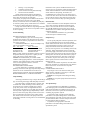
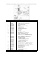
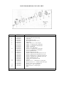
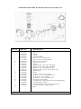
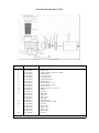
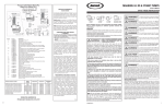
Jacuzzi
Magnum, RC, LR, Cygnet
®
Owner’s Manual
E-1451
WARNING – (For cord & plug connected units).
To reduce the risk of electrical shock do not use an
extension cord to connect unit to electrical supply;
provide a properly located outlet.
7. CAUTION – (For pumps with a 25 ft. (7.62m cord).
This pump is for use with storable pools only. Do
Inspection
not use with permanently installed pools. A storable
Examine the equipment when received. Notify your
pool is constructed so that it may be readily
dealer or carrier of any damage or missing parts. Verify
disassembled for storage and reassembled to its
that equipment is of size and model specified.
original integrity. A permanently installed pool is
constructed in or on the ground or in a building such
that it cannot be readily disassembled for storage.
Important Safety Instructions
8. CAUTION – (For pumps with/without 3ft. (.91m
When installing and using this electrical equipment,
cord). This pump is for use with permanently
basic safety precations should always be followed,
installed pools and may also be used with hot tubs
including the following:
and spas if so marked. Do not use with storable
1. READ AND FOLLOW ALL INSTRUCTIONS.
pools. A permanently installed pool is constructed
2. WARNING – To reduce risk of injury, do not permit
in or on the ground or in a building such that it
children to use this product unless they are closely
cannot be readily disassembled for storage. A
supervised at all times.
storable pool is constructed so that it may be readily
3. WARNING – (For cord & plug connected units). Risk
disassembled for storage and reassembled to its
of Electrical Shock. Connect only to a grounding type
original integrity.
receptacle protected by a ground-fault circuit9. WARNING – (For hot tub and spa pumps). Do not
interrupter (GFCI). Contact a qualified electrician if
install within an outer enclosure or beneath the skirt
you cannot verify that the receptacle is protected by a
of the hot tub or spa, unless so marked.
GFCI.
10. SAVE THESE INSTRUCTIONS!
4. WARNING – (For cord & plug connected units). Do
Installation Location
not bury cord. Locate cord to minimize abuse from
Locate pump as close to pool/spa as possible,
lawn mowers, hedge trimmers and other equipment.
preferably in a dry, well ventilated area away from direct
5. WARNING – (For cord & plug connected units). To sunlight. It should be on a hard, level surface. Give
reduce the risk of electric shock, replace damaged
consideration to:
cord immediately.
Before installation, be sure to read all instructions
and warnings carefully.
Refer to product dataplate(s) for additional operating
instruction and specifications.
should be on a hard, level surface. Give consideration to:
6.
the pump discharge. The valves are essential for pump
1. Drainage – away from pump.
2. Ventilation of pump motor.
3. Access for future servicing and winterizing.
4. Protection from the elements.
Pumps without strainer bodies are designed for
flooded suction (all suction fittings and suction piping
below water level) and will not self-prime.
Consequently, the pump must be installed at an elevation
that is below water level when pool or spa is filled;
however, if suction line valves are installed, the pump may
be closed for priming. Keep vertical distance to a minimum
if you choose to mount pump above water level.
Pumps with strainer bodies are self-priming but should
be mounted as close to the water level as possible or below
for ease in priming.
General Plumbing
FOR SOLVENT WELD CONNECTION
Rigid or flexible PVC pipe can be used. Pipe ends
should be clean and free of any flash cause by the cutting
operation. Be sure that the proper adhesive is used on the
type of pipe specified.
Recommended Adhesives – These are examples only
and are not intended to restrict brands.
PVC – PVC Joint
PVC – PVC Joint
Uni-Weld Pool-Tite 2000 Uni-Weld Pool-Tite 2000
Suregard Flex 20
Suregard Weld-All No. 5
IPS Weld-On 705
IPS Weld-On 794
Note: A primer will assure that adhesive joints are superior.
Suregard P-3000 has a purple tracer to qualify in areas
where codes specify a primer must be used.
Caution: We recommend that you consider climatic
conditions when applying adhesives. Certain atmospheric
situations, such as high moisture content, make adhesive
action of certain glues less effective. Check the
manufacturer’s instructions.
FOR THREADED CONNECTIONS
Use only Teflon tape or equivalent on threaded
plumbing connections. Other pipe compounds may damage
threads. We do not recommend the use of silicone or
petroleum based compounds. DO NOT OVERTIGHTEN –
HAND TIGHTEN PLUS ½ TURN IS SUFFICIENT.
maintenance if the system is installed below deck level.
Suction valves are essential for priming all pumps without
strainer bodies installed above water level. Pumps with
strainer bodies are self-priming, nevertheless, we
recommend the use of check valve in the suction pipe at
or below the water level if the suction lift is more that five
feet or if the dry suction is more that ten feet long. Keep
the valve in the suction line fully open during operation.
Electrical Data
Refer to information on motor nameplate fo electrical
service data. All motors should have fused disconnect
switch or circuit breaker. Be sure wire size is sufficient
for pump HP and distance from power source. Wiring
should be done in accordance with applicable codes by a
competent electrician.
We recommend the installation of a ground fault
circuit interrupter for maximum safety.
Pump Start Up
Do not operate pump until it has been primed as water
acts to cool and lubricate the seal. For pumps without
strainer bodies and locater above water, close suction line
valve and fill pump with water in order to prime. For
pumps with strainer bodies and located above water,
prime by removing strainer cover and filling strainer body
with water. Pumps located below water level will selfprime if all piping is also below water level. After pump
has been primed, energize motor and open all suction and
discharge line valves. It may take some time for pump to
remove air from suction lines. If no flow is observed in
five minutes, stop the motor and re-prime. If the pump
fails to operate, check for air leaks. Refer to Trouble
Shooting section.
After about ten minutes of operation, check the return
fittings for air bubbles. A continuous flow of air indicates
leaks in suction line. Locate and correct any leaks
immediately.
CONTROLLING THE OUTPUT
Keep the gate valve in the suction line fully open
during operation. Should it be necessary to control the
output, use a valve in the return line.
Caution: Do not retighten strainer Ring-Lok during
operation.
Pump Plumbing
Caution: Do not operate pump with closed suction or
Suction pipe should be as large or larger that discharge discharge valves.
pipe. Avoid using suction pipe small that pump connection.
Keep the piping as straight and short as possible, and Two-Speed Pumps
of suitable size. Avoid connecting an elbow directly into
the pump inlet (use a length of straight pipe to allow a
Two-speed models are recommended in a swimming
proper entry for the water). Arrange horizontal runs to
pool when high speed is needed for maximum filtration at
slope upward to the pump to prevent high spots that could peak periods and whenever turbidity levels are high. At
form air pockets. Support the pipe independently so that it other times, switch to low speed. For backwashing and
places no strain on the pump. Keep as much of the suction vacuuming, high speed is required.
line as possible below the water level to reduce priming
In spas and hot tubs, use high speed to attain full
time. Install valves and unions in the pump suction and
performance in the hydro-therapy mode. At other times,
return lines to facilitate servicing. Valves are recommended such as filter/heat cycle mode, use low speed. Low speed
for throttling
provides sufficient flow to activate most spa heaters and
provides sufficient flow for filtration.
In jetted tubs, use high speed to attain full
performance in the hydro-therapy mode and use low
speed mode to prime.
PARTS DIAGRAM FOR MAGNUM, MAGMUN PLUS, & MAGNUM FORCE MODELS
FIG. NO.
PART NO.
1
2
3
42-2828-06-R
39-2579-02-R
47-0358-03-R
47-0434-01
16-1097-04-R
43-3036-01-R
03-0856-02-R
03-2009-04-R
47-0112-00-R
31-1609-06-R
12-1069-02-R
12-1124-05-R
12-1126-03-R
14-4231-07-R
47-0232-54-R
14-4206-08-R
06-0157-05-R
06-0165-05-R
06-0167-03-R
10-1462-07-R
05-3800-01-R
05-3818-01-R
05-3819-00-R
05-3820-07-R
05-3854-06-R
05-3855-05-R
10-1502-09
47-0364-47-R
02-1392-02-R
02-1366-04-R
02-1393-01-R
02-1368-02-R
14-1293-24-R
42-2886-05-R
42-2867-08-R
DESCRIPTION
Cover retainer
Strainer cover 7/88
O-Ring – Units after 7/89
O-Ring 5-5/8 x 6-1/8 x ¼ - Units prior 7/89
4
Strainer basket with Flapper
4a
Flapper
5
Magnum body strainer 2” with plugs
5a
Magnum Force body
6
Plug O-Ring (2req’d)
7
¼” plug with 47011200 O-Ring
9
Base motor support assembly 2/88
9a
Motor support
9b
Motor base
10
Dowel pin ¼ x 1-¼ SS 4/89
11
Square ring
*12
Hex wash. hd. A8 – 16 x 1¼ SS (2 req’d)
13
Diffuser, ½ HP full rate & ¾ HP uprate
Diffuser, 5-¼ fit. 1-½ – 3 HP full rate & 2 HP uprate
Diffuser, 4.875 fit. ¾ - 1 HP full rate 1 – 1-½ HP uprate
14
Eye seal
15
Impeller, ½ HP full & ¾ HP uprate 4-3/16” Dia.
2 HP, full rate 5-3/16” Dia.
1-½ HP full rate 2 HP uprate 5-1/8” Dia.
3 HP full rate 5-1/8” Dia.
1 HP full rate 1-½” HP uprate 4-¾” Dia.
¾ HP full rate 1 HP uprate 4-¾” Dia.
16
Shaft seal (replaces 10139004)
17
O-Ring
18
Seal housing, 5-¼ fit. 1-½ – 3 HP full rate, 2 HP update
Seal housing, 4-9/16 fit. ½ HP full rate, ¾ HP uprate
Seal housing, 4-7/8 fit. ¾ - 1 HP full rate 1-½ HP uprate
19
Motor housing bracket
20
PL hex capscrew 3/8 – 16 x 7/8 (4 req’d)
21
Pump mounting nut 2/88
22
Mounting nut rachet
23
Motor, see chart pg. 57 for selection
24
42-3555-03
Motor support kit GE to Century
25
24-0138-07
Case/Base assembly
NOTE: 3 each required for diffuser 06-0165-05-R. 5 each required for diffuser 06-0167-03-R
PARTS FOR MODELS RC, URC, RTC, URTC
FIG. NO.
PART NO.
1
3
4
5
6
7
8
9
03-2001-02-R
31-1609-06-R
47-0466-02-R
14-4244-02-R
12-1036-02-R
47-0462-06-R
14-4206-08-R
06-0157-05-R
06-0163-07-R
06-0164-06-R
06-0166-04-R
10-1462-07-R
10-1463-14-R
10-1464-13-R
05-3806-05-R
05-3800-01-R
05-3801-00-R
05-3802-09-R
05-3803-08-R
05-3805-06-R
05-3852-08-R
10-1389-07-R
02-1389-07-R
02-1351-01-R
02-1610-08-R
14-1266-35-R
14-1293-24-R
10
11
12
13
14
15
16
DESCRIPTION
2” Case/Flange Assy.
Drain plug with 47-0112-00 O-Ring
Square ring
Base fastener kit 2” 4/90
Base assembly (with Fastn. Kit #5)
Square ring
Diffuser, bolt 8-16 x 1 ¼ SS (2 Req’d)
Diffuser, ½-1 HP full rate & 1½ HP uprate
Diffuser, 1½ -2 HP full rate & 2 HP uprate
Diffuser, 3 HP full rate
Diffuser, “New” 2HP full rate
Eye seal, ½-1 HP full rate & 1½ HP uprate
Eye seal, 1½-2 HP full rate & 2 HP uprate
Eye seal, 3 HP full rate eff.
Impeller, 5URC UR. 3-5/8” dia.
Impeller, ½ HP full rate & ¾ HP uprate 4-3/16” dia.
Impeller, ¾ HP full rate & 1 HP uprate 4-1/16” dia.
Impeller, 1 HP full rate & 1½ HP uprate 4-25/64” dia.
Impeller, 1½ HP full rate & 2 HP uprate 4-9/16” dia.
Impeller, 3 HP full rate 4¾” dia.
Impeller “new” 2 HP full rate 5” dia.
Shaft seal
Bracket, 4½” fit ½ - 1 HP full rate & 1½ HP uprate
Bracket,4-29/32” fit 1½ - 3 HP full rate & 2 HP uprate
Bracket, 5-5/32” fit “new” 2 HP full rate
Bracket bolt ¼ - 20 x ¾ SS (8 req’d)
Motor bolt 3/8-16 x 7/8 SS (4 req’d)
Motor
PARTS DIAGRAM FOR LR, LR9 LRX, LRT, LR3, LR6, LR25, LVL
FIG. NO.
PART NO.
DESCRIPTION
1
2
3
4
42-1678-09-R
39-0753-04-R
47-0352-41-R
16-0240-02-R
16-1052-15-R
16-0307-02-R
03-1957-24-R
16-0985-01-R
47-0258-53-R
10-1462-07-R
05-3760-09-R
05-3759-02-R
05-3821-06-R
05-3853-07-R
10-0002-06-R
02-1388-08-R
14-3970-04-R
14-4238-00-R
14-3971-03-R
14-4239-09-R
31-1609-06-R
23-4856-00-R
23-4718-08-R
23-4863-01-R
12-1109-04-R
Strainer nut
Strainer cover
O-Ring
Basket LR
LVL Strainer Basket
Strainer case assy. With plugs LR
Case assy. With 1 plug and O-Ring LVL
Strainer case assy. 9.00 disch.
Square ring 6 x 1/8 x 1/8
Seal ring
Impeller for 5LVL, 5LR, ½ HP, 3.45D, #9838
Impeller for 7LVL, 7LR, ¾ HP, 3.73D, #9838
Impeller for 1LVL, 1LR, 1HP, 4.0D, #9838
Impeller for 15LVL, 16LR, 1½ HP, 4.22D, #1135D
Mechanical seal
Bracket
PL. Hex 10 – 24 x 1¼ (6 req’d) LR
SS Hex 10 – 24 x 1¼ (6 req’d) LRDV & LVL
PL. Hex nut 10 – 24 (6 req’d) LR
SS Hex nut 10 – 24 (6 req’d) LRDV & LVL
Plug with 47-0112-00 O-Ring
Cord with plug 6ft. F/LRX, LR6, 6ft. with 3 prong grounded plug
Cord with plug 25 ft. F/LR25
Cord with plug #12-3 115v 3ft. all LR3, twist-lock plu
LVL/LTVL with 8587-4105 motor support
Motor
5
5a
6
7
8
9
10
11
12
13
15
16
17
PARTS DIAGRAM FOR CYGNET
FIG. NO.
PART NO.
DESCRIPTION
1
2
3
4
5
6
7
8
9
10
11
12
13
14
15
42-1678-09-R
39-0753-04-R
47-0352-41-R
16-1052-15-R
16-1105-04-R
47-0112-00-R
31-1609-06-R
14-4231-07-R
14-1301-02-R
14-0722-01-R
14-0727-06-R
14-4206-08-R
06-0150-07-R
10-1462-07-R
05-3936-08-R
05-3937-07-R
05-3939-05-R
05-3940-02-R
10-0002-06
47-0361-48-R
11-1520-00-R
90-1069-15-R
90-1069-23-R
90-1069-31-R
90-1069-49-R
12-1135-02-R
Strainer RingLok
Strainer cover
Strainer O-Ring 4-7/8 ID x 3/16 THK
Strainer Basket
Case with 2” plugs
Plug O-Ring (2)
Plug with O-Ring (2)
Base dowel pin
SS Bolt 3/8-16x2 - ½ (4)
SS Lock washer – 3/8 (4)
SS Nut 3/8-16 (4)
Diffuser screws 8 – 16 x 1¼” (2)
Diffuser
Eye seal
IMP ¾ HP
IMP 1 HP
IMP 1½ HP
IMP 2 HP
Mechanical seal
O-Ring 6” ID x 3/16 THK
Seal plate
Motor ¾ HP
Motor 1 HP
Motor 1½ HP
Motor 2 HP
Base assy.
16
17
18
19
20
Winterizing
Consult your dealer for advice on winterizing your
equipment if freezing temperatures occur in your locality.
His knowledge of your equipment makes him the best
qualified source of information. Follow his
recommendations, and if these include draining the filter
system, proceed as follows:
1. If your system does not contain a filter, proceed to
step2.
A. For sand filters: BACKWASH for 3 to 5
minutes and set dial valve to WINTERIZE.
B. For cartridge filters: Clean the filter element and
store in a dry place.
2. Drain system by loosening drain plugs (drain plugs
will drain without completely removing the plug
from unit) and/or removing pipe caps.
Water Chemistry
A proper and consistent use of chemicals is
necessary to maintain clean, sanitary water, prevent a
spread of germ infection and control the growth of algae
which can spoil the appearance and enjoyment of your
pool or spa.
Chlorine is the most commonly used chemical to
provide clean, sanitary water. Either dry or liquid chlorine
(calcium or sodium hypochlorite) can be used which
should be added daily as it is dissipated by dirt and germs
as well as be the sun and wind.
It is also important that the correct level of acidity or
alkalinity of the pool water be maintained. This is the pH
of your pool with pH 7.0 being neutral. Readings above
7.0 are alkaline and below are acid. A desirable range is
7.2 – 7.4.
Pump Maintenance
1. Motors are self-lubricating – no lubrication required.
2. Clean hair & lint strainer if you have a strainer body
pump.
3. Visually inspect motor for blockage of air vents on
motor shell. Remove any debris after breaker off.
4. Shaft seals may become worn and must be replaced if
leakage is observed.
3.
4.
5.
6.
Motor windings burned out.
Defective starting switch inside single-phase motor
Disconnected or defective wiring
Low voltage
MOTOR DOES NOT REACH FULL SPEED
1. Low voltage
2. 2 speed model set on low speed
3. Motor windings connected for wrong voltage on
dual voltage model.
MOTOR OVERHEATS (Protect trips)
1. Low voltage
2. Motor windings connected for wrong voltage on
dual voltage model.
3. Inadequate ventilation
PUMP DELIVERS NO WATER
1. Pump is not primed
2. Closed valve in suction or discharge line
3. Leakage or air into suction system
4. Impeller clogged
LOW PUMP CAPACITY
1. Valve in suction or discharge line partly closed
2. Suction or discharge line partly plugged
3. Suction or discharge line too small
4. Pump running at reduced speed (see above)
5. Plugged basket in skimmer or hair and lint strainer
6. Dirty filter
7. Impeller clogged
8. Wrong rotation (3 phase only)
LOW PUMP PRESSURE
1. Pump running at reduced speed (see above)
2. Wrong rotation (3 phase only)
3. Discharge valve or inlet fittings closed too much
HIGH PUMP PRESSURE
1. Discharge valve or inlet fittings closed too much
2. Return lines too small
3. Dirty filters
Cleaning
NOISY PUMP AND MOTOR
Switch power off. Close valves in suction and return
1. Plugged basket in skimmer or hair in lint strainer
line. Unscrew strainer Ring-Lok counterclockwise and
remove the strainer cover from hair and lint strainer and lift 2. Worn motor bearings
3. Valve in suction line partly closed
out strainer basket. Clean and replace the basket. Take care
4. Suction line partly plugged
to seat basket properly. Clean O-Ring and re-lubricate with
5. Vacuum hose plugged or too small
petroleum jelly if necessary. Clean O-Ring seats on cover
6. Pump not supported properly
and strainer. Refit cover and strainer – hand tighten only –
and open valves. Put pump back into operation.
LEAKAGE OF WATER AT SHAFT
Caution: Do not retighten strainer during operation.
1. Shaft seal requires replacement
Service & Repair Parts
Refer all service to your local dealer as his knowledge AIR BUBBLES AT INLEY FITTINGS
of your equipment makes him the best qualified source of
1. Leakage air into suction line at connections or valve
information. Order all repair parts through your dealer. Give
stem
the following information when ordering repair parts:
2. Cover gasket of hair and lint strainer needs cleaning
1. Unit nameplate data.
3. Restriction in suction line
2. Description of part.
4. Low water level in pool
Trouble Shooting
MOTOR DOES NOT START
1. Disconnect switch or circuit breaker in OFF position.
2. Fuses blown or thermal overload open.
Locked motor shaft.
NOTE: If the recommendations in the Trouble
Shooting portion of this manual do not solve your
particular problem(s), please contact your local dealer
for service.
JACUZZI BROS.
®
Division of Jacuzzi INC.
LIMITED WARRANTY
Jacuzzi Bros. Division (JBD) warrants its new products to be free of defects in materials
and workmanship for a period of 1 year from date of installation or 3 years from date of
manufacture, whichever comes first. Jacuzzi Bros. Also provides additional warranty coverage on
specific products as specified herein.
Magnum Plus and Magnum Force pumps (excluding pump seal, o-rings, square rings,
strainer basket, and lid) are warranted to be free of defects in material and workmanship for a
period of 3 years from date of installation or 4 years from date of manufacture, whichever comes
first.
JBD’s warranty obligation with regard to equipment not of its own manufacture is limited
to the warranty actually extended to JBD by its suppliers. Performance of equipment is further
warranted to be accordance with stated ratings when properly installed under normal conditions
of operation.
This warranty extends only to the original retail purchaser and only during the time in
which the original retail purchaser occupies the site where the product was originally installed.
Requests for service under this warranty shall be made by contacting the installing JBD
dealer (point of purchase) as soon as possible after the discovery of any alleged defect/ JBD will
subsequently take corrective action as promptly as reasonably possible.
JBD at its discretion may replace or repair any product that fails under this
warranty after inspection by an authorized company representative or after JBD has received the
product at our factory. Replacement or repair cannot be made until after the product is inspected.
All charge or expenses for freight to and from the factory, removal and reinstallation of the
product, or installation of a replacement product are the responsibility of the purchaser.
THIS WARRANTY SUPERSEDES ANY WARRANTY NOT DATED OR BEARING
AN EARLIER DATE. ANY IMPLIED WARRANTIES WHICH THE PURCHASER MAY
HAVE, INCLUDING MERCHANTABILITY AND FITNESS FOR A PARTICULAR
PURPOSE, SHALL NOT EXTEND BEYOND THE APPLICABLE WARRANTY PERIOD.
Some states do not allow limitations on how long an implied warranty lasts, so the above
limitation may not apply to you. IN NO EVENT SHALL JBD BE LIABLE FOR INCIDENTAL
OR CONSEQUENTAL DAMAGES. Some states do not allow the exclusion or limitation of
incidental or consequential damages, so the above may not apply to you.
This warranty does not apply to any product which has been subjected to negligence,
alteration, accident, abuse, misuse, improper installation, vandalism, civil disturbances, or acts of
God. The only warranties authorized by JBD does not authorize other persons to extend any
warranties with respect to its products, nor will JBD assume liability for any unauthorized
warranties made in connection with the sale of its product.
THIS WARRANTY GIVES YOU SPECIFIC LEGAL RIGHTS, AND YOU MAY
ALSO HAVE OTHER RIGHTS WHICH MAY VARY FROM STATE TO STATE.