1
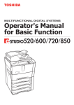
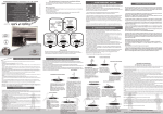
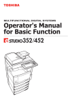
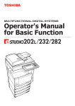
440 Rutherford St. P.O. Box 847 Goleta, CA 93117
1-888-888-4079 • FAX 805-692-2525 • www.supercharger.com
Installation Instructions
SUPERCHARGER
‘99-’00 Mazda Miata 1.8L
999-200
999-205
999-210
999-215
w/
w/
w/
w/
power steering, w/ AC
power steering, w/ out AC
out power steering, w/ out AC
out power steering, w/ AC
TOOLS REQUIRED:
17mm, 14mm, 13mm, 12mm, 10mm, & 8mm sockets
10mm, 12mm, and 17mm open end wrenches
Deep sockets (14mm or 9/16”, 10mm)
Phillips and Standard screwdriver
5mm Allen wrench
Paper clip
Timing light
READ THESE INSTRUCTIONS THOROUGHLY!
Follow the instructions STEP-BY-STEP, and your
installation will be trouble free. If in doubt, CALL 1888-888-4079. We suggest that as you proceed
through the installation, you should read a few steps
ahead in the instructions so you are certain to catch
all notes and warnings.
ATTENTION SUPERCHARGER INSTALLER! Before
proceeding with the installation, it is important to
know that to validate the 2 year, 100K warranty on
your new J/R supercharger, you must completely fill
out the Moss Motors / Jackson Racing warranty card
that comes in every kit, including serial number which
is on a small white ‘bar code’ label on the body of the
supercharger. Write down all of the numbers which
appear on that label in the appropriate space on the
warranty card. Be certain to do this now because
once your supercharger is installed, it may be almost
impossible to retrieve that serial number.
WARNING: Once the installation is complete,
CHECK AND RECHECK ALL fuel system connections for possible leaks before operating the vehicle.
91-octane gasoline (or higher) is required when running a supercharger.
During this installation process, you will reuse some
parts or hardware and not reinstall others. It is recommended that you make space for those that you
will reuse, and a separate space for those that you
will not reinstall. In addition, you should save the
parts that will not get reused in case you ever have
reason to convert the engine back to stock.
Enclosed is a set of labels that we suggest you use
to label the electrical connectors that you will be
unplugging.
SPECIAL NOTE: Jackson Racing Supercharger
Systems are designed to be installed by individuals
with good mechanical sense and with the proper
tools. Use your discretion--if you are not a competent
mechanic, do not attempt this installation.
999-200
NOTE: Will not work with factory strut tower
braces.
1
Revised 1/07
Figure 1.4
1.0 DISASSEMEMBLY
1.1 Disconnect your Miata’s battery.
1.2 Release the air flow meter harness 5-pin connector by pressing the locking tab on its clip.
Remove the stock air flow meter from the air box by
removing the two 10mm headed retaining bolts and
then remove the Air Temperature sensor with its rubber mounting grommet from the Air filter box. And
finally remove the air filter assembly complete with
intake snorkel, these parts will not be reused. Move
the air flow meter to a safe place on a worktable.
1.3 Remove the molded rubber elbow and hard
plastic tube that lead from the throttle body to the
airflow meter.
behind the lump. If your hose does not have this
restrictor there is one provided in the hose bag of
the supercharger kit. Save this restrictor for step
#7.8.
1.5 You can do this entire procedure without losing too much coolant, there is no need to drain
your cooling system. In the upcoming step you
will be removing the throttle body and Idle
Control Solenoid (ICS) valve. If you remove the
small coolant hoses that run to the ICS valve
(which is mounted under your throttle), you can
drain the excess coolant into a coffee can or
such. Rest the can on the steering rack down in
front of the engine and aim the hoses into the
can as they drain. Once the flow stops, you can
remove the throttle body without making a mess.
1.4 Remove the crankcase vent hose that is
2.0 THROTTLE BODY
attached to the front of the cam cover. (Figure
1.4). This will not be reused. Also, find the small
2.1 Remove the throttle body (FIGURE 1.4) by
restrictor inside the rubber hose that ran from the releasing the two electrical connectors (one has
cam cover to the Mazda plastic crossover/intake
a spring wire, one has a plastic lever clip), the
tube. It can be felt as a lump in the straight sectwo small coolant hoses on either side of the
tion of the hose near the end. Persuade it out by lower Idle Control System (ICS) valve, and the
gently clamping the hose with a pair of pliers just three nuts and one bolt. TIP: THE SPRING
999-200
1/07
2
HOSE CLAMPS FROM MAZDA ARE BEST
REMOVED BY APPROACHING FROM THE
SIDE WITH NEEDLE NOSE PLIERS. GRASP
ALL THREE TANGS AT ONCE AND COMPRESS
THEM TOGETHER. THIS IS EASIER TO DO
WITH THE THROTTLE BODY ALREADY LOOSE
FROM THE INTAKE MANIFOLD. Plug the
coolant hoses with a screwdriver, golf tee, or pencil to prevent the leakage of coolant (OR - keep
the hose ends above the radiator cap level to prevent leakage). Release the throttle cable from the
throttle shaft spool. Release the Throttle Position
Switch harness by lifting the small wire clip that
runs around the rectangular base of the connector. If the throttle body gasket tears as you
remove it (even though it is made of metal, it can
tear), you will need to clean off the old gasket
from both surfaces, the throttle body and the
intake manifold. Carefully use a knife or the backside of a hacksaw blade to scrape the mounting
surfaces clean. DO NOT SCRATCH OR MAR
THE MOUNTING SURFACES IN ANY WAY.
Immediately below and behind the throttle body
on the intake manifold is a steel support brace in
the shape of an inverted “L” attached by four
12mm headed dolts. Remove the brace and resecure the wiring harness ground wire attached
at that point with one of the 12mm headed bolts.
front and side of the dummy throttle body.
2.5 Do not connect the ICS electrical connection
until after the next step.
2.6 Wiring Harness Modifications:
Locate the main engine wiring harness on the left
side of the engine (as viewed from the front of the
engine) where it runs between the intake manifold
and cam cover. Cut the strap of the white plastic
harness anchor at the front and release the firewall end of the harness by gently prying the
release tab on the securing clamp located near
the rear engine lifting eye. Starting at the forward
point where the four black/yellow wires come out
of the harness, cut the black tape binding the
plastic corrugated tubing so that you can access
the wires within. Locate the wiring branch of the
ICS valve connector and follow the wires to the
main harness. Pull these two wires (purple and
orange) back free from the main harness about 45 inches so that you have enough slack to plug
the connector in the repositioned ICS valve. Cut a
length of the small diameter corrugated tubing
supplied in the kit to cover the wires on the ICS
branch from the plug to the main harness with an
additional inch of tubing to protrude into the main
harness tubing. Locate the wiring harness branch
for the Throttle Position Switch (TPS) that origi2.2 Moving to a worktable, remove the idle air
nally connected at the throttle body connector.
control (ICS) valve from the bottom of the throttle Pull these wires back to about 4 inches from the
body by removing the two
firewall. If the construction of your particular harPhillips head screws. Use a
ness is such that you cannot free all three wires
good quality screwdriver and
(light green/red, green/black and black/pink) all
be careful not to strip the
the way back, cut the offending wire (usually light
Phillips head screw. If you
green/red) and pull the wires with the connector
cannot loosen a screw with
back free. Then strip about 1/4 inch of insulation
the screwdriver, use a small
of each end of the cut wire and using the Crimp
set of pliers from the side.
connector supplied; insert a stripped end into
Carefully separate the two
each end of the connector. Crimp (collapse) each
units making sure not to tear
end of the connector onto stripped ends, making
the gasket. The gasket will want to stay with the
sure that the connection is secure. With the crimp
Mazda ICS valve.
connector installed on the wire, shrink seal the
ends of the Crimp connector by heating it with a
2.3 Take the Dummy Throttle body from your
heat gun or a hair blow dryer. Using some of the
supercharger kit and install the Mazda Idle Air
small diameter corrugated tubing provided, cover
Control Valve (ICS) from step 2.2 on the bottom,
the TPS harness branch. Wrap the main harness
rotating the ICS valve 180 degrees so that the
and branches with the roll of tape supplied in the
electrical connector now points to the rear of the
kit, in the same manner as the factory had.
engine. Use the Mazda original ICS to Throttle
Reattach the harness at the rear harness clamp
body gasket.
by snapping it back in place and at the front by
using a new Ty-Wrap strap through the base of
2.4 Install the Dummy Throttle Body and ICS
the white plastic anchor. You can now plug in the
valve assembly back onto the intake manifold in
ICS valve connector by routing the harness
the same position as the standard Mazda throttle branch under and around the intake manifold to
body. Use the original gasket or the1104 adhesive the ICS valve. The TPS connector will be plugged
on the mating surfaces and the two new 8mm x
in after installation of the supercharger and throt40mm long bolts provided in the lower two holes
tle body assembly.
on the dummy throttle body. Reconnect the
coolant hoses to the brass coolant barbs on the
999-200
1/07
3
Figure 3.1
2.7 Locate the ICS blanking plate and take it over
to your Mazda throttle body. Use the 1104 sealant
between the blanking plate and the Mazda throttle
body. Install the blanking plate onto your Mazda
throttle body using the two new Phillips head
screws supplied in the kit. Insert the shaft of a
Phillips or cross head screwdriver into the ends of
the coolant connections. Gently twist the connections 90 degrees counter clockwise to their standard position so that they point in the same direction as the throttle body inlet. Do not worry if you
kink the coolant connections, you are only moving
them out of the way and they will not be reused.
3.0 BELT DRIVES
3.1 NOTE: CARS WITH POWER STEERING: You
will be re-arranging your power steering bracket
components per figure 3.2. Located above the
power steering pump on the black plastic timing
cover, remove the 10mm headed bolt that secures
the small bracket for the Crank Angle Sensor cable.
Remove the bracket and reinstall the 10mm-headed bolt. Referring to figure 3.1, remove the slot
bracket and pillow block by removing bolts “A”, “C”,
and “D”. Take the flat idler pulley bracket from your
kit and trial fit it to the assembly per figure 3.2. You
will be moving the pillow block and bolt “D” to
behind the power steering stamped steel bracket
(pillow block’s dome facing upward). This makes
999-200
room for the flat idler pulley bracket. The upper
support for the repositioned long bolt “D” comes
from a new adjustment bracket included in the kit.
The new adjustment bracket is attached to the
stamped steel power steering bracket using a new
bolt/washer/nut assembly supplied in your kit. Make
sure to point this bolt with its head nearest the aluminum idler pulley and that this bolt goes through
the hole. The rearward hole is now used for the
relocated “D” bolt, which will be used to tighten your
drive belt. Note: The power steering pump must
be in its lowest position for this procedure.
4
1/07
3.2 When you are done with your trial fitting of the flat idler pulley bracket, take
this flat bracket to a workbench and
install the two nylon idler pulleys using
the bolts and Nylock nuts provided. Make
sure that the bolt heads point towards the
rear of the car.
3.3 Secure the idler pulleys firmly to the
flat bracket. Proceed to install the idler
pulley assembly onto the car per the procedure practiced during the trial fitting.
The final assembly (minus the pulleys)
should look like figure 3.3.
VERY IMPORTANT:
Check the clearance between the small
coolant hose that runs from the base of
the thermostat housing and the passenger side idler pulley. If the clearance is
less than ? inch between the hose and the pulley,
trim three quarters of an inch of length off of the
thermostat end of the small hose. Reinstall the
hose, reusing the spring clamp. By removing a
small piece of the hose end, the hose will be
pulled away from the idler pulley, avoiding any
damage during operation. This is a critical area
for attention since a hose failure could cause
severe engine damage. Not all cars need this
modification.
Figure 3.4
THE PINCH BOLT’S HEAD IF NECESSARY.
3.5 Pick the flat steel supercharger bracket from
the kit and slip the non-slotted end over the
power steering bolt. Reinstall the power steering
pump nut with the flat bracket pinched between
the nut and the cast power steering pump bracket
that is on the engine. When finished, rotate the
power steering pump as far down as possible
(the pulley will touch the AC compressor pulley if
so equipped). This will allow room for the supercharger to be installed and for the
belt to slip over the pulleys.
3.6 NON POWER STEERING
CARS: Locate your lower bracket
assembly from the kit. The end
with the small 90 degree bracket
mounts to the idler bracket (standard on AC equipped cars) or to
new idler bracket (supplied with kit
for non-AC, non-PS cars). Use the
new, longer 10mm bolt provided to
attach this bracket to the engine
(Review figure 3.4 for bolt location).
Figure 3.3
3.4 POWER STEERING CARS: Spin the power
steering pump pulley until the nut on the main
pump mounting bolt is visible. Insert a socket
wrench (deep 14mm) here and hold the rear hex
head with a 14mm box wrench. Remove the nut.
(item “B” in figure 3.1). VERY IMPORTANT:
MAKE SURE THAT THE DRIVER’S SIDE IDLER
PULLEY IS FREE TO SPIN. THE PINCH BOLT
THAT YOU INSTALL THROUGH THE PILLOW
BLOCK FROM THE REAR CAN INTERFERE
WITH THE BACKSIDE OF THE IDLER IF
INSTALLED INCORRECTLY (i.e. leaving out
the thick washer under the bolt’s head). TEST
THE ASSEMBLY BY TIGHTENING THE PINCH
BOLT FULLY AND SPINNING THE IDLER PULLEY. USE ADDITIONAL WASHERS UNDER
999-200
5
Figure 3.5
1/07
4.0 FUEL MANAGEMENT
4.1From the kit,
locate Jackson
Racing “PowerCard”
Digital Fuel
Management Module
(DFMM), it will
appear as a small
black plastic box with
6 wires coming out of
it. Using Velcro provided, you will be
attaching the
Jackson Racing
PowerCard to the
side of the factory
Engine Computer
Unit (ECU). The ECU is located directly above
the brake/clutch pedals.
PowerCard in the interior. To route the hard plastic
vacuum pipe to the engine compartment, you will
need a long narrow rod or screwdriver shaft approximately 24+” long. On the driver side of the engine
compartment you will find a rubber grommet where
the main wiring harness goes through the firewall.
From inside the engine compartment, carefully push
your long tool through the grommet. Have someone
watch from the interior so that you don’t drive the
tool through any vital parts other than insulation.
Once through, you can tape the hard plastic vacuum pipe to the tool and carefully pull it back through
the firewall. You should end up with a good weather
tight seal and your vacuum pipe tucked cleanly
away under the dash.
4.2 Locate the plug closest to the clutch/brake
pedal. There is a White/Red wire on this plug that
will serve as your 12volt power source. Clamp a TTap on this wire.
4.3 Locate the plug furthest from the clutch/brake
pedals. It is home to the 5 remaining wires used for
the Powercard installation. Find the Black/Blue wire
which is your ground wire and clamp on a T-Tap.
Next you will be locating the 4 injector wires. They
are colored as follows: Yellow/Black, Violet/Green,
Yellow/Red and a Yellow/Green. Clamp a “T” Tap
onto each of these 4 wires. Now plug the red wire
from the Jackson Racing PowerCard into the
4.5. Route the hard plastic pipe across the back of
the engine and across the valve cover. Connect this
hard plastic pipe to the vacuum fitting on the intake
manifold with the small, 90-degree adapter hose.
Connect the other end to the Jackson Racing
PowerCard by sliding the hard plastic pipe into the
silicone hose of the PowerCard.
4.6. Using the “Hook and Loop” material supplied
with the kit, attach the PowerCard to the side of the
ECU once the vacuum hose is connected.
5.0 SUPERCHARGER PREPARATION
White/Red wire. This will be your system 12v power.
Plug the black wire from your Jackson Racing
PowerCard into the Black/Blue wire. This will be
your system ground. Plug the 3 grey wires and 1
blue wire into the 4 remaining injector wires. It doesn’t matter in what order.
4.4 You will need to route a hard plastic pipe from
the intake manifold to the Jackson Racing
999-200
5.1 Working on a table or bench, set the supercharger in a position easy to work with. Be careful
not to bump the supercharger pulley in any way as it
can easily damage the front bearing. Install your
Mazda throttle body with the ICS blanking plate as
installed in step #2.7 and mount it to the supercharger using the new gasket or 1104 adhesive and
the two new 8mm x 35mm long bolts supplied in the
kit.
6
1/07
5.2 Locate your throttle cable bracket that is bolted
to your standard intake manifold and remove the
throttle cable by loosening the pinch nuts surrounding the cable end on either side of the bracket.
Once the nuts are loose, you can pull the cable out
of the bracket - the grommet will deform and let you
do this. Remove the throttle cable bracket by removing the two 10mm headed bolts. Unclip the throttle
cable from the firewall anchors. Begin rerouting the
throttle cable by looping the end behind the brake
master cylinder and laying its length along the driver’s side fender well.
6.0 SUPERCHARGER INSTALLATION
6.1 Remove the engine lift eyelet at the front of
the engine, just above the exhaust manifold by
removing the bolt using a 14mm socket. Install
the new flanged headed bolt supplied with your
kit into the boss on the side of your cylinder head.
Leave at least 1/2” of thread exposed on the bolt.
Remove the heat shield from the exhaust manifold. Make sure to spray the small bolts with WD
40 or such and let them soak for a bit to make
sure that they do not shear off during removal.
Spray your exhaust manifold nuts with
WD 40 or equivalent and let soak for ten
minutes, reapplying at the five minute
point. Remove the nuts from the two top
center exhaust manifold studs (#2 and
#3, counting from the front). Install the
exhaust manifold to supercharger bracket
over the two exposed studs. The third
hole on the bracket should be offset
upwards and away from the engine.
Reinstall and tighten the two nuts. Mount
rear bracket on the exhaust studs #2 &
#3 Reusing Mazda Exhaust Nuts.
Remove the counter sunk bolt and nut
which hold the main supercharger bracket to the small L-bracket attached to the
supercharger unit. Discard the nut, it is
for shipping purposes only. Locate the
jam nut from the appropriate hardware
bag (self locking prevailing torque nut:
M10).
5.3 Locate the black plastic Roto-mold elbow
from your kit. Check inside the elbow for any
debris and clean it out if necessary. You will be
placing the assembly into the position shown (Fig.
5.3) prior to installing the supercharger. Make
sure to install the 2.50” to 2.750” reducer hose to
the airflow meter end of this elbow prior to setting
it in place. This will greatly assist in air flow meter
installation. Also, install the 2.50” diameter hump
hose to the throttle body end of this plastic elbow.
Use the clamps provided to secure the hoses to
the elbow.
999-200
6.2 Bring the supercharger
over to the engine. Feed the
throttle body end into the
hump hose already installed on the plastic Air
flow meter to throttle body elbow (make sure to
slip a fully opened hose clamp over the hose
first). Orient the supercharger so that you can slip
the forward large “keyhole” in the bracket
attached to the supercharger over the bolt head
installed in step #6.1. Make sure that the bolt
moves up the respective vertical slot and seats
against the upper edge of the horizontal slot in
the bracket. Slide the supercharger towards the
firewall as far as it will go. Reinsert the counter-
7
1/07
using an open-end wrench. If you find that the
bracket/supercharger assembly collides with
your cam cover vent tube during initial installation, it means you did not leave enough threads
exposed on the main mounting bolt installed in
step #6.1. Retry it with the bolt further out.
6.3 Swing the flat lower bracket up into place in
front of the supercharger boss. Locate the small
stamped throttle cable bracket from your kit and
thread the new bolt through the throttle cable
bracket hole, through the spacer, through the
supercharger boss and through the flat steel
lower bracket. Secure with the locking nut and
bolt supplied. Make sure that the head of the
bolt is on the throttle bracket side of the assembly.
6.4 Route your throttle cable so that it is looped
back toward the firewall, routing the cable just
behind the driver’s side headlamp. Install the
cable’s threaded end into the small bracket
attached to the underside of the supercharger.
Make certain that the cable/grommet is fully
nested within the slot (this may require some
muscle – we made it tight so your throttle cable
won’t ever fall out). Open the throttle by hand
and insert the cable end into the throttle spool.
Make sure that the cable runs in the center of
the groove of the throttle spool. If it does not,
adjust the throttle cable bracket left or right until
it is centered in the spool’s groove. Have an
Lower Hole is slotted for adjustment of
supercharger mounting angle
sunk bolt removed earlier through the L-bracket,
through the main S/C bracket, and through the
hole in the exhaust manifold to S/C bracket. The
jam nut that goes on this bolt fits tightly between
the rear support bracket and the engine’s cam
cover. Use an open-end wrench and some
masking tape to hold the nut to the wrench while
you feed it into place. Start the countersunkhead bolt with your other hand and run the pair
down tight. Tighten down the front pinch bolt
999-200
8
1/07
rubber grommet that you earlier removed from
the stock Mazda air filter box into the 3/4” hole in
the base of the new Air Filter. Insert the grommet
from the backside so that the grommet’s flange is
on the outside of the filter base. The small hole
and boss in the air filter base will line up with the
horizontal hole you just removed the 6mm body
colored bolt from. Using the longer bolt provided
(M6 x 30mm, Allen head), attach the air filter
base/air flow meter assembly to the car using this
bolt (it mounts horizontally, through the air filter
base, the flying buttress, and into the Mazda captive nut on the flying buttress). Use thread-locking
compound. Make sure that the electrical connector on the air flow meter is still accessible for the
main wiring harness connector to be installed.
assistant operate the gas pedal multiple times
to confirm that the action is free and easy without binding or interference. Make sure that the
cable has a bit of “sloppy” slack with the gas
pedal released and that full throttle is available
when the gas pedal is fully depressed. If it does
not “flop” in the idle position, you will have trouble setting your idle speed. Make sure that the
cable is run in such a way as to allow for engine
movement from side to side. Make very certain
that all throttle cable mounting points are
secure - this installation area is critical for
safe operation of your car. This bracketry
has been carefully designed for correct
operation. It is your responsibility as the
installer to insure that it is bolted together
successfully without binding or interference.
7.4 Make sure that there is no chaffing or rubbing
anywhere along the plastic elbow assembly, even
though it is a very tight fit. Gently reposition any
brake lines that are pressing against the elbow.
Make sure all joints and clamps are secure - a
leak in this area will keep your car from idling
correctly. However, never over tighten your
clamps, they may break somewhere down the
road. Install the small piece of vacuum line supplied from the bypass block vacant nipple to the
‘small’ nipple on the plastic elbow. Use the small
length of rubber hose (1/4” dia.) that is slit along
its length to cover the brake line running just
above the plastic elbow. This will prevent any
contact at this point, which may result in noise
during operation.
7.0 AIRFLOW METER WORK
7.1 Locate the new air filter base from your kit
and install it to the air flow meter intake port
using the reducer hose and clamps. Note the
“Arrow” cast into the side of the air flow meter, it
denotes the direction of airflow through the
meter. It should point away from the air filter
base, towards the firewall of the car. The correct
orientation of the air flow meter will be such that
the electrical plug connection will be facing the
LEFT side near the bottom, when looking in the
inlet port of the air filter base.
7.2 Locate the driver’s side shock tower support
and notice the Mazda air filter box mounting
bracket (painted body color) on the forward edge.
This vertical bracket is held in place by a horizontal bolt (also painted body color). Remove the
bolt using a 10mm socket and store the bracket.
7.5 Locate the 3/4” diameter idle air hose (5’
length) from your kit. Attach one end to the ‘large’
outside fitting on the plastic elbow downstream of
the airflow meter (just below the brake master
cylinder once the elbow is in place). Use a clamp
to secure the hose to the short 3/4” nipple. Run
the hose toward the front of the engine compartment, at approximately 15” from the elbow cut
the hose and install the silver Check Valve in the
hose with the clamps provided. Install the check
valve with the large flanged end towards the
elbow, so that air can flow from the elbow, and
7.3 Bring the air flow meter with the air filter base
installed over to the engine bay. Tilting the
assembly at an angle, feed the air flow meter
outlet into the rubber reducer sleeve already in
place on the plastic elbow (install loose hose
clamp first). The air flow meter assembly fits into
the space just inside the shock tower. Install the
Figure 7.2
999-200
9
1/07
Locate the 3/8” internal diameter hose from your
kit and press the restrictor into this hose at least
one inch. Attach this hose from the ‘medium’ fitting on the plastic elbow (near the throttle body,
pointing to the engine). Cut to length and attach
the other end to the camshaft cover fitting on the
exhaust side. Make sure the hose does not kink
at any point and that the restrictor is not left out.
If you leave the small restrictor out, the engine
will not idle correctly. The diagram in figure #7.5
shows the bypass actuator signal line being
attached to the engine side nipple on the bypass
manifold. It may be connected to the fender side
nipple - either is acceptable.
not back towards it. Continue the hose across the
engine side of the radiator and under the upper
radiator hose. Using the Ty-Wrapp straps provided, attach the rubber hose securely to the fan
shroud supports near the fan motor(s). Attach the
end of the hose to the Brass Elbow fitting attached
to the bottom of the new Dummy Throttle Body.
Make sure that the hose is attached in a way that
will not interfere with either fan operation or with
the engine belts. The hose supplied is a bit longer
than it needs to be, feel free to trim its length if
you prefer. Be careful not to pinch the hose at any
point, doing so will affect your idle stability. On
some cars, there might be a slight kink in the hose
where it attaches to the plastic elbow nipple. This
is acceptable, orient the hose so it remains open.
Figure 7.6
Figure 7.5
7.9 Reconnect the electrical connector to the air
flow meter. Make sure the harness is not pinched
at any point.
7.6 Install the air filter element over the air filter
base. Install the waffle patterned air filter cap and
secure using the nuts provided. Use the TyWrapps provided to secure all components and
keep them clear from the belt runs, exhaust
manifolds and throttle cables.
8.0 BELT INSTALLATION
8.1 Install the new 4-rib drive belt. This new belt
will run counter-clockwise from the crankshaft,
around the air conditioning compressor, up to the
power steering pump, over to the right idler pulley, up and over the supercharger pulley, just
under the left idler pulley, and back down to the
crankshaft. NOTE: Cars without air conditioning - your belt run will be similar, but the belt will
simply run from the crankshaft to the power
steering pump. A shorter belt has been provided.
7.7 Take the throttle body wiring harness as left
in step #2.6 and route the harness along the
back of the engine. Route the branch of the harness, which has the Air Flow Meter and Air Temp
Sensor connectors, along the front of the engine
and under the supercharger, so that you can
plug in these connectors. Tie-wrap the harness in
at least two places. Connect the plug to the throttle position sensor and push the Air Temperature
sensor into the grommet in the back of the air
cleaner base.
INSTRUCTIONS FOR NON-POWER STEERING
MIATAS WITH AIR CONDITIONING
To install the supercharger belt drive in your particular situation, follow the instructions as outlined in the installation manual except for section
3.0 on Belt Drives. Since you do not have a
7.8 Find the internal restrictor taken out of your
PCV hose in step #1.4 or in the hose bag.
999-200
10
1/07
power steering bracket to attach your lower bracket
to, you will use special bracketry that we have
included with your kit. Turn to figure 3.4 in the
installation manual and find the note describing the
bolt that will be used for the non-power steering
car’s lower strap bracket anchor. The Mazda idler
pulley set-up for your 4-rib belt has a cast iron
bracket that is bolted to the engine block. This
bracket is held on by three large bolts. The lower
bolt of the triangle pattern will be the one you
attach our “L” bracket to. It is in the position noted
in figure 3.4. This is where you will attach the small
“L” bracket to the engine block using the new
Ml0x50 fine thread bolt we provide. The lower strap
bracket can then be attached to this “L” bracket,
supporting the outside of the supercharger. For the
belt drive, please remove all the adjustment hardware from the cast iron Mazda idler bracket (the idler
pulley, the special mounting bolt, the vertical adjustment bolt, etc.). You will be left with just the naked
iron bracket on the engine. Using the 2.5” diameter
idler we provide, and the Ml0x50 bolt, washer and
nyloc nut, mount the nylon idler to the front of the
Mazda cast iron bracket. Make sure to put the Mazda
Cast Iron washer under the bolt’s head and to aim the
bolt toward the radiator (see diagram). Run the belt
over the crank pulley the supercharger and around
the air conditioning compressor. Push the idler downward and tighten its center bolt to properly tension the
4-rib belt. If you are careful, a screwdriver can be
placed in the cast iron Bracket’s vertical slot to lever
the pulley downward. This will help you get the proper
999-200
tension on the belt. You should have less than
3/8inch deflection on the longest run of the belt. If
you find the belt to fit too tightly, gently rock the car in
fourth gear while pressing the belt onto the pulley.
Watch out for your fingers. UNDER NO CIRCUMSTANCES SHOULD YOU USE THE ENGINE
STARTER TO “BUMP” THE BELT ONTO THE
SUPERCHARGER. DOING SO PUTS A HIGH
LOAD ON THE SUPERCHARGER BEARING AND
WILL VOID YOUR WARRANTY. IT ALSO IS VERY
DANGEROUS. Loosen the pinch bolts on your relocated power steering adjustment assembly (12mm
head on pillow block pinch bolt, 14mm head on
lower front bolt). Tighten the long bolt “D” per figure
3.4 to achieve correct belt tension. The longest run of
the belt should not deflect more than 3/8 of an inch
when pressed down with around 22 pounds of
thumb pressure. The tension specification is 90
pounds. Re-tighten the pillow block pinch bolt, idler
bracket bolt, and the power steering pivot bolt. An
easy check for proper belt tension is done by listening to your belts during warm up. If turning the steering wheel with the air conditioning on creates a
squeal, then the tension is far too loose. In general,
only a slight amount of black dust should appear
around the supercharger nose when the tension is
correct. Heavy dusting indicates excessive belt wear
from a loose belt. Check your tension again after the
first 500 miles - it will loosen slightly as the belt wears
in. NEVER ATTEMPT TO ADJUST THE BELT
WITH THE ENGINE RUNNING! Re-tighten all bolts
and double-check your work.
11
1/07
9.1 Locate the rubber sleeves and the front cross
over pipe. Check inside the cross over pipe for
debris and clean it out if necessary. Install the cross
over tube between the idle air manifold (dummy
throttle body now on the intake manifold) and the
supercharger manifold. If you find the outlet rubber
sleeves hard to slip over their respective landings,
use some spray light oil such as WD40 which dries
off to lubricate the situation. Do not use gasoline
products or pure silicone products. The best technique for installing the cross over tube involves putting the 2.75” diameter rubber sleeve on the supercharger manifold and the 2.5” diameter sleeve on
the cross over tube, and attach both with clamps.
Then install the cross over tube, starting at the
supercharger end first. Note that the cross over pipe
goes over the radiator hose.
9.2 Once the cross over pipe is installed correctly,
double-check all your hose and tube connections.
There should be no loose ends or connections. Do
not overtighten any hose clamps, but eisure that
they are snug. Double check your power steering
belt and supercharger belt for correct tension.
9.3 You are now ready to start your engine.
9.4 CLEARANCES
IMPORTANT! MAKE SURE THAT YOU HAVE AT
LEAST 3/4” INCH CLEARANCE BETWEEN ANY
ENGINE MOUNTED COMPONENT AND ANY
BODY MOUNTED COMPONENT. CRITICAL
AREAS:
• BYPASS ACTUATOR TO BRAKE LINES (VERY
CRITICAL - The engine “rocks” strongly to the driver’s side upon deceleration. If clearance is too
tight, your brake lines can be gently deformed
away from the supercharger bypass actuator by
hand.)
• SUPERCHARGER OUTLET MANIFOLD TO AIR
FILTER (INCLUDING CLAMPS)
• ALL VACUUM LINES TO THROTTLE SPOOL &
CABLE
9.5 SUPERCHARGER BELT DRIVE ADJUSTMENT
Start your engine and observe your belt drive. The
belt should line up with itself as it passes between
the two aluminum idlers. To put it a different way,
the portion of the belt running up to the supercharger should lay directly over the portion leaving
the supercharger and heading toward the power
steering pulley. If the upward run is more forward or
rearward than the downward run, you need to
move your supercharger slightly forward or backward with respect to the crankshaft pulley.
Remember the two bolts attaching the superchargers bracket to the cylinder head from step 6.1? You
can now access these two bolts with an open-end
wrench. Loosen each bolt slightly to allow for
adjustment. Start the engine. You can now move
999-200
the supercharger assembly slightly forward or rearward to correctly align the drive pulleys. The slots
in the supercharger mounting bracket will allow
you to find the perfect alignment for the belt run.
NOTE: Do not attempt to move the supercharger with your hands with the engine running.
Use an appropriate tool. The best tool to use is a
flat blade screwdriver placed between the forward
bracket bolt and the front inside edge of the bracket. Move the supercharger assembly while watching the belt run the idler pulley. If you have the two
bracket bolts too loose, the supercharger will be
out of alignment from side to side. Make sure the
two bolts are snug enough to just allow some
leveraged movement. Once you have the belt running true in the center of the idler pulleys, tighten
the rear bolt to secure the position. Shut off the
engine and tighten the other bracket bolt securely.
Recheck all mounting bolts for tightness.
9.6. For trouble shooting and testing prior to driving
your newly supercharged Miata follow these procedures. Unscrew the back of the “Jackson Racing
PowerCard” box. You will see 3 LED lights in a
row. The Yellow, Red and Green lights are fuel
enrichment lights and MIL (Malfunction Indicator
Lights) lights. Read the lights and refer to the following table to find the source of the MIL problem.
If the box has been wired for power and ground
correctly you will see the Green light is illuminated
and flashing with the ignition switch in the “On”
position and the engine off. Start the car and check
that the Green light is illuminated continuously and
not flashing. There should be no other lights illuminated. If you have no lights when you power up
the vehicle, you either have a power (Red wire) or
ground (Black wire) problem. Double-check your
connections at these two wires until they test properly.
If the Green light is flashing after the vehicle is
started, the Blue wire is not connected to an injector wire or the connection is not complete. If the
yellow light is flashing one of the Gray wires has a
bad connection or is not connected to an injector
wire. The Yellow MIL light will not function if the
Green light is also flashing. In this case you must
fix the Blue wire problem first.
Inside the box is one more LED located away from
the other three LED’s. This is your “Boost
Activation” LED. Once the engine is warmed up,
push the throttle hard so that the engine gains
RPM quickly (creates Boost) and then let it come
back to idle. During this process this LED should
become illuminated temporarily. It only comes on
when the Pressure Transducer in the box reads
boost from the
engine.
12
1/07
9.7 IDLE ADJUSTMENT:
Restart your engine. Using the idle air screw on
your throttle body (now on the back of the supercharger), adjust your idle speed to 950 rpm after
the engine is warm. This is done by backing the
adjustment screw out a half turn at a time until the
correct speed is achieved (counter-clockwise rotation increases idle speed). Next, turn your headlights on BRIGHT and put your heater fan on
HIGH. Leave the air conditioning off. Rev the
engine briskly in neutral to at least 2500 rpm and
release. Notice if the idle stops at 900 rpm. If it dips
below this level and feels like it will stall, then recovers to 950 rpm, open the idle airscrew (counterclockwise rotation) one tenth of a turn at a time until
most of this “droop” disappears. A slight droop of
100 rpm or so is acceptable and normal. More than
that may create a stalling problem during driving.
Turn off the lights and heater fan and double check
that your idle speed is 950 rpm.
FUEL QUALITY
It is recommended that unleaded gasoline of 91
octane rating or better should be used when your
Miata is supercharged.
DRIVING TIP:
If you should find yourself in a situation where
you cannot find high-octane fuel, you can bypass
the supercharger temporarily. Note the position
the bypass actuator arm is in during idle. This is
the position that bypasses the boost air back into
the supercharger inlet. As you blip the throttle, the
actuator arm will move and close a butterfly valve
inside the bypass manifold. Using a short piece of
wire, fix the bypass actuator arm in the “bypass”
position that it holds at idle. This will prevent
boost from being developed and thus, detonation
will not occur. Of course, your engine will now run
like a stock Miata’s, but will be quite operable for
as long as you need. When you find higheroctane fuel, simply remove the wire to release the
actuator arm and the bypass will function normally, closing during acceleration, bypassing during
idle and cruise. Try to run the low octane fuel out
of your tank before filling up. Mixing fuels of different octane will lower the overall rating and detonation could still be a problem.
9.8 Starting procedure: Start your engine as you
would a standard Miata. Remember to bring the
engine up to operating temperature (as indicated
by your water temperature gauge) before running
it hard. Full boost on a cold engine will greatly
increase your engine wear.
9.9 Oil changes: we suggest you use synthetic oil
such as Mobil 1 and change it regularly (5000
miles maximum). If you use a mineral oil, change
it every 2500 miles. While your supercharger
999-200
does not use any engine oil for its lubrication,
your engine will be working a little harder with the
addition of a supercharger. The synthetic oil provides an extra measure of protection, but is not
necessary for safe and reliable operation.
9.9.1 Breaking-in: Your supercharger will work
perfectly from the first time you fire it up.
However, it does need about 500 miles to fully
seat the rotors. Up to that time, you may notice a
slight noise coming from the supercharger at idle.
This is normal.
10.0 Performance: You will notice that your
engine runs stronger during cold days than on
very hot ones. This is due to the nature of the
internal combustion engine. When the air is cold,
the engine receives a denser charge of air, thus
more power can be produced. While this is true
with any engine, the supercharger amplifies this
cold air benefit.
10.1 BELTS
The only item to watch with your supercharger
system will be the belt tension for the supercharger drive. If you have a tension gauge for a polyvee belt, the tension is to be 90 pounds. Without
a gauge, look for less than 1/2” deflection on the
long run of the belt. If you see a large accumulation of belt dust on your supercharger, it is an
indication that your belt is slipping. A slight
amount of belt dust is normal.
CHECKING YOUR BELT FOR WEAR: As the belt
wears, small cracks will form in each of the ribs
on the inside run of the belt. Replace your belt
when you can count six cracks within one inch of
length (six cracks total from all ribs combined).
10.2 Every six months or so, check your hose
clamps for correct tension. The rubber hoses will
take a set and the clamps may not be holding as
tight. Also check all mounting bolts and nuts, particularly the throttle cable anchor bracket.
10.3 Your air filter is a long-life unit needing service only every 15,000 miles. To clean, you can
wash the filter element in soap and water. Use a
dish detergent soap such as Dawn, etc. Rinse
thoroughly and allow to dry. Wet the filter element
with a light application of ATF (automatic transmission fluid). Alternatively, a special cleaning kit
is available (901-970)
10.4 At every oil change, lubricate the bypass
actuator arm contact point and shaft bushing with
light grease to insure long life - these parts are
exposed to underhood dirt and grime.
13
1/07
TROUBLESHOOTING
SYMPTOM: Engine cranks but will not start.
PROBABLE CAUSES: Airflow meter disconnected; Idle air line open; Low battery voltage.
CURE: Double check that the connector to airflow meter is well connected. Re-check the 3/4”
ICS line and the PCV line to see that they are
not leaking. Use a known good battery to “jump”
the Miata’s battery. It is possible to have enough
voltage to crank a Miata but not enough to correctly run the engines control computer.
SYMPTOM: No power during boost.
PROBABLE CAUSES: Cross over tube loose.
CURE: Check the cross over tube to see that it is
well connected at both ends. Check electrical
connections,
SYMPTOM: Unstable Idle.
PROBABLE CAUSE: Idle airscrew set incorrectly; Restrictor left out in step #7.8; air leak in
intake track.
CURE: Re-check restrictor. Check idle adjustment procedure in step 8.1 above. Check for air
leaks - vacuum at idle should be at least 17.7 in
Hg.
WARRANTY
The supercharger unit itself carries a 2 year or
100,000 mile warranty (for the original purchaser
of the kit) against defects in material and workmanship. No other warranties apply. This warranty is void if the subject vehicle is used in any racing activities of any sort.
HELP
If you experience any problems with your kit during installation or operation, contact your retailer
or Moss Motors at 888-888-4079.
11.0 FURTHER MODIFICATIONS
Now that your Miata has a stronger engine, there
are a few changes you might want to make to
the rest of the car to improve its performance.
The following are not required for your supercharged Miata, but are presented as tuning hints
for a better all-around car. When it comes time to
put in a new clutch, we recommend the Jackson
Racing Stage 1 clutch kit. While your new supercharger and the standard Mazda clutch work well
together, it is a good idea to step up to the
Jackson Racing unit when you are changing your
clutch. Now is the time to upgrade your suspension. Jackson Racing sway bars will tighten your
steering response. A set of Jackson Racing Sport
lowering springs will lower the car 25mm and
make for better handling without the harsh ride of
competition springs. Have your car aligned afterward (driver’s equivalent weight in the driver’s
seat) to factory specifications after any suspension changes. A performance muffler will make
your supercharged Miata that much faster. Since
you are now flowing 300 cubic feet per minute
through a muffler designed for 177 cfm, an
improvement can be made.
999-200
14
1/07