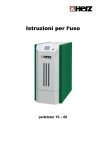
Download Betriebsanleitung FS Lambda Deutsch
Transcript
Assembly and installation instructions – Electrical documentation pelletstar 10 – 60 Introduction INTRODUCTION Dear Customer! Your heating equipment is powered using HERZ pelletstar boiler equipment and we are delighted to be able to welcome you into the large circle of satisfied operators of HERZ equipment. HERZ solar control is the result of many years of experience and further development. Please bear in mind that even a good product requires the right servicing and maintenance in order to be able to fulfil its functions. Please therefore read this documentation carefully – you will find it worthwhile. Please pay particular attention to the safety notes. It is a precondition of any warranty claim that all operating rules are maintained. Please contact your heating specialist or the HERZ factory customer service in the event of any faults. Yours sincerely from HERZ HERZ - Energietechnik Guarantee / warranty (general) HERZ boiler systems come with a 5-year warranty on the boiler body, storage tanks and HERZ solar collectors. We generally guarantee freedom from defects of mobile objects purchased for a period of 2 years, to a maximum of 6.000 hours of operation. For non-moving purchased items, the guarantee is generally for a period of 3 years to a maximum for 9.000 hours of operation. Parts subject to wear are excluded from the warranty/guarantee. Furthermore, claims under warranty will not be applicable if there is no return flow 1 temperature boost or it is not working properly, if commissioning is not carried out by specialist personnel authorised by HERZ, in the case of operation without a buffer storage tank with a heating load of less than 70% of the rated output (manually stoked boilers must always be operated with a sufficiently dimensioned 2 buffer storage tank), if hydraulic diagrams , not recommended by HERZ are used and if a non-prescribed 3 fuel , Wood pellets for non-industrial use after ENplus, Swisspellet, DINplus or ÖNORM M 7135 resp. pellets after EN14961-2; Wood chips after EN 14961-1/4 according to the following specification: Property class A1, A2, B1 respectively G30, G50 according to ÖNORM M7133 resp. log wood is used. As a precondition for the use of guarantees, annual maintenance by a HERZ authorised specialist applies. Guarantee work does not affect any extension of the general term of guarantee. A guarantee claim does not delay the due date of our accounts. We only offer a guarantee if all our accounts have been paid for the product delivered. The guarantee is fulfilled at our discretion via the repair of the purchased item or replacement of faulty parts, exchange or reduced price. The exchanged parts or goods must be sent back to us free of charge at our request. Wages and costs for installation and removal are to be paid for by the purchaser. This applies in the same way to all guaranteed services. The Supplier shall under no circumstances be liable to the Customer, for any direct, indirect or consequential costs incurred by the Customer for works carried out on HERZ equipment. This document is translated from the original (German language). Reprints or copies, even in extracts, only by approval of HERZ© – Energietechnik. We reserve the right to make technical alterations. Version 04/2014 1 Maintenance by the manufacturer Recommended hydraulic diagrams can be found in the installation manual while hydraulic balancing will be carried out by the heating contractor 3 Furthermore, the quality of the heating water must be in accordance with ÖNORM H5195 (current version) or VDI 2035 2 2 Montage- Installationsanleitung - E-Doku pelletstar Touch Englisch V1.81 Table of content TABLE OF CONTENT page page 1 Safety notes ................................... 5 1.1 Warning notes ...................................... 6 1.2 Installation ............................................ 6 1.3 Operation and maintenance ................ 7 1.3.1 1.3.2 1.3.3 General safety notes .............................. 7 Operation ................................................ 7 Maintenance ........................................... 7 2 Installation ..................................... 8 2.1 Starting up ............................................ 8 2.2 Important information for heating installers ................................................ 8 8.4.2 2.3 Safety installations............................... 9 8.5 2.4 Operating temperatures and prohibited temperatures ...................... 9 Flexible screw discharge – Item number A031000-080.......................... 30 8.6 Connection diagram transfer system32 8.7 Slide bevel ........................................... 33 9 Standard diagrams ...................... 34 10 Electrical documentation ............ 41 10.1 Safety regulations .............................. 41 10.2 General ................................................ 41 10.3 Plug system used ............................... 41 10.4 Heating control system HZS 555-S ... 42 10.5 Pin configuration HZS 555-S ............. 42 10.6 Cleaning of the Touch-Screens ........ 43 10.7 Operating part ..................................... 44 10.8 Safety temperature limiter (STL) – cut-off................................................... 50 7 Correct storage area ................... 20 8 Installation of the removal system21 8.1 Suction probe ..................................... 21 8.2 Layering and assembly of the pellet feed hose ............................................. 21 8.3 Vacuum discharge system (modular)22 8.4 Flexible screw discharge – item number A031000-000.......................... 25 8.4.1 Advice for the laying of the pellet feed hose ...................................................... 25 Installation............................................. 26 2.4.1 2.4.2 Boiler temperature .................................. 9 Back-flow temperature ........................... 9 3 Fuels............................................. 10 4 Technical information ................. 11 4.1 Choice of nominal heat capacity ...... 12 4.2 Hydraulic connection ......................... 12 4.3 Back-flow bypass ............................... 12 4.4 Thermal flow guarantee ..................... 12 4.5 Draught limiter and explosion flap ... 12 4.6 Flue gas system ................................. 12 5 Dimensions .................................. 13 6 Installation and deinstallation .... 15 6.1 Boiler insertion ................................... 18 10.9 Extension modules internal .............. 50 6.1.1 10.9.1 10.9.2 6.1.2 With the help of a crane eye resp. transport lug ......................................... 18 With hand pallet truck ........................... 18 6.2 Positioning .......................................... 18 6.2.1 6.2.2 Boiler without container ........................ 18 Boiler with container ............................. 19 6.3 Wiring .................................................. 19 6.4 Installation container handover snail20 Extension controller internal (HZS 532) 50 Heating circuit module internal (HZS 533)....................................................... 51 Hot water tank module internal (HZS 534)....................................................... 52 Buffer module internal (HZS 534) ......... 53 Solar module internal (HZS 535) .......... 54 Hydr. Compensator module internal (HZS534) .............................................. 56 Net pump / Zone valve internal (HZS534) .............................................. 56 10.9.3 10.9.4 10.9.5 10.9.6 10.9.7 Montage- Installationsanleitung - E-Doku pelletstar Touch Englisch V1.81 3 Table of content page 10.10 Extension modules external ............. 57 10.10.1 Heating circuit module external (HZS 543) ...................................................... 59 10.10.2 Buffer module external (HZS 544) ....... 61 10.10.3 Solar module external (HZS 545) ......... 62 10.10.4 Hot water tank module external (HZS 546) ...................................................... 64 10.10.5 Additional boiler module external (HZS 547) ...................................................... 65 10.10.6 Request module external (HZS 548) .... 66 10.10.7 Hydr. Compensator module external (HZS546) .............................................. 68 10.10.8 Net pump / Zone valve external (HZS546) .............................................. 68 11 Index............................................. 69 12 Notes ............................................ 70 4 Montage- Installationsanleitung - E-Doku pelletstar Touch Englisch V1.81 Safety notes 1 1 SAFETY NOTES Please read the operating instructions carefully prior to start-up and pay particular attention to the safety notes marked. Please consult these instructions for clarification. Ensure that you understand the directions in this manual and that you have sufficient information about the functioning of the firematic biomass furnace equipment. HERZ is at your disposal at all times for any questions. For safety reasons the operator of the equipment may not alter its construction or condition without the agreement of the manufacturer or its authorised representative. Ensure that there is sufficient fresh air supply to the boiler room. (Please take into account the current federal state regulations) The gas and liquid tightness of all connecting points is to be monitored before the equipment is started up. A portable fire extinguisher of the prescribed size must be placed in front of the boiler room. (Please take into account the current federal state regulations) When opening the combustion chamber doors take care that no flue gas and sparks are released. Never leave the combustion chamber door open. Toxic gases may escape. Never heat up the boiler with liquid fuels such as petrol or similar. Carry out maintenance work regularly (maintenance plan) or use our customer service. (Minimum TRVB maintenance intervals must be adhered to) For maintenance of the equipment or when opening the controls, the flow supply must be interrupted and the general applicable safety rules must be adhered to. No fuels should be stored outside the equipment in the boiler room Furthermore, items that are not required for the operation or maintenance of the equipment must not be stored in the boiler room. It is vital that the boiler is switched off when filling the fuel bunker using a pump vehicle. (Markings are on the lid of the filling nozzles). Non-compliance may allow combustible and toxic gases to enter the storeroom. The fuel bunker must be safeguarded against entry by unauthorised persons. Always cut off the power supply if you have to enter the fuel bunker. Always use low voltage bulbs to light the storeroom (these must be approved for this purpose by the manufacturer). The equipment may only be operated using designated fuels. Prior to onward transportation of ashes, these must be cooled down for a minimum of 96 hours in the storeroom. In case of any questions please contact us by telephone +43 3357 / 42840-840. The first start-up must be carried out by HERZ factory customer service or an authorised specialist. (Otherwise the guarantee becomes invalid). Before entering the pellets storeroom aerate for 30 minutes! The boiler conforms the regulation of the Swiss VKF and respectively the particular state regulations regarding fire prevention. The costumer is fully responsible for the compliance with those regulations. Montage- Installationsanleitung - E-Doku pelletstar Touch Englisch V1.81 5 1 1.1 Safety notes Fundamental security information Warning notes Means that injuries or damage of property may occur in case of inappropriate handling of the installation. Warning – hot surface Warning – potential injury to hands No access persons for Due to its functional electrical and mechanical character the installation, in case of inappropriate handling, operation and maintenance or in case of illicit intervention, the installations may cause severe injuries and damages of property. Therefore it is mandatory that planning and assembly of all installation, transport, operation and maintenance is carried out through qualified responsible field service personnel. unauthorized Compliance with other non-highlighted advice concerning transport, assembly, handling and maintenance or technical data (in user manuals, in product documentations and applied on the installation itself) is mandatory to avoid any problems that may lead directly or indirectly to severe injuries or damages of property. General notice Operating electrical systems must have the effect that certain electrical parts are live parts and therefore any contact could be dangerous. Only trained and qualified personnel may work at this installation. The personnel must have been familiar with this and all other manuals. Proper and safe use of the system needs appropriate transport, correct storage and appropriate operation and maintenance. Advice and details attached to the system have to be noted. This user manual contains due to clearness and due to the possible multitude not all detailed information and may not consider each possible case of operation or maintenance. In case of additional information requests or in case of specific problems that are not mentioned in the attached user manuals your specialist dealer or HERZ may provide further information. 1.2 People (including children) who are not in a position to use the equipment safely due to their physical, sensory or mental capacities or their inexperience or lack of knowledge should not use this equipment without supervision or instruction by a responsible person. Manufacturer documents for the devices and components being used the equipment are available from HERZ upon request. 6 Installation General security note Safe operation and safe maintenance of the system request that they are carried out by qualified personnel, considering the warning advice of this user manual and the details attached on the systems. Montage- Installationsanleitung - E-Doku pelletstar Touch Englisch V1.81 Safety notes 1.3 Operation and maintenance 1.3.1 General safety notes For safe operation and maintenance of the equipment, it is vital that actions are carried out appropriately by qualified staff, taking heed of the warning notes in this documentation and the notes on the equipment. 1 Where the minimum residual oxygen content of 5% in the flue gas is not reached, the fuel supply is stopped automatically and is only activated once again when the residual oxygen content is over 5%. (Display readout: MIN O2 [%] 5.0) The noise caused by the machinery during operation does not have any adverse effects upon the health of people. 1.3.3 Maintenance General safety notes The equipment may only be opened when “HEATING OFF” is indicated as there is otherwise a risk of deflagration. With unfavourable operating conditions temperatures of over 80°C may occur at parts of the casing. When opening the ash storage door during operation the fuel supply is cut off and the boiler goes into burnout phase. This then changes into the “HEATING OFF” mode of operation. 1.3.2 Operation General safety notes Coverings that prevent the moving of hot or rotating parts or which are required for the correct supply of air and effective functioning must not be opened during operation. Before commencing any work on the equipment, but particularly before opening coverings of parts under voltage, the equipment must be enabled according to the instructions. As well as the main electrical circuit, any additional or auxiliary circuits should be noted. The usual safety rules according to ÖNORM are: Switch off all poles on all sides Ensure that it is not switched on again Check that there is no voltage Earth and short-circuit Cover neighbouring voltage-carrying parts and limit danger spots Any faults or unusual operating conditions such as the emission of smoke or the appearance of flames mean that the equipment must be immediately switched off using EMERGENCY OFF. HERZ must then be notified of this straight away. Where the main switch on the heating room door is activated or if the power supply fails, the equipment immediately goes out of operation. The residual installation of fuel burns independently without toxic gases being given off, provided that the naturally occurring chimney draw is sufficiently high. The chimney must therefore be dimensioned and designed according to EN 13384 and DIN4705. It is obligatory to check the complete installation for serviceability and to ensure a safe operating at each restart. Montage- Installationsanleitung - E-Doku pelletstar Touch Englisch V1.81 These above mentioned measures many only be cancelled if the equipment is completely installed and the commissioning completed. For overhaul work in the combustion chamber, ash chamber, on flue gas-carrying parts, emptying of the ash store, etc., the use of personal dust protection masks and gloves is required! For overhaul work in the storage room, low voltage bulbs must be used. The design of electrical equipment in the storeroom must conform to ÖNM7137. 7 2 Installation In order to prevent any commissioning errors due to incorrect maintenance, it is recommended that regular maintenance servicing be carried out by authorised staff or the HERZ factory customer service. Spare parts may only be obtained direct from the manufacturer or sales partner. No health risks will be caused to the customer from noise arising from the machinery. Details of any residual risks can be requested from the residual risk analysis from HERZ as required. 2 INSTALLATION 2.1 Starting up The first start-up must be carried out by HERZ factory customer service or an authorised specialist. An analogue temperature display is also installed ex-factory (also with submerged sensor). This should be tested weekly for correct functioning. The hydraulic balancing of the equipment (pipe installation) must be carried out by a licensed (authorised) specialist company (installer). The specialist company is obliged to: Install a correctly designed membraned expansion vessel Draft documentation for all the equipment (according to ÖNORM EN 12170), which must be kept in the boiler room. All recognised regulations, instructions and standards are to be applied by the specialist heating company. Heating water: Besides this the low pressure in the flue pipe connecting piece of the boiler has been measured after the combustion with the designated solid fuels at least one hour during the operation and an advance flow temperature of 70 - 85°C has been achieved. With regard to the quality of the heating water, take into account ÖNORM H 5195, for Germany – EN 12828 part 1, VDI 2034 (prevention of damage through corrosion and calcification in closed hot water heating systems with operating temperatures up to 100°C). It can thereby be determined whether feed pressure for the correct operation of the boiler (formerly described as draw requirement“) has set itself. If the existing chimney has not been measured correctly or if the calculated chimney values have not been met (inappropriate connection, entry of secondary air, connection piece too long, etc.) it will not be possible to operate the boiler correctly. Requirements e.g.: During start-up and handover to the operator, the functioning of all control and safety equipment must also be monitored and the operation and maintenance of the boiler and equipment must be explained to the operator in detail. 2.2 Chloride maximum 30mg/l pH-value 8 – 8,5 Oxygen maximum 0,1 mg/l The heating equipment must be filled by the installer according to the valid instructions and technical guidelines and with sufficient frost protection. When using frost protection parameters must be adhered to: At least 25% and maximum 50% proportion of ethylene or propylene-based frost protection agents, depending on the temperature level It is vital to take note of manufacturer details! He has received and familiarised himself with the operating instructions and any other documents, etc. Mix well before filling and do not mix any different frost protection agents (mark on the equipment!) Do not add any water to ready-mixed products! He is therefore sufficiently familiar with the equipment. Check equipment once a year for proportion of frost protection, pH value 7.5 - 9.5, corrosion protection and visual water quality. He has been sufficiently instructed on the correct operation and maintenance of the equipment. Note: The boiler return flow sensor is to be operated as a submerged sensor. 8 following Important information for heating installers The operator must confirm in writing that: the Montage- Installationsanleitung - E-Doku pelletstar Touch Englisch V1.81 Installation If the installation is NOT equipped with an antifreezing agent, freezing is possible in cases of a lasting electrical power cut (e.g. 2 days). To avoid that HERZ recommends an emergency generator that provides enough power for the boiler, the filter system (if existing) and the room discharge system. 2.3 Safety installations These must be dimensioned according to the ÖN B8133. and installed The safety valve in the boiler circuit is used as a final safety instance against malfunction of the system. Safety temperature limiter STL If the boiler temperature exceeds 95°C the system must be shut down for safety. The STL will lock in this case. Possible causes can be: 2.4 Operating temperatures and prohibited temperatures 2.4.1 Boiler temperature The HERZ pelletstar boiler is operated between 65 and 90°C boiler temperature in operation. Below 55°C back-flow temperature, a part of the flue gas is condensed on the inside of the boiler. To avoid condensation the operating temperature (of 65 to 90°C) must achieve this temperature as soon as possible at the boiler start. The back-flow temperature can also be below this value by correct boiler operating temperature. This condition must be avoided by a functioning backflow bypass 60°C. Caution! For corrosion damage caused by incorrect operating temperatures all guarantee and warranty decayed. 2.4.2 The power decrease of the boiler was abruptly interrupted. This may occur by switching off a pump or by a sudden closing of the heating circuit mixer. The consumer pumps are controlled by the HERZ control. The so-called over temperature dissipation is automatically activated by the HERZ control. Thereby higher boiler temperatures are avoided. The boiler is dimensioned too large The fuel level is set too high Power failure etc. 2 Back-flow temperature The back-flow temperature is always lower than the boiler temperature. The back-flow temperature must rise after the start as soon as possible on or above 60 °C. The hold up of the back-flow temperature and boiler temperature is realized by the back-flow bypass. At this the flow water is admixed with a pump and an appropriate valve to the back-flow. The heat energy of the boiler can be utilized only from that moment at which the back-flow temperature has exceeded 60°C. First, the error cause must be found and fixed, only then the STL will be unlocked. For unlocking the boiler temperature must be below about 75°C. Only then the problem can be acknowledged. For this purpose, the cover of the STL is screwed off. The STL can be unlocked by a light pressure with a sharp object. After unscrewing the cover, the fault acknowledgement must be performed at the switch box. The STL is located below the operator terminal. Montage- Installationsanleitung - E-Doku pelletstar Touch Englisch V1.81 9 3 3 Fuels FUELS Wood pellets for non-industrial use after ENplus, Swisspellet, DINplus or ÖNORM M 7135 resp. pellets after EN14961-2 according to following specifications: Property class A1 The maximum permissible fines content in the fuel store must not exceed 8% of the fuel volume stored (determined using a perforated screen with holes 5 mm in diameter)! Fines content at the time of loading: <1,0 m% Calorific value in as-delivered condition > 4,6 kWh/kg Bulk density BD in as-delivered condition > 600 kg/m³ Mechanical Strength DU, EN 15210-1 in asdelivered condition, m-%: DU97,5 ≥ 97,5 Diameter 6mm The nominal power and the emission values can be guaranteed up to a maximum water content of 25 % and a minimum calorific value of 3,5 kWh/kg of the permissible fuel. From a water content of about 25% and a calorific value < 3,5kWh/kg a reduced output is expected. Foreign bodies such as stones or metal particles should be prevented from entering the system! Sand and soil lead to more ash and slagging. According to the fuel there may be a formation of slag, which may need to be removed by hand. In the case of non-compliance, any warranty or guarantee will be rendered null and void. The burning of unsuitable fuels could lead to uncontrolled combustion. Operational faults and consequential damage are likely to occur. Is a different fuel on the order named and explicit on the order confirmation noted, the system can also be operated with this fuel. Note: The system is set to the agreed fuel at the commissioning. This setting (fan speed settings, fuel settings, flow/backflow fan, cycle time, and so on) should not be changed by constant fuel quality. 10 Montage- Installationsanleitung - E-Doku pelletstar Touch Englisch V1.81 Technical information 4 4 TECHNICAL INFORMATION Technical Data Nominal heat capacity [kW] Permissible flow temperature [°C] Permissible operational excess pressure [bar] Weight of boiler [kg] Water content [ltr] Volume of suction hopper [ltr / kg] Volume of hopper [ltr / kg] (Filling by hand) 10 20 30 45 60 4,8 – 16,0 95 6,2 – 21,0 95 6,2 – 30,0 95 10,1 – 45,0 95 10,1 – 60,0 95 3 3 3 3 3 261 55 86 / 56 310 78 86 / 56 310 78 86 / 56 518 178 109 / 71 518 178 109 / 71 165 / 107 165 / 107 165 / 107 195 / 137 195 / 137 min: 0,05 max: 0,10 Delivery pressure [mbar] Exhaust gas data: Exhaust gas temperature at nominal load [°C] Exhaust gas temperature at part load [°C] Mass flow flue gas at nominal load [g/s] CO2 – content at nominal load [Vol. -%] 130 120 150 110 130 80 80 80 80 80 7,9 14,0 19,0 29,0 36,0 13,6 11,7 12,0 12,3 13,4 45 60 Electrical connection: Electr. connection [V, Hz, A] / Delivery rate [kW] Electrical power consumption Standby [W] Filling (Suction turbine) [W] Plug-in [W] BBD [W] Flexible discharge [W] Heat exchanger cleaning [W] Grate cleaning [W] ID fan [W] Ignition process [W] At 100% capacity / lowest capacity [W] 230, 50, 16 / 2,0 10 20 17,5 1544 29 7 103 57 50 61 563 94 / 51 Montage- Installationsanleitung - E-Doku pelletstar Touch Englisch V1.81 30 16,1 1522 106 7 95 69 73 88 782 160 / 72 226 / 72 11 4 Technical information 4.1 Boiler and chimney must fit together. EN 13384 can be used to help with calculation. Choice of nominal heat capacity When choosing the boiler size, it should be noted that under heating equipment legislation, the nominal heat capacity according to the heat requirement stated in DIN 4701 and ONORM M 7500 (Swisspellet and DIN plus for Switzerland) should not be exceeded. When using frost protection the following parameters must be adhered to: At least 25% and maximum 50% proportion of ethylene or propylene-based frost protection depending on the temperature level 4.2 Hydraulic connection It is vital to take note of manufacturer details Boilers for solid fuels are not integrated into open equipment according to DIN 4751-1, but according to the installation examples into closed equipment, DIN 4751-2. Mix well before filling and do not mix any different frost protection agents (mark on the equipment) Do not add any water to ready-mixed products Check equipment once a year for proportion of frost protection, pH value 7.5-9.5, corrosion protection and visual water quality. Only regulated heating circuits with a mixer should be connected. 4.3 Back-flow bypass Reverse flow elevation is required. It must be ensured that the reverse flow temperature does not fall below 60°C. Attention: In case of corrosion damage due to low reverse temperature, guarantee and warranty claims become invalid. 4.4 Thermal flow guarantee No thermal process protection is required for types PS 10, 20 or 30. For pelletstar types 45-60 a safety heat exchanger must be installed in the boiler, to which thermal process protection must be connected. 4.5 Draught limiter and explosion flap Combustion air feed The combustion air feed should not contain impurities such as: Halogen hydrocarbons (sprays, solvents and cleaning fluid) Large attacks of dust High humidity content. There should be adequate ventilation (approximately 150 x 150mm). (For Switzerland according to VKF kWx10.3 2 2 cm with a minimum of 150 cm ). Otherwise applies: 5 cm² per kW boiler output, nevertheless at least 400 cm². Countryregulations must be kept. colours, The installation of a draught limiter is required and the draught requirement is between 5 and 10Pa. According to TRVB H 118 an explosion flap must be installed in the chimney (HERZ recommendation). 4.6 Flue gas system Connect the flue tube below an angle of 45°, steadily rising and thermally insulated to the chimney. It is recommended to mount the draw controller with explosion flap into the chimney (between flue pipe and cleaning door). If the draw controller was installed into the flue pipe, it would result in unwanted dust. Every flue pipe bow increases the flow resistance and can cause flow noises which are rectified by the chimney. This can lead to noise pollution. For this reason flue pipe bows should be avoided. 12 Montage- Installationsanleitung - E-Doku pelletstar Touch Englisch V1.81 Dimensions 5 5 DIMENSIONS pelletstar – for flexible screw discharge pelletstar – for suction discharge with interim container Connections Boiler Flow (Internal screw thread) 1 [inch] Return flow (Internal screw 2 thread) [inch] 3 Filling/depletion [inch] Safety heat exchanger input 4a (Internal screw thread) [inch] Safety heat exchanger output 4b (Internal screw thread) [inch] 5 Suction turbine return pipe 6 Suctiontube-connection 10 20 30 45 60 1 1 1 6/4 6/4 1 1 1 6/4 6/4 ½ ½ ½ ½ ½ – – – ½ ½ – – – ½ ½ Ø a 45 Ø a 60 Ø a 45 Ø a 60 Ø a 45 Ø a 60 Ø a 45 Ø a 60 Ø a 45 Ø a 60 Montage- Installationsanleitung - E-Doku pelletstar Touch Englisch V1.81 13 5 Dimensions Dimensions A1 A2 A3 A4 B1 C1 C2 C3 C8 D1 E1 E2 E3 E3* E4 Length overall Length boiler plus distance to BSDD centre line Length Boiler Length boiler plus distance to flue pipe centre line Width Height Height to flue pipe top edge Height to BSD top edge Minimum ceiling height Diameter flue pipe Minimal gap front Minimal gap rear Minimal gap left (without hopper) Minimal gap left (with hopper) Minimal gap right Inserting dimensions [mm] Length Width Height Inserting dimensions by hopper execution [mm] Length Width Height 14 10 20 30 45 60 1400 1400 1400 1620 1620 1235 1235 1235 1455 1455 900 980 980 1140 1140 1065 1140 1140 1290 1290 590 1130 925 390 1500 130 750 500 590 1230 1025 390 1600 130 750 500 590 1230 1025 390 1600 130 750 500 750 1480 1305 505 2100 150 750 600 750 1480 1305 505 2100 150 750 600 750 750 750 750 750 500 500 500 500 500 150 150 150 150 150 10 865 590 1130 20 940 590 1230 30 940 590 1230 45 1140 750 1480 60 1140 750 1480 10 20 30 45 60 940 650 1395 940 650 1395 940 650 1395 1140 890 1915 1140 890 1915 Montage- Installationsanleitung - E-Doku pelletstar Touch Englisch V1.81 Installation and deinstallation 6 6 INSTALLATION AND DEINSTALLATION Boiler as delivered The boiler is screwed on the pallet, the ash door is located on the boiler, the ash door must be attached. Then use an Allen key and install the upper door screw (preinstalled at the ash door). Door removed Hook in the fuse all the way to the stop Installation of the door stopper Place the door stopper in the slot on the pellet boiler. Screw the free end of the door stopper on the ash pan door so that the door stopper is movable. After this, the lower door screw can be installed. Montage- Installationsanleitung - E-Doku pelletstar Touch Englisch V1.81 15 6 Installation and deinstallation Deinstallation of the upper covering casing The screw has been loosened, the covering casing can now be removed by pressing backwards. Disengage the screw Remove the left front covering casing: The covering casing has to be removed by pulling movement (arrow) on the casing. The top cover must already be dismantled! Cover is removed by pulling movement Cover isn’t fixed with screws Remove the left back door panel: To dismantle the door panel, the front wall of the boiler must be dismantled before. For this the screws (see the lower picture) must be loosened. Upper back wall casing is detached, now the screws of the covering can be loosened. 16 Covering can be detached. Montage- Installationsanleitung - E-Doku pelletstar Touch Englisch V1.81 Installation and deinstallation 6 Open the front wall The front wall casing is a door. The casing is mounted on the right and swings to the right. Remove the right door panel To dismantle these, the front wall of the boiler must be dismantled before. For this the screws which are marked in the picture below must be loosened. Loosen the screw which is marked in the picture. Side panels can be removed. Ash ark Step 1: Open the ash door; then push the first ash ark with the delivered ash hook in the opening Step 2: The second ash ark can be pushed in by hand. Montage- Installationsanleitung - E-Doku pelletstar Touch Englisch V1.81 Step 3: Fix the second ash ark with the mounted lever. 17 6 Installation and deinstallation 6.1 Boiler insertion 6.1.1 With the help of a crane eye resp. transport lug 6.1.2 With hand pallet truck Palett: By insertion of the boiler with a hand pallet truck it is necessary that by lowering of the boiler the two fixing screws (front left and right back on the boiler) must be removed from the pallet. 6.2 Positioning 6.2.1 Boiler without container Positioning of the boiler according to the plan! Sound insulation is recommended. Front: floor space front at least 750mm Back: Positioning from behind according to the plan resp. at least 750mm related to the back wall covering Left: floor space left at least 750mm Right: Positioning of the right side according to the plan resp. at least 150mm related to the covering Attention: flexible pipe length must be at least 1000mm 18 Montage- Installationsanleitung - E-Doku pelletstar Touch Englisch V1.81 Installation and deinstallation 6.2.2 Boiler with container pelletstar 10-30: The distance between container and boiler is 3mm. 6.3 6 pelletstar 45-60: The distance between container and boiler is 3mm. Wiring This cable is connected by the control. The above circled openings are cable channels in which the cables for heating circuit connections and additional boards can be retracted. Montage- Installationsanleitung - E-Doku pelletstar Touch Englisch V1.81 19 7 6.4 Correct storage area Installation container handover snail The screw-conveyor is connected with the delivered terminals on the container handover snail! The height can be adjusted and the container can be justified with the foot screws. 7 CORRECT STORAGE AREA (1) Injection neck (2) Fire protection door (3) Wooden post (4) Baffle (5) Feeder screw or suction probe The most important points are: The storage room should have an outer wall, be small and square, with the blow-in supports on the face. It should contain the annual requirements. The walls must be solidly bricked and thick (brick walls plastered both sides). Fire protection category F90 (Switzerland EI 60), fire protection doors or hatches to T30 (Switzerland El 30). The outward opening door should be supported by wooden posts. A rubber mat (or baffle) should be placed opposite the blow-in supports to protect the wall. The storage room must be dry. In case of any doubts, ask your pellet supplier or contact your heating manufacturer. Openings of any kind are to be avoided, pipes to be closed off, and old electrical installations clamped off and filled in. The room must be (dust) –tight. Tip: before blowing in, close off the key hole with sticky tape. Electrical installations (lights) are prohibited except those that are protected. Both supports are to be bricked in with a 1m gap (do not insulate). Should the gap be smaller then use a support 50cm longer. Storage must conform to ÖNORM 7137. Transportation and storage logistics must conform to ÖNORM M 7136. 20 Montage- Installationsanleitung - E-Doku pelletstar Touch Englisch V1.81 Installation of the removal system 8 INSTALLATION OF THE REMOVAL SYSTEM 8.1 Suction probe 8 65 mm Attention: Assembly of the probe holder has to be carried out so that the pipe is at least 65mm above the floor of the pellet storeroom. Important: When connecting the pellet feed hose to the probe you must bend the earth wire outwards in order to achieve the earthing of the feed hose with the probe. 8.2 Layering and assembly of the pellet feed hose When laying the pellet feed hose, take care that the maximum feed height of 1,5 metres is not exceeded. Max. 1,5m vertical After vertical hose feeding, laying must always be carried out horizontally around 300mm. You can the overcome several metres difference in height. Ca. 300mm horizontally The pellet feed hose is fixed to the wall or floor with hose clips about every 50cm. The maximum length of the suction hose is: 20 metres The maximum negotiable height difference is: 5 metres The installation radius must not be lower than 0,3 metres. Montage- Installationsanleitung - E-Doku pelletstar Touch Englisch V1.81 21 8 8.3 Installation of the removal system Vacuum discharge system (modular) Place the screw according to layout/submission plan from HERZ Mark the holes to drilled on the floor Remove the screw again Drill the holes (for dowels) using a drill. Place the dowels supplied in the drill holes Replace the screw Use and tighten the adjusting screws supplied Installing the noise insulation Screwing together the discharge screw Install the noise insulation on the support struts. First the two parts of the discharge screw are put together. Then these are screwed together by using an M6 countersunk-head screw, until all extension pieces are screwed together. Putting together the discharge screw and the end support strut After the discharge screw is assembled a sleeve is put on the end of the screw. This is screwed on using an M6 countersunk-head screw. When the sleeve is mounted on the screw this is simply mounted on the end support strut so that the discharge screw stands out approximately 5-10mm from the bearing. 22 Montage- Installationsanleitung - E-Doku pelletstar Touch Englisch V1.81 Installation of the removal system 8 Protecting the discharge screw from twisting Applying decompression to the discharge screw and interim support struts By using both Allen screws the discharge screw is saved against twisting. A greasing nipple is provided for greasing the bearing. The bearing should be greased every 2-4 weeks by using the greasing nipple. Now apply the decompression near to the end support strut of the discharge screw. Then give the interim support struts over the decompression and raise the decompression so that the holes of the decompression and the holes of the interim- and end support struts are over each other. Screwing together the decompressor and the end support strut Screwing together the decompressor and the interim support strut After raising, the decompressor is screwed together with the end support strut. Use an M8x25 Allen key. Before screwing on the M8 nuts place in the insert. After this the second decompressor (extension module) is lifted on to the interim support strut, so that both decompressors can be screwed together with the interim support strut, provided that all decompressors are screwed together. Then use the M8x25 Allen key, M8 inserts and M8 nuts for this. Screwing together the decompressor and the piece that fits into the wall After screwing together the decompressors, the last decompressor is simply screwed on to the piece that goes through the wall. Use the M8x25 Allen screws, M8 inserts and M8 nuts for this. Montage- Installationsanleitung - E-Doku pelletstar Touch Englisch V1.81 23 8 Installation of the removal system Assembling the motor and the discharge screw The motor is put together with the stub of the feather key of the discharge screws, so that the feather key goes into the nut. Afterwards the screw and the motor are screwed together using 4 M10x70 Allen screws. The motor should only be installed on the discharge screw as is shown in the image above. The discharge screw is safeguarded against slippage by using a pulley and a M8 Allen screw. Attachment of the capacity Clamping of the return air hose Clamping the transportation sensor to the discharge screw: hose to the discharge screw When the installation of the motor is completed the capacity sensor is simply placed in the sleeve provided. 24 First determine the required hose length between the boiler and discharge. Then clamp the hose onto the right support, seen from the front. First place the required length between the boiler discharge. Then clamp the onto the left support, seen the front. hose and hose from Montage- Installationsanleitung - E-Doku pelletstar Touch Englisch V1.81 Installation of the removal system 8.4 8 Flexible screw discharge – item number A031000-000 Functioning of the flexible screw discharge – The flexible screw discharge works as follows: In the storage room there is a fixed decompression in lengths of 2 to 4m open areas to remove pellets. Among them is the flexible screw which is to be fitted in the area of the open part using a conveyor. Outside the storage room the screw is led into a wear-resistant hose (up to a maximum of 5m) up to the release head which is placed on the burn-back protection equipment, where the discharge motor is located. Pellet storeroom The slide bevel of 45° should be set up on-site! Detail of hose connection Pressure discharge Hollow screw Hose Hollow screw 8.4.1 Support Support strut strut Advice for the laying of the pellet feed hose Note: Sagging of the hose and choosing small radiuses (Rmin = 1250mm) have to be avoided! Montage- Installationsanleitung - E-Doku pelletstar Touch Englisch V1.81 25 8 8.4.2 Installation of the removal system Installation Install the noise insulation on the support struts. Screw on the end piece with the decompressor by using the four M8 screws, inserts and nuts provided. Flange the decompressor and the support strut by using the four M8 screws, inserts and nuts provided. Flange the decompressor and the piece that goes through the wall by using the four M8 screws, inserts and nuts provided. Connect the dosing bolt and screw it in by using the M6 countersunkhead screw. Place the decompressor on the head and place the screwed dosing bolt in it, so that the end piece is lying on the end piece of the decompressor. Positioning the decompressor and the dosing bolt according to the layout plan. Before this check the noise insulation on the support struts. Place the piece that goes through the wall (pipe) between the first two flanges of the opening. Connect the end stump of the dosing bolt with the covering and screw it with the countersunk head M6 screw. 26 Montage- Installationsanleitung - E-Doku pelletstar Touch Englisch V1.81 Installation of the removal system 8 Soundproof the decompression in the area of the gap. (example: rock wool at least 250mm compressed with melting point > 1000°C) The decompression must be pushed no further than the first flange (strut) in to the wall of the storage room. Drill a hole in the floor where Diam.=12 and D=70 for the strut. Nylon 12x60 dowel and hexagonal Put in the 10x70 set screw. Fix the set screw Re-adjust the decompression and fix it at the end – after that the rest of the struts are fixed. Take the release head and motor from the BBD by loosening the fixing clips. Take the discharge motor with motor flange from the release head by opening the 4 piece M8x16 hexagonal screws. Check that the M8x10 grub screw of the screw coil intake is tightened. Montage- Installationsanleitung - E-Doku pelletstar Touch Englisch V1.81 27 8 Installation of the removal system Arrange the release head centred on the BBD and clamp again – the connection pipe should face the decompression direction (see installation plan). Measure the hose length (L) between the connection pipes from the release head and decompression. Attention: Note the bend radius for laying the hose. At the release head add 150mm hose length for assembly. At the decompression add 150mm hose length for assembly. Sever the metal-spiral reinforced hose using a hacksaw or angle grinder. At the place where it is cut, trim with a knife or file. Ltot=L+150+200 ! Push the 200mm plastic pipe (until the point where it resists) into the connection pipe of the decompression. Fasten the hose clip tightly to the end of the pipe. Push the 150mm release head over the hose (until it meets resistance). Tip: Greasing the hose makes this much easier. 28 Montage- Installationsanleitung - E-Doku pelletstar Touch Englisch V1.81 Installation of the removal system 8 Rmin = 1250mm Arrange the release head centred on the BBD and clamp once again. Fasten the hose clip tightly to the end of the pipe (so that the hose and the pipe are pressed together). Arrange the flexible hose horizontally with the same bend radius (Rmin=1250mm). Arrange the hose vertically with the same bend radius (Rmin=1250mm). Fasten the release head with the four screws, pulley and the flange clips. Push the flexible screw spiral into the release head. Push the screw spiral through the plastic hose. Push the screw spiral over the conveyor. Turn the screw spiral on the soldered screw spiral until it meets resistance. Push the screw with the conveyor to the end of the decompression. Rmin = 1250mm Montage- Installationsanleitung - E-Doku pelletstar Touch Englisch V1.81 29 8 Installation of the removal system Sever the spiral screw lengthways (flush with the motor flange) using an hacksaw or angle-grinder. Push the screw clamp inwards on the spiral at the release head with the screw. Turn the discharge motor with the Screw on, take on the coil until it meets resistance. Push the clamp over both coils. Tighten the clamp against loosening). Fix the motor with motor flange using the 4 nuts and screws. Tighten the screws!! Recondition the plug connections for the discharge and BBD. (protection Attention: The maximum length of the feeder hose must not exceed 5 metres. 8.5 30 Flexible screw discharge – Item number A031000-080 Montage- Installationsanleitung - E-Doku pelletstar Touch Englisch V1.81 Installation of the removal system 8 Installation of the flexible screw discharge: Revision cover Re-fix the discharge motor on the wall passage piece with the transfer system using the four screws. Secure the lower transfer system using the clip. Screw the screw flight into the bolt with the welded on screw. Unscrew the covering to check whether the screw is pushed right up to the stopping point. Push the screw flight into the lower transfer system Replace the covering Montage- Installationsanleitung - E-Doku pelletstar Touch Englisch V1.81 See flexible screw discharge – Item number A031000-000 31 8 Installation of the removal system 8.6 Connection diagram transfer system Operating part X9 L 1 N 2 PE 3 Settings of the time relay: Configuration: X43 +24V 1 2 Cycle: 15 sec Pause: 3 sec Beginning with pause A1 1 A2 3 Time relay TI 72 Signal Signal Pause Pause Pin 1 6 5 4 3 2 1 6 5 4 3 2 1 AS 2 Flexible screw to the boiler AS 1 Storage room Capacitor connect on motor Don´t connect capacitor parallel Position of the relay for the transfer system: Relay 32 Montage- Installationsanleitung - E-Doku pelletstar Touch Englisch V1.81 Installation of the removal system 8.7 8 Slide bevel Detail slide bevel PELLETS 3 650 kg/m min.50 Slide 45° Screw min. 250 max. 300 Substructure The slide bevel in the angle of about 45°C (with a smooth surface, ideal with laminate floor) is to be provided by the customer. Montage- Installationsanleitung - E-Doku pelletstar Touch Englisch V1.81 33 9 9 34 Standard diagrams STANDARD DIAGRAMS Montage- Installationsanleitung - E-Doku pelletstar Touch Englisch V1.81 Standard diagrams Montage- Installationsanleitung - E-Doku pelletstar Touch Englisch V1.81 9 35 9 36 Standard diagrams Montage- Installationsanleitung - E-Doku pelletstar Touch Englisch V1.81 Standard diagrams Montage- Installationsanleitung - E-Doku pelletstar Touch Englisch V1.81 9 37 9 38 Standard diagrams Montage- Installationsanleitung - E-Doku pelletstar Touch Englisch V1.81 Standard diagrams Montage- Installationsanleitung - E-Doku pelletstar Touch Englisch V1.81 9 39 9 40 Standard diagrams Montage- Installationsanleitung - E-Doku pelletstar Touch Englisch V1.81 Electrical documentation 10 ELECTRICAL DOCUMENTATION 10.1 Safety regulations 10 The equipment is state of the art and fulfils all required safety standards. It may only be used according to the technical information and the safety regulations which are listed below. When using the device you have to observe the essential legal and safety regulations for the specific application. A safe operation is no longer possible if the device has visible damage no longer works has been stored for long periods under unfavourable conditions If so, the device must be taken out of service and secured against inadvertent operation. 10.2 General All inputs / outputs and supplies are plugged in direct to the operating part and extension module. It is ensured that it is not possible to change between 230V AC, 400V AC and low voltage, which may lead to electronic defects of connected equipment as well as probes. However, it is possible for 230V AC connections (pumps, mixers, etc.) to be swapped around. This cannot be avoided due to the number of connections. However, swapping of the low voltage inputs / outputs is possible, and this will not cause electronic or probe defects. 10.3 Plug system used Multipoint connector on the circuit board Grid: 5,08 mm (230 VAC) Grid: 7,62 mm (400 VAC) Multipoint connector on the circuit board Grid: 3,5 mm Screw clamp Grid: 5,08 mm (230 VAC) Screw clamp Grid: 7,62 mm (400 VAC) Grid: 3,5 mm Montage- Installationsanleitung - E-Doku pelletstar Touch Englisch V1.81 41 10 Electrical documentation 10.4 Heating control system HZS 555-S The HCS 555-S is an intelligent terminal for programming and visualization of automated processes. The diagnostic process and the operation and monitoring of automated processes are simplified by this installation terminal. Via CAN-Bus it is connected with the active component. A touch screen is used to enter data and process parameters. The output is displayed on a 5.7 "VGA TFT colour display. The LSE mask editor can create graphics on a PC and can save on the installation terminal. The available interfaces can be used for transferring process information or for configuration of the installation terminal. A micro SD card is storage medium for the operating system, application and application data. 10.5 Pin configuration HZS 555-S X1 - Supply Pin 1 2 3 4 Function n.c. +24 V DC GND GND Pin 1 2 3 4 Function CAN A (for external modules) CAN B (for external modules) CAN A (internal pre-wired) CAN B (internal pre-wired) The termination of the CAN bus is internal to the electronics! 5 GND The total CAN bus cable length may be max. 200 metres. 6 - Pin 1 2 3 4 5 6 7 8 9 Function DCD RX TX DTR GND DSR RTS CTS RI X2 - CAN X3 – RS232 (Front view) 42 Montage- Installationsanleitung - E-Doku pelletstar Touch Englisch V1.81 Electrical documentation 10 X4 – Ethernet Pin 1 2 3 4 5 6 7 8 Function TX + TX RX + n.c. n.c. RX n.c. n.c. Pin 1 2 3 4 5 Function +5V DD+ GND X5 – Mini USB Typ B (V1.1) (not used) X6 – USB 2.0 (Typ A, Full Speed, 12 Mbit/s) Pin 1 2 3 4 Function +5V_USB DD+ GND It should be noted that many USB devices on the market do not adhere the relevant EMC requirements of the industrial environment. When such devices are connected, it may cause a malfunction. Connectors to be used: CAN-Bus: 6-pole Weidmüller-Connector B2L3, 5/6 USB: 4-pole Typ A (Downstream Connector) Ethernet: 8-pole RJ45 Supply: 4-pole Phönix-Connector witch terminal technique MC1, 5/4-ST -3,5 4-pole Phönix-Stecker with spring balancer terminal F K-MCP1, 5/4-ST -3,5 10.6 Cleaning of the Touch-Screens ATTENTION! Before cleaning the touch screen, turn off the terminal so that you cannot cause functions or commands by touching the touch screen. The touch screen of the terminal may only be cleaned with a damp, soft cloth. When moistening the cloth use screen cleaner, for example: anti-static foam cleaner, water with detergent or alcohol. First spray the cleaning solution on the cloth, not directly on the terminal. It is to be avoided, that the cleaning solution for example through ventilation slots on the casing of the terminal can enter the electronics. Do not use corrosive cleaning solutions, chemicals abrasives and hard objects which can scratch and damage the touch screen. If the terminal is polluted with toxic, caustic chemicals then clean the terminal carefully to prevent chemical burns! To ensure optimal operation of the terminal, clean the touch screen in regular intervals. To keep the life of the touch screen as long as possible, an operation with the finger is recommended. Montage- Installationsanleitung - E-Doku pelletstar Touch Englisch V1.81 43 10 10.7 Electrical documentation Operating part X1 – 230 V AC-Mains supply line – Phönix RM 5,08 Pin 1 2 3 Signal L N PE Function Phase Neutral conductor Earthed conductor X2 – 230 V AC-Output for extension module not over STL – Phönix RM 5,08 Pin 1 2 3 Signal L N PE Function Phase (over 10A fuse) Neutral conductor Earthed conductor X3 – 230 V AC- Output for extension module over STL – Phönix RM 5,08 Pin 1 2 3 Signal L N PE Function Phase switched over STL (over 10A fuse) Neutral conductor Earthed conductor X4 – STL Safety contact (230 V AC) – Phönix RM 5,08 Pin 1 2 44 Signal L L-STB Function Phase Phase L- switched over STL Montage- Installationsanleitung - E-Doku pelletstar Touch Englisch V1.81 Electrical documentation 10 X5 – 230 V AC-Relay output: Ignition heating and ignition ventilator – Phönix RM 5,08 (DO01 and DO05) Pin Signal Function 1 LHeating Relay output heating – switched over STL 2 LVentilator Relay output ventilator – switched over STL 3 N Neutral conductor 4 PE Earthed conductor X6 – 230 V AC-Relay output: Suction turbine – Phönix RM 5,08 (DO02) * by flexible discharge system: Pellet stirrer – Phönix RM 5,08 (DO02) Pin 1 2 3 Signal L N PE Function Relay output – switched over STL Neutral conductor Earthed conductor X7 – 230 V AC-Relay output: Grid cleaning – Phönix RM 5,08 (DO03) Pin 1 2 3 Signal L N PE Function Relay output – switched over STL Neutral conductor Earthed conductor X8 – 230 V AC-Relay output: Heat exchanger cleaning – Phönix RM 5,08 (DO04) Pin 1 2 3 Signal L N PE Function Relay output – switched over STL Neutral conductor Earthed conductor X9 – 230 V AC-Relay output: Motor discharge screw – Phönix RM 5,08 (DO06) Pin 1 2 3 Signal L N PE Function Relay output – switched over STL Neutral conductor Earthed conductor X10 – 230 V AC-Relay output: BFP open – Phönix RM 5,08 (DO07) Pin 1 2 3 Signal L N PE Function Relay output – switched over STL Neutral conductor Earthed conductor X11 – 230 V AC-Relay output: Container screw – Phönix RM 5,08 (DO08) Pin 1 2 3 Signal L N PE Function Relay output – switched over STL Neutral conductor Earthed conductor X12 – 230 V AC-Relay output – Phönix RM 5,08 (DO09) – not used Pin 1 2 3 Signal L N PE Function Relay output – switched over STL Neutral conductor Earthed conductor X13 – 230 V AC-Relay output – Phönix RM 5,08 (DO10) – not used Pin 1 2 3 Signal L N PE Function Relay output – switched over STL Neutral conductor Earthed conductor Montage- Installationsanleitung - E-Doku pelletstar Touch Englisch V1.81 45 10 Electrical documentation X15 – 230 V AC-Phase angle control: ID fan – Phönix RM 5,08 (Phase2) Pin 1 2 3 Signal L N PE Function Output phase angle control. – switched over STL Neutral conductor Earthed conductor X16 – Triac output: Stoker screw – Phönix RM 5,08 Pin 1 2 3 Signal L N PE Function Triac output – switched over STL Neutral conductor Earthed conductor X17 – 230 V AC-Relay output (3A / 3 Pole): Back flow pump – Phönix RM 5,08 (DO11) Pin Signal Function 1 L Relay output – not switched over STL 2 N Neutral conductor 3 PE Earthed conductor X18 – 230 V AC-Relay output (3A / 4 Pole): Reverse mixer on and reverse mixer off – Phönix RM 5,08 (DO12 and DO13) Pin Signal Function 1 LON Relay output RM on – not switched over STL 2 LOFF Relay output RM off – not switched over STL 3 N Neutral conductor 4 PE Earthed conductor X20 – Relay output (230V AC or +24V DC / 3A / 3 Pole) with potential-free contact: Sum annoyance – Phönix RM 5,08 (DO15) Pin Signal Function 1 NC Normally Closed 2 C Common 3 NO Normally Open X21 – Relay output (230V AC or +24V DC / 3A / 3 Pole) with potential-free contact: Temperature monitoring fuel storage – Phönix RM 5,08 (DO16) Pin Signal Function 1 NC Normally Closed 2 C Common 3 NO Normally Open X22 – Relay output (230V AC or +24V DC / 3A / 3 Pole) with potential-free contact: Operating alarm unit – Phönix RM 5,08 (DO17) Pin Signal Function 1 NC Normally Closed 2 C Common 3 NO Normally Open X23 – Relay output with potential-free contact: Release stoker screw – Phönix RM 5,08 (DO18) Pin 1 2 Signal NC C Function Normally Closed Common 3 NO Normally Open X25 – Temperature input Back-flow temperature – Phönix RM 3,5 (AI2) Pin 1 2 46 Signal AI2 AGND Function Analog input AI2 PT1000 (-10 … +120°C) AGND Montage- Installationsanleitung - E-Doku pelletstar Touch Englisch V1.81 Electrical documentation 10 X26 – Temperature input Boiler temperature – Phönix RM 3,5 (AI3) Pin 1 2 Signal AI3 AGND Function Analog input AI3 PT1000 (-10 … +120°C) AGND X27 – Temperature input Stoker screw – Phönix RM 3,5 (AI4) Pin 1 2 Signal AI4 AGND Function Analog input AI4 PT1000 (-10 … +200°C) AGND X30 – Temperature input Flue gas temperature – Phönix RM 3,5 (AI7) Pin 1 2 Signal AI7 AGND Function Analog input AI7 PT1000 (0 … +600°C) AGND X31 – Temperature input Clamping unit temperature – KTY sensor is fixed on the circuit board!! X32 – Temperature input Combustion room temperature – Phönix RM 3,5 (AI9) Pin Signal 1 AI9+ 2 AI9- Function Analog input AI9+ Combustion room temperature NiCr-Ni (K-Typ) (0 … +1200°C) Analog input AI9- X34 – Lambda sensor LSM11 – Phönix RM 3,5 (AI11) Pin Signal Function 1 AI11+ Analog input AI11 Lambda sensor signal input pos. 2 AI11Analog input. AI11 Lambda sensor signal input neg. 3 12 V AC1 Sensor heating 12 V AC 4 12 V AC2 Sensor heating 12 V AC X36 – Excitation FC – WAGO 733-335 RM2,5 (AI13) – not used Pin 1 2 3 4 Signal PWM1 GND AI13 GND 5 +24V Function Excitation FC – not used GND – not used Analog input AI13 – not used GND – not used +24V supply (over 0,5 A PTC-fuse hedged to the outside) – not used X38 – Analog output Secondary air flap – Phönix RM 3,5 – not used Pin Signal 1 +24 V 2 3 AO AGND Function Supply +24 V DC Analog output (over 0,5A PTC-fuse hedged to the outside) Analog output (0 … 10 V) AGND X39 – Digital input – Burner stop – Phönix RM 3,5 (DI1) Pin 1 2 Signal +24 V DI1 Function Supply +24 V DC digital inputs (-50 … +1200°C) Digital input 1: Burner stop X40 – Digital input – Input Temp. control – Phönix RM 3,5 (DI2) Pin 1 2 Signal +24 V DI2 Function Supply +24 V DC digital inputs Brennraumtemperatur NiCr-Ni (K-Typ) Digital input 2: Temp. control (-50 … +1200°C) Montage- Installationsanleitung - E-Doku pelletstar Touch Englisch V1.81 47 10 Electrical documentation X41 – Digital input – BFP open – Phönix RM 3,5 (DI3) Pin 1 2 Signal +24 V DI3 X42 – Digital input – BFP closed – Phönix RM 3,5 (DI4) Pin 1 2 Signal +24 V DI4 Pin 1 2 Signal +24 V DI5 Function Supply +24 V DC digital inputs Brennraumtemperatur NiCr-Ni Digital input 3: BFP open(K-Typ) (-50 … +1200°C) Function Supply +24 V DC digital inputs Brennraumtemperatur NiCr-Ni (K-Typ) Digital input 4: BFP closed (-50 … +1200°C) X43 – Digital input – Motor protection discharge screw – Phönix RM 3,5 (DI5) X44 – Digital input – Ash door – Phönix RM 3,5 (DI6) Pin 1 2 Signal +24 V DI6 Pin 1 2 Signal +24 V DI7 Pin 1 2 Signal +24 V DI13 Function Supply +24 V DC digital inputs Brennraumtemperatur NiCr-Ni (K-Typ)screw Digital input 5: Motor protection discharge (-50 … +1200°C) Function Supply +24 V DC digital inputs Brennraumtemperatur NiCr-Ni Digital input 6: Ash door(K-Typ) (-50 … +1200°C) X45 – Digital input – Cover end switch Discharge screw – Phönix RM 3,5 (DI7) – not used Function Supply +24 V DC digital inputs NiCr-Ni (K-Typ)screw DigitalBrennraumtemperatur input 7: Cover end switch Discharge (-50 … +1200°C) X46 – Digital input – Additional input – Phönix RM 3,5 (DI13) Function Supply +24 V DC digital inputs Digital input 13: Additional input X47 – Digital input – Barrier level sensor – Phönix RM 3,5 (DI14) Pin 1 2 3 Signal +24 V DI14 GND Function Supply +24 V DC digital inputs Digital input 14: Barrier level sensor GND X48 – Digital input – Interim container level – Phönix RM 3,5 (DI10) Pin 1 2 3 Signal +24 V DI10 GND Function Supply +24 V DC digital inputs Digital input 10: Interim container level GND X49 – Digital input – Inductive sensor Grate cleaning – Phönix RM 3,5 (DI11) Pin 1 2 3 Signal +24 V DI11 GND Function Supply +24 V DC digital inputs Digital input 11: Inductive sensor Grate cleaning GND X50 – Digital input – Inductive sensor Vacutrans flap – Phönix RM 3,5 (DI12) Pin 1 2 3 48 Signal +24 V DI12 GND Function Supply +24 V DC digital inputs Digital input 12: Inductive sensor Vacutrans flap GND Montage- Installationsanleitung - E-Doku pelletstar Touch Englisch V1.81 Electrical documentation 10 X51 – Digital input – Phönix RM 3,5 (DI15) – not used Pin 1 2 Signal +24 V DI15 Function Supply +24 V DC digital inputs Brennraumtemperatur Digital input 15: NiCr-Ni not used(K-Typ) (-50 … +1200°C) X52 – Digital input – Speed feedback ID fan – Phönix RM 3,5 Pin 1 2 3 Signal +24 V DI GND Pin 1 2 3 4 5 6 7 8 9 10 Signal CAN_A CAN_B GND GND + 24V + 24V + 24V unused GND GND Function Supply +24 V DC digital inputs Digital input: Speed feedback ID fan GND X54 – CAN interface Function CAN-Signal Low CAN-Signal High 24 V supply output 24 V supply output 24 V supply output Fuses: A change of protection may only be carried out in defined 230V AC supply by trained specialists. The current safety specifications and regulations in force must be adhered too! Fuse Value Fused plug(s) F1 10 A X2 F2 10 A X3, X4, X5 (Pin1), X6 F3 3,15 A X5 (Pin2), X7, X8 F4 5,0 A X9, X10, X11, X12, X13 F5 3,15 A X15, X16 F6 5,0 A X17, X18 F7 F8 250 mA 2,5 A F9 2,5 A Allocation – X34 Protection for 230 V-supply for internal extensions (not over STL) Protection Ignition heating/Suction turbine(Pellet stirrer) and 230 V-supply for internal extensions (over STL) Protection Grate cleaning/Heat exchanger cleaning and Ignition Ventilator Protection Discharge motor screw/BFP open and Ash discharge Protection Stoker screw, Phase angle ID fan resp. Triac outputs Protection Reverse flow elevation pump/Back flow mixer Open and Close Protection Transformer Protection Heating Lambda – Protection internal +24 V Montage- Installationsanleitung - E-Doku pelletstar Touch Englisch V1.81 49 10 Electrical documentation Safety temperature limiter (STL) – cut-off 10.8 L1 L2 L3 N PE STL EMERGENCY STOP Outside the boiler room > 95° 230V Main switch pelletstar 1 2 3 1 X1 2 X4 HZS 523 If the STL release, heating pumps and mixers are still active. At the firing system an emergency stop has to be attached on a safe and easily position outside the boiler room, which switches off the combustion equipment and fuel supply. Lightning, flue gas equipment and heat transfer devices may not switched off. 10.9 Extension modules internal 10.9.1 Extension controller internal (HZS 532) X1 – Connection with CPU (HZS555) – Phönix RM3,5 Pin 1 2 3 Signal +24 V CAN A CAN B Function +24 V supply for electronics CAN-Signal Low CAN-Signal High 4-pole plug with screw 4 GND connection X2 – Temperature input Outside temperature – Phönix RM 3,5 (AI1) 2-pole plug with screw connection 50 Ground Pin Signal Function 1 AI 2 AGND Analog input Outside temp. PT1000 (-50 … +70°C) Brennraumtemperatur NiCr-Ni (K-Typ) AGND (-50 … +1200°C) Montage- Installationsanleitung - E-Doku pelletstar Touch Englisch V1.81 Electrical documentation 10 X3 – flat band connection to internal extension modules – multipole plug-in connector 26-pole About this flat band connection the controller communicates with the different internal extension modules. The required supply voltages on the internal extensions are performed on this connection! 10.9.2 Heating circuit module internal (HZS 533) X1 – 230 V AC-Mains supply line – Phönix RM 5,08 Pin 1 2 Signal L N Function Phase Neutral conductor 3-pole plug with screw 3 PE connection X2 – 230 V AC-Mains derivation – Phönix RM 5,08 Pin 1 2 Earthed conductor Signal L N Function Phase Neutral conductor 3-pole plug with screw 3 PE Earthed conductor connection X3 – 230 V AC-Relay output: Mixer On and Off – Phönix RM 5,08 (RO01 and RO02) Pin 1 2 3 Signal LMixer On LMixer Off N Function Relay output Mixer On (230V AC / 1A / 4 Pole) Relay output Mixer Off (230V AC / 1A / 4 Pole) Neutral conductor 4-pole plug with screw 4 PE connection X6 – 230 V AC-Relay output: Pump – Phönix RM 5,08 (RO03) Pin 1 2 Signal LPump N Function Relay output Pump (230V AC / 3A / 3 Pole) Neutral conductor 3-pole plug with screw 3 PE connection X7 – Temperature input Flow – Phönix RM 3,5 (AI1) Pin 1 Signal AI1 Earthed conductor Function Analog input AI1 PT1000 (-10 … +120°C) 2-pole plug with screw 2 AGND connection X8 – Temperature input Back flow – Phönix RM 3,5 (AI2) 2-pole plug with screw connection Earthed conductor AGND Pin 1 Signal AI2 Function Analog input AI2 PT1000 (-10 … +120°C) 2 AGND AGND Montage- Installationsanleitung - E-Doku pelletstar Touch Englisch V1.81 51 10 Electrical documentation X11 – Analog input Remote control – Phönix RM 3,5 Pin 1 2 Signal AI3 AI4 Function Actual value (660 – 1200 Ohm) Set value (1000 – 1100 Ohm) Connection Pin 1 – 1 Pin 2 – 3 3-pole plug with screw 3 AGND AGND Pin 3 – 2 connection X13 and X14 – flat band connection to internal extension modules – multipole plug-in connector 26pole About this flat band connection the internal heating circuit module communicates with the controller (X13). For the next internal extension the signals get coded (X14). 10.9.3 Hot water tank module internal (HZS 534) X1 – 230 V AC-Mains supply – Phönix RM 5,08 Pin 1 2 Signal L N 3-pole plug with screw 3 PE connection X2 – 230 V AC-Mains derivation – Phönix RM 5,08 Pin 1 2 Signal L N Function Phase Neutral conductor Earthed conductor Function Phase Neutral conductor 3-pole plug with screw 3 PE Earthed conductor connection X3 – 230 V AC-Relay output: Pumps – Phönix RM 5,08 (D001 und D002) Pin 1 2 3 Signal L1 L2 N 4-pole plug with screw 4 PE connection X6 – 230 V AC-Relay output: Phönix RM 5,08 (R003) – not used 3-pole plug with screw connection 52 Function Circulation pump Hot water tank pump Neutral conductor Earthed conductor Pin 1 2 Signal L N Function Relay output Neutral conductor 3 PE Earthed conductor Montage- Installationsanleitung - E-Doku pelletstar Touch Englisch V1.81 Electrical documentation 10 X7 – Temperature input Hot water tank temperature – Phönix RM 3,5 (AI1) Pin 1 Signal AI1 Function Analog input AI1 PT1000 (-10 … +120°C) 2-pole plug with screw 2 AGND connection X8 – Temperature input Circulation-temperature – Phönix RM 3,5 (AI2) Pin 1 Signal AI2 Function Analog input AI2 PT1000 (-10 … +120°C) 2-pole plug with screw 2 AGND connection X9 – Temperature input – Phönix RM 3,5 (AI3) – not used Pin 1 Signal AI3 AGND AGND Function Analog input AI3 PT1000 (-10 … +120°C) 2-pole plug with screw 2 AGND AGND connection X13 and X14 – flat band connection to internal extension modules – multipole plug-in connector 26pole About this flat band connection the internal buffer/hot water tank module communicates with the controller (X13). For the next internal extension the signals get coded (X14). 10.9.4 Buffer module internal (HZS 534) X1 – 230 V AC-Mains supply – Phönix RM 5,08 Pin 1 2 Signal L N Function Phase Neutral conductor 3-pole plug with screw 3 PE connection X2 – 230 V AC-Mains derivation – Phönix RM 5,08 Pin 1 2 Earthed conductor Signal L N Function Phase Neutral conductor 3-pole plug with screw 3 PE Earthed conductor connection X3 – 230 V AC-Relay output: Fastrun heating – Phönix RM 5,08 (R001 and R002) 4-pole plug with screw connection Pin 1 2 3 Signal LFastrun heating1 LFastrun heating2 N Function Relay output On (230V AC / 1A / 4 Pole) Relay output Off (230V / 1A / 4 Pole) Neutral conductor 4 PE Earthed conductor Montage- Installationsanleitung - E-Doku pelletstar Touch Englisch V1.81 53 10 Electrical documentation X6 – 230 V AC-Relay output: Buffer loading pump – Phönix RM 5,08 (R003) Pin Signal 1 LPump 2 N Function Relay output Buffer loading pump (230V AC/1A/4Pole) Neutral conductor 3-pole plug with screw 3 PE Earthed conductor connection X7 – Temperature input Buffer top temperature – Phönix RM 3,5 (AI1) Pin 1 Signal AI1 Function Analog input AI1 PT1000 (-10 … +120°C) 2-pole plug with screw 2 AGND AGND connection X8 – Temperature input Buffer bottom temperature – Phönix RM 3,5 (AI2) Pin 1 Signal AI2 Function Analog input AI2 PT1000 (-10 … +120°C) 2-pole plug with screw 2 AGND AGND connection X9 – Temperature input Buffer middle temperature – Phönix RM 3,5 (AI3) 2-pole plug with screw connection Pin 1 Signal AI3 Function Analog input AI3 PT1000 (-10 … +120°C) 2 AGND AGND X13 and X14 – flat band connection to internal extension modules – multipole plug-in connector 26pole About this flat band connection the internal buffer/hot water tank module communicates with the controller (X13). For the next internal extension the signals get coded (X14). 10.9.5 Solar module internal (HZS 535) X1 – 230 V AC-Mains supply – Phönix RM 5,08 Pin 1 2 Signal L N 3-pole plug with screw 3 PE connection X2 – 230 V AC-Mains derivation – Phönix RM 5,08 3-pole plug with screw connection 54 Function Phase Neutral conductor Earthed conductor Pin 1 2 Signal L N Function Phase Neutral conductor 3 PE Earthed conductor Montage- Installationsanleitung - E-Doku pelletstar Touch Englisch V1.81 Electrical documentation 10 X3 – 230 V AC-Relay output: Switching valve OPEN and CLOSE – Phönix RM 5,08 (R001 und R002) Pin Signal Function 4-pole plug with screw connection 1 LOPEN 2 LCLOSE 3 N Relay output Switching valve open (230V AC / 3A / 4 Pole) Relay output Switching valve close /Pump (230V AC / 3A / 4 Pole) Neutral conductor 4 PE Earthed conductor X6 – 230 V AC-TRIAC-output: Pump – Phönix RM 5,08 (R003) Pin Signal Function 1 LPumpe Triac-output Pump (1,5A / 3 Pole) 2 N Neutral conductor 3-pole plug with screw 3 PE Earthed conductor connection X7 – Temperature input Collector – Phönix RM 3,5 (AI1) Pin Signal Function 1 AI1 Analog input AI1 PT1000 (-50 … +200°C) 2-pole plug with screw 2 AGND AGND connection X8 – Temperature input Back flow collector – Phönix RM 3,5 (AI2) Pin Signal Function 1 AI2 Analog input AI2 PT1000 (-50 … +200°C) 2-pole plug with screw 2 AGND AGND connection X9 – Temperature input Tank temperature 1 – Phönix RM 3,5 (AI3) Pin Signal Function 1 AI3 Analog input AI3 PT1000 (-10 … +120°C) 2-pole plug with screw 2 AGND AGND connection X10 – Temperature input Tank temperature 2 – Phönix RM 3,5 (AI4) Pin Signal Function 1 AI4 Analog input AI4 PT1000 (-10 … +120°C) 2-pole plug with screw 2 AGND AGND connection X12 – digital input – Heat meter input – Phönix RM 3,5 Pin Signal 1 +24V 2 DI 3-pole plug with screw 3 GND connection Function Supply +24V DC Digital input: Heat meter Earthed conductor X13 and X14 – flat band connection to internal extension modules – multipole plug-in connector 26pole About this flat band connection the internal solar module communicates with the controller (X13). For the next internal extension the signals get coded (X14). Montage- Installationsanleitung - E-Doku pelletstar Touch Englisch V1.81 55 10 10.9.6 Electrical documentation Hydr. Compensator module internal (HZS534) Compared with the internal buffer module (HZS534) only the following pins are used for the internal hydr. compensator module: X3 – 230 V AC-Relay output: Pump – Phönix RM 5,08 (R001 and R002) Pin 1 2 3 Signal LA LB N Function Phase Pump 2 (Secondary pump) Phase Pump 1 (Primary pump) Neutral conductor 4-pole plug with screw 4 PE Earthed conductor connection X7 – Temperature input Hydr. Compensator temperature – Phönix RM 3,5 (AI1) 2-pole plug with screw connection 10.9.7 Pin 1 Signal AI1 Function Hydr. Compensator temperature 2 AGND AGND Net pump / Zone valve internal (HZS534) Compared with the internal buffer module (HZS534) only the following pin is used for the internal module Net pump / Zone valve: X3 – 230 V AC-Relay output: Pump/Zone valve – Phönix RM 5,08 (R001 and R002) 4-pole plug with screw connection 56 Pin 1 2 3 Signal LA LB N Function Relay output Open Pump / Zone valve Neutral conductor 4 PE Earthed conductor Montage- Installationsanleitung - E-Doku pelletstar Touch Englisch V1.81 Electrical documentation 10.10 10 Extension modules external The external extension modules HCS 543-548 offers the user of biomass heating controls depending on the additional equipment 230 VAC relay or triac outputs, analog inputs for the connection of PT1000 sensors resp. of space devices and also a digital input. The electronics is implemented in an IP2x-proof plastic housing and it can be screwed on walls or mounted on DIN rails. The tightness is via PG-screwing by the installation of the IP2x-proof plastic housing, as required for heating spaces, guaranteed. The CAN bus resp. The 230 VAC power supply can be connected to the electronics and can be carried on to other electronics. For this continuation own terminals are provided, so that a double clamping to a terminal can be avoided. The supply of the internal electronics is produced by a transformer from 230 VAC, so no other power supplies must be connected. CAN-Bus termination At the two terminal devices in a CAN bus system must be a line termination. This is necessary to prevent the risk of transmission due to reflections on the line. HZS 532 HZS 555 HZS 523 Internal Extension controller Touch Operating part Ext. Module 1 Ext. Module 2 Ext. Module End module (z.B. 3 - 62) Line termination 150 Ohm The line termination is performed with a 150 ohm resistor, which must be inserted at the end module. DIP-Switch station numbers (binary) Example: Value 1 Value 41 ON ON SW SW SW SW SW SW SW SW 1 2 3 4 5 6 7 8 SW SW SW SW SW SW SW SW 1 2 3 4 5 6 7 8 Important: The last two station numbers must always be 0! CAN-BUS-Setup Each CAN bus station gets it own station number (adjustable from 0 to 255) Attention: Only modules to station number 63 are recognized! Among this number, the other bus station members can send and collect data. It should be noted that in the CAN bus system each station number can only be used once! Montage- Installationsanleitung - E-Doku pelletstar Touch Englisch V1.81 57 10 Electrical documentation Conversion table: SW 1 SW 2 SW 3 SW 4 SW 5 SW 6 SW 7 SW 8 Station 0 1 0 1 0 1 0 1 0 1 0 1 0 1 0 1 0 0 0 1 1 0 0 1 1 0 0 1 1 0 0 1 1 0 0 0 0 0 1 1 1 1 0 0 0 0 1 1 1 1 0 0 0 0 0 0 0 0 0 1 1 1 1 1 1 1 1 0 0 0 0 0 0 0 0 0 0 0 0 0 0 0 0 0 1 0 0 0 0 0 0 0 0 0 0 0 0 0 0 0 0 0 0 0 0 0 0 0 0 0 0 0 0 0 0 0 0 0 0 0 0 0 0 0 0 0 0 0 0 0 0 0 0 0 0 0 0 1 2 3 4 5 6 7 8 9 10 11 12 13 14 15 16 0 1 1 1 1 1 0 0 63 Switch SW SW SW SW SW SW SW SW Value 1 2 3 4 5 6 7 8 1 2 4 8 16 32 64 128 Example: set value 126 Example: set value 1 ON ON SW SW SW SW SW SW SW SW 1 2 3 4 5 6 7 8 SW SW SW SW SW SW SW SW 1 2 3 4 5 6 7 8 Explanation example: set value 26 The bumped off switches are SW 2, SW 4 and SW 5. The values of this switches are add together (values from above noted table). By summation of these values the result is 26. 58 SW 2 2 SW 4 8 SW 5 16 total: 26 Montage- Installationsanleitung - E-Doku pelletstar Touch Englisch V1.81 Electrical documentation 10.10.1 10 Heating circuit module external (HZS 543) X1 – 230 V AC-Mains supply Pin 1 2 3 Signal L N PE Function Phase Neutral conductor Earthed conductor X2 – 230 V AC-Mains derivation Pin 1 2 3 Signal L N PE Function Phase Neutral conductor Earthed conductor X4 – 230 V AC-Relay output: Pump (RO01) Pin Signal 1 LPump 2 N 3 PE Function Relay output Pump (230V AC / 3A / 3 Pole) Neutral conductor Earthed conductor X5 – 230 V AC-Relay output: Mixer Open and Close (RO02 and RO03) Pin Signal Function 1 LMixer Open Relay output Mixer Open (230V AC / 0,5A / 4 Pole) 2 LMixer Close Relay output Mixer Close (230V AC / 0,5A / 4 Pole) 3 N Neutral conductor 4 PE Earthed conductor X6 – 230 V AC-Relay output: Reserve (RO04) Pin Signal 1 LReserve 2 N 3 PE Function Relay output Reserve Neutral conductor Earthed conductor X8 – Temperature input Flow sensor (AI1) Pin Signal Function 1 AI1 Analog input AI1 PT1000 (-10 … +120°C) 2 AGND AGND Montage- Installationsanleitung - E-Doku pelletstar Touch Englisch V1.81 59 10 Electrical documentation X9 – Temperature input Back flow sensor (AI2) Pin Signal Function 1 AI2 Analog input AI2 PT1000 (-10 … +120°C) 2 AGND AGND X10 – Temperature input Outside temperature (AI3) Pin Signal Function 1 AI3 Analog input AI3 PT1000 (-50 … +70°C) 2 AGND AGND X12 – Analog input Remote control (AI4 and AI5) Pin 1 2 3 Signal AI4 AI5 AGND Function Actual value (660 – 1200 Ohm) Set value (1000 – 1100 Ohm) AGND X14 (CAN IN) and X15 (CAN OUT) – CAN-Bus-Connection Pin Signal Function 1 CAN A CAN Low 2 CAN B CAN High X16 – Ground connection The delivery is with dummy cover on the cable entries. They can be replaced by PG7 (low voltage wiring) or PG 11 (230V lines) fittings. The fittings are not included! The opening of the covers and the connection of the cables may only be carried out by disconnected 230 V AC-supply by trained specialists. The current safety specifications and regulations in force must be adhered too! Do not perform wiring under mains voltage! Only when all the wiring is done and the case is closed, X1 (power supply 230 VAC) will be supplied. ATTENTION: On the electronics are contactable 230 V voltages! Connection stuck not under voltage! 60 Montage- Installationsanleitung - E-Doku pelletstar Touch Englisch V1.81 Electrical documentation 10.10.2 10 Buffer module external (HZS 544) X1 – 230 V AC-Mains supply Pin 1 2 3 Signal L N PE Function Phase Neutral conductor Earthed conductor Signal L N PE Function Phase Neutral conductor Earthed conductor X2 – 230 V AC-Mains derivation Pin 1 2 3 X4 – 230 V AC-Relay output: Buffer loading pump (RO01) Pin 1 2 3 Signal LPump N PE Function Relay output Pump (230V AC / 3A / 3 Pole) Neutral conductor Earthed conductor X5 – 230 V AC-Relay output: Rapid heating up valve on and off (RO02 and RO03) Pin 1 2 3 4 Signal L On L Off N PE Function Relay output On (230V AC / 1A / 4 Pole) Relay output Off (230V AC / 1A / 4 Pole) Neutral conductor Earthed conductor X8 – Temperature input Buffer – Top – Temperature (AI1) Pin Signal Function 1 AI1 Analog input AI1 PT1000 (-10 … +120°C) 2 AGND AGND X9 – Temperature input Buffer – Bottom – Temperature (AI2) Pin Signal Function 1 AI2 Analog input AI2 PT1000 (-10 … +120°C) 2 AGND AGND Montage- Installationsanleitung - E-Doku pelletstar Touch Englisch V1.81 61 10 Electrical documentation X10 – Temperature input Outside temperature (AI3) Pin Signal Function 1 AI3 Analog input AI3 PT1000 (-10 … +120°C) 2 AGND AGND X11 – Temperature input Buffer – Middle – Temperature (AI4) Pin Signal Function 1 AI4 Analog input AI4 PT1000 (-50 … +70°C) 2 AGND AGND X14 (CAN IN) and X15 (CAN OUT) – CAN-Bus-Connection Pin Signal 1 CAN A 2 Function CAN Low CAN B CAN High X16 – Ground Connection Notice - same as heating circuit module HCS 543 X16 “ground connection” 10.10.3 Solar module external (HZS 545) X1 – 230 V AC-Mains supply Pin 1 2 3 Signal L N PE Function Phase Neutral conductor Earthed conductor Signal L N PE Function Phase Neutral conductor Earthed conductor X2 – 230 V AC-Mains derivation Pin 1 2 3 62 Montage- Installationsanleitung - E-Doku pelletstar Touch Englisch V1.81 Electrical documentation 10 X4 – 230 V AC-Triac-Output: Pump (RO01) Pin 1 2 3 Signal LTriac N PE Function Triac – Output (1,5A / 3 Pole) Neutral conductor Earthed conductor X5 – 230 V AC-Relay Output: Switching valve Open and Close (RO02 and RO03) Pin Signal 1 L Open 2 L Close 3 4 N PE Function Relay output Switching valve Open (230V AC / 1A / 4 Pole) Relay output Switching valve Close (230V AC / 1A / 4 Pole) Neutral conductor Earthed conductor X6 – 230 V AC-Relay output: Pump (RO01) Pin 1 2 3 Signal LPump N PE Function Relay output Pump Neutral conductor Earthed conductor Pin Signal Function 1 AI1 Analog input AI1 PT1000 (-50 … +200°C) 2 AGND AGND X8 – Temperature input Collector (AI1) X9 – Temperature input Back flow collector (AI2) Pin Signal Function 1 AI2 Analog input AI2 PT1000 (-50 … +200°C) 2 AGND AGND X10 – Temperature input Tank temperature 1 (AI3) Pin Signal Function 1 AI3 Analog input AI3 PT1000 (-10 … +120°C) 2 AGND AGND X11 – Temperature input Tank temperature 2 (AI4) Pin Signal Function 1 AI4 Analog input AI4 PT1000 (-10 … +120°C) 2 AGND AGND Pin Signal Function 1 DI Digital input: Heat meter 2 GND GND X13 – digital input – Heat meter input X14 (CAN IN) and X15 (CAN OUT) – CAN-Bus-Connection Pin Signal Function 1 CAN A CAN Low 2 CAN B CAN High X16 – Ground connection Notice - same as heating circuit module HCS 543 X16 “ground connection” Montage- Installationsanleitung - E-Doku pelletstar Touch Englisch V1.81 63 10 10.10.4 Electrical documentation Hot water tank module external (HZS 546) X1 – 230 V AC-Mains supply Pin 1 2 3 Signal L N PE Function Phase Neutral conductor Earthed conductor Signal L N PE Function Phase Neutral conductor Earthed conductor X2 – 230 V AC-Mains derivation Pin 1 2 3 X4 – 230 V AC-Relay output: Hot water tank loading pump (RO01) Pin Signal 1 LPump 2 3 N PE Function Relay output Hot water tank pump (230V AC / 3A / 3 Pole) Neutral conductor Earthed conductor X5 – 230 V AC-Relay output: Circulation pump (RO03) Pin Signal 1 LPump 2 3 N PE Function Relay output Circulation pump (230V AC / 3A / 3 Pole) Neutral conductor Earthed conductor X8 – Temperature input Hot water tank temperature (AI1) Pin Signal Function 1 AI1 Analog input AI1 PT1000 (-10 … +120°C) 2 AGND AGND X9 – Temperature input Circulation temperature (AI2) 64 Pin Signal Function 1 AI2 Analog input AI2 PT1000 (-10 … +120°C) 2 AGND AGND Montage- Installationsanleitung - E-Doku pelletstar Touch Englisch V1.81 Electrical documentation 10 X14 (CAN IN) and X15 (CAN OUT) – CAN-Bus-Connection Pin Signal Function 1 CAN A CAN Low 2 CAN B CAN High X16 – Ground connection Notice - same as heating circuit module HCS 543 X16 “ground connection” 10.10.5 Additional boiler module external (HZS 547) X1 – 230 V AC-Mains supply Pin 1 2 3 Signal L N PE Function Phase Neutral conductor Earthed conductor Signal L N PE Function Phase Neutral conductor Earthed conductor X2 – 230 V AC-Mains derivation Pin 1 2 3 X4 – 230 V AC-Relay output: Additional boiler pump (RO01) Pin Signal 1 LPump 2 3 N PE Function Relay output Additional boiler pump (230V AC / 3A / 3 Pole) Neutral conductor Earthed conductor X7 – potential-free Relay output: Burner requirement (RO04) Pin 1 2 3 Signal NO C NC Montage- Installationsanleitung - E-Doku pelletstar Touch Englisch V1.81 Function Normally Open Common Normally Closed 65 10 Electrical documentation X8 – Temperature input Additional boiler temperature (AI1) Pin Signal Function 1 AI1 Analog input AI1 PT1000 (-10 … +120°C) 2 AGND AGND X9 – Temperature input Flue gas temperature (AI2) Pin Signal Function 1 AI2 Analog input AI2 PT1000 (0 … +600°C) 2 AGND AGND X14 (CAN IN) and X15 (CAN OUT) – CAN-Bus-Connection Pin Signal Function 1 CAN A CAN Low 2 CAN B CAN High X16 – Ground connection Notice - same as heating circuit module HCS 543 X16 “ground connection” 10.10.6 Request module external (HZS 548) X1 – 230 V AC-Mains supply Pin 1 2 3 Signal L N PE Function Phase Neutral conductor Earthed conductor Signal L N PE Function Phase Neutral conductor Earthed conductor X2 – 230 V AC-Mains derivation Pin 1 2 3 66 Montage- Installationsanleitung - E-Doku pelletstar Touch Englisch V1.81 Electrical documentation 10 X12 – Analog input 4 – 20 mA (AI5) Pin Signal Function 1 AI1 Analog input 0-20mA 2 AGND AGND Note: For a demand over 4-20 mA an input wiring of 500 Ohm on X12 is necessary. The resistor is included. Current signal in mA 4 20 3 Lower limit Upper limit No demand (0°C) Voltage signal in V 2 10 1,5 X13 – Digital Input – External demand Pin Signal Function 1 DI Digital input (open collector) 2 AGND GND X14 (CAN IN) and X15 (CAN OUT) – CAN-Bus-Connection Pin Signal Function 1 CAN A CAN Low 2 CAN B CAN High X16 – Ground connection Notice - same as heating circuit module HCS 543 X16 “ground connection” Montage- Installationsanleitung - E-Doku pelletstar Touch Englisch V1.81 67 10 10.10.7 Electrical documentation Hydr. Compensator module external (HZS546) Compared with the external hot water tank module (HZS534) only the following pins are used for the external hydr. compensator module: X4 – 230 V AC-Relay output: Pump 1 (Primary pump) (RO01) Pin 1 2 3 Signal LPump N PE Function Relay output Pump 1 (Primary pump) Neutral conductor Earthed conductor X5 – 230 V AC-Relay output: Pump 2 (Secondary pump) (RO03) Pin 1 2 3 Signal LPump N PE Function Relay output Pump 2 (Secondary pump) Neutral conductor Earthed conductor X8 – Temperature input Hydr. Compensator temperature (AI1) 10.10.8 Pin Signal Function 1 AI1 Hydr. Compensator temperature 2 AGND AGND Net pump / Zone valve external (HZS546) Compared with the external hot water tank module (HZS534) only the following pin is used for the external module Net pump/Zone valve: X4 – 230 V AC-Relay output: Pump / Zone valve (RO01) Pin 1 2 3 68 Signal LPump N PE Function Relay output Pump / Zone valve Neutral conductor Earthed conductor Montage- Installationsanleitung - E-Doku pelletstar Touch Englisch V1.81 Index 11 11 INDEX D Dimensions .........................................................13 E Electrical documentation.....................................39 Extension modules external ...............................55 Additional boiler module external (HZS 547) .63 Buffer module external (HZS 544) .................59 Heating circuit module external (HZS 543) ....57 Hot water tank module external (HZS 546) ....62 Hydr. Compensator module external (HZS 546) .......................................................................66 Net pump / Zone valve module external (HZS 546) ................................................................66 Request module external (HZS 548) ..............64 Solar module external (HZS 545) ...................60 Extension modules internal Buffer module internal (HZS 534) ..................51 Extension controller internal (HZS 532) .........48 Heating circuit module internal (HZS 533) .....49 Hot water tank module internal (HZS 534) .....50 Hydr. Compensator module internal (HZS 534) .......................................................................54 Net pump / Zone valve internal (HZS 534).....54 Solar module internal (HZS 535) ....................52 F I Installation ............................................................ 6 Installation and deinstallation ............................. 15 Introduction .......................................................... 2 M Maintenance ........................................................ 7 O Operating part .................................................... 42 Operation ............................................................. 7 Operation and maintenance ................................ 7 S Safety installations ............................................... 9 Safety notes ......................................................... 5 Safety temperature limiter (STL) – cut-off.......... 48 Standard diagrams............................................. 32 T Table of content ................................................... 3 Technical information ......................................... 11 W Warning notes ...................................................... 6 Fuels ...................................................................10 Fundamental security information ........................ 6 Montage- Installationsanleitung - E-Doku pelletstar Touch Englisch V1.81 69 12 12 70 Notes NOTES Montage- Installationsanleitung - E-Doku pelletstar Touch Englisch V1.81 Notes Montage- Installationsanleitung - E-Doku pelletstar Touch Englisch V1.81 12 71 Item number: 0000136-201 Deutschland/Germany Herz Armaturen GmbH Fabrikstraße 76 D-71522 Backnang +49 (7191) 9021 – 0 +49 (7191) 9021 – 79 [email protected] Version: V 1.81 Österreich/Austria Herz Energietechnik GmbH Herzstraße 1 7423 Pinkafeld +43 (3357) / 42 84 0 – 0 +43 (3357) / 42 84 0 – 190 [email protected]


