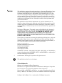
1
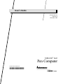
User’s Guide P/N 961-054-019 Revision A December 1999 NORANDR 6642 Pen Computer P/N 961-054-019 Revision A *961054019 " NOTICE This publication contains information proprietary to Intermec Technologies CorpoĆ ration. It is being supplied to you with the express understanding that the inĆ formation contained herein is for the benefit of the contracting party only, and may not be copied, distributed, or displayed to third parties without the express written consent of Intermec Technologies Corporation, and shall be returned to Intermec Technologies Corporation upon written request. If a purchase, license, or nondisclosure agreement has been executed, the terms of that agreement shall govern this document. This publication is furnished for information only, and the information in it is subject to change without notice. Although every effort has been made to provide complete and accurate information, Intermec Technologies Corporation assumes no responsibility or liability for any errors or inaccuracies that may appear in this document. Disclaimer of Warranties. The sample source code included in this document is presented for reference only. The code does not necessarily represent complete, tested programs. The code is provided AS IS WITH ALL FAULTS." ALL WARRANTIES ARE EXPRESSLY DISCLAIMED, INCLUDING THE IMPLIED WARRANTIES OF MERCHANTABILITY AND FITNESS FOR A PARTICULAR PURPOSE. We welcome your comments concerning this publication. Although every effort has been made to keep it free of errors, some may occur. When reporting a specific problem, please describe it briefly and include the book title and part number, as well as the paragraph or figure number and the page number. Send your comments to: Intermec Technologies Corporation Publications Department 550 Second Street SE Cedar Rapids, IA 52401 INTERMEC, NORAND, NOR*WARE, PEN*KEY, PEN*VIEW, and TRAKKER are registered trademarks and ANTARES, JANUS, and RAPIDREP are trademarks of Intermec Technologies Corporation. 1999 Intermec Technologies Corporation. All rights reserved. This publication printed on recycled paper. Acknowledgments Ethernet is a trademark of Xerox Corporation. Handwriter is a registered trademark of Communication Intelligence Corporation. Intel and Celeron are registered trademarks of Intel Corporation. Microsoft, MS, and MSĆDOS, and Windows, are registered trademarks and Visual Basic for Windows, and Windows for Pen are trademarks of Microsoft Corporation. PenRight! and PenRight! Pro are trademarks of PenRight Corporation. PKZIP and PKUNZIP are registered trademarks of PKWARE, Inc. SanDisk is a trademark of SanDisk Corporation. SystemSoft is a registered trademark and CardSoft and CardID are trademarks of SystemSoft Corporation. FCC Computer Compliance " NOTICE This equipment meets Class A digital device limits per Part 15 of FCC Rules. These limits protect against interference in a commercial area. It emits, uses, and can radiate radio frequency energy. If you do not install and use the equipment according to its instructions, it may interfere with radio signals. Using it in a residential area is likely to cause interference. If this occurs, you must correct the interference at your expense. FCC Computer Compliance " NOTICE This equipment meets Class B digital device limits per Part 15 of FCC Rules. These limits protect against interference in a residential area. It emits, uses, and can radiate radio frequency energy. If you do not install and use the equipment according to its instructions, it may interfere with radio signals. However, there is no guarantee that interference will not occur in a particular installation. If this equipment does cause harmful interference to radio or television reception, which can be determined by turning our equipment off and on, the user is encourĆ aged to try to correct the interference by one or more of the following measures: Reorient or relocate the radio or television receiving antenna. Increase the separation between the computer equipment and receiver. " Connect the equipment into an outlet on a circuit different from that to which the radio or television receiver is connected. " Consult the dealer or an experienced radio or television technician for help. Cet appareil numérique de la classe B respecte toutes les exigences du Reglèment sur le material boilleur du Canada. Une licence radio est requise pour ces dispositifs, sauf pour ceux installés tout à fait à l'intérieur d'un bâtiment. (Il faut que l'utilisateur obtienne cette licence.) " " Telephone Installation Warning Notices The following notices apply to equipment that may be connected to telephone lines or systems. For your personal safety, and to protect this equipment from potential electrical or physical damage, do NOT connect equipment to telephone lines or data communication equipment unless the following warnings have been read, understood, and complied with. " " " " " " Never install telephone wiring during a lightning storm. Never install telephone jacks in wet locations unless the jack is specifiĆ cally designed for wet locations. Never touch uninsulated telephone wires or terminals unless the teleĆ phone line has been disconnected at the network interface. Use caution when installing or modifying telephone lines. Avoid using a telephone (other than cordless type) during an electrical storm. There may be a remote risk of electric shock from lightning. Do not use the telephone to report a gas leak in the vicinity of the leak. Installation du téléphone : avertissements Les avertissements qui suivent s'appliquent à tout équipement qui peut être branché aux lignes ou systèmes téléphoniques. Pour votre sécurité personnelle et pour protéger l'équipement de tout dommage électrique ou physique potentiel, NE PAS brancher un ordinateur tablette électronique ou ses périphériques aux lignes téléphoniques ou équipements avant que les avertissements suivants aient été lus, compris et observés : " " " " " " Ne jamais installer de câblage téléphonique pendant un orage électrique. Ne jamais installer de prise téléphonique dans un endroit humide à moins que la prise ait été spécifiquement conçue pour être utilisée dans les endroits humides. Ne jamais toucher les fils de téléphone ou de l'équipement terminal non isolés à moins que la ligne téléphonique n'ait été débranchée de l'interĆ face réseau. User de prudence lors de l'installation ou de la modification de lignes téléphoniques. Éviter d'utiliser un téléphone (autre qu'un appareil téléphonique sans fil) pendant un orage électrique. Il pourrait y avoir un faible risque d'éĆ lectrocution par la foudre. Ne pas utiliser le téléphone afin de signaler une fuite de gaz à proximité de la fuite. B CAUTION: B CAUTION: WARNING: Intermec Technologies Corporation suggests you buy cables from us to connect with other devices. Our cables are safe, meet FCC rules, and suit our products. Other cables may not be tested. They may cause problems from electrostatic discharge or induced energy. Our warranties do not cover loss, injury, or damage from other cables. Intermec Technologies Corporation recommends that you only purchase Norand Mobile Systems Division certified modems. Intermec does not certify all modems available in the marketplace. Intermec does not warrant noncertified modems; furthermore, these modems may cause problems from electrostatic discharge and may not conform to FCC regulations. For a list of Norand Mobile Systems Division certified modems call Customer Support at 1-800-221-9236 in United States or (country code) 800-633-6149 in Canada. The lithium ion battery may explode if replaced incorrectly. Replace only with the same or equivalent type. ADVERTISSEMENT: La batterie au lithium peut exploser si elle est replacée de manière incorrecte. Elle ne doit être remplacée que par une batterie identique ou similaire. WARNING: Lithium ion batteries may explode or catch fire if overcharged due to improper dock installation. ADVERTISSEMENT: Les batteries au lithium peuvent exploser ou prendre feu si elles sont trop changées à cause d’une mauvaise installation de la station d’accueil. CONTENTS CONTENTS " " " " " " " " " " " " " " " " " " " " " " " " " " " " SECTION 1 . . . . . . . . . . . . . . . . . . . . . . . . . . . . . . . . . . . . . . . . . . 1-1 Overview . . . . . . . . . . . . . . . . . . . . . . . . . . . . . . . . . . . . . . . . . . . 1-1 Introduction: About this Manual . . . . . . . . . . . . . . . . . . . . . . Overview . . . . . . . . . . . . . . . . . . . . . . . . . . . . . . . . . . . . . . . . . . . The PEN*KEY 6642 Pen Computer . . . . . . . . . . . . . . . . Front View . . . . . . . . . . . . . . . . . . . . . . . . . . . . . . . . . . . . . . . . . . Power Button . . . . . . . . . . . . . . . . . . . . . . . . . . . . . . . . . . . . Power LED . . . . . . . . . . . . . . . . . . . . . . . . . . . . . . . . . . . . . . HDD LED . . . . . . . . . . . . . . . . . . . . . . . . . . . . . . . . . . . . . . . Battery LED . . . . . . . . . . . . . . . . . . . . . . . . . . . . . . . . . . . . . Speaker . . . . . . . . . . . . . . . . . . . . . . . . . . . . . . . . . . . . . . . . . Pen Stylus . . . . . . . . . . . . . . . . . . . . . . . . . . . . . . . . . . . . . . . Side Views . . . . . . . . . . . . . . . . . . . . . . . . . . . . . . . . . . . . . . . . . . Rear View . . . . . . . . . . . . . . . . . . . . . . . . . . . . . . . . . . . . . . . . . . . Infrared Communications Port . . . . . . . . . . . . . . . . . . . . Bottom View . . . . . . . . . . . . . . . . . . . . . . . . . . . . . . . . . . . . . . . . RESET Switch . . . . . . . . . . . . . . . . . . . . . . . . . . . . . . . . . . . Internal Battery Pack Charging . . . . . . . . . . . . . . . . . . . 1Ć1 1Ć2 1Ć2 1Ć4 1Ć5 1Ć6 1Ć6 1Ć6 1Ć6 1Ć7 1Ć8 1Ć9 1Ć9 1Ć10 1Ć11 1Ć12 SECTION 2 . . . . . . . . . . . . . . . . . . . . . . . . . . . . . . . . . . . . . . . . . . 2-1 Using the Pen Computer for the First Time . . . . . . . . . . . . 2-1 Connecting the AC Adapter . . . . . . . . . . . . . . . . . . . . . . . . . . . System Startup . . . . . . . . . . . . . . . . . . . . . . . . . . . . . . . . . . . . . . Startup . . . . . . . . . . . . . . . . . . . . . . . . . . . . . . . . . . . . . . . . . Pen Stylus Input . . . . . . . . . . . . . . . . . . . . . . . . . . . . . . . . . . . . Selecting an Item (pointing) . . . . . . . . . . . . . . . . . . . . . . . Moving Items/Resizing Windows . . . . . . . . . . . . . . . . . . Inputting Text . . . . . . . . . . . . . . . . . . . . . . . . . . . . . . . . . . . Connect Devices . . . . . . . . . . . . . . . . . . . . . . . . . . . . . . . . . . . . . Using the External Floppy Drive/Port Expander . . . . . . . . 2Ć2 2Ć3 2Ć3 2Ć4 2Ć4 2Ć4 2Ć4 2Ć6 2Ć7 PEN*KEY 6642 Pen Computer User’s Guide i CONTENTS Removing External Floppy Disk Drive/Port Expander Handling Floppy Disks . . . . . . . . . . . . . . . . . . . . . . . . . . . Inserting and Removing Floppy Disks . . . . . . . . . . . . . Formatting a Floppy Disk . . . . . . . . . . . . . . . . . . . . . . . . . 2Ć8 2Ć9 2Ć9 2Ć10 SECTION 3 . . . . . . . . . . . . . . . . . . . . . . . . . . . . . . . . . . . . . . . . . . 3-1 Software . . . . . . . . . . . . . . . . . . . . . . . . . . . . . . . . . . . . . . . . . . . . 3-1 General Information . . . . . . . . . . . . . . . . . . . . . . . . . . . . . . . . . 3Ć1 Software Included with the 6642 Pen Computer . . . . 3Ć1 Windows 98 . . . . . . . . . . . . . . . . . . . . . . . . . . . . . . . . . . . . . . . . . 3Ć1 Windows 98 Help . . . . . . . . . . . . . . . . . . . . . . . . . . . . . . . . . . . . 3Ć2 Help With Operating Procedures . . . . . . . . . . . . . . . . . . 3Ć2 Contents . . . . . . . . . . . . . . . . . . . . . . . . . . . . . . . . . . . . . . . . 3Ć3 Keyword . . . . . . . . . . . . . . . . . . . . . . . . . . . . . . . . . . . . . . . . 3Ć3 Help Regarding Items on the Screen . . . . . . . . . . . . . . . 3Ć4 PEN*KEY Utility Tool . . . . . . . . . . . . . . . . . . . . . . . . 3Ć5 Adjusting the Backlight and Checking the Remaining Battery Capacity . . . . . . . . . . . . . . . . . . . . . . . . . . 3Ć6 Suspend . . . . . . . . . . . . . . . . . . . . . . . . . . . . . . . . . . . . . 3Ć8 Setup . . . . . . . . . . . . . . . . . . . . . . . . . . . . . . . . . . . . . . . . 3Ć8 Keypad Assign . . . . . . . . . . . . . . . . . . . . . . . . . . . . . . . 3Ć9 Pen Calibration . . . . . . . . . . . . . . . . . . . . . . . . . . . . . . 3Ć10 Checking the Version of the PEN*KEY Tool . . . . . 3Ć12 Exiting the PEN*KEY Tool . . . . . . . . . . . . . . . . . . . . 3Ć12 CIC Handwriting Recognition . . . . . . . . . . . . . . . . . . . . . . . . 3Ć13 On Screen Keyboard . . . . . . . . . . . . . . . . . . . . . . . . . . 3Ć14 Right Mouse Button Setting . . . . . . . . . . . . . . . . . . . 3Ć14 ii SECTION 4 . . . . . . . . . . . . . . . . . . . . . . . . . . . . . . . . . . . . . . . . . . 4-1 Battery Use . . . . . . . . . . . . . . . . . . . . . . . . . . . . . . . . . . . . . . . . . 4-1 Battery Charge . . . . . . . . . . . . . . . . . . . . . . . . . . . . . . . . . . . . . . Charging Internal Battery Pack . . . . . . . . . . . . . . . . . . . Attaching the Expansion Battery Pack . . . . . . . . . . . . . Remaining Battery Pack Capacity Display . . . . . . . . . Confirming the Remaining Battery Pack Capacity Low Battery Warning . . . . . . . . . . . . . . . . . . . . . . . . . . . . Charging and Operating Times . . . . . . . . . . . . . . . . . . . . Battery Disposal . . . . . . . . . . . . . . . . . . . . . . . . . . . . . . . . . 4Ć1 4Ć2 4Ć3 4Ć6 4Ć6 4Ć8 4Ć9 4Ć10 PEN*KEY R 6642 Pen Computer User’s Guide CONTENTS SECTION 5 . . . . . . . . . . . . . . . . . . . . . . . . . . . . . . . . . . . . . . . . . . 5-1 Connecting Peripheral Equipment . . . . . . . . . . . . . . . . . . . . 5-1 Before connecting peripherals: . . . . . . . . . . . . . . . . . . . . Peripheral Equipment . . . . . . . . . . . . . . . . . . . . . . . . . . . . . . . Connectors . . . . . . . . . . . . . . . . . . . . . . . . . . . . . . . . . . . . . . . . . . Floppy Drive/Port Expander . . . . . . . . . . . . . . . . . . . . . . Audio I/O . . . . . . . . . . . . . . . . . . . . . . . . . . . . . . . . . . . . . . . . USB Connection . . . . . . . . . . . . . . . . . . . . . . . . . . . . . . . . . Keyboard/Mouse . . . . . . . . . . . . . . . . . . . . . . . . . . . . . . . . . SVGA Port . . . . . . . . . . . . . . . . . . . . . . . . . . . . . . . . . . . . . . Switching the Display . . . . . . . . . . . . . . . . . . . . . . . . . . . . Printer . . . . . . . . . . . . . . . . . . . . . . . . . . . . . . . . . . . . . . . . . . Installing a Printer Driver . . . . . . . . . . . . . . . . . . . . RS-232C . . . . . . . . . . . . . . . . . . . . . . . . . . . . . . . . . . . . . . . . IrDA Communications . . . . . . . . . . . . . . . . . . . . . . . . . . . . Preparing the 6642 and the Target Device . . . . . . Settings for Infrared Communication . . . . . . . . . . . Logical Port . . . . . . . . . . . . . . . . . . . . . . . . . . . . . . . . . . Disabling IR Communication . . . . . . . . . . . . . . . . . . Communication with a PC . . . . . . . . . . . . . . . . . . . . . PC Slot . . . . . . . . . . . . . . . . . . . . . . . . . . . . . . . . . . . . . . . . . . Removing a PC Card . . . . . . . . . . . . . . . . . . . . . . . . . . . . . . . . . Modem . . . . . . . . . . . . . . . . . . . . . . . . . . . . . . . . . . . . . . . . . . Connecting the Modem . . . . . . . . . . . . . . . . . . . . . . . . . . . Setting Communications Information . . . . . . . . . . Setting Communications Software . . . . . . . . . . . . . 5Ć1 5Ć2 5Ć3 5Ć3 5Ć3 5Ć4 5Ć4 5Ć5 5Ć5 5Ć6 5Ć6 5Ć6 5Ć7 5Ć7 5Ć7 5Ć7 5Ć8 5Ć8 5Ć9 5Ć10 5Ć11 5Ć12 5Ć12 5Ć12 PEN*KEY 6642 Pen Computer User’s Guide iii CONTENTS iv SECTION 6 . . . . . . . . . . . . . . . . . . . . . . . . . . . . . . . . . . . . . . . . . . 6-1 Troubleshooting . . . . . . . . . . . . . . . . . . . . . . . . . . . . . . . . . . . . 6-1 Problems on Start-up . . . . . . . . . . . . . . . . . . . . . . . . . . . . Problems with Display . . . . . . . . . . . . . . . . . . . . . . . . . . . . Problems with Hard Disk . . . . . . . . . . . . . . . . . . . . . . . . . Problems with Floppy Disk . . . . . . . . . . . . . . . . . . . . . . . Problems with Touch Panel . . . . . . . . . . . . . . . . . . . . . . . Problems with Peripherals . . . . . . . . . . . . . . . . . . . . . . . . Problems with Communications . . . . . . . . . . . . . . . . . . . Other Problems . . . . . . . . . . . . . . . . . . . . . . . . . . . . . . . . . . Factory Service . . . . . . . . . . . . . . . . . . . . . . . . . . . . . . . . . . Customer Response Center . . . . . . . . . . . . . . . . . . . . . . . 6Ć2 6Ć3 6Ć4 6Ć4 6Ć5 6Ć5 6Ć7 6Ć8 6Ć9 6Ć10 FIGURES Figure 1Ć1 The PEN*KEY 6642 Pen Computer . . . . . . . . . Figure 1Ć2 Front View . . . . . . . . . . . . . . . . . . . . . . . . . . . . . . . Figure 1Ć3 Power Button . . . . . . . . . . . . . . . . . . . . . . . . . . . . . Figure 1Ć4 Pen Removal . . . . . . . . . . . . . . . . . . . . . . . . . . . . . Figure 1Ć5 Side Views . . . . . . . . . . . . . . . . . . . . . . . . . . . . . . . Figure 1Ć6 Rear View . . . . . . . . . . . . . . . . . . . . . . . . . . . . . . . . Figure 1Ć7 Bottom View . . . . . . . . . . . . . . . . . . . . . . . . . . . . . Figure 1Ć8 Reset Switch . . . . . . . . . . . . . . . . . . . . . . . . . . . . . Figure 2Ć1 AC Adapter . . . . . . . . . . . . . . . . . . . . . . . . . . . . . . Figure 2Ć2 Pen Operation . . . . . . . . . . . . . . . . . . . . . . . . . . . . Figure 2Ć3 Connecting Devices . . . . . . . . . . . . . . . . . . . . . . . Figure 2Ć4 Floppy Drive/Port Expander . . . . . . . . . . . . . . . Figure 2Ć5 Floppy Drive/Port Expander Connector . . . . . Figure 2Ć6 Inserting and Removing a Floppy Disk . . . . . . Figure 4Ć1 Charging the Internal Battery . . . . . . . . . . . . . . Figure 4Ć2 Attaching the Expansion Battery . . . . . . . . . . . Figure 4Ć3 Attaching the Expansion Battery . . . . . . . . . . . Figure 4Ć4 Battery Pack Capacity . . . . . . . . . . . . . . . . . . . . . Figure 5Ć1 6642 Peripherals . . . . . . . . . . . . . . . . . . . . . . . . . . Figure 5Ć2 Side View Connections . . . . . . . . . . . . . . . . . . . . . Figure 5Ć3 SVGA Connector . . . . . . . . . . . . . . . . . . . . . . . . . . Figure 5Ć4 IrDA Port . . . . . . . . . . . . . . . . . . . . . . . . . . . . . . . . . Figure 5-5 Inserting the PC Card . . . . . . . . . . . . . . . . . . . . . Figure 5-6 Removing the PC Card . . . . . . . . . . . . . . . . . . . . Figure 5Ć7 Modem Connection . . . . . . . . . . . . . . . . . . . . . . . . 1Ć2 1Ć4 1Ć5 1Ć7 1Ć8 1Ć9 1Ć10 1Ć11 2Ć2 2Ć5 2Ć6 2Ć7 2Ć8 2Ć9 4Ć2 4Ć4 4Ć5 4Ć6 5Ć2 5Ć3 5Ć5 5Ć7 5Ć9 5Ć10 5Ć11 PEN*KEY R 6642 Pen Computer User’s Guide Section 1 Overview " " " " " " " " " " " " " " " " " " " " " " " " " " " " Introduction: About this Manual This manual is divided into six sections. " Section 1 Overview " Section 2 Using the Pen Computer for the First Time " Section 3 Software " Section 4 Operating the Pen Computer " Section 5 Connecting Peripheral Equipment " Section 6 Troubleshooting PEN*KEY R 6642 Pen Computer User’s Guide 1-1 Overview SECTION 1 Overview The PEN*KEYR 6642 Pen Computer Figure 1Ć1 The PEN*KEY 6642 Pen Computer The PEN*KEY 6642 Pen Computer is a compact, lightĆ weight mobile computer. It features: " " " " " " 1-2 Lightweight- 2.2lbs/1.0kg for portability and handling Thin styling- 0.75"/2.2cm Large 8.4"/24.7cm TFT color SVGA display 266MHz Celeron processor 4.3GB hard disk drive Windows 98 operating system PEN*KEY R 6642 Pen Computer User’s Guide SECTION 1 Overview " One Type II PC card slot " 21 key numeric keypad and navigation keys " Integrated 56K modem with RJ11 connector " Integrated USB interface standard " SVGA video output on DB-15 connector " 4Mbps IrDA infrared communications " AC '97 compliant audio, microphone, and monaural headset " Resistive touch panel and passive pen " Internal Li-Ion battery (1700mAh, 3 cell) " Floppy disk drive/port expander connector PEN*KEY R 6642 Pen Computer User’s Guide 1-3 Overview SECTION 1 Front View Power Button RJ11 Jack for Modem Display Power/ HDD LEDs Numeric Keypad Speaker Figure 1Ć2 Front View 1-4 PEN*KEY R 6642 Pen Computer User’s Guide SECTION 1 Overview Power Button In addition to turning the power on and off, the power button can be used as a suspend/resume switch. Figure 1Ć3 Power Button PEN*KEY R 6642 Pen Computer User’s Guide 1-5 Overview SECTION 1 Power LED When this LED is green, the pen computer is operating. When this LED is red, the pen computer is in the suspendĆ toĆRAM state. If this LED is off, the pen computer is either not operating or is in the suspendĆtoĆdisk state. HDD LED When the bottom green LED is flashing, the pen computer is accessing the hard drive. Battery LED When this LED is green, it indicates that power is being supplied by the AC adapter. In addition, if the expansion battery is installed on the pen computer, that battery pack is being charged too. When this LED is off, it indicates that the pen computer is running off battery power. When this LED is red, it indicates that the battery voltage has dropped and that there is little battery capacity remaining. Speaker The speaker outputs audio from the Windows sound system compatible chipset. When the audio input/output jack is used for headphones or line output, the internal speaker is disconnected. 1-6 PEN*KEY R 6642 Pen Computer User’s Guide SECTION 1 Overview Pen Stylus To remove the pen stylus, pull it straight out to the right. To place the pen back in the pen holder, align the projection on the pen with the groove in the pen holder and then gently slide the pen into the holder. Make sure that you push the pen all of the way in until it locks in place, so that it will not fall out unexpectedly. Figure 1Ć4 Pen Removal " NOTE: B CAUTION: Clean the tip of the pen stylus and wipe the screen with a soft lint– free cloth before use. If you use the pen on the screen while either is dirty, the display could become scratched or the pen might not move smoothly on the display surface. Use only the pen provided or your finger tip. Do not use a wood pencil, mechanical pencil, or any other sharp object. Doing so will scratch the screen. PEN*KEY R 6642 Pen Computer User’s Guide 1-7 Overview SECTION 1 Side Views Floppy Drive/ Port Expander Audio In/Out USB Connector Power In Pen Stylus PC Card Slot Fan Vent PC Card Slot Figure 1Ć5 Side Views 1-8 PEN*KEY R 6642 Pen Computer User’s Guide Ejector SECTION 1 Overview Rear View External Video Connector IrDA Port Figure 1Ć6 Rear View Infrared Communications Port This port is used by devices that use infrared communications, such as an IR desktop dongle or IR printers. " NOTE: If the infrared communications port is dirty, wipe it with a dry, soft cloth. Communications errors may result if the port is used while it is dirty. PEN*KEY R 6642 Pen Computer User’s Guide 1-9 Overview SECTION 1 Bottom View Expansion Battery Connector Cover Air Vents Reset Switch Figure 1Ć7 Bottom View The air vents allow the pen computer to dissipate internal heat. Do not block these vents for any length of time during operation. 1-10 PEN*KEY R 6642 Pen Computer User’s Guide SECTION 1 Overview RESET Switch If the power button does not work, press this switch with the tip of the stylus pen to reset the pen computer. RESET Switch Figure 1Ć8 Reset Switch PEN*KEY R 6642 Pen Computer User’s Guide 1-11 Overview SECTION 1 Internal Battery Pack Charging You can check the state of battery charge with the PKtools utility menu. " Tap on either the battery icon or the PEN*KEY tool icon in the Windows 98 taskbar, if they are displayed. When the system is running off of battery power: 1-12 PEN*KEY R 6642 Pen Computer User’s Guide Section 2 Using the Pen Computer for the First Time " " " " " " " " " " " " " " " " " " " " " " " " " " " " This section explains the necessary start up procedures. PEN*KEY R 6642 Pen Computer User’s Guide 2-1 Using the Pen Computer for the First Time SECTION 2 Connecting the AC Adapter B CAUTION: Always grasp the plug when plugging in or unplugging the power cord. Plug into the pen computer. Plug into an electrical outlet. Figure 2Ć1 AC Adapter " NOTE: 2-2 Leave the pen computer on the AC Adapter for 4 hours minimum to fully charge the batteries on first use. PEN*KEY R 6642 Pen Computer User’s Guide SECTION 2 Using the Pen Computer for the First Time System Startup Startup 1. Press the [POWER] button. The pen computer automatically executes its Power On Self-Test (POST). This test checks the pen computer's memory, system board and other devices before initiating normal operation. 2. Windows 98 starts up. 3. The default Windows 98 desktop displays on screen. PEN*KEY R 6642 Pen Computer User’s Guide 2-3 Using the Pen Computer for the First Time SECTION 2 Pen Stylus Input The PEN*KEY 6642 Pen Computer is equipped with a pen stylus to select items displayed on the LCD screen and to input text and drawings. Selecting an Item (pointing) To select an item, press the pen on the item to be selected and then remove the pen, without moving it on the display. This operation is called tapping", and is equivalent to clickĆ ing the left mouse button. This operation is used to select menu items, click buttons and select icons. Making two consecutive taps is called double-tapping." A double-tap is equivalent to double-clicking the left mouse button. This operation is used to start up programs or select functions. Moving Items/Resizing Windows To move an item, touch the pen to the item and then slide the pen over the screen (keeping it in contact with the screen) to the desired location. This operation is called dragging." This operation is equivalent to dragging with a mouse, and is used to move windows, etc. To resize a window, drag the window edge. Inputting Text If your application supports handwriting recognition, you may input text directly with the pen stylus, much like writing with paper and pencil. An optional keyboard is available for QWERTY input. " NOTE: 2-4 Because resistive film technology is used in the pen computers’ touch panel, the pen will not work properly if you place your hand on the screen while writing with the pen stylus. PEN*KEY R 6642 Pen Computer User’s Guide SECTION 2 Using the Pen Computer for the First Time Tap Double–Tap Drag Figure 2Ć2 Pen Operation PEN*KEY R 6642 Pen Computer User’s Guide 2-5 Using the Pen Computer for the First Time SECTION 2 Connect Devices The devices outlined in the figure below can be connected to the 6642 while the pen computer is powered on. Video Port PC Cards USB Port Audio I/O Jack Figure 2Ć3 Connecting Devices 2-6 PEN*KEY R 6642 Pen Computer User’s Guide SECTION 2 Using the Pen Computer for the First Time Using the External Floppy Drive/Port Expander You can use double-density 720K or high-density 1.44MB floppy disks with the external floppy disk drive/port expander. The keyboard/mouse port, RS-232C serial port and parallel port are available on the rear side of the floppy disk drive. Figure 2Ć4 Floppy Drive/Port Expander For more information about peripherals, refer to Section 5, Connecting Peripheral Equipment. PEN*KEY R 6642 Pen Computer User’s Guide 2-7 Using the Pen Computer for the First Time B CAUTION: B CAUTION: B CAUTION: SECTION 2 Do not place the floppy disk drive unit on its side or upside down. Do not press on the floppy disk drive unit; it may damage the drive or cause malfunction. Do not place the AC adapter on top of the floppy disk drive unit; it may cause the drive to malfunction. 1. Turn off the computer. 2. Open the cover of the external floppy disk drive/port expander cover on the right side of the 6642. 3. Connect the connector of the floppy disk drive unit to the 6642. Figure 2Ć5 Floppy Drive/Port Expander Connector Removal Removing External Floppy Disk Drive/Port Expander 1. Remove the floppy disk from the floppy disk drive. 2. Turn off the computer. 3. Disconnect the floppy disk drive unit by simultaneousĆ ly pressing the buttons on each side of the connector and pulling them out. See figure 2-5. 4. Close the cover of the floppy disk drive/port expander. 2-8 PEN*KEY R 6642 Pen Computer User’s Guide SECTION 2 Using the Pen Computer for the First Time Handling Floppy Disks " NOTE: " NOTE: " NOTE: " NOTE: Do not open the shutter and touch the disk inside, otherwise you will not be able to read or write data to the disk. Do not place floppy disks near magnetic or heat sources, or in direct sunlight or dusty environments. Never subject a disk to to sudden shocks or extreme vibration. Do not drop, bend, or place heavy objects on a disk. Do not spill liquids on a disk. Inserting and Removing Floppy Disks Hold the floppy disk with the arrow facing up and towards the drive. Slide the disk until it locks into place. " NOTE: Make sure the floppy disk is inserted correctly, not upside down. Don’t use excessive force when inserting the disk into the drive. Damage may result to the drive. Figure 2Ć6 Inserting and Removing a Floppy Disk Press the eject button firmly. The disk will pop out slightly. Remove it and store it properly. PEN*KEY R 6642 Pen Computer User’s Guide 2-9 Using the Pen Computer for the First Time SECTION 2 Formatting a Floppy Disk " NOTE: Formatting a floppy destroys all current data on the disk 1. Check to make sure the floppy is not write-protected. 2. Double-tap on My Computer on the Windows desktop. 3. From the capacity drop-down list, select 1.44MB or 720KB. 4. Tap Start to start formatting. " NOTE: 2-10 Intermec Technologies recommends that you regularly back up the data on your hard disk drive. Windows operating system has a backup function you can use to back up your data. See the online Help for details. PEN*KEY R 6642 Pen Computer User’s Guide Section 3 Software " " " " " " " " " " " " " " " " " " " " " " " " " " " " General Information This section explains the operating system software and the PEN*KEYR tool. Software Included with the 6642 Pen Computer The 6642 pen computer hard disk is preconfigured with the operating system and software before it is shipped from the factory. The folders on the hard disk are organized as shown below. " " Windows -Windows 98 system CIC PenX handwriting recognition software Windows 98 A computer's operating system is the basic software that conĆ trols the computer so that it can run application software. The 6642 pen computer uses Microsoft Windows 98 as its opĆ erating system. Application software must be compatible with this operating system in order to run on the pen computĆ er. PEN*KEY R 6642 Pen Computer User’s Guide 3-1 Software SECTION 3 Windows 98 Help The Help function is one of the main information resources for Windows 98. There are two types of help: help that exĆ plains specific operating procedures, and help that explains an item displayed on the screen. Help With Operating Procedures A list of help topics is displayed when you tap on Help" in the Start menu. The window changes to a search window if you tap on either the Contents" or the Keyword" tab at the top of the dialog box. 3-2 PEN*KEY R 6642 Pen Computer User’s Guide SECTION 3 Software Contents Use this to find information from a list of topics grouped by area. Keyword Use this to input the first few letters of the target word and to search for the desired information from an alphabetized list of keywords. PEN*KEY R 6642 Pen Computer User’s Guide 3-3 Software SECTION 3 Help Regarding Items on the Screen If a window has a [?] button, you can use it to see explanations of various items on the screen. Tap [?] and then tap the item in question. 3-4 PEN*KEY R 6642 Pen Computer User’s Guide SECTION 3 Software PEN*KEY Utility Tool The PEN*KEY tool allows the user to set the backlight, disĆ play current battery state, set suspend execution, reassign keypad functions, and change pen click volume from the Windows desktop. There are two methods for starting up the tool: 1. Tap on either the battery icon or the PEN*KEY tool icon in the Windows 98 taskbar, if they are displayed. 2. Tap the PEN*KEY tool in the Program menu under the Start menu. PEN*KEY R 6642 Pen Computer User’s Guide 3-5 Software SECTION 3 Adjusting the Backlight and Checking the Remaining Battery Capacity 1. Tap on the Backlight/Battery tab. 2. The backlight brightness can be set to one of four levels. To adjust the brightness, tap the desired level. 3. To adjust the brightness to that level, tap [OK]. To keep the previous level of brightness without making any changes, tap [Cancel]. When the system is running off of battery power: " NOTE: 3-6 The remaining battery capacity is not displayed if the AC adapter is connected. PEN*KEY R 6642 Pen Computer User’s Guide SECTION 3 Software The Autocheck button changes the brightness of the backlight when AC power is connected. If this box is checked, the backĆ light brightness cannot be adjusted. " NOTE: The backlight brightness can be adjusted temporarily by sliding the arrow to maximum, but with the “Auto” box checked, the brightness is set according to remaining battery power. PEN*KEY R 6642 Pen Computer User’s Guide 3-7 Software SECTION 3 Suspend Suspend to Disk and Suspend to RAM functions are advanced power management features which allow for maximum battery life for the 6642. " " Suspend to RAM- keeps system and graphics memory refreshed until the pen computer is reactivated. Suspend to Disk- entire system is saved to disk and all components of the pen computer are powered OFF until reactivated. Setup 1. Tap the Suspend operation tab. 2. Tap the radio button for the desired Suspend" mode. 3. The suspend operation is executed by tapping the Execute" button. 4. Change the default setting by tapping the OK" button. 3-8 PEN*KEY R 6642 Pen Computer User’s Guide SECTION 3 Software Keypad Assign The keypad assignments can be changed by doing the followĆ ing. For example, if an application requires function" keys, the 1" key could be changed to F1, the 2" key could be changed to F2", and so on. 1. Tap the Key Assign tab. 2. Tap the button for the key that you want changed. 3. Confirm which pen computer key is to be changed. 4. Tap the type: function key, alphanumeric key, or other. 5. Tap the key to be assigned. 6. After confirming the key to be changed, the type, and the assigned key, tap OK." To redo any of the selections, tap [Cancel]. " NOTE: The key changes are valid until you change them again. PEN*KEY R 6642 Pen Computer User’s Guide 3-9 Software SECTION 3 Pen Calibration Select Pen Align" from the Windows Start menu to begin pen calibration. Press in the center of the cross-hair target three times. Continue with the three remaining targets until the panel is calibrated. 3-10 PEN*KEY R 6642 Pen Computer User’s Guide SECTION 3 Software Pen Calibration (continued) Once complete, you can fine-tune the calibration by: " " " Changing the offset values of the cursor Changing the cursor speed Cancelling the calibration or restarting the procedure. PEN*KEY R 6642 Pen Computer User’s Guide 3-11 Software SECTION 3 Checking the Version of the PEN*KEY Tool " " NOTE: Tap the About tab. The version of the PEN*KEY utility tool is displayed. This is not the version number of the PEN*KEY hardware. Exiting the PEN*KEY Tool Tap either OK" or Cancel" at the bottom of the PEN*KEY tool screen. 3-12 PEN*KEY R 6642 Pen Computer User’s Guide SECTION 3 Software CIC Handwriting Recognition The CIC PENXR Handwriter Recognition System software (HRS) is preinstalled on the 6642 and is used with software products enabled for handwriting recognition and verification. PEN*KEY R 6642 Pen Computer User’s Guide 3-13 Software SECTION 3 On Screen Keyboard The on screen keyboard is available by default in the Windows 98 toolbar. Right Mouse Button Setting Click on the pen icon in the toolbar to change the mouse button assignment. Press the arrow button in the floating PenX toolbar to enable handwriting with the pen 3-14 PEN*KEY R 6642 Pen Computer User’s Guide Section 4 Battery Use " " " " " " " " " " " " " " " " " " " " " " " " " " " " Battery Charge Connect the AC adapter to the pen computer to charge the internal battery before use. The battery starts charging automatically when you conĆ nect the AC adapter to the pen computer. The approxiĆ mate charging times for the internal battery are 2.5 hours with the computer off, and 4 hours with the comĆ puter on. " NOTE: WARNING: The internal battery is not removable. Use of other AC adapters could result in fire or equipment damage. PEN*KEY R 6642 Pen Computer User’s Guide 4-1 Battery Use SECTION 4 Charging Internal Battery Pack Figure 4Ć1 Charging the Internal Battery 1. Plug the power cord to the AC adapter, then into an electrical outlet. 2. Connect the AC adapter to the pen computer. The power LED lights green. 4-2 PEN*KEY R 6642 Pen Computer User’s Guide SECTION 4 Battery Use Attaching the Expansion Battery Pack Attach or replace expansion battery pack described in the procedure below. See figure 4-2. 1. Turn off the pen computer and disconnect the AC adapter. 2. Place the pen computer face down on a flat surface. 3. Slide the battery pack connector cover door open to the right (Figure 4-2, step 1). 4. Attach the expansion battery pack to the pen computer by sliding it to the right. 5. Set battery locks (Figure 4-2 step 2). 6. Drop the battery pack straight into the tabs (Figure 4-3 step 3). 7. Lock the battery in place by sliding the battery pack latches to the right and down (Figure 4-3 step 4). " NOTE: To remove the expansion battery pack, simply reverse the installation procedure. PEN*KEY R 6642 Pen Computer User’s Guide 4-3 Battery Use B CAUTION: SECTION 4 If a battery pack is inserted incorrectly, damage to the battery pack or a fire could result. 1 Slide Battery Connector Cover Open to the Right 2 Set the Battery Locks as Shown Figure 4Ć2 Attaching the Expansion Battery 4-4 PEN*KEY R 6642 Pen Computer User’s Guide SECTION 4 Battery Use 3 Drop the Battery into the Tabs, Slide it to the Right 4 Lock the Battery, Setting the locks as Shown Figure 4Ć3 Attaching the Expansion Battery PEN*KEY R 6642 Pen Computer User’s Guide 4-5 Battery Use SECTION 4 Remaining Battery Pack Capacity Display Confirming the Remaining Battery Pack Capacity Figure 4Ć4 Battery Pack Capacity In Windows 98, the remaining battery pack capacity can be checked by the following method. " 4-6 The battery icon on the taskbar shows the remaining battery pack capacity. PEN*KEY R 6642 Pen Computer User’s Guide SECTION 4 Battery Use The internal battery gauge at the top indicates the remaining capacity of battery 1,(battery pack) and the battery gauge beĆ low indicates the remaining capacity of battery 2 (expansion battery pack). The remaining capacity of each battery is indicated by the following colors: " Light blue: 100% to 75% " Yellow: 75% to 50% " Red: 50% to 0% Tapping on the battery icon starts up the Pen*Key tool, which can be used to obtain more detailed battery informaĆ tion. In addition, the icon changes to an AC charger icon when the pen computer is being powered by the AC adapter. The remaining capacity of the battery packs can be checked by tapping on Control Panel" under Settings" in the Start menu and then double-tapping the Power Management" icon. If the AC adapter is connected, the remaining capacity of the battery packs is not displayed. " NOTE: " NOTE: The remaining capacity that is displayed is based on the battery voltage; some error in the reading might be present under certain conditions. The length of time a battery can power the system will also vary according to how the system is used and which applications are being run, so the indications of the remaining battery capacity should only be used as an approximation. If a battery pack is being recharged, the display of the remaining battery capacity will not be accurate. PEN*KEY R 6642 Pen Computer User’s Guide 4-7 Battery Use SECTION 4 Low Battery Warning The red LED turns on if the batteries will be completely drained within a few minutes. The operating system (Windows 98) and the hardware deterĆ mine low battery pack condition. The batteries will, of course, drain faster if the PC card slot is in use, the hard drive is accessed, floppy drive is in use, or other peripherals are attached. Continued operation of the pen computer in low battery condiĆ tion automatically executes a suspend-to-disk condition (reĆ gardless of setup setting), then shuts off the power. The contents of memory are saved in the suspendĆtoĆdisk partition on the hard disk. Afterwards, do not turn on the pen computer power until you have either connected the AC adapter or you have installed a fully charged external battery pack. 4-8 PEN*KEY R 6642 Pen Computer User’s Guide SECTION 4 Battery Use Charging and Operating Times The charging and operating times are based on the number of battery packs used, as shown in the following table. Number of Battery Packs Used Charging Time (from fully depleted to fully charged) Operating Time (from fully charged state) Internal battery pack Approximately 2.5 hours Approximately 1.5 to 2 hours Expansion battery pack Approximately 5 hours Approximately 2.5 to 4 hours The operating time varies according to the power manageĆ ment settings, the application software being used. The total charging time for both the internal and expansion battery packs connected to the pen computer is approxiĆ mately 6 hours with the unit OFF from empty to full. When the pen computer is turned on, it will take about approximately 8 hours. (Charge time depends on power the pen computer is using). B CAUTION: The lithium ion batteries used in these battery packs suffer a clear deterioration in performance if they are exposed to high temperatures for an extended period of time. These batteries should be stored in a cool, dry location. PEN*KEY R 6642 Pen Computer User’s Guide 4-9 Battery Use SECTION 4 Battery Disposal The 6642 pen computer contains or is supplied with a lithiumion battery. Lithium-ion batteries have a longer life due to their chemical makeup and do not need to be replaced as often. The internal battery must be replaced by an Intermec service center and the expansion battery pack may be ordered separately. Spent batteries should not be placed in common household waste. Contact local authorities for the location of a chemical waste collection program near you. 4-10 PEN*KEY R 6642 Pen Computer User’s Guide Section 5 Connecting Peripheral Equipment " " " " " " " " " " " " " " " " " " " " " " " " " " " " This chapter explains how to connect peripheral devices to the PEN*KEYR 6642 pen computer. Before connecting peripherals: 1. Turn off the power to the pen computer. 2. Connect the peripheral device to the pen computer. If the connector has screws, tighten them. 3. Turn on the peripheral device, then turn on the pen computer. PEN*KEY R 6642 Pen Computer User’s Guide 5-1 Connecting Peripheral Equipment SECTION 5 Peripheral Equipment USB Devices Type II PC Cards Audio I/O Floppy Drive/Port Expander Parallel Devices Serial Devices PS/2 Keyboard/Mouse Figure 5Ć1 6642 Peripherals 5-2 PEN*KEY R 6642 Pen Computer User’s Guide SECTION 5 Connecting Peripheral Equipment Connectors DC Power In Audio I/O USB Connector Floppy Drive/Port Expander Figure 5Ć2 Side View Connections Floppy Drive/Port Expander 1. Open the floppy drive/port expander cover on the right side of the pen computer. 2. Connect the cable from the floppy drive/port expanderĆ to the 6642 port expander connector. 3. Connect the desired peripheral device (PS/2, parallel or serial peripheral) to the floppy drive/port expander. 4. Apply power to the peripheral, if applicable, then the 6642. Audio I/O An internal mini speaker provides audio output from the integrated PCI audio controller on board the 6642. A 2.5mm bayonet socket connector allows for external microĆ phone input, and headphone outputs. PEN*KEY R 6642 Pen Computer User’s Guide 5-3 Connecting Peripheral Equipment " NOTE: SECTION 5 If external stereo speakers are connected to the pen computer, the audio is output from the right channel only. Adjust the sound volume in the operating system by tapping the speaker icon in the taskbar. USB Connection The USB (Universal Serial Bus) is a new generation port for PC97 system hardware design. This 4-pin port allows you to simultaneously connect multiple USB devices through daisychaining or through an external hub. The USB specification allows connection of up to 127 USB devices running at up to 12Mbps. USB connection allows you to disconnect/connect peripherals without turning off the pen computer. Keyboard/Mouse You can use a keyboard or external mouse with the 6642. One keyboard/mouse port is available when the external floppy disk drive is connected. A keyboard or mouse can also be connected via USB. B CAUTION: Do not connect or disconnect devices to the keyboard/mouse port while the 6642 is powered on. Doing so will cause improper operation. Read the manual provided with the device and make the necessary operating environment settings so that the device will be recognized. 5-4 PEN*KEY R 6642 Pen Computer User’s Guide SECTION 5 Connecting Peripheral Equipment SVGA Port The SVGA port connects an external monitor or projection deĆ vice to the 6642. You can run the LCD and the external moniĆ tor simultaneously. Video Connector Figure 5Ć3 SVGA Connector " NOTE: We do not recommend that you select “monitor only” mode. Switching the Display 1. Select Start menu. 2. Select Settings option. 3. In the Display Properties dialog box, select Settings, then select Advanced.... 4. Select NeoMagic tab, then tap Display Options. 5. Select the Monitor/LCD radio button. 6. Tap the OK button three times to return to the deskĆ top. PEN*KEY R 6642 Pen Computer User’s Guide 5-5 Connecting Peripheral Equipment SECTION 5 Printer You can connect a printer to a parallel port of the external floppy drive/port expander. " NOTE: Read the printer manual before setting up the printer. Check the setup utility for the LPT port settings before installing a printer driver. Installing a Printer Driver To use a printer, you need to install a printer driver. 1. In Windows Start menu, select Settings-Printers. 2. Double-tap Add Printer. The Add Printer appears. 3. Tap Next. 4. Confirm Local printer is selected and tap Next. 5. Select the manufacturer and the printer, and click Next. If you cannot find the model name of your printĆ er you will have to install the printer driver included with your printer. See your printer manual for deĆ tails. 6. Select LPT1 and tap Next. 7. Make sure the printer name is correct and tap Next. 8. Decide whether to print a test page, and tap Finish. Before printing a test page, make sure the printer is powered up and on line. RS–232C An RS-232C serial device, such as a modem or scanner can be connected to the 6642. The serial port is available on the exterĆ nal floppy drive/port expander. Check the setup utility for serial port settings on the 6642 and consult the user manual before connecting the device. 5-6 PEN*KEY R 6642 Pen Computer User’s Guide SECTION 5 Connecting Peripheral Equipment IrDA Communications The IR (infrared) port provides wireless file transfer between the 6642 and an IR-equipped computer or device. You can also print to an IR-equipped printer without connecting a printer cable. The IR mode supports two transfer rates: standard IR (SIR) mode at 115.2Kbps and Fast IR (FIR) mode at 4Mbps. Figure 5Ć4 IrDA Port Preparing the 6642 and the Target Device 1. Place the pen computer on a flat surface. 2. Position the target device so that its IR port is in a direct line of sight with that of the pen computer. 3. Adjust the distance between the IR ports to be less than 20 inches (50 cm). Settings for Infrared Communication 1. In Control Panel, select Infrared Monitor, Options and enable infrared communication. PEN*KEY R 6642 Pen Computer User’s Guide 5-7 Connecting Peripheral Equipment SECTION 5 Logical Port For some software, you may have to change the assignment of the logical port. 1. In the IR dialog box, select Ports. 2. Change the settings and tap OK. 3. When the message You have changed the infrared communication port appears, tap OK. Disabling IR Communication For IrDA communication to take place, the 6642 is continuously transmitting an Infrared signal to search for other IR devices. You can disable the IR transmissions by doing the following: 1. In the Start menu, select Settings, Control Panel. 2. Double-tap on the IR icon. 3. Turn off the infrared communication and tap OK. Communication with a PC To communicate with a personal computer: 1. Right tap on the file you want to send. 2. Select Send To - Infrared Recipient. The file you send will be saved in My Received Files in the C: drive of the target personal computer. If you have trouble sending the file, confirm that your pen computer and the target computer are located correctly. Double-tap My computer - Infrared Recipient, and check whether the name of the target computer appears in AvailĆ able infrared devices within range. If not relocate your comĆ pouter and the target computer. 5-8 PEN*KEY R 6642 Pen Computer User’s Guide SECTION 5 Connecting Peripheral Equipment PC Card Slot The PC Card slot houses one card slot that supports one Type II PC card. The 6642 supports the CardBus PC conĆ troller function, that allows 5V and 3V 32-bit CardBus and 16-bit PC cards including Zoom Video (ZV) function like MPEG PC cards. " NOTE: Before inserting a PC card, observe proper orientation and refer to the manual that comes with the PC card. 1. Insert the card into the PC Card slot, located on the left side of the unit, pushing it in as far as it will go. 2. When the card is inserted, the eject button pops out. 3. Fold the eject button into the side of the pen computer. Insert the card with the manufacturer’s label facing up. Figure 5-5 Inserting the PC Card PEN*KEY R 6642 Pen Computer User’s Guide 5-9 Connecting Peripheral Equipment SECTION 5 Removing a PC Card " 1) Tap the PC Card" icon in the system tray. " 2) Tap on the Stop" message that appears. " 3)Tap ATA device dialog box and wait for [OK]. " 4) Press the PC card slot eject button. When the edge of the card pops out of the slot, pull out the card and store it properly. Figure 5-6 Removing the PC Card " NOTE: 5-10 For Network PC Cards, first disable the device under the Windows 95/98 Control Panel, otherwise this may cause system problems. PEN*KEY R 6642 Pen Computer User’s Guide SECTION 5 Connecting Peripheral Equipment Modem The PEN*KEY 6642 contains an internal 56K V.90 Modem qualified for use with telephone systems in the United States and Canada. For other countries you may purchase an international PCMCIA Modem. RJ11 Connector Figure 5Ć7 Modem Connection " NOTE: This option is not available outside of North America. PEN*KEY R 6642 Pen Computer User’s Guide 5-11 Connecting Peripheral Equipment SECTION 5 Connecting the Modem " NOTE: " NOTE: The built–in modem on the 6642 is designed only for regular analog telephone lines. The modem may be damaged when connected to a digital ISDN terminal or digital PBX. Before connecting to a PBX, consult the PBX maintenance staff or its service company. If the electrical characteristics of your PBX are different from those of a regular analog line, the modem will not function properly. If you connect the modem to a digital PBX, both the modem and the PBX may be damaged. 1. Turn off the 6642. 2. Lift the cover of the modem jack located near the LEDs and connect the end of the modem cable to the modem jack. 3. Connect the other end of the cable to the telephone line. Setting Communications Information 1. In the Modem Properties dialog box, select Dialing Properties. 2. Set each item, following the instructions on the screen. Setting Communications Software 1. Set the COM port of the built-in modem from within the communications software you are using (assuming the default modem settings have not been changed). 2. Set parameters such as modem speed (baud rate) and line type (pulse or tone dialing). " NOTE: " NOTE: 5-12 Consult the manual or online help of the software you are using. Do not enter a suspend mode while using communication software. Exit other applications if you want to use fax communications. Communications speed varies with traffic, local telecommunications setup and ISP (Internet Service Provider) setup. PEN*KEY R 6642 Pen Computer User’s Guide Section 6 Troubleshooting " " " " " " " " " " " " " " " " " " " " " " " " " " " " Sometimes, a careful check will reveal that what you thought was a malfunction actually was not. Before requesting repairs, carefully consult this section and try to resolve the problem. PEN*KEY R 6642 Pen Computer User’s Guide 6-1 Troubleshooting SECTION 6 Problems on Start–up Why doesn't the power switch function? Confirm that the power cord is connected properly. " Connect another electrical device to the power outlet in order to confirm that power is live from the outlet. " Check that the batteries are not fully discharged; conĆ nect the pen computer to an electrical outlet. Why doesn't Windows start? " Check to see if the external floppy disk drive/port exĆ pander contains a non-system disk. Remove the floppy disk from the drive and press any key. " If booting from an external floppy disk drive, check to make sure the floppy disk is fully inserted into the drive. " Check to make sure the floppy is setup as the first boot device in the setup menu. " Confirm that the system files have not been deleted from the hard disk. " Depending on the state that the pen computer is in, the power button might not function. In that case, use the RESET switch on the bottom of the pen computer to turn off the power. Why do I get a non-system disk or disk error message? " " " " 6-2 There may be a non-bootable disk in the external floppy disk drive/port expander (either a defective disk or one without an operating system). Remove the disk. If the message appears when you try to boot from the hard drive, insert a bootable disk into the external floppy disk drive/port expander and check the status of your hard disk drive. Check whether the items Diskette A: or Hard Disk Type: are set up correctly in the Main section of the setup utility. PEN*KEY R 6642 Pen Computer User’s Guide SECTION 6 Troubleshooting Why do I get the message Operating System not found? " " Insert a boot up disk into the external floppy disk drive/port expander, then check the condition of the hard disk. Check the hard disk status from the setup utility. Check the size of the hard disk and make sure the Hard Disk Drive Type in the Main menu is set to Auto. Problems with Display Why is the screen blank? " " " " " Press any key to see if power management has turned off the screen to save power. Check the power LED to see if the pen computer has power. If you are using the internal battery pack, make sure it has charge remaining. If you are using the expanĆ sion battery pack, make sure it is connected correctly and has charge remaining. Press the power switch, wait 10 seconds and try turning the power back on. If you cannot restart the pen computer using the above procedure, press the reset button with the stylus pen, loĆ cated on the bottom of the 6642 and turn off the system. Wait 10 seconds and turn the pen computer back on. Why is there no display on the external monitor? " " " Confirm that the monitor is powered on. Confirm that the monitor is connected correctly. Check that the display setting is not set for external CRT monitor. PEN*KEY R 6642 Pen Computer User’s Guide 6-3 Troubleshooting SECTION 6 Why is the image on the external monitor display distorted? " " " " Check that the monitor is connected correctly. Make sure the CRT is not near any electric devices that have a stong magnetic fields such as a TV set, fan or radio. Do not share an outlet with a TV set or radio. Make sure the value of the Screen area in the Display Properties in Control Panel is equal to or lower than the resolution of the CRT monitor. Problems with Hard Disk Why can't I read or write data to or from the hard disk? " Confirm the drive and file names are correct. " Confirm the hard drive has enough free space. " The hard disk in your computer is formatted with FAT32. You cannot read or write data formatted in other operating systems which are not FAT32 compatĆ ible. Applications not FAT32 compliant may not work properly. Problems with Floppy Disk Why can't I use a floppy disk? " " " " " " 6-4 Confirm that the external floppy disk drive/port expander is correctly connected. Check that the floppy disk is inserted correctly. The floppy disk may be unformatted or corrupt. If you cannot write to a floppy disk, the disk may be write-protected. Eject the disk and check that the write-protect tab covers the detection hole. If you cannot write to a floppy disk, the disk may be full. Use another disk. Check that the floppy disk drive setting is set to 1.44MB in the setup utility. PEN*KEY R 6642 Pen Computer User’s Guide SECTION 6 Troubleshooting Problems with Touch Panel Why is the touch panel not functioning correctly? " " Confirm that the touch panel is correctly calibrated with the pen software. Run the calibration application from the program menu. Check to make sure the touch panel on the 6642 is clean and free of dirt. Check the pen stylus for dirt or foreign matter. Problems with Peripherals Why don't expansion or peripheral devices function? Confirm that they are correctly connected to your pen computer or the external floppy disk drive/port exĆ pander. " Confirm that the external floppy disk drive/port expander is connected correctly to the computer if peripheral devices are connected to the external floppy disk drive/port expander. " Confirm that drivers necessary for operating ports on the devices are installed. " There may not be a free IRQ (interrupt). Free up an IRQ from a built-in device. Why can't I print? " " " " " " " Make sure the printer is turned on and on-line. Check to see if the external floppy disk drive/port expander and the printer are connected correctly. Check to see if the printer has enough paper. Check to see if the printer driver is installed. Make sure the LPT port setting in the setup utility is set correctly. From the Start menu in Windows, select Settings Printers to confirm your printer is installed. If not, tap Add Printer to install your printer. PEN*KEY R 6642 Pen Computer User’s Guide 6-5 Troubleshooting SECTION 6 Why doesn't the device connected to the RS-232C serial port function? " Confirm that the device is correctly connected to the floppy disk drive/port expander with an appropriate cable. Confirm that the external floppy disk drive/port exĆ pander is connected correctly. " Confirm that the application program is compliant with the RS-232C standard interface. " Confirm that the COM1 port is not disabled by doing the following: 1. In the System Properties dialog box, select Device Manager. 2. Double-tap Ports, (COM&LPT); then double-tap ComĆ munications Port (COM1). 3. Make sure the item Disable in this hardware profile is unchecked. " Confirm that COM1 is not used by another application. " Confirm that the Serial Port is set up correctly in the setup utility. " 6-6 PEN*KEY R 6642 Pen Computer User’s Guide SECTION 6 Troubleshooting Problems with Communications Why can't I communicate through the built-in IR port? " " " " Confirm that the IR port of the 6642 is lined up with the IR port of the other device. These ports should be no more than 20 inches (50cm) apart without any obĆ stacles. Confirm that the IR communication is not turned off in the IR dialog box. Confirm that the item Mode of IR Port is set to IrDA in the setup utility. Turn off power management both in Windows and in the setup utility. Do not use the IR port under intense fluorescent light or near cellular phones. Why can't I communicate through the built-in modem? " (The built-in modem is not available in all countries) " " " " " " Confirm that the item Modem is enabled in the setup utility. Confirm the telephone line is properly connected to the modem jack. Confirm the dial setting of the communication softĆ ware are matched with the telephone line (Example: To access an outside line, first dial 7" for local 1" for long distance). Confirm that the network configuration is appropriĆ ate. Confirm the user name or password is correct. Confirm that the COM port in the communication softĆ ware is set appropriately. PEN*KEY R 6642 Pen Computer User’s Guide 6-7 Troubleshooting SECTION 6 Other Problems Why is the date or time incorrect? " " " " Correct the date and time using the Date/Time icon in the Windows Control Panel or the Main menu of the setup utility. Connect the AC adapter for at least eight hours in orĆ der to charge the backup battery. Use the Setup utility to set the correct date and time. If the correct date and time are still not displayed, conĆ tact an Intermec service center and have the backup battery on the system board replaced. Why is there no sound output? " Check the speaker icon fromthe taskbar icon and check the Windows volume control. Why can't I use a hardware device? " Make sure the device is not disabled from Windows by check ing the Device Manager tab in System Properties. Check to see that the Disable in this hardware profile box is unchecked. Why don't PC Cards work in MS-DOS mode? " Confirm that there are no conflicts involving COM3, which is used by cards, and COM1, which is used by other devices. This is because COM1 is already used by other pen computer devices. Use the setup utility to change the COM port settings. When a PC card uses COM3, set the COM Port" item to Disabled." Why don't PC Cards Function? " 6-8 Confirm that the PC Card is inserted right side up in the PC Card slot. Check that the card is inserted fully into the slot. If you are using a PC Card modem, check the modem cable connections. PEN*KEY R 6642 Pen Computer User’s Guide SECTION 6 Troubleshooting Factory Service If the unit is faulty, you can phone your designated InterĆ mec Service Center for repair advice, instructions, or to obĆ tain factory-quality repair service. Their telephone number and address can be found on the warranty card. Many failures may be repairable on-site, which is why it is important that you telephone first. When products must be shipped for repair: " " " Package the unit in the original shipping carton, if possible. Fill out a Product Service Information Card (a part of the warranty card). Send this card with the product. For warranty or technical assistance, telephone 1-800-755-5505. Customer Response Center The Customer Response Center (technical support) teleĆ phone number is 1-800-755-5055 (U.S.A or Canada) or 1-425-356-1799. The facsimile number is 1-425-356-1688. Email is [email protected]. If you email or fax a problem or question, include the following information in your message: " " " " Your name Your company name and address Phone number and email address to respond to Problem description or question. If the equipment was purchased through a Value-Added Reseller (VAR) include that information. PEN*KEY R 6642 Pen Computer User’s Guide 6-9 Troubleshooting SECTION 6 Web Site The Customer Support File Libraries, including Hot Tips and Product Awareness Bulletins, are available on the Internet. New users start at the Intermec web site: www.intermec.com. Choose Support," then Product Support," then Conference Area." Look on the main page for a link to register new cusĆ tomers. A PDF version of this manual will be available at this address: www.intermec.com/manuals/english.htm or choose Products" then Manuals" and English" from the opening page. Bulletin Board Service The Customer Support Bulletin Board (BBS), maintained by the Norand Mobile Systems Division of Intermec Technologies Corporation, provides software and documentation. " " 6-10 Phone Number: 319-369-3515 (14.4Kbps modem) 319-369-3516 (28.8Kbps modem) Protocol: Full duplex, ANSI or ANSI-BBS; 300 to 28,800 bps;v.32bis; 8 bits, no parity, 1 stop bit. For high-speed modems, disable XON/XOFF and enable RTS/CTS. PEN*KEY R 6642 Pen Computer User’s Guide