1
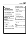
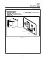
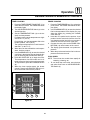
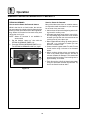
BCXĆ14G, BCXĆ14E, BXĆ14G, BXĆ14E,
CNVXĆ14G and CNVXĆ14E
INSTALLATION - OPERATION - MAINTENANCE
BCXĆ14G, BCXĆ14E, BXĆ14G, BXĆ14E,
CNVXĆ14G et CNVXĆ14E
MANUEL D'INSTALLATION - FONCTIONNEMENT - ENTRETIEN
BLODGETT COMBI
www.blodgett.com
44 Lakeside Avenue, Burlington, Vermont 05401 USA Telephone (800) 331Ć5842, (802) 860Ć3700 Fax: (802)864Ć0183
PN 39678 Rev C (4/07)
E 2007 - G.S. Blodgett Corporation
A PERSONAL WORD FROM BLODGETT COMBI
QUELQUES MOTS DE BLODGETT COMBI
Congratulations on your purchase of a BLODGETT Combi appliance. We
firmly believe that your choice has been a wise one, and trust you will reĆ
ceive many years of excellent service from your new Combi.
You will find that cooking with Combi appliances saves time, labor and
extensive cleaning of both the kitchen and the unit.
With Combi appliances the quality, taste, consistency, and look of your
food are improved, thus endorsing the policy to which we've always adĆ
hered: For Better Cooking!"
Once you've had a chance to use your Combi, please tell us, your dealer
and colleagues about any creative and interesting applications you have
discovered; exchange ideas with other users. Be sure to advise us or
your dealer immediately should any mechanical or technical problems
be encountered (...we're here to help!) and above all Enjoy Cooking the
BLODGETT Combi Way!
For information on cooking, please refer to our separate cooking guide.
Toutes nos félicitations sur votre achat d'appareil de Blodgett Combi.
Nous croyons fermement que votre choix est un choix raisonnable et
nous sommes certains que vous obtiendrez de nombreuses années
d'excellent service de votre nouveau four multiĆusages.
Vous allez découvrir que la cuisson dans les appareils Combi économise
le temps, le travail et le degré de nettoyage de l'appareil aussi bien que
de la cuisine.
Avec les appareil de Combi, la qualité, le goût, la consistence et l'apparĆ
ence des aliments sont améliorés, s'accordant, de ce fait, avec notre
politique "Pour une meilleure cuisson !"
Une fois que vous aurez eu la chance d'utiliser notre Combi, informez
nous, votre concessionnaire et vos collègues, de toutes les applications
nouvelles et intéressantes que vous avez découvertes ; échangez vos
idées avec d'autres utilisateurs. N'hésitez pas à nous prévenir, ou votre
concessionnaire, de tout problème mécanique ou technique que vous
pourriez rencontrer (... nous sommes ici pour vous aider) et parĆdessus
tout RégalezĆvous à cuisiner à la façon BLODGETT Combi!
Pour obtenir de plus amples informations sur l'art culinaire, veuillez conĆ
sulter notre livre de cuisine séparé.
IMPORTANT
WARNING: IMPROPER INSTALLATION, ADJUSTMENT, ALTERATION, SERVICE OR
MAINTENANCE CAN CAUSE PROPERTY DAMAGE, INJURY OR DEATH. READ THE
INSTALLATION, OPERATING AND MAINTENANCE INSTRUCTIONS THOROUGHLY
BEFORE INSTALLING OR SERVICING THIS EQUIPMENT
AVERTISSEMENT: UNE INSTALLATION, UN AJUSTEMENT, UNE ALTÉRATION, UN
SERVICE OU UN ENTRETIEN NON CONFORME AUX NORMES PEUT CAUSER DES
DOMMAGES À LA PROPRIÉTE, DES BLESSURES OU LA MORT. LISEZ ATTENTIVEĆ
MENT LES DIRECTIVES D'INSTALLATION, D'OPÉRATION ET D'ENTRETIEN AVANT
DE FAIRE L'INSTALLATION OU L'ENTRETIEN DE CET ÉQUIPEMENT.
INSTRUCTIONS TO BE FOLLOWED IN THE EVENT THE USER SMELLS GAS
MUST BE POSTED IN A PROMINENT LOCATION. THIS INFORMATION MAY BE
OBTAINED BY CONTACTING YOUR LOCAL GAS SUPPLIER.
LES INSTRUCTIONS À RESPECTER AU CAS OÙ L'UTILISATEUR PERÇOIT UNE
ODEUR DE GAZ DOIVENT ÊTRE AFFICHÉES DANS UN ENDROIT BIEN VISIBLE.
VOUS POUVEZ VOUS LES PROCURER AUPRÈS DE VOTRE FOURNISSEUR DE
GAZ LOCAL.
FOR YOUR SAFETY
Do not store or use gasoline or other flammable vapors or liquids in the vicinity
of this or any other appliance.
AVERTISSEMENT
Ne pas entreposer ni utiliser de l'essence ni d'autres vapeurs ou liquides inflamĆ
mables dans le voisinage de cet appariel, ni de tout autre appareil.
The information contained in this manual is important for the proper installation,
use, and maintenance of this oven. Adherence to these procedures and instrucĆ
tions will result in satisfactory baking results and long, trouble free service.
Please read this manual carefully and retain it for future reference.
Les informations données dans le présent manuel sont importantes pour installer,
utiliser et entretenir correctement ce four. Le respect de ces instructions et procéĆ
dures permettra d'obtenir de bons résultats de cuisson et une longue durée de serĆ
vice sans problèmes. Veuillez lire le présent manuel et le conserver pour pouvoir
vous y reporter à l'avenir.
Errors: Descriptive, typographic or pictorial errors are subject to correction. SpecificaĆ
tions are subject to change without notice.
Erreurs: Les erreurs de description, de typographie ou d'illustration font l'objet de
corrections. Les caractéristiques sont sujettes à modifications sans préavis.
Model/Modèl:
Your Service Agency's Address:
Adresse de votre agence de service:
Serial Number/Numéro de série:
Your appliance was installed by/
Installateur de votre four:
Your oven's installation was checked by/
Contrôleur de l'installation de votre four:
Table of Contents/ Table des Matières
Introduction
Introduction
The Blodgett CombiĆOven/Steamer . . . . . 2
Le fourĆétuveur Combi de Blodgett . . . . . . 36
Description of the CombiĆOven/Steamer . 3
Description du fourĆétuveur Combi . . . . . . 37
Oven Features . . . . . . . . . . . . . . . . . . . . . . . 4
Fonctionnalités du four . . . . . . . . . . . . . . . . 38
Installation
Installation
Agency Approvals . . . . . . . . . . . . . . . . . . . . 5
Certifications . . . . . . . . . . . . . . . . . . . . . . . . . 39
Owner's Responsibilities . . . . . . . . . . . . . . . 6
Responsabilités du propriétaire . . . . . . . . . 40
Oven Location and Ventilation . . . . . . . . . . 8
Emplacement du four et mise de niveau et
Ventilation . . . . . . . . . . . . . . . . . . . . . . . . . . . 42
Leg Attachment . . . . . . . . . . . . . . . . . . . . . . 9
Caster Attachment . . . . . . . . . . . . . . . . . . . . 10
Stacking . . . . . . . . . . . . . . . . . . . . . . . . . . . . . 11
Plumbing Connections . . . . . . . . . . . . . . . . 13
Electrical Connections . . . . . . . . . . . . . . . . 14
Gas Connections . . . . . . . . . . . . . . . . . . . . . 15
Gas Hose Restraint . . . . . . . . . . . . . . . . . . . 17
Adjustments . . . . . . . . . . . . . . . . . . . . . . . . . 18
Final Check Lists . . . . . . . . . . . . . . . . . . . . . 19
Operation
Safety Information for Gas Units . . . . . . . . 20
Power Switches . . . . . . . . . . . . . . . . . . . . . . 21
Standard Controls for Models
BCXĆ14 and BXĆ14 . . . . . . . . . . . . . . . . . . . . 22
Standard Controls for Models CNVXĆ14 . . 25
Maintenance
Spray Bottle Operating Procedure . . . . . . 27
Cleaning and Preventive Maintenance . . . 28
Deliming (BCXĆ14 units only) . . . . . . . . . . . 30
Communication (BCXĆ14 and BXĆ14
units only) . . . . . . . . . . . . . . . . . . . . . . . . . . . 33
Montage des pieds . . . . . . . . . . . . . . . . . . . 43
Accessoire des roulettes . . . . . . . . . . . . . . 44
Superposition . . . . . . . . . . . . . . . . . . . . . . . . 45
Raccordement du système de détartrage
Unités BCXĆ14 seulement . . . . . . . . . . . . . . 46
Raccordement de la plomberie . . . . . . . . . 47
Raccordement à l'électricité . . . . . . . . . . . . 48
Raccordement au gaz . . . . . . . . . . . . . . . . . 49
Câble d'immobilisation du tuyau à gaz . . 51
Ajustements . . . . . . . . . . . . . . . . . . . . . . . . . 52
Liste de vérification finale . . . . . . . . . . . . . . 53
Fonctionnement
Renseignements sur la sécurité des
appareils au gaz . . . . . . . . . . . . . . . . . . . . . . 55
Interrupteurs généraux . . . . . . . . . . . . . . . . 56
Commandes standard for Model
BCXĆ14 and BXĆ14 . . . . . . . . . . . . . . . . . . . . 57
Commandes standard pour les modèles
CNVXĆ14 . . . . . . . . . . . . . . . . . . . . . . . . . . . . 60
Entretien
Procédure de fonctionnement du
pulvérisateur . . . . . . . . . . . . . . . . . . . . . . . . . 62
Nettoyage et entretien préventif . . . . . . . . 63
Détartrage (Unités BCXĆ14 seulement) . . 66
Communications (Unités BCXĆ14 et
BXĆ14 seulement) . . . . . . . . . . . . . . . . . . . . . 69
Introduction
The Blodgett CombiĆOven/Steamer
The Blodgett CombiĆOven/Steamer offers a comĆ
pletely new method of cooking. With the Oven/
Steamer you have the choice of two cooking proĆ
cesses: Steam and Hot Air, either...
D
D
D
You ācan also āuse ātwo āor āthree functions in seĆ
quence during one cooking process. We call this:
D
D
Separately
Combined, or
In Sequence
D
The combination of circulating hot air and steam
in the space saving, high performance CombiĆ
Oven/Steamer leads to improvements in the folĆ
lowing areas:
And for easy operation you can choose from three
modes:
D
D
Steam &
Hot Air
D
In the Steam mode you can:
steam
stew
blanch
poach
reheat
thaw
preserve
D
bake
gratinate
In the Combination Steam and Hot Air mode you
can:
defrost
reheat
roast
bake
increased productivity in the kitchen
a reduction in capital expenditures for multiple
equipment replacement
a wider range of menu choices
a simplified cleaning process
The work process is simplified since products are
prepared on or in steam table āpans āand trays.
Food can be cooked, stored, and transported with
āthe āsame p
ā ans. S
ā mall a
ā mounts of product can be
processed efficiently; preĆcooked and conveĆ
nience foods can be reheated within minutes.
āMany frozen foods can be processed without preĆ
thawing. This flexibility in preparation reduces the
need for kettles and steam tables since there is no
need for large amounts of food to be kept warm for
long periods of time.
reconstitute
simmer
braise
In the Hot Air mode you can:
roast
grill
broil
combiĆsteaming
combiĆroasting
combiĆbaking
Today the improvement of food quality is more imĆ
portant than ever. Vegetables are cooked in the
Blodgett CombiĆOven/Steamer without water at
the optimal temperature of just under 100_C
(212_F), maintaining valuable vitamins, minerals,
nutrients and trace elements. Cooking meat in the
Combi results in less shrinkage and a firmer, juicier
product. The Blodgett CombiĆOven/Steamer is
being used more and more for baking. Steam and
Hot āAir āmodes āmake āit āa āgeneral āpurpose baking
appliance.
rethermalize
forced steaming
NOTE: CNVX models only operate in hot air mode.
2
Introduction
Description of the CombiĆOven/Steamer
ABOUT THE OVEN/STEAMER
OVEN/STEAMER OPERATION
Blodgett CombiĆOven/Steamers are quality proĆ
duced using highĆgrade stainless steel with first
class workmanship.
The practical oven door, with a viewing window,
has a wide swing radius and handle which can be
operated easily, even with wet or greasy hands.
The multiple speed fan, which is guarded against
accidental finger contact, is driven by a quiet and
powerful motor. The condenser draws out excess
steam from the appliance. Condensation and
waste water, which result during steaming and
cleaning, are continuously drained.
Ease of operation is guaranteed through the simĆ
ple arrangement of the controls. Graphic symbols
make the appliance easy for even inexperienced
kitchen staff to operate. The Steam On Demand
feature allows the operator to add steam at any
time while operating in either the Hot Air or Combi
modes. This feature is excellent for baking as well
as roasting operations. A fourth function, the Cool
Down mode, allows the oven cavity to cool down
rapidly with the door opened.
The use of high quality insulation impedes excesĆ
sive heat radiation and saves energy.
The Oven/Steamer has optional adjustable legs
which adapt easily to slightly uneven surfaces and
optional floor stands which are designed for use
with all of the table models.
Cleaning is kept to a minimum. The interior is
sprayed with a selfĆacting cleaning solution which
interacts with steam to easily remove crusts and
stains. The oven is designed for easy care and is
welded water tight so that the internal cooking
cavity may be rinsed with a hose after the steam
cleaning process.
The high performance fresh steam generator with
its control system makes it possible to enjoy all of
the advantages of a high quality steamer at the
flick of a switch. Fresh steam enters the oven cavĆ
ity without pressure and is circulated at high
speed. This process enables quick and gentle
cooking and ensures high quality food while proĆ
viding convenient working methods. The steam
generator is completely automatic and protected
from running dry.
3
Introduction
Oven Features
4
1
3
5
6
2
BCXĆ14G shown
Figure 1
1
Control Panel
4
Steam Vent
2
Oven Door
5
Circuit Breaker
3
Door Handle
6
Heat Cutoff
4
Installation
Agency Approvals
THE INSTALLATION INSTRUCTIONS CONĆ
TAINED HEREIN ARE FOR THE USE OF QUALIĆ
FIED INSTALLATION AND SERVICE PERSONNEL
ONLY. INSTALLATION OR SERVICE BY OTHER
THAN QUALIFIED PERSONNEL MAY RESULT IN
DAMAGE TO THE OVEN AND/OR INJURY TO
THE OPERATOR.
U.S. and Canadian Installations
Installation must conform with local codes, or in
the absence of local codes, with the National Fuel
Gas Code, NFPA54/ANSI Z223.1-Latest Edition,
the Natural Gas Installation Code CAN/CGAĆ
B149.1 or the Propane Installation Code, CAN/
CGAĆB149.2 as applicable.
Reference: National Electrical Code, ANSI/NFPA
70-Latest Edition and/or Canadian Electrical
Code CSA C22.1 as applicable.
Qualified installation personnel are individuals, a
firm, a corporation, or a company which either in
person or through a representative are engaged
in, and are responsible for:
D
D
This equipment is to be installed in compliance
with the Basic Plumbing Code of the Building OffiĆ
cials and Code Administrators International Inc.
(BOCA) and the Food Service Sanitation Manual of
the Food and Drug Administration (FDA).
The installation or replacement of gas piping.
The connection, installation, repair or servicing
of equipment.
The installation of electrical wiring from the elecĆ
tric meter, main control box or service outlet to
the electric appliance.
General Export Installations
Installation must conform with Local and National
installation standards. Local installation codes and/
or requirements may vary. If you have any questions
regarding the proper installation and/or operation of
your appliance, please contact your local distributor.
If you do not have a local distributor, please call
Blodgett Combi at 0011Ć802Ć860Ć3700.
Qualified installation personnel must be experiĆ
enced in such work, be familiar with all precauĆ
tions required and have complied with all requireĆ
ments of state or local authorities having
jurisdiction.
5
Installation
Owner's Responsibilities
Installation responsibilities prior to service
startup inspection
1. Oven(s) are uncrated, stacked (if applies) and
put in place.
NOTE: Please refer to Leg Attachment and
Stacking.
You are entitled to a free startĆup inspection serĆ
vice by our factory ASAP. Before a factory repreĆ
sentative arrives to perform a startup procedure,
the owner must already have satisfied the followĆ
ing requirements.
Maximum shelf loading - 60 lbs (27.3 Kg)
PLUMBING SPECIFICATIONS
BCXĆ14G/AA, BCXĆ14E/AA
BXĆ14G/AA, and BXĆ14E/AA
CNVXĆ14G/AA
CNVXĆ14E/AA
WATER
Water Pressure
30 PSI (207 kPa) minimum
50 PSI (345 kPa) maximum
Water Connection
3/4" garden hose - Hot and
Cold water
Water Pressure
Regulator Setting
Preset to 30 PSI (207 kPa)
Minimum Requirements
TDS - less than 100 parts per million
3/4" garden hose for spray
hose - Cold water only
Total Hardness - 80Ć120 parts per million
Chlorides - less than 30 parts per million
pH Factor - 7.0Ć8.0
DRAINAGE
Drain Type
Atmospheric Vented Drain
Drain Connection
2.00" (50.8mm) Copper
Avg Water Drain Temp.
Approximately 140_F (60_C)
6
Installation
Owner's Responsibilities
RATINGS - GAS APPLIANCES
Gas Type
Gas Input
Voltage
Phase
Amps
Motor
Natural
Steam - 50,000 BTU/Hr
Hot Air - 65,000 BTU/Hr
Total - 115,000 BTU/Hr
120
1
20
3/4HP 208Ć240VAC, 3 phase,
50/60 Hz
Propane
Steam - 48,000 BTU/Hr
Hot Air - 65,000 BTU/Hr
Total - 113,000 BTU/Hr
120
1
20
3/4HP 208Ć240VAC, 3 phase,
50/60 Hz
BCXĆ14G/AA
3/4" NPT connector for all U.S. and Canadian installations
BXĆ14G/AA and CNVXĆ14G/AA
Natural
Hot Air - 65,000 BTU/Hr
120
1
20
3/4HP 208Ć240VAC, 3 phase,
50/60 Hz
Propane
Hot Air - 65,000 BTU/Hr
120
1
20
3/4HP 208Ć240VAC, 3 phase,
50/60 Hz
3/4" NPT connector for all U.S. and Canadian installations
RATINGS - ELECTRIC APPLIANCES
BCXĆ14E/AA, BXĆ14E/AA and CNVXĆ14E/AA
Voltage
Hz
Phase
Max Load (amps)
L1
L2
L3
Motor
208
60
3
53
53
50
3/4 HP 208Ć240VAC, 50/60 Hz
240
60
3
46
46
43
3/4 HP 208Ć240VAC, 50/60 Hzz
480
60
3
23
23
21
3/4 HP 208Ć240VAC, 50/60 Hz
415
50
3
26.5
26.5
24.1
3/4 HP 208Ć240VAC, 50/60 Hz
7
Installation
Oven Location and Ventilation
OVEN LOCATION
VENTILATION
The well planned and proper placement of your
oven will result in long term operator convenience
and satisfactory performance.
The necessity for a properly designed and inĆ
stalled ventilation system cannot be over emphaĆ
sized. The ventilation system will allow the unit to
function properly while removing unwanted vaĆ
pors and products of combustion from the operatĆ
ing area.
Certain minimum clearances must be maintained
between the oven and any combustible or nonĆ
combustible construction. See the table below.
The appliance must be vented with a properly deĆ
signed mechanically driven exhaust hood. The
hood should be sized to completely cover the
equipment plus an overhang of at least 6" (15 cm)
on all sides not adjacent to a wall. The capacity of
the hood should be sized appropriately and proviĆ
sions made for adequate makeup air.
In addition, the following clearances are recomĆ
mended for servicing.
D
D
Oven body sides - 12" (30cm)
Oven body back - 12" (30cm)
NOTE: On gas models, routine servicing can usuĆ
ally be accomplished within the limited
movement provided by the gas hose reĆ
straint. If the oven needs to be moved furĆ
ther from the wall, the gas must first be
turned off and disconnected from the oven
before removing the restraint. Reconnect
the restraint after the oven has been reĆ
turned to its normal position.
WARNING!!
Failure to properly vent the oven can be
hazardous to the health of the operator;
and will result in operational problems,
unsatisfactory baking, and possible damĆ
age to the equipment. Damage sustained
as a direct result of improper ventilation
will not be covered by the Manufacturer's
warranty.
Left Side Heat Shield
Heat sources should not be near the air vents loĆ
cated on the left hand side of the gas appliance.
Oven
M d l
Model
When installed in the Commonwealth of MassaĆ
chusetts, this appliance must be interlocked with
the hood exhaust system so that the appliance
may be operated only when the hood exhaust sysĆ
tem is running.
MINIMUM REQUIRED
CLEARANCES
Right
Side
Left
Side
Back
BCXĆ14G
6"
BXĆ14G
(152.4mm)
CNVXĆ14G
0"
(0mm)
6"
(152.4mm)
BCXĆ14E
BXĆ14E
CNVXĆ14E
0"
(0mm)
6"
(152.4mm)
0"
(0mm)
U.S. and Canadian Installations
Refer to your local ventilation codes. In the abĆ
sence of local codes, refer to the National ventilaĆ
tion code titled, Standard for the Installation of
Equipment for the Removal of Smoke and Grease
Laden Vapors from Commercial Cooking EquipĆ
ment", NFPAĆ96Ć Latest Edition.
General Export Installations
Installation must conform with Local and National
installation standards. Local installation codes
and/or requirements may vary. If you have any
questions regarding the proper installation and/or
operation of your unit, please contact your local
distributor. If you do not have a local distributor,
please call Blodgett Combi at 0011Ć802Ć860Ć3700.
8
Installation
Leg Attachment
LEG OPTIONS
ATTACHMENT
Legs are available in 4" (101mm), 6" (152mm) āor
25" (ā635mm) ālengths āor ālow profile casters.
1. Align the threaded stud on one of the front
legs to the bolt h
ā oleā locatedāā ināā tā heāā bottom c
ā orĆ
ner of the appliance. Turn the leg clockwise
and tighten to the nearest full turn.
2. Align the leg plate holes with the bolt holes.
Secure with the two 1/2" bolts provided.
3. Repeat the above steps with the other front
leg. If low profile casters are used, install them
with the locking casters in the front of the oven.
The rear casters do not lock. Ensure that the
locks are set on the front casters.
4. Tip the oven up on the newly installed front
legs. If ācastersā are āused, checkā thatā the locksā
areā setā on tā heā front casters. R
ā epeat tā he above
steps for the rear legs.
5. Level the oven by screwing the adjustable feet
in or out as necessary.
D
D
D
The 4" (101mm) legs may be used when mountĆ
ing on a counter.
The 6" (152.4mm) legs are used on the lower
section of a double stacked appliance.
The 2
ā 5" (635mm) legs are used for a single apĆ
pliance located on the floor.
NOTE: For safety reasons, casters must not be
used with the 25" (635mm) legs.
25" (635mm) Adjustable Leg
6" (152,4mm) Adjustable Leg
Low Profile Casters
4" (101mm) Leg
Figure 2
Figure 3
9
Installation
Caster Attachment
1. Place a level on the floor where the casters are
to rest.
2. Place shims under the low side until it is level.
3. Mount the shims between the casters and the
oven as follows:
a.) Align the shims and caster holes with the
bolt holes.
b.) Secure with the 1/2" bolts provided.
NOTE: Install them with the locking casters in
the front of the oven. The rear casters
do not lock. Ensure that the locks are
set on the front casters.
4. Tip the oven up on the newly installed casters.
Add shims as necessary
Floor
Exaggerated for clarity
Figure 4
10
Installation
Stacking
WARNING!!
Stacking should be performed by qualiĆ
fied installation personnel only. The
ovens are heavy. Take care to use proper
tools and techniques when lifting and
stacking units.
1. Attach the legs or casters to the bottom oven.
See page 9 or 10.
2. Place the top oven on the bottom oven. Be
sure all four sides are flush.
3. Remove left side oven panels.
4. Bolt the two ovens together from underneath
into the two threaded nut retainers.
5. GAS APPLIANCES ONLY: Attach the flue
vents and gas manifold as shown.
Hot Air Flue
Steam Generator Flue
(BCXĆ14 only)
Left Side of Ovens
with Side Panels
Removed
Threaded
Nut Retainer
Bolt
Gas Manifold
Rear View BCXĆ14G
Figure 5
11
Installation
Deliming System Connection (BCXĆ14 units only)
1. Push deliming tube onto barbed fitting on
oven back.
3. Insert the end of the deliming tube with the jug
weight into the deliming solution reservoir.
Figure 6
Figure 8
2. Cut deliming tube to length using the bottom
of the deliming fluid reservoir in its mounted
position as a guide. Install the jug weight on
the deliming fluid reservoir end of the deliming
tube.
4. Prime the pump by placing oven in COOL
DOWN mode with the oven on and press and
hold the STEAM ON DEMAND button. Watch
for deliming solution to flow through tube. This
will tell you the pump is working correctly. ReĆ
lease the STEAM ON DEMAND button once
deliming solution has reached the oven back.
NOTE: If needed use supplied hose retainers and
self drilling screws to route the deliming
tube away from hot exhaust ports.
Figure 7
12
Installation
Plumbing Connections
WATER CONNECTION
trapped water to accumulate. The customer must
supply the piping from the oven to the drain.
NOTE: Hot water maximizes steam production but
is not required. Cold water may be supplied
to both inlets if hot water is not available.
Specific water/drain connection for City of Los
Angeles
1. Each drain line from the appliance shall be
routed without dips or sags to terminate above
the flood level rim of an approved indirect waste
receptor.
2. The appliance shall be installed in accordance
with the manufacturer's printed instructions
and the LAPC and LAMC, 1999 editions.
3. A backflow protection device may be required
by local codes. If so, install on the potable water
system directly ahead of the appliance. The
backflow protection device shall be any of the
following: an approved pressure type vacuum
breaker installed at least 12" above the highest
point of use, a double check valve backflow preĆ
venter or a reduced pressure principal backflow
preventer.
Connect the appliance to quality water via a presĆ
sure hose with 3/4" GHT (19mm) couplings. See
Figure 9 for connections. A shut off valve is to be
provided adjacent to the oven.
WARNING!!
Operating the appliance without the water
regulator installed will invalidate your warĆ
ranty.
This product must be installed by a licensed
Plumber or Gas Fitter when installed within the
Commonwealth of Massachusetts.
DRAIN CONNECTION
The drain should be run to an open floor drain
avoiding flexible hose that could sag and allow
Gas
connection
BCXĆ14G and BXĆ14G
BCXĆ14E and BXĆ14E
Electrical
connection
Filtered/boiler
connection
Unfiltered/condensate
and spray hose
connection
CNVXĆ14G
CNVXĆ14E
Figure 9
13
Installation
Electrical Connections
ELECTRICAL CONNECTION
Electric Models
All Models
A strain relief for the power supply cord is provided.
The installer must supply a cord that meets all Local
and National installation standards.
NOTE: Electrical connections must be performed
by a qualified installer only.
Before making any electrical connections to these
appliances, check that the power supply is adeĆ
quate for the voltage, amperage, and phase reĆ
quirements stated on the rating name plate
mounted on the appliance.
The circuit breaker that is used to provide power
to this appliance must have a minimum of .076"
(3mm) contact spacing. The circuit breaker must
meet all Local and National installation standards.
All appliances must be installed in accordance
with Local or National Electrical codes.
A wiring schematic is located on the inside of the
removeable side panel.
NOTE: Disconnect the power supply to the apĆ
pliance before servicing.
WARNING!!
Improper installation may invalidate your
warranty.
14
Gas Models
U.S. and Canadian Installations
A power cord (115V or 230V) is supplied with a
plug attached. Plug the power cord into the deĆ
sired receptacle.
WARNING!!
If the supply cord is damaged, it must be
replaced by a special cord or assembly
available from the manufacturer or its serĆ
vice agent.
Installation
Gas Connections
GAS PIPING
A properly sized gas supply system is essential for
maximum oven performance. Piping should be
sized to provide a supply of gas sufficient to meet
the maximum demand of all appliances on the line
without loss of pressure at the equipment.
Maximum Capacity of Iron Pipe in Cubic Feet
of Natural Gas Per Hour
(Pressure drop of 0.5 Inch W.C.)
Nominal Size, Inches
Pipe
Length
(ft)
3/4"
1"
Example:
10
360
680
1400
2100
3950
NOTE: BTU values in the following example are
for natural gas.
20
250
465
950
1460
2750
30
200
375
770
1180
2200
You purchase a BCXĆ14G to add to your existing
cook line.
40
170
320
660
990
1900
1. Add the BTU rating of your current appliances.
Pitco Fryer
120,000 BTU
6 Burner Range
60,000 BTU
Deck Oven
50,000 BTU
Total
230,000 BTU
2. Add the BTU rating of the new oven to the toĆ
tal.
Previous Total
230,000 BTU
BCXĆ14G
115,000 BTU
New Total
345,000 BTU
3. Measure the distance from the gas meter to
the cook line. This is the pipe length. Let's say
the pipe length is 30' (9 m) and the pipe size
is 1" (2.54 cm).
4. Use the appropriate table to determine the toĆ
tal capacity of your current gas piping.
The total capacity for this example is 375,000
BTU. Since the total required gas pressure,
345,000 BTU is less than 375,000 BTU, the
current gas piping will not have to be inĆ
creased.
50
151
285
580
900
1680
60
138
260
530
810
1520
70
125
240
490
750
1400
80
118
220
460
690
1300
90
110
205
430
650
1220
100
103
195
400
620
1150
NOTE: The BTU capacities given in the tables are
for straight pipe lengths only. Any elbows
or other fittings will decrease pipe capaciĆ
ties. For example: a schedule 40 1Ć1/2" ell
fitting has an equivalent capacity of 4.2"
(10.2 cm) of straight pipe. Contact your loĆ
cal gas supplier if you have any questions.
15
1Ć1/4" 1Ć1/2"
2"
From the National Fuel Gas Code Part 10 Table 10Ć2
Maximum Capacity of Pipe in Thousands of
BTU/hr of Undiluted P.P. Gas at 11" W.C.
(Pressure drop of 0.5 Inch W.C.)
Inside Diameter, Inches
Pipe
p Length
g
(ft)
3/4"
1"
1Ć1/2"
10
608
1146
3525
20
418
788
2423
30
336
632
1946
40
287
541
1665
50
255
480
1476
60
231
435
1337
70
215
404
1241
80
198
372
1144
90
187
351
1079
100
175
330
1014
From the National Fuel Gas Code Part 10 Table 10Ć15
Installation
Gas Connections
PRESSURE REGULATION AND TESTING
The gas pressure to the appliance must be rated
for each appliance while the burners are on. A sufĆ
ficient gas pressure must be present at the inlet to
satisfy these conditions. Refer to the table below
for correct gas pressure.
Each appliance has been adjusted at the factory
to operate with the type of gas specified on the ratĆ
ing plate.
Each oven is supplied with a regulator to maintain
the proper gas pressure. The regulator is essenĆ
tial to the proper operation of the oven and
should not be removed.
DO NOT INSTALL AN ADDITIONAL REGULATOR
WHERE THE UNIT CONNECTS TO THE GAS
SUPPLY UNLESS THE INLET PRESSURE IS
GREATER THAN 14" W.C. (1/2 PSI) (37mbar).
The oven and its individual shutoff valve must be
disconnected from the gas supply piping system
during any pressure testing of that system at test
pressures in excess of 1/2 psig (3.45kPa).
The oven must be isolated from the gas supply
piping system by closing its individual manual
shutoff valve during any pressure testing of the
gas piping system at test pressures equal or less
than 1/2 psig (3.45kPa).
Prior to connecting the appliance, gas lines
should be thoroughly purged of all metal filings,
shavings, pipe dope, and other debris. After conĆ
nection, the appliance must be checked for corĆ
rect gas pressure.
U.S. and Canadian Installations
Installation must conform with local codes, or in
the absence of local codes, with the National Fuel
Gas Code, NFPA54/ANSI Z223.1-Latest Edition,
the Natural Gas Installation Code CAN/CGAĆ
B149.1 or the Propane Installation Code, CAN/
CGAĆB149.2 as applicable.
General Export Installations
Installation must conform with Local and National
installation standards. Local installation codes and/
or requirements may vary. If you have any questions
regarding the proper installation and/or operation of
your appliance, please contact your local distributor.
If you do not have a local distributor, please call
Blodgett Combi at 0011Ć802Ć860Ć3700.
GAS PRESSURE
Gas
Type
T
Inlet
Pressure
P
Orifice Size at Sea Level
Manifold Pressure
Hot Air
Steam
Hot Air
Steam
7-14" W.C.
.0531" dia
.042" dia
3.5" W.C.
3.5" W.C.
12-14" W.C.
.032" dia
.026" dia
10.0" W.C.
10.0" W.C.
7-14" W.C.
.0531" dia
-
3.5" W.C.
-
12-14" W.C.
.032" dia
-
10.0" W.C.
-
BCXĆ14G
Natural
Propane
BXĆ14G and CNVXĆ14G
Natural
Propane
16
Installation
Gas Hose Restraint
If the appliance is mounted on casters, a commerĆ
cial flexible connector with a minimum of 3/4" (1.9
cm) inside diameter must be used along with a
quick connect device.
A restraint must be used to limit the movement of
the appliance so that no strain is placed upon the
flexible connector. The restraint should be fasĆ
tened to the base frame of the oven as close to the
flexible connector as possible. It should be short
enough to prevent any strain on the connector.
With the restraint fully stretched the connector
should be easy to install and quick connect.
The restraint (ie: heavy gauge cable) should be atĆ
tached without damaging the building. DO NOT
use the gas piping or electrical conduit for the atĆ
tachment of the permanent end of the restraint!
Use anchor bolts in concrete or cement block. On
wooden walls, drive hi test wood lag screws into
the studs of the wall.
WARNING!!
If the restraint is disconnected for any reaĆ
son it must be reconnected when the apĆ
pliance is returned to its original position.
Attachment Plate
(secure with leg mount bolt)
U.S. and Canadian installations
The connector must comply with the Standard for
Connectors for Movable Gas Appliances, ANSI
Z21.69 or Connectors For Moveable Gas ApĆ
pliances CAN/CGAĆ6.16 and a quick disconnect
device that complies with the Standard for QuickĆ
Disconnect Devices for Use With Gas Fuel, ANSI
Z21.41 or Quick Disconnect For Use With Gas Fuel
CAN 1Ć6.9. Adequate means must be provided to
limit the movement of the appliance without deĆ
pending on the connection and the quick disconĆ
nect device or its associated piping.
A drip leg must be used at each appliance. Refer
to NFPA54/ANSI Z223.1 Ć Latest Edition (National
Fuel Gas Code) for proper drip leg installation.
General export installations
Installation must conform with Local and National
installation standards. Local installation codes and/
or requirements may vary. If you have any questions
regarding the proper installation and/or operation of
your appliance, please contact your local distributor.
If you do not have a local distributor, please call
Blodgett Combi at 0011Ć802Ć860Ć3700.
Quick Connect
Gas Hose
Gas Supply Line
Restraint
Installation of Gas Hose and Restraint
(Single Section Shown)
Figure 10
17
IMPORTANT: Cable restraint should
be fastened as close as possible to the
flexible connector and short enough to
prevent any strain on the flexible conĆ
nector.
At maximum stretch of shortened reĆ
straint, the flexible connector should
be easy to install and quick to connect.
Installation
Adjustments
Before applying power to the appliance for the first
time, check for the following conditions:
j All āelectricalā safety provisions have been adĆ
hered to and the electrical connections are
correct.
j Water is connected, turned on and all of the
connections are water tight.
j The āpanā holders are āinserted āinto the oven
cavity.
j Cardboard has been removed from oven cavĆ
ity.
DOOR ADJUSTMENT
The door catch may be adjusted in and out using
the following procedure:
1. Flip the rubber boot on the catch towards you.
2. Loosen the locknut to make adjustment.
3. Rotate the catch clockwise or counter clockĆ
wise to get proper adjustment.
4. Retighten locknut, assuring the catch is vertiĆ
cal.
5. Flip the rubber boot back into position.
The hinges can also be adjusted as follows:
j Gas has been turned on, if gas unit.
1. Loosen the two 1/4Ć20 bolts on the top of the
hinge plate and the two bolts on the bottom
hinge plate.
2. Apply pressure to the door on the corners to
get the proper seal. While pushing, tighten the
bolts in place.
Figure 11
18
Installation
Final Check Lists
Combi Mode - BCXĆ14 and BXĆ14 only
WARNING!!
Final check list must be performed by a
qualified installer only.
Turn to COMBI mode, set thermostat to 350_F
(177_C) and verify:
j Voltage to appliance matches rating plate
j Heat demand lamp is on.
j Oven is heating.
j Heat demand lamp shuts off at 350_F (177_C)
PLUMBING FINAL CHECK
j Fan shuts off with door open.
ELECTRICAL CONTROL COMPARTMENT
and oven maintains 350_F (177_C).
j Incoming water pressure within appliance
specification.
j Atmospheric vented drain in place.
j Water feed lines intact without leaks.
j Ensure proper clearance as detailed on page
8.
j Delime system has been primed. BCXĆ14 only.
OVEN OPERATIONAL TESTS
NOTE: Checks to be made by customer or authoĆ
rized service agent.
Cool Down Mode
j Check that the fan runs with the door open.
Steam Mode - BCXĆ14 and BXĆ14 only
Turn on STEAM mode and set thermostat to
steam. Verify the following:
j Heat demand lamp is on.
j Heat demand lamp shuts off at approximately
212_F (100_C).
j Set timer for 1 minute by pressing the
key.
Press
to count down. Be sure the buzzer
sounds when the time expires.
j Run light (power light) turns on.
j Unit produces steam, window fogs, door seal
does not leak.
19
Hot Air Mode - All models
Turn to HOT AIR mode and set thermostat to
400_F (204_C) and verify:
j Heat demand lamp is on.
j Oven is heating.
j Heat demand lamp shuts off at 400_F (204_C)
and oven maintains 400_F (204_C).
j Fan shuts off with door open.
Steam On Demand Mode - BCXĆ14 and BXĆ14
only
Turn the oven to Hot Air mode. Set Steam On DeĆ
mand for 1 minute. Press the Steam On Demand
button and verify:
j Steam demand lamp is on.
j Steam demand lamp shuts off after approxiĆ
mately 1 minute.
Lights
j Rotate switch to ensure lights come on.
Cavity Vent
j Rotate switch to ensure that the vent opens
and closes.
Fan Speed
j Rotate switch to ensure all fan speeds work.
Operation
Safety Information for Gas Units
THE INFORMATION CONTAINED IN THIS SECĆ
TION IS PROVIDED FOR THE USE OF QUALIFIED
OPERATING PERSONNEL. QUALIFIED OPERATĆ
ING PERSONNEL ARE THOSE WHO HAVE
CAREFULLY READ THE INFORMATION CONĆ
TAINED IN THIS MANUAL, ARE FAMILIAR WITH
THE FUNCTIONS OF THE OVEN AND/OR HAVE
HAD PREVIOUS EXPERIENCE WITH THE OPĆ
ERATION OF THE EQUIPMENT DESCRIBED. ADĆ
HERENCE TO THE PROCEDURES RECOMĆ
MENDED
HEREIN WILL ASSURE THE
ACHIEVEMENT OF OPTIMUM PERFORMANCE
AND LONG, TROUBLEĆFREE SERVICE.
Please take the time to read the following safety
and operating instructions. They are the key to the
successful operation of your Blodgett Combi apĆ
pliance.
For your safety read before operating
What to do if you smell gas:
D
D
D
NOTE: In the event of a shutĆdown of any kind, alĆ
low a five (5) minute shut off period before
attempting to restart the oven.
General safety tips:
D
D
D
SAFETY TIPS
D
What to do in the event of a power failure:
D Turn all switches to off.
D DO NOT attempt to operate the appliance until
the power is restored.
DO NOT try to light any appliance.
DO NOT touch any electrical switches.
Use an exterior phone to call your gas supplier
immediately.
If you cannot reach your gas supplier, call the
fire department.
20
DO NOT use tools to turn off the gas control. If
the gas cannot be turned off manually do not try
to repair it. Call a qualified service technician.
If the oven needs to be moved for any reason,
the gas must be turned off and disconnected
from the appliance before removing the reĆ
straint cable. Reconnect the restraint after the
oven has been returned to its original location.
DO NOT remove the control panel cover unless
the oven is unplugged.
Operation
Power Switches
CONTROLS IDENTIFICATION
1. HEAT CONTROL SWITCH
Gas Ovens - Used to turn gas on or off.
Electric Ovens - Used to turn power to the
elements on or off.
See View A
2. CIRCUIT BREAKER - Used to turn power to
the unit on or off.
Circuit Breaker
Heat Shutoff
View A
Figure 12
21
Operation
Standard Controls for Models BCXĆ14 and BXĆ14
CONTROLS IDENTIFICATION
1. POWER ON LAMP - when lit indicates power
to the unit is turned on.
2. MODE SELECTOR SWITCH - turns power
to the oven on or off. Allows selection of
Steam, Hot Air, Combi or Cool Down Modes.
3. TEMPERATURE DIAL - used to set desired
cooking temperature.
4. DISPLAY - displays time and temperature inĆ
formation.
5. UP & DOWN ARROW KEYS - press to enter
values in the display.
6. ACTUAL TEMP KEY - press to display the acĆ
tual probe temperature during core cooking or
actual cavity temperature in timer mode.
7. TIME/PROBE TOGGLE KEY - used to select
either timer or probe cooking.
8. CLEAR/STOP KEY - use to clear or stop the
timer and silence the buzzer.
9. START KEY - press to start the timer.
10. STEAM ON DEMAND TIMER - used to set
duration for steam on demand.
11. STEAM ON DEMAND SWITCH - used to iniĆ
tiate steam injection cycle.
12. STEAM ON DEMAND LAMP - lights when
steam on demand is activated.
13. LIGHTS SWITCH - used to turn the lights on
and off.
14. CAVITY VENT SWITCH - used to open or
close vent to release steam from cavity.
15. FAN SPEED SWITCH - used to select fan
speed.
16. PROBE CONNECTION - used to connect
the core temperature probe to the control.
17. FILL LAMP - illuminated until the steam genĆ
erator is filled with water.
NOTE: Model BXĆ14 ovens do not have a fill
lamp.
18. DELIME LAMP (BCXĆ14 ovens only) Flashes when steam generator deliming is
needed. Remains steady when deliming proĆ
cess is active.
CLEAN LAMP (BXĆ14 ovens only) - Flashes
when the unit has been in use for a preproĆ
grammed time and needs to be cleaned.
1
2
3
4
5
5
8
6
9
7
11
12
10
14
13
16
15
17
18
Figure 13
22
Operation
Standard Controls for Models BCXĆ14 and BXĆ14
TIMER COOKING
PROBE COOKING
1. Press the TIMER/PROBE TOGGLE KEY (7) to
select the timer mode. The TIMER LED below
the display lights.
2. Turn the MODE SELECTOR Switch (2) to the
desired function.
3. Set the TEMPERATURE DIAL (3) to the deĆ
sired cook temperature.
For Steam mode, set the temperature no highĆ
er than 212_F (100_C).
For poaching, turn the temperature dial to the
POACH position, 180_F (82_C).
The optimum temperature for Combi mode is
300Ć350_F (149Ć177_C).
4. When the oven has reached the cook temperĆ
ature, load the product.
5. Use the ARROW KEYS (5) to enter the desired
cook time in the display. You can clear the disĆ
play by pressing the CLEAR/STOP KEY (8).
6. Press the START KEY (9) to begin the timer.
The temperature, time and mode can be alĆ
tered at any time during the cooking process.
To stop the timer, press the CLEAR/STOP KEY
(8).
7. When the timer reaches 00:00, the buzzer
sounds. Press the CLEAR/STOP KEY (8) to siĆ
lence the buzzer. Remove the product.
1. Press the TIMER/PROBE key (7) to select the
probe mode. The PROBE LED below the disĆ
play lights.
2. Use the ARROW KEYS (5) to enter the desired
final cook temperature in the display. You can
clear the display by pressing the CLEAR/
STOP KEY (8).
3. Insert the core probe into the product. Load
product into the oven and close the door. Be
sure that the terminal end of the core probe is
outside of the oven and clear of the door.
4. Connect the core probe to the PROBE CONĆ
NECTION (16) at the bottom of the control.
5. The display gives the actual core probe temĆ
perature.
6. When the product reaches the final cook temĆ
perature the buzzer sounds.
5
5
6
7
8
9
Figure 14
23
COOL DOWN
NOTE: The unit can be cooled down rapidly for
steaming, cleaning, etc.
1. To cool down the oven cavity, open the door
and select Cool Down on the MODE SELECĆ
TOR Switch (2).
Operation
Standard Controls for Models BCXĆ14 and BXĆ14
STEAM ON DEMAND
Uses for Steam On Demand:
How to set the Steam On Demand feature:
Most of the ideas came from our creative customĆ
ers. Experiment with this feature on your own and
let us know of any new uses.
While in the Hot Air or Combi mode, the unit can
be set to steam for a timed period. At the end of the
timed cycle the unit reverts back to the original setĆ
ting. Steam On Demand can be used at any time
during the cook cycle.
D
D
NOTE: Steam On Demand is not available in
steam mode.
1. Set the desired steam on" time with the
STEAM ON DEMAND TIMER (10).
2. Press the STEAM ON DEMAND SWITCH (11).
The STEAM ON DEMAND LAMP (12) lights.
11
10
D
D
D
12
D
Figure 15
24
Add a minute or two at the beginning when bakĆ
ing bread for a shiny crust.
Kick start large loads such as 20 or more chickĆ
ens. By starting large loads with 5 to 8 minutes
of steam you help the oven recover and cut the
cooking time by more than 10%.
Bake bagels without boiling. By starting raw baĆ
gels with 1 to 2 minutes of steam you can
achieve a beautiful crust.
Cream caramel is great at 230_F to 250_F in the
Combi mode using 2 minutes of on demand
steam.
When cooking chicken wings, try setting the
oven in the Combi mode at 375_F and use 3
minutes of Steam On Demand. This method will
stop the tips from burning. Total cooking time is
approximately 12 minutes.
Pork ribs tend to pull off the bone better when
using 5 to 8 minutes of Steam On Demand. Try
ribs in the Combi mode at 350_F.
Operation
Standard Controls for Models CNVXĆ14
CONTROLS IDENTIFICATION
1. POWER ON LAMP - when lit indicates power
to the unit is turned on.
2. MODE SELECTOR SWITCH - turns power
to the oven on or off. Allows selection of Hot or
Cool Down Modes.
3. TEMPERATURE DIAL - used to set desired
cooking temperature.
4. DISPLAY - displays time and temperature inĆ
formation.
5. UP & DOWN ARROW KEYS - press to enter
values in the display.
6. ACTUAL TEMP KEY - press to display the acĆ
tual probe temperature during core cooking or
actual cavity temperature in timer mode.
7. TIME/PROBE TOGGLE KEY - used to select
either timer or probe cooking.
8. CLEAR/STOP KEY - use to clear or stop the
timer and silence the buzzer.
9. START KEY - press to start the timer.
10. LIGHTS SWITCH - used to turn the lights on
and off.
11. CAVITY VENT SWITCH - used to open or
close vent to release heat from cavity.
12. FAN SPEED SWITCH - used to select fan
speed.
13. PROBE CONNECTION - used to connect
the core temperature probe to the control.
1
2
3
4
5
5
8
6
9
7
11
10
12
13
Figure 16
25
Operation
Standard Controls for Models CNVXĆ14
TIMER COOKING
PROBE COOKING
1. Press the TIMER/PROBE TOGGLE KEY (7) to
select the timer mode. The TIMER LED below
the display lights.
2. Turn the MODE SELECTOR Switch (2) to the
hot air mode.
3. Set the TEMPERATURE DIAL (3) to the deĆ
sired cook temperature.
4. When the oven has reached the cook temperĆ
ature, load the product.
5. Use the ARROW KEYS (5) to enter the desired
cook time in the display. You can clear the disĆ
play by pressing the CLEAR/STOP KEY (8).
6. Press the START KEY (9) to begin the timer.
The temperature, time and mode can be alĆ
tered at any time during the cooking process.
To stop the timer, press the CLEAR/STOP KEY
(8).
7. When the timer reaches 00:00, the buzzer
sounds. Press the CLEAR/STOP KEY (8) to siĆ
lence the buzzer. Remove the product.
1. Press the TIMER/PROBE key (7) to select the
probe mode. The PROBE LED below the disĆ
play lights.
2. Use the ARROW KEYS (5) to enter the desired
final cook temperature in the display. You can
clear the display by pressing the CLEAR/
STOP KEY (8).
3. Insert the core probe into the product. Load
product into the oven and close the door. Be
sure that the terminal end of the core probe is
outside of the oven and clear of the door.
4. Connect the core probe to the PROBE CONĆ
NECTION (13) at the bottom of the control.
5. The display gives the actual core probe temĆ
perature.
6. When the product reaches the final cook temĆ
perature the buzzer sounds.
COOL DOWN
NOTE: The unit can be cooled down rapidly for
steaming, cleaning, etc.
1. To cool down the oven cavity, open the door
and select Cool Down on the MODE SELECĆ
TOR Switch (2).
5
5
6
7
8
9
Figure 17
26
Maintenance
Spray Bottle Operating Procedure
NOTE: Only use a commercial oven cleaner/deĆ
greaser with the spray bottle. DO NOT use
chemicals that are not intended as oven
cleaners. See chemical manufacturer's inĆ
formation for intended use.
NOTE: Further information can be found in the inĆ
struction leaflet supplied with your spray
bottle.
1. Unscrewāā tā heā sā prayerāā h
ā ead a
ā ndāā fā illā tā he containĆ
er to the MAX mark. Screw the head assembly
o
ā n fā irmlyā toā e
ā nsureā a
ā na
ā irtight seal. The liquid
must be clean and free from foreign matter. Do
not overfill Ć space must be left for compressĆ
ing air.
2. To build up pressure, pump approximately 20
full strokes when the container is filled with liqĆ
uid. The higher the pressure, the finer the
spray. If the container is only partially filled,ā
then āmoreā pumping āis ārequired āto compress
the additional air space.
3. To spray, depress the trigger with your thumb.
4. Adjust spray nozzle for a wide spray pattern.
5. After a period of spraying, the pressure will
drop. Restore the pressure by operating the
air pump.
6. Release pressure after use by inverting the
spray head and depressing the trigger or byā
slowly u
ā nscrewing ā theā spray h
ā ead assembly
āwhichā willā allow a
ā irā toā escape fā rom around tā he
filling aperture.
7. Afterā use,ā rinse tā he sā prayā bottleā withā clean waĆ
ter and check that the hole in the nozzle is p
ā erĆ
fectly āclean āand clear. Warm water (notā hot)ā
usedā withā aā household ādetergent is a useful
cleaning agent for this purpose.
Protective clothing and eyewear should
be worn while using cleaning agents.
27
WARNING!!
Spray
Head
Pressure Pump
Pump
Spray Trigger
MAX
Pressure
Vessel
Clean the pump 2 or 3 times per week with warm water
Figure 18
Complete Spray Bottle - P/N R0006
Spray Head Repair Kit - P/N R6332
Maintenance
Cleaning and Preventive Maintenance
Recommended cleaners:
CLEANING THE INTERIOR
Daily Cleaning
Daily cleaning of the appliance is essential for sanitaĆ
tion, and to ensure against operational difficulties.
The stainless steel cavity may corrode with improper
cleaning of the oven. Use an oven cleaning deterĆ
gent in conjunction with the supplied spray bottle.
For difficult cleaning, allow the sprayĆon oven
cleaner to work longer before rinsing.
1. Cool tā he a
ā ppliance down to 140_F (60_C) or,
if the o
ā venāā has b
ā eenā iā dle, tā urnā the steam modeā
onā foār 3 tā o 4
ā ā minutesā inā order tā o warm the cavĆ
ity surfaces.
2. Fill tā heāā sā prayāā b
ā ottleā a
ā ndāā pump a
ā irā iā ntoāā tā he conĆ
tainer with the pressure pump.
3. Spray āthe āinteriorā of ātheāā ovenā with a cleaning
solution. Be certain to spray cleaner through
the fan guard to cover all surfaces.
NOTE: Never spray water into the appliance
when the temperature is above 212_F
(100_C).
4. Let tā he cā leanerā w
ā orkāā the time recommended by
the cleaning solution manufacturer. F
ā orā d
ā ifficult,
baked on grease, etc. allow to work over night.
5. Set the timer for 15 to 20 minutes.
6. Set ātheā āmodeā āselector switch to Steam. This
will soften all burned on residue.
7. Rinseāā tā heāā a
ā pplianceāā interiorā w
ā ithāā waterāā (a hose
is supplied,āā b
ā ut tā akeāā careā thatā only tā heā interior
cavity is sprayed with water). Wipe the interior
dry after rinsing.
8. The door should be kept slightly open after
cleaning. This will allow the oven to vent and
increase the life of the door gasket.
On stainless interiors, deposits of baked on splatĆ
ter, oil, grease or light discoloration āmay ābe āreĆ
moved āwith āa good non toxic industrial stainless
steel cleaner. Apply cleaners when the oven is
cold and always rub with the grain of the metal.
The racks, rack supports and the blower wheel
may be cleaned in the oven or by removing them
from the āoven āand āsoaking āthem in a solution of
ammonia and water.
NOTE: DO NOT use corrosive cleaners not inĆ
tended for oven cleaning on your Combi
oven.
28
a.) ECOLAB
Greasecutter Plus
b.) CELLO
EZ Clean
c.) DiverseyĆLever Advance Oven Cleaner
WARNING!!
Be sure to read and follow the MSDS or
safety instructions on the bottle for your
oven cleaner.
BXĆ14 Boilerless Oven Weekly Cleaning
In addition to the daily cleaning, it is necessasry to
clean behind the fan guard of this oven on a weekĆ
ly basis. This is necessary for proper functioning
of the oven. Scale will build up on the fan and heat
source leading to a less efficient oven.
1. Turn off the oven. Make sure that the oven is
cooled down to under 140_F (60_C).
2. Remove the rack guides.
Figure 19
Maintenance
Cleaning and Preventive Maintenance
3. Rotate the two screws on the left side of the fan
guard.
BXĆ14 Boilerless CLEAN" Light
The CLEAN" light informs the user that the oven
has been in use for a preprogrammed period of
time and now needs to be cleaned. It is necessary
to clean the interior thoroughly because of the waĆ
ter minerals that will accumulate. Proper cleaning
will extend the life of your oven.
Once the oven interior has been cleaned the
CLEAN" light must be reset. To reset the light:
1. Place the oven in STEAM mode.
2. Press and hold the STEAM ON DEMAND butĆ
ton until the light flashes quickly.
3. When the light stops flashing, let go of the butĆ
ton.
4. The oven has reset and will begin counting the
time until the next cleaning.
Figure 20
4. Remove the fan guard.
CLEANING THE EXTERIOR
The exterior of the appliance may be cleaned and
kept in good condition with a light oil. Saturate a
cloth and wipe the appliance when it is cold; wipe
dry with a clean cloth.
WARNING!!
DO NOT spray the outside of the appliance
with water or clean with a water jet. CleanĆ
ing with a water jet can impregnate chloĆ
rides into the stainless steel, causing the
onset of corrosion.
PREVENTIVE MAINTENANCE
Figure 21
5. Thoroughly spray cleaner onto the fan and
heat source. Close the door to allow the cleanĆ
er to work.
6. After ten minutes, rinse the cleaner off. Return
the fan guard to the closed position. Rotate
the two screws to secure the fan guard.
Remove and clean the blower wheel every 6
months.
29
The best preventive maintenance measures are
āthe p
ā roper iā nitial iā nstallation o
ā f tā he equipment and
a program for cleaning the appliance routinely.
The Oven/Steamer requires no lubrication. ConĆ
tact the factory, the factory representative or a loĆ
cal Blodgett Combi service company to perform
maintenance and repairs should they be required.
Maintenance
Deliming (BCXĆ14 units only)
Deliming of the steam generator is the single most
important preventative maintenance task. Lime
will build up inside the steam generator, reducing
efficiency and causing damage to the level control
system. This oven comes equipped with a Delime
lamp to indicate when the steam generator needs
to be delimed. The Delime lamp will flash when the
steam generator has been run for the preset interĆ
val. The flashing Delime lamp does not impede the
operation of the oven, you can use the oven norĆ
mally when the lamp is flashing. You may choose
the best time to start the deliming process.
SEMIĆAUTO DELIME PROCESS
NOTE: The Delime lamp must be flashing to start
this process.
WARNING!!
DO NOT initiate the deliming sequence
until the boiler is preheated.
WARNING!!
1.
WARNING!!
Problems caused by insufficient deliming
are not covered by the warranty.
Be sure to use a nonĆdiluted deliming agent such
as Lime Away" by EcoĆLabs or Lime Out", by US
Chemical.
2.
3.
4.
WARNING!!
Deliming solutions are hazardous and
can cause burns to the skin and eyes.
Wear protective clothing and eyewear.
30
5.
DO NOT cook while deliming.
The boiler must be preheated prior to deĆ
liming. If the boiler is not already preheated,
place the oven in the Hot Air mode for approxiĆ
mately 10 minutes.
Be sure the container delivering the deliming
agent to the appliance is full.
Be sure the door is open.
Turn the oven to Cool Down mode. Press and
release the Steam On Demand button. The
Delime lamp will flash faster, acknowledging
the action.
Turn the oven to the OFF mode.
The remainder of the procedure is automatic. The
Delime lamp will stay illuminated while the process
is active. Once the process has been started, the
oven cannot be used until the process is comĆ
plete. The total process time is approximately 45
minutes. When the process is completed, the DeĆ
lime lamp will turn off indicating the appliance can
now be used normally.
Maintenance
Deliming (BCXĆ14 units only)
DELIMING INTERVAL SETTING
Refer to Figure 22 to determine the correct delimĆ
ing interval for your appliance. Find your location
and the corresponding potentiometer setting.
These values are general and are guidelines only.
Your specific water quality may be harder or softer.
Adjust the deliming interval to your specific water
quality.
Over 14 gpg
Extremely Hard
Setting A
10 to 14 gpg
Very Hard
Setting B
Hard
Setting B
Moderately Hard
Setting C
Slightly Hard
Setting C
7 to 10 gpg
3 to 7 gpg
Less than 3 gpg
NOTE: If you have the oven connected to a filter
system, the water hardness may be reĆ
duced. Check with filter supplier for deĆ
tails.
Canadian Water Quality
Most of Canadian water contains 112 mg/L (8 gpg).
This would place Canada in the hard water catagory
and setting B should be used. If your water exceeds
196 mg/L (14 gpg), setting A should be used.
Figure 22
31
Maintenance
Deliming (BCXĆ14 units only)
To set the deliming interval:
1. Remove power from the appliance.
2. Remove the two screws located on the side
panel. Slide the control module out of the control.
3. Turn the potentiometer to the required setting.
See Figure 23.
4. Slide the control back in, replace the two
screws.
5. Apply power to the appliance.
Setting C
Setting B
A PC may be connected at power up of the appliance to verify the potentiometer setting. The “Deliming interval is x hour(s) of steam generator run
time.” Status line will show 30, 60 or 90. Refer to
Figure 25 on page 33.
Setting A
TP4
Potentiometer Settings
Figure 24
Figure 23
32
Maintenance
Communication (BCXĆ14 and BXĆ14 units only)
The oven is equipped with a serial RSĆ232 comĆ
munication port located inside the control panel.
A laptop computer can be used to view informaĆ
tion regarding certain parameters of the appliance
including deliming history. A typical screen shot is
shown below.
Software (c) 2002 Blodgett
Blodgett Combi BC-2 Control
ROM Saved Data
===========================
Version -> 3
Model -> 0
Startup Date-> 25
Startup Month -> 6
Startup Year -> 2
Low Volt -> 37
High Volt -> 80
Steam Time(sec) -> 16384
SD Time(sec) -> 457
CNV Time(sec) -> 239087
Combi Time(sec)-> 71870
Heat DMD events -> 0378956
Current time -> 11h : 22m : 10s
Current date -> 26 day 6 month 2 year
Total deliming events -> 3
Steam has been run -> 21 hour(s) 52 min(s) 8 sec(s) since last deliming.
Next deliming in approximately 3 hour(s) of Steam Generator run time.
Deliming interval is 24 hour(s) of Steam Generator run time.
Deliming History
=====================================
Last address 5 and state 0
Event no. 1 on 25 day 5 month 2 year
Event no. 2 on 23 day 6 month 2 year
Event no. 3 on 21 day 7 month 2 year
Event no. 4 on 0 day 0 month 0 year
Event no. 5 on 0 day 0 month 0 year
Explanation of output
Version ć
Model ć
Startup Date, Month, Year ć
Low Volt,High Volt ć
Steam Time SD Time CNV Time Combi Time Heat DMD events ć
Current time, Current date Total deliming events Steam has been run -> Next deliming.. ć
Deliming interval ..ć
Deliming History -
Software version.
1= Gas oven, 0 = Electric oven.
Date oven was started up.
Power supply fluctuations.
Time in second's oven has used Steam Mode.
Time in second's oven has used in On Demand Steam mode.
Time in second's oven has used Hot Air Mode.
Time in second's oven has used in Combi Mode.
Total number of heat demand events.
Current date and time.
Total number of times oven has been delimed.
How long steam generator has been run since last deliming.
Approximately next time steam generator will need a deliming.
Hours the steam generator will run between deliming events.
The last 52 events will be printed out. If an event has not occurred, a 0 will be
used. Last address and state are used to record the last deliming state in
case of power fail during the process. Normally, state should be 0.
Figure 25
33
Maintenance
Communication (BCXĆ14 and BXĆ14 units only)
To connect to the oven using a Laptop computĆ
er (Microsoft Windows OS)
1. Disconnect the appliance from the power
source.
2. Remove (2) screws and slide the control panel
forward.
3. Boot up the computer.
4. Attach a standard serial cable to the laptop
computer's serial port, and to the 9 pin serial
port located on the PCB in the control area.
See Figure 26.
5. Start a communcation program such as HyĆ
perterminal" by selecting Start->ProĆ
grams->Accessories->Hypertermi Ć
nal->HyperTerminal.
6. Enter a name for the connection, and select an
icon, select OK.
7. Click on Connect Using" and select the deĆ
sired COM port used by the seriall cable. SeĆ
lect OK.
8. Set the following parameters, then click OK.
d.) Bits per second 9600
e.) Data bits 8
f.) Parity none
g.) Stop bits 1
h.) Flow Control None
34
To view data:
To view the output data, the appliance must be disĆ
connected from the power source for 10 seconds,
then power must be reĆapplied. The data will then
be outputted to the terminal window.Data is also
outputted during the deliming process. Each state
is written to the screen, with the amount of secĆ
onds left in the current state being counted down.
Figure 26
BCXĆ14G, BCXĆ14E, BXĆ14G, BXĆ14E,
CNVXĆ14G et CNVXĆ14E
Manuel D'Installation - Fonctionnement - Entretien
35
Introduction
Le fourĆétuveur Combi de Blodgett
Le fourĆétuveur Combi de Blodgett propose une
toute nouvelle manière de cuire les aliments. Avec
le fourĆétuveur Combi, vous pouvez choisir entre
deux modes de cuisson : à la vapeur et à l'air
chaud, soit...
D
D
D
séparément
combiné, ou
en séquence
D
D
D
En outre, trois modes de fonctionnement faciles
s'offrent à vous :
Vapeur
De plus, vous pouvez utiliser deux ou trois foncĆ
tions de manière séquentielle au cours d'une
même cuisson. Nous appelons cette méthode :
Air Chaud Combinaison
La circulation de l'air chaud combinée avec la vaĆ
peur du fourĆétuveur Combi à haute performance
assurer des améliorations à plusieurs niveaux :
D
D
Vapeau et
Air Chaud
D
D
En mode Steam (vapeur), vous pouvez :
étuver
bouillir
blanchir
pocher
réchauffer
décongeler
conserver
reconstituer
mijoter
braiser
En mode Hot Air (air chaud), vous pouvez :
rôtir
griller
cuire du pain et des gâteaux
gratiner
En mode Combi (combinaison de vapeur et d'air
chaud), vous pouvez :
décongeler
étuver
rôtir
réchauffer
cuire du pain et des gâteaux
REMARQUE:Les modèles CNVX fonctionnent en
mode d'air chaud seulement.
36
étuvage combiné
rôtissage combiné
cuisson de pain combinée
productivité accrue dans la cuisine
diminution des dépenses liées au remplaceĆ
ment des appareils de cuisine
un choix de menus plus vaste
un nettoyage simplifié
Le travail est simplifié puisque les aliments sont
préparés sur des plateaux ou dans des récipients
de la table à vapeur. Vous pouvez cuire, stocker et
transporter les aliments dans ces mêmes réciĆ
pients. Vous pouvez préparer avec efficacité de
petites quantités d'aliments de même que réĆ
chauffer les plats cuisinés et les aliments prêtsĆàĆ
servir en quelques minutes seulement. Il devient
possible aussi de préparer certains aliments surĆ
gelés sans même les décongeler. Cette souplesse
au niveau de la préparation réduit l'utilisation de
chaudrons et de tables à vapeur puisqu'il n'est
plus nécessaire de conserver au chaud de granĆ
des quantités d'aliments pendant de longues péĆ
riodes.
De nos jours, il devient de plus en plus important
d'améliorer la qualité des aliments. Avec le fourĆ
étuveur Combi de Blodgett, la cuisson des léguĆ
mes se fait sans eau et à une température optimaĆ
le légèrement inférieure à 100_C (212_F),
permettant ainsi de conserver les vitamines, les
minéraux, les éléments nutritifs et les oligoĆéléĆ
ments. La viande cuite dans le Combi perd moins
de sa masse et demeure plus ferme et plus juteuĆ
se. Vous utiliserez aussi le fourĆétuveur Combi daĆ
vantage pour les produits de la boulangerie, car
les modes Steam (vapeur) et Hot Air (air chaud) du
fourĆétuveur Combi en font un appareil de cuisson
tout usage.
Introduction
Description du fourĆétuveur Combi
À PROPOS DU FOURĆÉTUVEUR
Les foursĆétuveurs Combi de Blodgett sont des
appareils haut de gamme fabriqués en acier
inoxydable de première qualité en faisant appel à
des procédés supérieurs.
Le ventilateur à deux vitesses est doté d'un dispoĆ
sitif de protection pour les doigts et alimenté par
un puissant moteur silencieux. Le condenseur asĆ
pire l'excès de vapeur de l'appareil. La condensaĆ
tion et les eaux usées générées par la vapeur et le
nettoyage sont continuellement évacuées.
L'isolant de haute qualité empêche un rayonneĆ
ment thermique excessif et aide à conserver
l'énergie.
En option, des pieds réglables et des supports
permettent d'adapter le fourĆétuveur Combi aux
surfaces inégales et à tous les modèles de table.
Le générateur de vapeur fraîche haute performanĆ
ce comporte un système de commande qui vous
permet de profiter de tous les avantages d'un étuĆ
veur de haute qualité au simple actionnement
d'un bouton. La vapeur fraîche entre dans la cavité
du four sans pression et y circule à haute vitesse.
Cette méthode simple et pratique favorise une
cuisson rapide et en douceur qui vous procure
des aliments de première qualité. Le générateur
de vapeur est complètement automatique et il est
doté d'un dispositif qui l'empêche de fonctionner
à sec.
37
FONCTIONNEMENT DU FOURĆÉTUVEUR
COMBI
La porte pratique du four est dotée d'un hublot et
possède un grand rayon