1
MaxFlight
MT3000(B)
“ELECTRIC”
Monster Truck Manual
MT3000 Monster Truck Directory
Section I: Operations
Page 8
CHAPTER 1: INTRODUCTION
1-1
Introduction to the electric MT3000
Page 9
1-2
Overview of the MT3000
Page 9
1-3
Overview of the Ride Selection System
Page 9
1-4
Specific Ride Information
Page 10
1-5
Ride Restrictions
Page 10
1-6
Safety
Page 10
CHAPTER 2: OPERATION
2-1
Description of Motion
Page 11
2-2
System Startup Procedures
Page 12
2-3
Game Start Procedures
Page 12
2-4
Operation Control Icons
Page 13
2-5
Game Over
Page 13
2-6
Description of Customer Restraint System
Page 13
2-7
Height and Weight
Page 13
2-8
Game Selection
Page 14
2-9
Customer Packets
Page 14
2-10
Recommended Passenger Loading Procedures
Page 14
2-11
System Shutdown
Page 14
2-12
Emergency Stop Procedures
Page 14
2-13
Power Interrupt and Re-Start Procedures
Page 16
2-14
Ride and Facility Evacuation Procedure
Page 16
2-15
Ride Termination Conditions
Page 16
2-16
Daily Inspection Checklist Description
Page 17
CHAPTER 3: SUGGESTED POSTINGS
This chapter contains notices that we suggest be placed near the unit to promote the safety of
patrons as well as operators and to ensure proper operation of the ride.
Introduction
Page 17
Emergency Procedure
Page 18
Emergency Raise Procedure
Page 19
Patron Notice
Page 20
Daily Inspection Checklist
Page 21
Site Configuration Requirements
Page 22
Section II: Technical
Page 24
TABLE OF CONTENTS Technical
CHAPTER 1: GENERAL THEORY OF OPERATION
1-1
Introduction
Page 24
1-2
Electrical
Page 24
1-3
Mechanical
Page 27
1-4
Computer System
Page 27
1-5
What Causes the Unit To
Page 28
1-6
Operating Limitations
Page 30
CHAPTER 2: ELECTRICAL
2-1
Electrical System
Page 30
2-2
Motion Platform Axis
Page 32
2-3
Initial Wiring Confidence Test
Page 33
2-4
Manual Control of Inverter Drives
Page 34
2-5
Encoder Wiring
Page 35
2-6
Mitsubishi Inverter Information
Page 36
2-7
Inverter Replacement
Page 37
2-8
Setting Inverter Parameters
Page 37
2-9
Checking Inverter Alarm Stops
Page 39
2-10
Frequency Control Parameters (Accessing)
Page 39
2-11
Auto Tune of Inverter Circuits
Page 43
CHAPTER 3: MECHANICAL
3-1
Mechanical System
Page 44
3-2
Lift Component Installation Procedures
Page 45
CHAPTER 4: COMPUTER SYSTEM/INTERFACE
4-1
Introduction
Page 49
4-2
Hitachi Projector Settings
Page 49
4-3
Layout
Page 50
4-4
Troubleshooting
Page 50
Pictures of Diagnostic Screens
Accessing Frequ. Control Part Numbers
Frequency Inverter Program Window
Auto Tune Program Window
Operator Panel
Operator Panel (RH)
Alert Window
Platform Motion Control Window
Motion Platform Window (Com)
New Player Window
Select Game Window
Select Level Window
Configuration Status Window
Devices (Config)
Devices 2 (Config)
Steering/Throttle (User Joystick 0)
Joystick Initial Setup Window
User Joystick Axes
User Joystick Sliders
Joystick Buttons
Address (Site)
EDS
Path Game Logs and Alert Logs
IO Drivers
Direct Sound
Lock
Voodoo SST Video Properties
Voodoo Properties 1
Voodoo Properties 2
New Program/Platform motion Window
New Test Client and Switch Test window
Current Software window
Regedit32 windows
Software HKEY Local Machine (MF Motion Area)
Lift motion Editor
Counterweight motion Editor
Pitch motion Editor
Pitch filter 1
Pitch filter 2 &3
Roll motion Editor
Roll filter 1 &2
Roll filter 3
CHAPTER 5: MAINTENANCE AND TROUBLESHOOTING
5-1
Required Daily Inspections
Page 71
5-2
Weekly Maintenance
Page 72
5-3
Inverter Maintenance
Page 73
5-4
Extended Periods of non Use
Page 74
5-5
Harsh Environmental Conditions
Page 74
5-6
Cleaning of Cockpit and Consoles
Page 75
5-7
Troubleshooting
Page 75
5-7A
Power Problems
Page 75
5-7B
No Computer Power
Page 75
5-7C
Cockpit Power
Page 76
5-8
Video Problems
Page 76
5-9
Audio Problems
Page 77
5-10
If Unit Does Not Raise
Page 77
5-11
Unit Does Not Counterbalance
Page 78
5-12
Platform Lowered Sensor
Page 78
5-13
Fails to raise level in pitch or roll
Page 79
5-14
Occupant Safety Switch
Page 79
5-15
Unit Stops Motion
Page 79
5-16
No Roll or Pitch Movement when at the Top
Page 79
5-17
Up Sensor Faults
Page 79
5-18
Maintenance Warnings and Cautions
Page 79
5-19
Maintenance and testing of Motors
Page 80
5-20
Setup and Calibration of Joystick/CIB-1000
Page 80
5-21
Creating and configuring the Artificial Intel. (AI)
Joystick Devices
Page 81
CHAPTER 6: Time Replacement Items
6-1
Introduction
Page 82
6-2
Relays
Page 84
6-3
Projector Bulbs
Page 84
6-4
Non Destructive Testing Procedures
Page 84
Attachment.
1Weekly Inspection Checklist
Page 87
2 Cable Numbering and Routing
Page 88
3 Electrical Circuits List
Page 91
4 Hitachi Projector Settings
Page 92
Part of Document Package
I: Mitsubishi Transistorized Inverter Manual
II: Hitachi Projector Manual
III: Sumitomo Motor and Gear Box Manual
IV: Warranty Cards for all Items
Section III: Installation
Page 94
TABLE OF CONTENTS INSTALL
CHAPTER 1: SET UP
1-1
Field Torque Procedure (Turn-of-the-Nut)
Page 95
1-2
Assembly Instructions
Page 95
ASSEMBLY DRAWINGS (SEE ”DRAWINGS FILE” )
DET-01
DET-02A
DET-02B
DET-04
DET-05
DET-06
DET-07
DET-08
DET-09
DET-010
Power Box
Right side Electrical
Left Side Electrical
Encoder Placement
Platform Front Support
Floor Plan\Accessories
TV and Cabinetry
Squaring the Ride
Cabinetry
Tail Cover and Stand
Page 100
Page 100
Page 101
Page 101
Page 102
Page 102
Page 103
Page 103
Page 104
Page 104
DET-011
DET-013
DET-014
DET-015
DET-016
DET-017
DET-018
DET-022
DET-035
DET-036
DET-037
DET-038
DET-039
DET-040
DET-041
DET-042
DET-043A
DET-044
DET-045
DET-046
DET-048
DET-049
DET-050
DET-051
Tail Closure/Pitch Motor
Platform/Front Stand
A frame Assy.
Side A frame ABS
Pitch shaft placement
Pitch shaft Installation
Safety Wiring
Power Box Serial Interface
CPU Card Layout
CPU Card Layout MT,FS
Mother Board Layout
Lube Requirements
MT Layout and spacing
Lower Cockpit Fiberglass
Lower ear ABS
Upper rear ABS
Lift Jack Clutch/Tower
Pitch Rings Installation
Roll Hub and Gear Box
Cockpit Power Strip
Lift cross drive system
Cable routing to center
Motion Control Card Jumpers settings
MT,FS Command Console Layout
Page 105
Page 105
Page 106
Page 106
Page 107
Page 107
Page 108
Page 108
Page 109
Page 109
Page 110
Page 110
Page 111
Page 111
Page 112
Page 112
Page 113
Page 113
Page 114
Page 114
Page 115
Page 115
Page 116
Page 116
APPENDIX B: INSTALLATION & PERFORMANCE TESTING CHECKLIST
Page 117
Section IV: Drawings
A.
B.
Electrical
Mechanical
Start at
Page 122
MaxFlight
MT3000(B)
“ELECTRIC”
Operators Manual
CHAPTER 1 – INTRODUCTION
1-1
Introduction to the MT3000
Welcome!! And thank you on your purchase of the MT3000 Monster Truck Simulator. The MT3000 is
the only full motion interactive networked experience of it’s kind. This is a dual seat monster truck
simulator based on a virtual reality environment with a full 360 degree, 2 axis motion platform. The
experience time can be varied according to patron demand while the standard time set is 6 minutes. You
can select from two track layouts thus making your ride as unique as possible.
1-2
Overview of the MT3000
The MT3000 is a computer driven monster truck simulator that provides a realistic monster truck driving
track.
1-3
Overview of the Ride Selection System
The customer can select their own track layout. There are two specific tracks that the simulator
can run on and they are: Monster truck arena, a series of jumps and bumps in a confined space
and the island road race, a open space environment with all the pitfalls of real cross country
driving. Whenever the terrain warrants a motion of the monster truck it will emulate it to a
degree of two motion flips. The (2) passenger cockpit is equipped with a huge 58” projection
screen and a pulse pounding surround sound system. Once the cockpit is closed and locked, the
passengers embark on a six minute (variable by operator) default driving experience without the
hassle of city traffic. A ride they will never forget.
1-4
Specific Ride Information
This section has been included in your manual to give you specific and detailed information about the
MT3000 Monster Truck Simulator. This information complies with the ASTM 698-94 standard (American
Society for Testing and Materials) which governs Physical Information to be provided for Amusement
Rides and Devices.
Ride Speed:
Pitch Axis - 90 Degrees per second (15RPM)
Roll Axis - 90 Degrees per second (15 RPM)
Direction of Travel:
Pitch – 360 Degrees
Roll – 360 Degrees
Vertical axis (Y-axis)
Maximum passenger capacity by weight per passenger position: 250 lbs.
Maximum passenger capacity by weight per the total device: 500 lbs.
Maximum passenger capacity by number per the total device: 2
Duration of passenger exposure: Up to six minutes
Passenger weight distribution:
Maximum Unbalance – 100 lbs.
Environmental restrictions: Stable Environment – Temperatures less than 80°F,
Humidity less than 60%
Recommended passenger restrictions:
Minimum Height – 48”
Mechanical power requirements:
Static information:
The pitch movement is powered by a 5 HP electric
motor.
The roll movement is powered by a 3.0 HP electric
motor.
The lift movement is powered by a 3 HP electric
motor.
Height:7’ 9” (approx.)
Width: 12’ 8” (approx.)
Length:
15’ (approx.)
Weight:
4800 lbs.
Dynamic information: Height:12’ 10” (approx.)
Width: 12’ 8” (approx.)
Length:
15’ (approx.)
Weight:
5300 lbs. maximum
Fastener schedule: Refer to the MaxFlight MT3000 Installation Manual
Maximum static load distribution per footing: NS – based on static weight distributed by
(4) 8” x 16” feet and
(2) 4” x 14” feet
INA = Information Not Available
Not Specified
N/A = Not Applicable
UNK = Unknown
NS =
1-5 Ride Restrictions
There are certain conditions that the machines should not be operated under.
described below.
1-5A
These conditions are
Intoxication
If a patron is under the influence of any drugs or alcohol they should not be allowed to utilize the
equipment. If a question arises have a manager speak to the patron.
1-5B
Heart Conditions
Any heart or other similar condition would preclude a passenger from riding the simulator.
1-5C
Pregnancy
It is not recommended that women who are pregnant ride the simulator.
1-5D
Weight and Height Restrictions
The patrons must be at least 48” (1.22 m) tall and total weight is not to exceed 500 lb. (226.8 kg) with no
more than a 100 lb. (45.36 kg) difference between the passengers. All patrons must be capable of sitting
normally in the seat and be capable of using all the restraint devices available and mandatory. If this
is not possible the patron cannot ride.
1-5E Impairments
We recommend that patrons with the following impairments/conditions do not ride the VR2002
Cyber Coaster:
♦
Head, neck, heart or back problems
♦ Recent operations
♦ High blood pressure
♦ Motion sickness
♦ Women who are pregnant
♦ Epileptic patrons; due to the special strobe and lighting effects that are
to trigger seizures
♦ Intoxicated patrons
♦ Claustrophobia
known
1-6
Safety
Due to the nature of the MT3000 there are several safety precautions that must be observed in
order to ensure the safety of both the patrons and the operators during operation of the
experience.
1-6A Ensure that the cockpit has completed movement prior to continuing with any other
procedures.
1-6B NOTE: Ensure that during the time of operation, all persons must stay clear of the
simulator in order to prevent injuries.
1-6C Ensure that the operating personnel do not operate the simulator with any of the cover
plates removed.
1-6D
Ensure that only authorized personnel open the power distribution box for any reason.
1-6E
Ensure that patrons pass the height and weight requirements to ride the simulator.
1-6F Queue Line Safety
The queue line must be kept orderly. The patrons must remain behind the established barriers
while waiting their turn to ride. The queue line should also be used to familiarize patrons with
the operation of the Occupant Panic Switch (OPS) Button.
1-6G Loading/Unloading Safety
During the loading and unloading of patrons, the operator must ensure that the simulator has
come to a complete stop prior to opening the cockpit. The operator is required to assist the
patrons to negotiate the steps and cockpit.
1-6H During the operation of the simulator, the operator must stay within the proximity of their
assigned units. Operators must watch for such things as equipment failure, abuse of the simulator
and customers who wish to terminate game play.
1-6I
During the operation of the ride, the operator(s) should be posted at the control console
where the computer screen, mouse and unit will be in his/her direct line of sight
CHAPTER 2 – OPERATION
2-1 Description of Motion During Operation
There are three basic axes of motion that the simulator travels on, Pitch, Roll and vertical lift into the game
position.
2-1A The Pitch Axis
The pitch motor is a 5 HP 208 VAC drive motor. Controlled by the frequency drive inverters. The pitch
axis will rotate the cockpit in either a clockwise or counterclockwise direction. The maximum velocity the
pitch axis will produce is 90 degrees per second.
2-1B The Roll Axis
The roll motor is a 3.0 HP 208 VAC drive motor. Controlled by the frequency drive
inverters. The roll axis will rotate the cockpit in either a clockwise or counterclockwise
direction. The maximum velocity the roll axis will produce is 90 degrees per second.
2-1C The Vertical Lift System
The Lift motor is a 3.0 HP 208 VAC drive motor. Controlled by the frequency drive inverter. The vertical
lift system raises and lowers the main assembly into the load and ride positions.
2-2 System Startup Procedures
The procedures listed below must be followed to ensure the simulator operates in a safe
condition.
1. On the left A frame, turn the power switch on the power strip to “ON”. This will
power up the following;
a. Projector power
b. Wireless receiver power.
c. Network switch power.
d. Television power.
e. On-board computer.
f. On-board amplifier.
g. On-board TV elite video signal splitter.
h. All cooling fans in the cockpit and drive motors.
2. In the command console, turn power strip on bottom to “ON”.
3. Power up the Battery Backup unit, press switch in on right top side. Green light
comes “ON”. The monitor will come on automatically.
4. Press the power on button on front of computer and allow unit to come up to desktop.
5. Power up any stand ups if needed or applicable.
6. Turn projector bulb on by aiming remote towards mirror and pressing green “ON”
button once. Bulb comes on and gets brighter over next few seconds.
7. Pull out the red E-Stop button on side of command console to power up Inverters.
NOTE: The bird and an alert window will open while the inverters are powering up and the
communication path between the CPU and power box is established. If all is well, the bird and
window will close. If there is a problem, another alert window will come up stating the problem.
Correct all faults before running/starting any other program.
2-2A Description of Control Windows and Icons
A. Desktop Displays
• “Remote GSM” icon- shortcut to the actual program, double clicking it
will initiate the program.
• “Mitsubishi Inverter Test” icon- shortcut to the manual test of the
inverters in all axes. This is the icon used for the emergency raise procedure.
• “Mitsubishi Test Client” icon- shortcut to the semi-automatic maintenance
test program of the platform.
• ‘Game Log” icon- shortcut to the recorded game log.
• “Start” icon- lower left, initiates system shutdown or other internal CPU
functions.
• “VNC” icon- shortcut to the remote on-board computer.
B. Game Program Windows and Icons
1. Maxzilla Program Window
a. “New Game” opens game setup window
(1) Game Setup Window
(a). Single Player- select if no remote viewer is used
(b). Multiplayer Host- select if remote viewer is used
© “OK” select and go to next window
b. Track Setup Window
(1) Island Data Base – open country and mountain trails
(2) “OK” goes to next window
c. Loading Play Area Window – loads selected scenario into CPU
RAM for play
d. New Player” icon – opens truck type and time selection window
(1)
Select Track if change takes @ 2 minutes to load
(2)
Select Time - default is 6 minutes, can be changed as
desired
(3)
“OK” goes to next window
e. Top Row Indicators
(1) GAME
STOP – stops selected program
QUIT – shuts selected program down completely, clears
memory
2. “Maxflight Base Lift Control” window
a. Raise icon – allows the platform to raise, balance normal and go
to the top.
b. Stop icon – stops motion of the platform at any point.
c. Lower icon – allows the platform to lower to the steps level
normal.
2-3 Description of Passenger Restraint System
There are two restraint systems employed for passenger comfort and safety, a primary
and a secondary.
2-3A Primary Restraint
The primary restraint system is similar to an Airline safety belt. It simply pulls around
the passenger and plugs into the receptacle. It is then tightened with the pulling of the
strap.
2-3B Secondary Restraint
The secondary restraint system consists of a molded structural steel bar shaped to fit the
passenger. The bars are covered with padding and vinyl covers for passenger comfort.
Once lowered into place, the passengers cannot release themselves, preventing
inadvertent discharge. To operate, lower the harness to the patrons comfort, then check it
for security and that it is locked.
2-4 Height and Weight
Maximum total weight for the ride is 500 lbs. (226.8 kg) with no more than a 100 lb. (45.4 kg)
difference between the passengers.
Minimum height requirement for the ride is 48 in. (1.22 m)
2-5 Game Selection
Patrons should be encouraged to make their game selections while waiting in the queue line.
2-6 Customer Pockets
The attendant must ask each patron if they have any objects in their pockets that could
come out during the ride. If so, remove and place the items in a secure container for the
duration of the ride. Be sure to remind patrons at the end of their ride to retrieve their
possessions.
2-7 Recommended Passenger Loading Procedures
Assist the passenger into the cockpit and tell them to put on the primary restraint (the
seatbelt). Lower the restraint harness until it is snug against the waist and chest. Render
any assistance or instructions required. This is a good time to give the patrons
instructions on how to use the Occupant Panic Switch and the controls/operations of the
Steering Wheel, Gas pedal, Brake pedal, and Fwd/Rev Shifter. After it has been
explained, they should be asked if they understand how to use these items. Close the
canopy and secure it with the locking devise.
2-8 Game Start Procedures
2-8A Initial Game Startup
1. Double click on “Remote GSM” icon and the program will initiate and open
program window.
2. Click on “NEW GAME” another selection window opens up.
3. Click on SINGLE PLAYER – if remote viewer is not used.
4.
5.
6.
7.
Game Setup window opens, select ISLAND DATA BASE.
Highlight by clicking on selection the click “OK”
CPU loads the game data and opens the “MAXFLIGHT BASE LIFT
CONTROL AND PROGRAM ” window.
Select “NEW PLAYER”, select truck type and time. Time default is 6
minutes but can be changed.
Select “OK”
Raise the platform to the run position. Click RAISE lower right window.
2-8B Raising the Unit
Ensure that power is applied and normal program is loaded. Go to the LIFT CONTROL, click on the
“RAISE” icon. The unit will come up about two( 3) inches and stop to balance. Upon completion of
balancing, the unit will continue raising up to the upper limit switches. If the unit does not balance within
one (1) minute, lower the unit and retry.
NOTE: The weight limit is 500 pounds.
2-8C Game Start
Game will start when normally raised to the top after a game is selected. When the platform reaches the
upper limit switches the CPU will enable the program and full motion is enabled. Game will continue until
pre set timer runs down, stopped by rider, or stopped by operator.
2-9 Game Over
When the time runs out, stopped by rider pressing the cockpit e-stop or operator clicks
STOP icon. The “LOWER PLATFORM” icon will highlight. During this time the unit
will return to “HOME POSITION”. Click on the “LOWER” icon and after the unit
has lowered onto the stairway, and movement has stopped, discharge the patrons.
2-10 System Shutdown
At the end of the operating day, follow these procedures to ensure that the simulator is
safely secured for the day.
1. Turn projector bulb OFF by using the remote. Double click the green button
while pointing at the mirror. Projector goes to standby and will cool itself.
2. Lower the passenger restraint harness to the down position.
3. Lock the seat belts together.
4. Press the E-Stop on side of console IN. Removes all motor power and locks
the brakes.
5. Click on the CLOSE icon lower left, program window will close, on-board
program will close down the Truck program.
6. VNC to the on-board computer and
a. Select START lower left
b. Select SHUTDOWN
c. Select OK
7. After on-board computer has shut down shut down command console
computer.
a. Select START lower left
b. Select SHUTDOWN
c. Select OK
8. Turn the UPS power switch to OFF green light out
9. Turn Cockpit power OFF on A frame power strip.
The system is now secured.
2-11 Emergency Stop Procedures
In the event of an emergency follow the procedures described below for the type of emergency.
2-11A Occupant Panic Switch
During the ride the patrons have the ability to initiate a ride abort by depressing the
Occupant Panic Switch (Labeled “Safety Stop” in the cockpit). When this switch is
depressed the ride will return to the “home” position, the video projector will freeze and
the sound will stop. Once the unit is level, lower the unit by clicking the “lower” icon on
the computer screen. When the unit is completely lowered onto the stairway, open the
cockpit door and ask the riders if they would like to continue. If they do not which to
continue, discharge the passengers following the Passenger Unloading Procedure. If they
wish to continue, close the canopy and secure it with the locking device. Click on the
“raise” icon and once the unit is completely balanced it will raise to top and continue.
2-11B Emergency Termination Procedures
In the event of an emergency not involving the simulator directly, click on the ‘STOP” icon on the screen.
Wait for the unit to level, and then lower the platform as normal. In the event that the unit is not
responding to the commands, use the Red EMERGENCY STOP BUTTON on the side of the Command
Consol to terminate power to the electric motors. The unit will then have to be leveled and lowered
manually as described in section 2-11C. Assist the patrons out of the simulator and direct them to the exit.
2-11C Emergency Stop without Electrical Power
The Red EMERGENCY STOP BUTTON on the side of the Command Consol must be depressed
IMMEDIATELY; this will disable the Electric Motors and set the manual brakes. Level the unit on both
the pitch and roll axis manually as described in section 2-11C. Using the manual BRAKE RELEASE on
the back of the lift motor, slowly lower the unit to the base. Open the canopy and release the restraint
harness and assist patrons from the cockpit.
Fig. 1
Fig. 2
2-11D Emergency Leveling and
Lowering
To level the machine in the pitch axis pull on the
PITCH BREAK RELEASE (Fig. 1) and level the
machine manually. There is a level mounted on
the Roll Motor (Fig. 2) to aid in getting the ride
into the home position. A Second person should
be used when performing this procedure.
Fig. 3
To level the machine in the roll axis
move the manual BREAK RELEASE
LEVER (Fig. 3) towards the Tail
Boom Cover. There is another level
mounted on the back of the seat frame
Fig. 4
(Fig. 4) to help find home level in the Roll axis.
Fig. 5
Once the machine is in the HOME position (level on both pitch and roll
axis) it can be lowered. Using the manual BREAK RELEASE KNOB on
the back of the Lift Motor (Fig. 5), Slowly turn the knob clockwise until
the platform lowers from the elevated position. Adjust lowering speed by
the amount you turn the knob. Releasing of the knob will stop the
lowering.
CAUTION: WHEN LOWERING UNIT MANUALLY, ALLOW UNIT
TO COME TO A SLOW, SMOOTH STOP.
2-12 Power Interruptions and Restart Procedures
Should the power be interrupted, the following procedures should be followed.
2-12A Facility Emergency Lighting
Facility emergency lighting must be configured to allow attendants and patrons enough lighting to safely
exit the ride and area.
2-12B Restart Procedures
Even if the power comes back on, lower the platform to its full down position, using the manual lowering
procedure para. 2-11C. If the power is normal, you can follow the normal Start-up procedures para 22.
2-13 Ride and Facility Evacuation Procedure
Terminate the ride from the PC. Quietly and calmly, have the queue line begin exiting the facility. Lower
the unit(s) open and unbuckle all patrons and assist with the evacuation of the facility. Follow the system
shut down procedure if time permits or at least press the “E-Stop” this removes power to the electric
motors. NOTE: It is most important that the power to the motors is disabled.
2-14 Ride Termination Conditions
1.
Any abnormal vibration or abrupt motion changes that would not be considered part of the normal
operation.
2.
Any undue movement of either the fiberglass, covering panels, A-frames or any hinges or fabricated
metal that would indicate fatigue, fracture or loose bolts.
3.
Any type of electrical problem that would effect continuation of the game and could include electrical
problems within the building that could inadvertently affect the operation of the simulator.
4.
Any computer malfunction that would include system lock-up, program termination or any other
condition that would affect game play.
5.
Any condition with the movement that is abnormal (i.e. the TV set showing a roll where the simulator
remains stationary).
6.
Any loose objects that roll around inside the cockpit as these items would damage the patron as well as
the components inside the cockpit.
7.
Any signs that the concrete anchors may be loose by allowing the unit to walk or move.
8.
Any signs of smoke or sparks which would indicate the potential for fire.
9.
Any condition where the passenger was tampering with the system such as pounding on the fiberglass
or undue pressure on the cockpit.
2-15
Operational Restrictions
There are certain conditions that the machines should not be operated under.
described below.
These conditions are
2-15A Intoxication
If a patron is under the influence of any drugs or alcohol they should not be allowed to utilize the
equipment.
2-15B Heart Conditions
Any heart or other similar condition would preclude a passenger from riding the simulator.
2-15C Pregnancy
It is not recommended that women who are pregnant ride the simulator.
2-15D Weight and Height Restrictions
The patrons must be at least 48” (1.22 m) tall and total weight is not to exceed 500 lb. (226.8 kg) with no
more than a 100 lb. (45.36 kg) difference between the passengers.
2-15E Electrical Storms
It is up to the discretion of the owner operator to operate during an electrical storm. However, it is NOT
recommended to rely on the internal facility safe guards to protect the equipment. When in doubt, shut
down the system to ensure safety of not only the passengers but also the safety of the system.
2-16
Daily Inspection Checklist Description
The Daily Checklist is to be completed by the first shift attendant operating the MT3000 as well as the
second shift attendant (if applicable) at the beginning of his/her shift. These sheets must be filled out on a
daily basis. DO NOT check off the items in the checklist unless you have performed the required
inspection. This maintenance is required to maintain optimum performance of the MT3000. The master
copy of this checklist can be found at the end of the Operator’s Manual.
CHAPTER 3 – SUGGESTED
Manufacturer’s Specifications
POSTINGS
and
3-1 Manufacturer’s Specifications
Reference Standard:
ASTM-F24
1.
2.
3.
Standards on Amusement Rides and Devices
F583 Maintenance Procedures for Amusement Rides and Devices
F893 Inspection of Amusement Rides and Devices
F1159 Design and Manufacture of Amusement Rides and devices
MaxFlight, Corp., at the time of the initial design and prototype manufacture, determines by calculations
and testing the appropriateness of the functional design criteria. The visual esthetics of the ride are also
evaluated and together with the functional design criteria make up the manufacturer’s design specifications.
These design specifications are adhered to on all subsequently produced rides of the same style.
Occasionally, through field experience, it becomes necessary to specify a modification to the original
design specifications. Actual modification to meet the change in design specifications can only be
performed by qualified personnel, following the directives of a MaxFlight, Corp. Service Bulletin, Service
Kit, or a MaxFlight, Corp. representative, where applicable.
Any modification performed on a MaxFlight, Corp. product outside the recommended directives
established by MaxFlight, Corp. as referenced above, constitutes an unauthorized modification. MaxFlight,
Corp. specifically disclaims any liability for loss associated with any unauthorized alteration and/or
modification to any of its products. MaxFlight,Corp. will not issue letters for the operation of rides which
do not meet the manufacturing specifications; this includes cases where the non-conforming modifications
of an aesthetic nature only.
It is the responsibility of the individual inspector to thoroughly inspect the ride as deemed necessary, based
on his knowledge and field experience to determine that the ride meets the manufacturers and/or is safe for
operation.
3-2 Suggested Postings
This chapter also contains notices that we suggest be placed near the unit to promote the safety of patrons
as well as operators and to ensure proper operation of the ride.
EMERGENCY PROCEDURE
POSTINGS
Emergency Stop Procedure
The Red Emergency Stop Button, located on the side of the command consol, MUST be depressed
IMMEDIATELY. This will deactivate the Electric Motors. The unit will need to be leveled manually on
both the Pitch and Roll axes. Located on the back of the Lift Motor is the manual brake release knob.
SLOWLY turn the knob clockwise until the unit lowers from the elevated position. Adjust the lowering
speed by the amount you turn the knob. After the ride has lowered, open the canopy, raise the harness
restraints and aide the patrons in exiting if necessary.
Ride and Facility Evacuation Procedure
Terminate Game Play from the host PC.
Quietly and calmly, have the Queue line
begin exiting the facility. Lower the
unit, open the canopy, raise the
harness(s) and unbuckle the patron(s),
then assist with the evacuation of the
facility.
NEW EMERGENCY RAISE
PROCEDURES
FOR
ELECTRIC MACHINES
This Emergency Procedure to be used anytime if/when the Motion Platform lowers in a
abnormal way, ie: Contacts the stands, floor or is stuck half way between all the way UP
or DWN.
1.
2.
3.
4.
5.
6.
7.
8.
9.
10.
11.
Anytime an abnormal action occurs on the motion platform the operator
MUST immediately depress the E-Stop on the side of the command console.
Verify that the E-Stop is depressed.
On the Lower Right corner of the Task Bar right click with the mouse on the
icon that contains a checkmark in a green circle. This opens a Properties
window.
Click on Emergency Raise, another control window will open up showing a
STOP and RAISE icon.
Pull out the E-Stop on side of command console. Verify immediately that
there is no motion on the platform. If there is push E-Stop back in
immediately and then back out, this will reset the brakes on all drive motors.
Click on RAISE icon, the unit platform will rise approximately ½ to ¾ of an
inch at a time. It will do so until it contacts the upper limit sensors and stop.
When motion platform is all the way UP, DEPRESS E-STOP.
Manually level the platform in Pitch and Roll.
Lower the platform using the manual lowering procedure, by turning the brake
lever on rear of lift motor clockwise slowly until the platform lowers.
Lower all the way. When down on the stands open the cockpit and help
patrons out.
Call Maintenance for repair and/or unit testing to certify that this unit is safe
to operate.
PATRON NOTICE
Maximum Passengers Per Ride: 2
Maximum Combined Weight:
500 lbs. / 226.8 kg
Minimum Height Per Passenger:
48 in. / 1.22 m
This ride is NOT RECOMMENDED for persons who:
Are under the influence of alcohol or any type of drugs.
Are pregnant.
Suffer from Motion Sickness or Claustrophobia.
Anyone having Heart Conditions, Back or Neck Ailments
or any Serious Disabilities.
Epileptic patrons; due to the special strobe and lighting
effects that are known to trigger seizures
All loose articles such as pens, loose change, etc. that may
come off during flight should be removed.
Patrons have a responsibility to exercise good judgment
and act in a responsible manner while riding the MT3000.
Patrons have a responsibility to become familiar with and
obey all oral and written warnings and instructions prior to
and during their use of the MT3000 simulator.
The MaxFlight MT3000 is intended for the enjoyment of patrons and the above information is for your
safety and well being.
MaxFlight Corporation
750 Airport Road ◦ Lakewood, NJ 08701
Phone: (732) 942-9898
Fax: (732) 942-1114
Electric MT3000 Daily Inspection Checklist
Date of Inspection:
AM Inspected By:
PM Inspected By:
* These sheets must be filled out completely and kept in your records.
AM Check
PM Check
Inspect projector for proper operation and cleanliness
Make sure that the ductwork is secure and functioning properly
Check to see canopy sensor works properly
Make sure the sound system and speakers are secure and operational
Make sure the cockpit Occupant Panic Switch is functioning properly
Inspect harnesses for proper operation and condition
Inspect seat belts for proper operation and condition
Make sure gas spring safety clips are secured properly
Make sure the screen assembly and padding are secure and in good condition
Make sure canopy alignment pins are tight
Inspect the Cockpit latch for proper operation and condition
Check stairway for any movement
_____
_____
Ensure the Emergency Stop Button is functioning properly
Make sure the tail boom stand is in good condition and its proper
location
Make sure the concealment panel on the tail cover is secure
Ensure that the molding on the cockpit and tail boom cover is intact and secure
Make sure tail cover bolts are snug
Inspect all fiberglass for any visible damage
Make sure all pine tree fasteners are in place and panels are secure
Check for general ride cleanliness
Inspect any entrances, exits, stairways, ramps, fencing, guarding and barricades
Inspect the flange welds of the Right/Left Pitch Shafts and Counterweight shaft
at the center weldment to ensure that there are no cracks, also inspect the safety
wire and bolts for security
Ensure the Manual Leveling and Lowering Brake release Levers are functioning
properly
NOTE: When inspection is completed, run one full ride cycle to ensure all system components function
properly
APPENDIX A – SITE CONFIGURATION REQUIREMENTS
To determine the site configuration, there are several factors that need careful attention.
1 - Available Floor Space
Each unit has a footprint of 12’ 8” (3.9 m) wide by 17’ 3”’ (5.26 m) deep, including the loading platform.
Depending on the site topography, the actual configuration will vary.
2 - Ceiling Clearances
The ceiling height requirement is 12’ 10” (3.9 m) with a pathway of approximately 4’ (1.2 m) wide at the
top, 2’ (0.61m) either side of center.
3 - Floor Loading Capabilities
Floors must be able to support the weight of the units. To obtain this information, consult an engineer or an
architect.
Approximate Unit Weight – 4200 lbs (1909 kg)
Load Distribution per Square Foot – 25.26 lbs (11.4 kg)
4 - Aisle Clearance
Consult local building codes. A minimum of 6’ (1.83 m) is recommended, but should not supersede the
local building codes.
5 - Entrances & Exits
Egress routs must be clear and unobstructed. Local building codes will dictate.
6 - Environment
Keep facility operating temperature reasonably stable. Temperatures less than 80 degrees Fahrenheit with
humidity levels less than 60% would keep patrons comfortable and keep equipment functioning well. Also,
for the best visual effect, facility lighting should be kept low.
Warning – If the environment is not stable it will cause damage to the electronic
equipment.
7 - Floor Finishes
A carpeted floor is the preferred floor finish. Tiled floors and bare concrete floors are okay but may require
placing the machine on an anti-slip pad.
8 - Truck Routes
Depending on the size of the purchase, there could be a need to have access to the facility capable of
accommodating large freight trucks, which require maneuvering room.
9 - Docking
Obtain and forward dock heights before shipping arrangements are made so that accommodations can be
made for the ease of unloading.
10 - Freight Elevators
When installing units that are above the ground or dock level of your facility, examination of freight
elevators for capacities, size and operability is necessary. Schedule time and operators for the day of
delivery where applicable.
11 - Electrical Configurations
U.S. CONFIGURATION
Facilities with available three-phase service need:
A. 2 circuit single-phase, 110 volts, 20 amp, 60 Hz
B. 1 circuit three-phase, 208 volts, 30 amp, 60 Hz
EUROPEAN CONFIGURATION
Facility requirements are:
A. 2 circuit single-phase, 220 volts, 10 amp, 50 Hz
B. 1 circuit three-phase, 230 volts, 20 amp, 50 Hz
HONG KONG CONFIGURATION
Facility requirements are:
A. 2 circuit single-phase, 110 volts, 15 amp, 50 Hz
B. 1 circuit three-phase, 230 volts, 20 amp, 50 Hz
12 - Public Barrier System
Barriers may need to be set up to restrict patrons from coming within reach of the machine while in
operation. It is not the responsibility of MaxFlight to provide or install the public barrier system.
MaxFlight
MT3000(B)
”ELECTRIC”
Technical Manual
CHAPTER
1 – THEORY OF OPERATION
1-1 Introduction
To understand why certain steps have to be performed while running this motion
simulator you should know how the unit does what it does. You also need to know how
each part plays its part so when something should go wrong, it can be corrected with
minimum down time.
NOTE: The Inverters must be matched at the factory to the power available in the field
installation. The motors can be rewired for various inputs but the inverters
cannot.
1-2
ELECTRICAL
1-2A Input Power:
115/20 VAC one phase 60hz for computer, blowers, projector, audio amplifiers.
208/440/477 VAC three phase, for drive motors.
.
1-2B Power Box:
Contains the following;
1. Three frequency drive invertors that are the same
a. Pitch
b. Roll
c. Lift
2. Frequency drive for the counterweight motor
3. Three brake control relays
4. CPU interface distribution box, serial control bus
5. Main power relay contactor and thermal overload protect
6. Receptacles for all connections
7. Cooling fan
8. Brake resistors for the big drive motors (three)
1-2C Electro Magnetic Interference (EMI)
EMI is a problem when you have high current wires laying parallel with low current/voltage wires. When
the magnetic field about a wire changes, that change induces voltage spikes or signal interference into
associated wires. If this becomes a problem there are ways to correct this. One, is limiting induction on
other wires by using shielded cables and connections. The other method is to space wires apart or run them
ninety degrees to each other. In this system we use both methods to limit power interference into video,
audio and control signal cabling.
1-2D Roll Axis
Roll Motor: Three phase AC motor. Mounted in the center weldment with four bolts and shims for
spacing. Roll shaft and hub assembly gets mounted through the center of the gearbox. Gearbox pre-filled
at factory. A key transmits torque to roll shaft.
Roll Brake: Mounted on the end of drive motor. Stops motor rotation and holds the axis where last left. It
receives 220 VAC to the rectifier inside the enclosure. The coil is a 220 VDC unit. It has a manual release
lever.
Roll Encoder: Mounted on the end of the roll motor shaft. Sends roll position of the platform back to the
computer via the interface board and motion control board.
1-2E Pitch Axis
Pitch Motor: A motor gearbox combination mounted to the left pitch shaft. Physically moves unit in pitch
axis. A key mechanically transmits torque from motor to the shaft. Filled with gear lube at the buildup of
the unit.
Pitch Brake: Mounted on the end of pitch drive motor integral to the unit. . It receives 220 VAC to the
rectifier inside the enclosure. The coil is a 220 VDC unit. It has a manual release lever.
Pitch Encoder: Is a 400 or 120 line encoder mounted to the motor shaft. Sends pitch position to the
computer via the interface board and motion control board.
1-2F Lift Axis
Lift Motor: Motor brake combination. Mounted at the right rear inner side of the A frame. Connected to a
90-degree gearbox via couplings and drive shaft. Drives, through couplings, the lift jack gearboxes at each
side of the base.
Lift Brake: Mounted at end of the motor. Controlled by a 220 VAC coil.
Lift Encoder: Mounted to the drive axle from motor to the ninety degree gear box. A 400 or 120 line unit
that gives height feedback to the computer via the interface and motion control boards.
1-2G Counterweight Drive System
Drive Motor/Brake/Gear box mounted on top of center weldment, attached to a horizontal drive
screw that moves the counterweight in either direction as commanded by the CPU.
Brake attached to end of motor, this is a 115 VAC controlled coil.
1-2H Pitch Slip Rings
These units are sealed no maintenance required or allowed.
1.
Power Side: Located above the power cabinet right side on the end of the pitch
shaft. Feeds wires to the center weldment to the roll motor/brake and counterweight
motor/brake.
2.
Signal Side: Located at the end of the pitch shaft left side right before the pitch
motor. Feeds all the signals to the center weldment. Projector video, roll encoder
power and signal, HAPP box joystick signal on M/T3000, power to the cockpit area,
canopy sensor and occupant E-Stop.
1-2I Blowers
1.
2.
3.
4.5” blower mounted on pitch motor.
3.5” blower for the projector.
2- 4.5” blowers mounted at rear of cockpit for ventilation.
1-2J Power Strips
One left inner rear side of A-frame and one located under seats of the cockpit and one in base of command
console.
1-2K Sensors
One left upper limit sensor, one right upper limit sensor, one lower limit sensor, one canopy sensor and one
demo switch sensor.
1-2L Switches
There is one Occupant Safety Switch between the seats in the cockpit and one E-Stop switch on the side of
the command console.
1-2M Encoders
All encoders (three) are the same. A 400 line, metal disc type. Power to them is from the computer, a 5
VDC signal powers the light diode that shines through the disc to a receiver diode.
1-2N Interface
Interface Control Boards are by Omnitech and located behind left front cabinetry.
1-2O Roll Slip Rings
Located between the weldment and the cockpit. Mounted over the roll shaft it passes the signal to the
cockpit. These units are sealed and no maintenance allowed.
1-2P Steering Wheels/Throttle/Brake and HAAP Box (CIB1000) or( USB
UGCI) Interface
There are two steering wheels and two sets of Gas/Brake pedal units mounted on the
floor boards. These units interface to the HAAP (USB UGCI) controller installed beneath the
seat area. The HAAP box is powered by a DC eliminator transformer that is plugged into the AC
power strip. The USB interface is powered by the computer directly. The signals are transferred
to the CPU via a DH9 connector by way of the roll and pitch signal slip rings to the CPU Com#2
input to the mother board (Older Style Units). On later style units the signal is routed directly to
the computer along the USB bus cable. The controllers are calibrated within the window program
and Monster Truck program configuration windows. See setup instructions in Technical Section
starting at paragraph 5-20.
1-3
1.
2.
3.
4.
5.
6.
7.
8.
9.
10.
11.
12.
13.
14.
15.
16.
17.
18.
1-4
Mechanical
A-frame - two each, right and left.
Center weldment.
Pitch arms two
Tail shaft
H frame assembly, attached to the tail shaft
Counterweight gear and gear box
Counterweight @300 pounds
Chair assembly
Seat back assembly
Lift drive network
Roll motor mounting
Pitch motor mounting
Roll hub assembly
Fiberglass cockpit shells
Front stand
Rear stand
Entry stair assembly
Cabinetry
COMPUTER SYSTEM
Computer System/Control Console
1.
2.
3.
4.
5.
6.
CPU- audio card, video card, mother board, Voodoo 3dfx card, motion control board,
network card, modem board, power supply, hard disk drives, CD drive, and software to
control it all.
Monitor
UPS (Uninterrupted Power Supply)
Power audio amp
Audio pre-amp
Cabling
1-5
What Causes the Unit to:
1-5A Raising
NOTE: In the following brake “OFF means brake solenoid is powered, allowing motor rotation. Motor
brake “ON” is brake solenoid de-energized and brake is applied preventing rotation.
When you click on the “RAISE” icon on the program window, this signals the CPU that you want to start
the raise sequence.
1.
LIFT BRAKE “ON” CPU signals the motor drive invertors of pitch/roll to set the brakes to
“OFF”
2. Pitch, roll and lift encoders are set to zero and monitored for count by CPU. Roll axes is
locked at this time brake ON.
3. Lift brake “OFF”, platform raises @2.5” and stops the raise command to allow platform to
level, Lift brake back “ON”.
4. Monitoring the pitch encoder, the counterweight moves opposite the heavy end, stops,
reverses direction, stops. The CPU counts the encoder value takes the average and takes ½
the signal to drive the counterweight to null or balanced position. Pitch motor brake is turned
“ON” thereby locking the axes to zero before the remainder of lift occurs. Also, the CPU is
now monitoring for a Roll or Pitch movement. Should either occur and move greater than 15
degrees, motion is stopped immediately and all brakes applied. Emergency lowering must be
done.
5. Lift brake to “OFF” , CPU monitors lift encoder for the rest of the raise command. Platform
raises a max. of 29.75”, calculated by counting lines per revolution per inch of raise.
6. Platform reaches the top, stops, lift brake turned “ON” when upper limit switches are reached.
Upper limit switches do not stop raise power of lift motor. They are only a signal to the CPU that
the platform has reached the upper limit and it is safe to allow full motion.
1-5B Lowering
At the completion of a programmed ride or anytime normal lowering is desired the following occurs:
1. CPU commands pitch/roll brake “ON”.
2. CPU while monitoring the lift encoder during decent, counts the lines per inch. Lift brake “OFF”
lowering initiated. CPU also monitors for 15 degree safety movement in Pitch/Roll axes.
3. CPU measures @27” of decent and slows the lowering speed.
4. CPU measures @29” of decent and slows motor again.
5. At @29” the CPU commands pitch/roll brakes “OFF”, these stay off for remainder of action.
6. Platform comes to rest at @29.75”, hits lower stop bar, CPU stops lift motor drive and turns lift
brake to “ON”
7. Lowered or down sensor is enabled, this signals the CPU to zero all the encoders, motion com
and Maxzilla program are reset to default start ready for the next cycle.
1-5C Stop
STOP is a command given by:
1.
Computer during a normal cycle of operation that is semi-automatic in nature.
2.
Manual directed via the CPU by the operator. Stops all motion if in a running program.
Stops motion when testing an axes in manual test.
3.
E-Stop manually removes all power to the motor drives and applies all the brakes on all the
motors instantly. This halts all motion instantly.
1-5D Pitch and Roll
Roll/Pitch
CPU program commands motion via motherboard (COM 1), cabled to power box, to the
respective frequency drive unit. The program commands the direction and rate of movement.
The respective encoder sends a counter signal back to the CPU via the Interface card, cable to the
Motion Control card to the program. When the encoder signal cancels out the original drive
signal, all motion stops.
1-5E Balance
See paragraph 7-4A, it includes complete detail.
1-5F Interface with Relays
1.
2.
Brake relays in the power box are activated by the CPU via COM 1, to the serial
interface box in power box , to the inverter and finally the OPTO 22 relay. This relay
allows the second leg of 220 VAC power to get to the brake solenoid on the motors.
The Power Contactor relay is activated by pulling out the red E-Stop button. The
same button turns all power off to the power box by removing control from the
contactor.
1-5G Interface with Motion Control Board
1.
CPU provides +5 and +12 to the interface board from the computer power supply through
motion control card and ribbon cable to the interface board. This power (+5VDC) is used by
the encoders and all sensors except canopy and patron E-stop which use the +12 VDC. Using
dead end resistor network the (+12/5VDC) is used by the sensors powered from this panel.
2. All encoder return signals pass through the interface board to the CPU motion control card
and on to the program running.
3. All sensor switch indications run through the interface board. The signal that the CPU reads
is either a +5VDC signal or a high switch open or 0 VDC switch closed.
1-5H Interface with Unit Sensors
There are five sensors that are monitored by the CPU. Signals flow from the sensors to
the interface board on to the motion control board in the CPU. These are:
1.
LH upper limit
2.
RH upper limit
3.
Down sensor
4.
Patron E-stop sensor
5.
Canopy sensor
5-1I Interface with Projector/TV and Monitor
CPU mother board processes the signal and passes it on to:
1. Monitor, connected to video output in rear of CPU, allows the operator
to see control windows etc.
2. VOODOO 3DFX card used on MT3000, units, these signals are
processed passed on through TV magic box, one consolidated signal
goes to the TV the other VGA signal goes to the INFOCUS projector.
1-5J
Interface with Inverters and the power box
CPU program through the motion control board activates the inverters movement by sending a proportional
+ or – 10 VDC by way of the analog cable to the power box. This voltage gives direction and rate to the
respective axis. The software command signals are transmitted through the serial interface cable to each
inverter. This signals when to apply or release the motor brakes and internal parameter functions of each
inverter.
1-6 – OPERATING LIMITATIONS
1-6A Computer
When starting up the computer system, the operator should observe any error indications or signs that the
computer is not functioning correctly. Provided there are no error messages and the game can be
initialized, the system should be cycled at least once to ensure that the computer is functioning properly.
1-6B
Restraint System
By raising and lowering the restraint harness you will be able to establish that they are operating properly.
If any part should fail, the unit should be shut down until the repair is made.
1-6C
Electrical Control Box and Mitsubishi Inverters
The Electrical Control Box should allow adequate amount of airflow so the inverters inside can stay cool
during operation. Avoid locations where the control box is subjected to direct sunlight, high temperature
and high humidity. The emergency stop button must be used to remove power supplied to the motion
system before servicing the control box. NOTE: make sure that the main power is also disconnected at the
wall outlet or circuit breaker panel, and wait at least five (10) minutes before entering the Electrical Control
Box. This is to ensure that the power capacitors are fully discharged.
1-6D
Frame and Structure
A daily inspection of bolts and welds should be accomplished to ensure that there is no metal fatigue or
loose bolts. Loose bolts should be tightened in accordance with MaxFlight specifications, however, if there
is any question as to why there are loose bolts, the unit should be shut down and examined to determine any
causes that are not obvious. It is up to the operator to report these conditions to qualified, on-sight
technical personnel only. If there are any stress cracks or cracks in a solid member, the system should be
shut down and examined immediately.
1-6E
Motion Platform
If at any time there is a question with the stability of the motion platform, passengers should not be allowed
to enter
the ride until an adequate means of entry or exit is available.
CHAPTER 2 – ELECTRICAL SYSTEM
2-1
Electrical System
The electrical system provides the force for the motion of the unit during operation. The motion
base is a two-axis system with a lifting system for raising the unit to the operation position, and a
counterweight system for balancing the cockpit. Each of the axes has an electric motor that
drives in two directions. 208-volt 3-phase powered, variable frequency inverters control these
motors. Sending a DC analog signal from a remote computer to the inverters can set the direction,
position and speed of the motors precisely. The RS-485 connection is a serial communication
path between the inverters and the computer, which allows the computer to monitor and send
commands to the inverters.
Located inside the right A-Frame, the electrical panel incorporates all the electronics mentioned
above. The panel contains fourteen (14) connectors, namely the main power, pitch motor power,
pitch motor brake power, lift motor power, lift motor brake power, fan power, roll motor power,
roll motor brake power, counterweight motor power, counterweight motor brake power, two RS485 communication ports (one spare), inverter speed analog signal, and emergency stop button
connector. Four Mitsubishi inverters are mounted inside the panel. Pitch, roll, and lift run on
bigger units; the counterweight runs on a smaller unit. See panel drawings at the end of this
manual for more information about where they are mounted in the Electrical Control Box.
10Base-T networking receptacles are used for the RS-485 communication ports. Hubbell twist
lock connectors are used for the main, pitch motor, roll motor, and lift motor power. All other
connectors are military style connectors.
Motor power connections provide 208-volt 3-phase power to the Pitch, Roll and Lift motors, and
brake power connections provide power to the motor brakes. The counter-weight motor brake is
powered by 110-volt single-phase system the rest are 220. The frequency inverters ensure that the
brakes are not applied during motion.
The computer program knows the position of the unit by reading the encoders on the pitch, roll,
and lift axis. The encoders are electrical devices powered by a 5-volt supply on the motion
control interface card, movement can be measured by sending a light beam through a metal disc
that has 400 holes/slits on it. Each light or dark sends a pulse to the Computer Motion Control
Board, which “reads” the pulses and determines where in the pitch, roll and lift axis the motion
platform is at any given time. The encoders know the position of each axis to within .006”. There
is a safety backup to the encoders and that is software driven. It monitors the Roll and Pitch
platform position. If the computer requests movement and does not get an encoder return signal
it will default and shut down motion to the platform. Also should there be a motion on the
platform greater than 15 degrees, that was not requested by the computer the computer will stop
motion of the platform.
The counterweight is used to balance the cockpit and tail section at their vortex, referred to as the
center weldment. The balance is obtained by powering a drive motor, located on top of the
weldment, which moves the counterweight back and forth on a shaft as required to balance the
machine. When the cockpit is balanced, the unit will rise to its maximum up position.
The emergency stop switch, located in the center of the cockpit, activates the emergency stop
condition, returning the machine to its original horizontal (Home) position. The motion platform
can then be lowered to the stairway by using the raise/lower switch.
The upper and lower sensor switches, which are mounted on the center sections of the A-Frames
directly in line with the bearing blocks, signal the computer when the machine is in the proper
position to begin the game (raised) or load and unload passengers prior to or at the end of the
game sequence (lowered).
The electrical swivels allow current and data signals to flow into the cockpit and associated
devices via a series of rotating rings with brushes that make contact and allow pitch and roll
motion through a range of 360 degrees in either direction.
The pitch input connections consist of cockpit power feed (120VAC), grounding wire, left/right
phono jacks, counterweight motor feed, video feed, emergency stop and a data line to the roll
encoder. These signals are then transferred to the center weldment where the power, phono,
video and emergency stop and canopy sensor are transferred to the roll electrical swivel and on to
the cockpit.
Thus, the unit can be described, from an electrical perspective, as being controlled from the
computer and the electrical panel. RS-485 serial communication allows the Mitsubishi inverters
inside the panel to communicate with the computer, thus giving direction to the inverters, and an
analog feedback signal to the CPU, telling the CPU what each inverter is doing. The encoders
also give feedback to the CPU, which is the heart of the system to null out motion and direction.
2-2
Motion Platform Axis Movements
In order to insure that the three (3) axis motors (pitch, roll and lift) are moving in the proper
direction, the following observations should be made. Clockwise and counter-clockwise
observations are to be made from the position of the respective motor, facing the cockpit of the
motion platform. For the ROLL axis, the observation point is from the center weldment facing
forward. For the PITCH axis the observation point is from the pitch motor facing the motion
platform. For the LIFT axis the observation point is from behind the motor facing towards the
front of the motion platform.
2-2A Installing the MaxFlight Motion Com Objects (MF Motion)Package Version
1.2.5
Although, the following procedure is normally performed at the factory, there may come
a time when the computer may have to be reloaded from the beginning due to a
malfunction of the drives or other internal components.
1. Prior to installing the MF Motion package, your system must be updated with the
latest version of Internet Explorer and the latest version of Microsoft Management
Console 1.2.
2. If you are installing on a Windows NT 4.0 system, install Internet Explorer 5.01 and
Microsoft Management Console 1.2. If these versions are already installed, you do
not have to perform these steps. If Windows 2000 system is loaded, the above are
loaded by default.
a. Install Internet Explorer 5.01 or later.
b. Reboot the computer when instructed.
c. Install Microsoft Management Console 1.2 (run iMMC.exe from the
MFMotion distribution CD).
d. Reboot the computer.
3. Install the MFMotion package (run Setup.exe from the distribution CD). The default
choices are appropriate for most systems. However, electric machines select
CUSTOM, deselect Hydraulic system by “X” out drive type. Certain third party
software packages are installed as part of this installation; if any ask for the computer
to be rebooted, answer NO and allow the full MFMotion installation to complete.
4. Reboot the computer (this is generally advisable because the MFMotion installation
also installs third-party packages that if updating your system may require a reboot).
5. The MFMotion installation installs default registry settings that are valid only for
testing. They do not actively allow the motion platform to be driven. You must
install the default registry settings for the particular type of motion platform and
product you are installing this for. To install the default registry settings:
a. Open a Command Prompt window. (DOS window)
b. Type “CD\Program Files\Common Files\MaxFlight “enter”
c. Type “MFMotion<configuration><product>-RegUpdate”
“<configuration>” is one of the following
(1)
(2)
(3)
(4)
-ME
-MH
-GE
-TC
MC3628 / Electric
MC3628 / Hydraulic
Galil /Electric
Test Configuration
“<product >” is:
(1)
(2)
(3)
(4)
(5)
-MT3000
–MT3000
–MT3000
–CR2502
–MT3000
and press Enter.
EXAMPLE; If you would type and enter “MFMOTION -ME -MT3000 -RegUpdate” this
would be for an Electric MT3000 with an MC3628 adapter. (Coaster)
MFMotion –ME -MT3000 -RegUpdate “enter”
6. A message will appear on the screen confirming the registry update.
7. You can reload the default registry setting using this method any time. Do not load
them while the Motion system software is running because they will be overwritten
with the old values when the software ends.
8. The MaxFlight Motion COM objects are now installed and configured.
2-3
Initial Wiring Confidence Check
2-3A Input 3-phase Wiring
The wiring of the individual phases of input power to the controllers does not make any
difference in the behavior of the drive motors. Guarantee that 208/440 or 470 three phase 60 Hz
power is available.
2-3B Output 3-phase Wiring
The wiring of phases between the controller and the motor affects the direction of motor
movement Reverse any two (2) phases of the controllers output to the motor, in order to reverse
the motor direction. Perform paragraph 2-4
To test and set correct drive rotation of all motors. Output power is digital DC to the drive
motors.
2-4
MANUAL CONTROL OF INVERTER DRIVES
This line legend must be
highlighted
Current reading
h
WARNING!!
In the following steps all procedures must be followed exactly or grave bodily injury
or equipment damage may occur. Make sure, “E-Stop” is pressed in, power off before proceeding.
If the machine moves in the wrong direction, make corrections as in paragraph 2-3B above.
NOTE: Prior to performing this test, if the inverter/s are run for the first time, Paragraph 2-8 through 2-11
must be complied with or the respective inverter/s will not talk to the computer nor answer commands by
the operator.
WARNING! This test procedure allows the maintenance person direct control of the inverter drive circuits.
There are ”NO SAFEGUARDS” available when these tests are performed. In other words if you
accidentally activate pitch or roll while in the complete down position, you will drive the cockpit and/or
platform into the ground or leveling stands. No one is allowed inside the rotation plane of the platform as
long as this test window is active.
To perform manual inverter drive tests in the following axis these steps must be followed exactly:
1.) Ensure that the “E-Stop” is pressed in, power off to inverters.
2.) Double click on “Mitsubishi Inverter Test” icon on the desktop or go to program icon. This
opens the test window for all the axes.
NOTE: When you apply power to the inverters by pulling out the “E-Stop” if there is any motion on
the platform, immediately press “E-Stop” back in. Wait several seconds and try again if “OK” go
to next step.
3.)
Pull out “E-Stop” all the legends n the window should highlight and all axes must have the
“START” icons highlighted. If not immediately press on the respective “STOP” icon to
close that axes. Also ensure that the OFF brake icon is highlighted under each axes except
counterweight.
NOTE: All axes movement of the motion platform is monitored by you sitting inside the
machine/cockpit facing forwards.
2-4A Lift Axis
1. To raise the platform, click on the left RAISE icon, the machine will slowly raise to the top.
2. Monitor the current value. As soon as it starts to rise sharply press “STOP” icon.
3. To lower the platform, click on right LOWER icon and the platform will slowly descend.
4. Monitor the current value. As soon as it starts to rise sharply, press “STOP” icon.
NOTE: The platform can be stopped at any point along the lift axis. However, you must not command any
other axes motion unless the platform is all the way at the top.
WARNING: THE PLATFORM MUST BE ALL THE WAY AT THE TOP BEFORE RUNNING
EITHER ROLL OR PITCH MOTION.
2-4B Roll Axis
NOTE!!!! Motion as seen sitting in the machine facing forward.
1.
2.
3.
4.
Click on RIGHT icon, the machine will roll clockwise (+) direction, it will continue to roll until you
command “STOP”
Hit “STOP” before commanding rotation in opposite direction
Click LEFT icon, the machine will roll counter-clockwise (-) until you hit stop.
Hit “STOP” before commanding rotation in opposite direction.
2-4C Pitch Axis
1. Click on left DOWN icon, the machine will PITCH DWN (-) direction, it will continue until you
command “STOP”
2. Click on “STOP”
3. Click on right UP icon, the machine Pitch UP (+) direction.
Hit “STOP” before commanding rotation in opposite direction
2-4D Counterweight Motor
1. Click on DECREASE icon, weight will move towards the center. Hit “STOP” before
going the other way.
2. Click on INCREASE icon, weight will move away from the center.
2-4E Confirm Direction of Motor Movement
The correct direction of motion on the motion platform using the Mitsubishi Inverter control
program buttons is as follows: Direction of rotation is referenced you sitting in cockpit seat.
1.
2.
3.
4.
PITCH: DOWN unit moves (nose-down), UP unit moves (nose-up)
ROLL: RIGHT unit moves clockwise, LEFT unit moves counter-clockwise.
LIFT: RAISE unit moves upwards, LOWER unit moves down .
Counterweight DECREASE moves weight toward weldment, INCREASE moves weight
away from center.
If the direction of movement is incorrect for any axis, reverse any two (2) phases as described in
paragraph 3-3B above.
2-5 Encoder wiring
The encoders are wired so that the labeled terminals for A and A-not, B and B-not on the encoder are
matched with corresponding terminals on the motion control interface board All cables return and start at
the interface board.
2-5A Encoder Positioning
The pitch and roll encoders are mounted directly to the motor shaft from the rear of the motor so that the
encoder is facing the motor from behind The lift encoder is mounted on the drive shaft connecting the
motor to the ninety degree gear box. Located right inside rear of ride lower level.
2-5B Encoder Behavior Confirmation
For each axis, the encoder forms a closed loop with the motion control adapter to generate an analog signal
that commands the drive motor to move in a specific direction. In the formula EP=DP-AP, (DP is the
desired position, AP is the actual position and EP is the error position) a positive EP results in a positive
analog signal to move the motor in the direction which will decrease the error.
PITCH: As the unit moves clockwise (up) the encoder reading should return increasing
values (positive).
The clockwise Positive registry entry for the axis is set to 1 for true.
ROLL: As the unit moves clockwise the encoder reading should return increasing values
(positive). The clockwise Positive registry entry for the axis is set to 1 for true.
LIFT: As the unit moves up, the encoder reading should return decreasing values to the
registry, where in the software we reverse the appearance of the encoder reading using the
Clockwise Positive registry entry for the axis (set to 0 for false) so that in the application we
will see increasing values when the unit is going up in inches not degrees..
If the value moves in the opposite direction, check the clockwise positive registry entry
for that axis. If it is set correctly, check the encoder wiring.
2-6
Mitsubishi Inverter Information
2-6A Appearance and Structure
2-6B Removal of the Front Cover
The inverters are designed to work without the front cover in your MaxFlight simulator, and they should
already be removed and shipped in a separate package. Remove the front cover from new inverter as follow
when replacement is needed.
1)
2)
Hold both sides of the front cover top and gently push the front cover down.
Hold down the front cover and pull it toward you to remove. (The front cover
maybe removed with the PU (FR-DU04) on.)
2-7
Inverter Replacement
The inverter can be changed with the control circuit wiring kept connected.
1. Remove the mounting screws in both ends of the control circuit terminal block.
2. With both hands, pull down the terminal block from the back of the control circuit terminals.
3. When installing the terminal block to a new inverter, exercise care not to bend the pins of the
control circuit terminal block connector.
4. Disconnect all main circuit terminal wirings.
5. Unscrew the 4 mounting screws at the corners and remove the inverter unit.
6. Mount the new inverter.
7. Rewire the main circuit. See wiring diagram for jumper removal directions.
8. Reconnect the control circuit terminal block and tighten the screws.
After physical replacement of the inverter, it has to be configured to work for your simulator. The
operation panel (FR-DU04) is necessary to initialize this process, so make sure you familiarize
yourself with the panel with the attached information at the back of this manual. Also see
paragraph 3-8.
2-8
Setting Parameters with the Operation Panel (FR-DU04)
When you replace an old inverter with a new unit, the inverter needs to be configured property
with the right parameter settings. These settings are saved in the inverter memory. Since there are
approximately 300 parameters, ask for technical support if you feel uncomfortable with the
inverter operation panel or using a personal computer. For operation panel (FR-DU04) operating
instruction, check attachment at the end of this manual.
The operation panel can access and configure any settings stored in the inverter memory, extra
hardware is not necessary to reconfigure your new unit to the same condition as your old drive.
However, changing 300 parameters with the panel is a time consuming process. To get around
this, a computer software program can be used to upload the settings. See paragraph 3-10,
Accessing Frequency Control Settings. However, a few parameter settings with the operation
panel are required to initialize the communication with the new inverter. Once all the parameter
settings are loaded for the new inverter, you must perform an Auto Tune procedure, of the new
inverter/motor combination. See paragraph 3-11, Auto Tune of Drive. The following
instruction shows how to initialize the unit:
2-8A Initial Configuration of Mitsubishi Inverters
The Mitsubishi Inverters must be manually configured before they can communicate over the RS485 connection to the computer. This configuration is performed using the FRU-DU04 Control
Panel. The Control Panel is connected to the inverter using an 8- pin straight through RJ-45
cable, or by directly mounting the Control Panel on the inverter using the straight through RJ-45
plug included with each inverter. It can only be connected to a single inverter at a time.
There are four (4) parameters that must be manually configured before the computer will talk to
any respective inverter. Following the steps outlined below manually configure the four initial
parameters.
1. Enter the parameter setting mode. Press the MODE button until “Pr” appears in the
display.
2. Select the Parameter Number. Press the SET button to directly enter a parameter number
one digit at a time. The UP and DOWN buttons will move the flashing digit up or
down. Press SET button again to move to the next digit.
3. After the Parameter number is et, press the SET button to display the selected Parameter
Value.
4. Use the UP and DOWN buttons to adjust the parameter value.
5. Save the new value. Press the SET button and hold it down for at least 1.5 seconds.
When the value has been saved, the Control Panel will beep and display will begin to
flash between parameter and the value.
6. Press the SET button once to change the Parameter Number using the UP and DOWN
buttons, then continue at Step 3; or Press the MODE button 5 times and continue at Step
2 to directly enter a Parameter Number.
Figure 4 Key Operation (FRU-DU04) NOTE pg 47, Mitsubishi Inverter Manual.
NOTE: To insure that the entered values take into EPROM memory of the inverter you must
hold the set button for approximately two seconds or until parameter number and set value
numbers flash back and forth.
1. Power up the inverter.
2. Connect the operation panel to the PU connector on the inverter by using a standard 10BaseT networking cable (or the modular jack type relay connector that comes with the unit), the
panel LED display should come on upon the connection.
3. Change to parameter setting mode by using the MODE key.
4. Set parameter write disable selection (Pr.77) to 2.
5. Set station number (Pr. 117) according to its driving axis. (Pitch=0, Roll=1, Lift=2,
Counterweight=3)
6. Set number of communication retries (Pr. 121) to 9999.
7. Set communication check time interval (Pr. 122) to 9999.
Important: The inverters must be reset (powered off then back on) in order for changes to
Parameter 117 (Station Number) to take effect.
8. Disconnect the operation panel, reconnect the RS-485 communication cable between the RS485 terminal outlet and the PU connector.
9. Make sure there is a connection between the RS-485 communication port and the computer
running the inverter setup program.
2-9
Checking the Operation Panel Display at Alarm Stop
The alarm code is displayed on the operation panel to indicate the cause of a faulty operation.
Clear up the cause and take proper action. See Mitsubishi Inverter Manual attachment for error
code table.
For a history log of recent alarm stops, access the HELP MODE menu with the operation panel
FR-DU04. (See attachment I, “5) Help mode” for instruction).
After you have replaced and initialized the new inverter (paragraph 3-9), you must verify that the
rest of the settings for that inverter are correct. Since there are over 300 possible settings, you can
use the control console computer to access the inverter and its settings, and make changes as
needed for proper operation of inverter and the system. The following information is critical, you
must address the correct inverter to check or make changes. This is done by knowing the inverters
address, where it is located and how the computer finds each separate inverter. Since there are four
frequency drive inverters you must follow these addresses and have the correct part number listed
for each axes. They are as follows:
1. Node 00 --- is for the Pitch Inverter, Inverter part number ( Standard) FR-A520,
size 3.7/ (Foreign) FR-A540,size 3.7
2. Node 01 – is for the Roll Inverter, Inverter part number (Standard) FR-A520,
size 3.7 (Foreign) FR-A540, size 3.7
3. Node 02 – is for the Lift Inverter, Inverter part number (Standard) FR-A520,
size 3.7 (Foreign) FR-A540, size 3.7
4. Node 03 – is for the C/W, Inverter part number FR-E520, size 0.1 (All)
NOTE! The inverter part numbers may vary if you are using this unit on foreign power ie: 220,
380, 440 or 477 VAC. Check install order for verification.
2-10
Accessing Frequency Control Parameters
These part numbers must be
correct before proceeding. If not
a fault will be displayed or wrong
data loaded
If information must be changed,
click on corresponding part and
from pull down select the correct
number/part.
NOTE: The correct numbers
are listed in the following
FIGURE 1
NOTE!!! It is important that you use the correct “NODE” address when using the
following program.
Factory Settings
To change settings, click on
line in error, type correct
information then click
FIGURE 2
To read or write into the inverter,
ON LINE must be on.
Node Address
Click “Block Read” before making
To open the “Mitsubishi Frequency Control Interface Program”, follow these steps. Use
Attachment 2 to verify each axes settings.
1. Ensure that the inverter is mounted, hooked up and initial parameters are installed.
2. Computer, on the control console must be up and running in desktop mode
3. Double click on “VFD Setup S_W “ icon, this initiates the interface program. Or if the icon
is not on desktop, Click START / Programs / VFD Setup S_W / VFD Setup S_W.
4. Click on “OFF LINE” box, it will change to “ON LINE”.
5. All the legends at the top will darken and become available
6. Press the System Read button to identify all inverters connected to the computer. After the
operation completes, the node listings must be as shown above for respective node and part
number.
Note: If the computer cannot communicate with one or more inverters, a timeout error message
will appear on the screen, or the inverter may not have been found at all and will not appear on
the list. This usually indicates either a wiring problem or a communications configuration error
(see Initializing Mitsubishi Inverters) para 2-8A.
7. Open the Parameter List using the menu option Parameter / All list Format.
8. Where it says “NODE 00, 01, 02, or 03 scroll up or down until you have the inverter that
you want to test and/or make, check settings or make changes in listed settings page. Select
a NODE.
9. Press the Copy button at the bottom of the window.
10. Select the MAXDFLT.MEL configuration file that contains the configuration settings for all
parameters. (This file is installed by the MFMotion Distribution CD setup program and is
located in C:\Program Files\MaxFlight\MFMotion\MAXDFLT.MEL and if using the CD
is located on CD as X:\MAXDFLT.MEL.
11. In the Parameter Copy window, select Present Setting and the same node number being
worked with step 8 and press OK.
12. Change Parameter 77 to 801. This allows writing to certain protected parameters, such as the
tuning values, that is otherwise prohibited.
13. Press BLK Write button at the bottom of the window.
14. Change Parameter 77 back to 2. This disables writing to protected parameters.
15. Press the BLK Write button at the bottom once again.
NOTE!!! BE SURE YOU READ THE CORRECT SETTINGS PAGES, AND
ASSOCIATED LINE (PARAMETER SETTING) BEFORE MAKING CHANGES IN
THE PROGRAM.
16. When completed to the end of the file, you must now perform an “AUTO TUNE” test of
inverter circuit and associated drive motor. See paragraph 3-11.
Save a copy of the configuration settings on the local machine. Select File / Save As… from the
menu and enter the name “Standard.Mel” in the File name field. The default folder
C:\INVSUPE should be selected. Press OK.
To select” STANDARD.MEL” as the default settings on the local machine. Select Settings /
Environmental Settings… from the menu, press Browse button to select “STANDARD.MEL”
and press OK. Then press the OK button in the Environmental Settings window. In the future,
this file will be opened automatically when the Mitsubishi FreqRol program is run.
2-10A Parameter Configuration
This is a list of all parameters that are applicable to our usage of the inverters.
Items shown in BOLD are different than the default settings.
Parameter
7
8
9
10
12
15
16
22
29
30
60
70
71
72
73
77
79
80
81
82
83
84
90
91
92
93
96
117
121
122
Description
Acceleration time
Deceleration time
Electric thermal O?L relay
DC injection brake operation
DC injection brake voltage
Jog frequency
Jog acceleration/deceleration time
Stall prevention level
Acceleration/deceleration pattern
Regenerative function selection
Intelligent mode selection
Special regenerative brake duty
Applied motor
PWM frequency selection
0-5V/0-10V selection
Parameter write disable selection
Operation mode selection
Motor capacity
Number of motor poles
Motor exciting current***
Rated motor voltage
Rated motor frequency
Motor constant (R1)***
Motor constant (R2)***
Motor constant (l1)***
Motor constant (L2***
Auto tuning setting
Station number
Number of communication retries
Communication check time
interval
145 PU language select
190 RUN terminal function selection
192 ABC terminal function selection
195 ABC terminal function selection
244 Cooling fan operation selection
903 Frequency setting voltage gain
Changed 4 Oct. 00
Pitch
Roll
Lift
Weight
1.0
1.0
13.1/6.5
4
4.0
10.00
.5
175
1
1
0
30.00
13
11
14
2
1*
3.7
4
0.1
0.1
8.5/4.2
1
3.0
10.00
.5
175
0
1
0
30.00
13
11
14
2
1*
3.7
4
0.1
0.1
8.5/4.3
1
3.0
10.00
5
175
0
1
0
30.00
13
11
14
2
1*
2.2
2
1.0
1.0
0.7
3
3.0
60.00
0.1
0
0
0
0
230.0
60
230.0
60
208.0
60
208.0
60
3
0
9999
9999
3
1
9999
9999
3
2
9999
9999
1
3
9999
9999
1
0*
1
0*
1
0*
1
0*
99
1
120.0
99
1
120.0
99
1
120.0
1
60.0
3
15
2
1*
0.1
* Parameters 79 and 190 are adjusted during operation by the MFMotion software and may vary
after the unit has been operated once after initial configuration. It is usually not necessary to reset
these values again.
*** Parameters 82, 90, 91, 92, and 93 are configured during auto-tuning and are only visible and
updatable while parameter 77 is set to 801. They can be configured directly instead of autotuning the inverter. If an inverter was auto-tuned, the values may vary from those shown.
NO OTHER PARAMETERS SHOULD BE DIFFERENT FROM THE DEFAULT VALUES.
2-11 AUTO TUNE OF THE INVERTER CIRCUIT
Select AUTO TUNE from
Test Running, top line
Parameter (96) must be changed
before test can be initiated. See
step # 7 below for warning
These windows will show status
of test. All green means all is
FIGURE 3
After inverter has been replaced, initialized and settings checked, you must perform an “AUTO TUNE” of
that inverter. This is required so that the inverter memory knows the voltage values, motor current draw,
RPM of motor and knowledge of all associated wiring. This must be completed before you can use that
inverter drive in our regular program. Perform the test in the following sequence. It is imperative that there
are no persons near the motion platform for this test.
WARNING: During the following test it is possible that the motion platform could
move due to inadvertent actuation of the drive motor being tested. All personnel
must stay clear of all rotation planes associated with this unit. Injury or possible
death of person/s is very possible.
Perform the “AUTO TUNE” test as follows:
1.
2.
3.
4.
5.
Ensure power is applied to the inverters
Ensure inverter is initialized and all parameters have been checked
Open the “Mitsubishi Frequency Control Interface” program
Click “OFF LINE” square, it will turn to say “ON LINE”
Click Block read and the window will state that all program parameters are OK or there is a problem.
Click “OK”
6. Click on top row “TEST SYSTEM” then select “AUTO RUN”.
7. Red “X” will show in a window stating for you to enter a change setting in parameter 96
a. Enter the number “1” to run auto run without turning the platform
b. Enter the number “101” to actually move the platform. Do not use this test unless
absolutely necessary. Always use step (a.) above. Read the above warning before
continuing.
8. When you entered the number “1” in parameter 96, click Block write then click “OK” for the rest.
9. The window now allows you to either initiate a forward or reverse auto run test.
10. The bottom of the window will show a step of green blocks, this shows you that the system is testing.
11.
12.
13.
14.
When all three green blocks are there, another window will state auto run test completed successfully.
Close the window by clicking “OK”
Close the program by clicking “X” top right. You are now back to the desktop.
System is now ready to perform any other tests or run the program.
CHAPTER 3 MECHANICAL
3-1 Mechanical are those bits and pieces such as nuts, bolts, machined parts and cabinetry
that when assembled correctly make up the major portion of the flight simulator that one
sees. These are the important parts that give the unit substance.
1.
“A” frame two each, right and left. See drawing DET-014.
These are assembled from the parts listed in the drawing and make up the supporting
backbone of this machine.
2.
Center weldment. See drawing DET-017
Manufactured part by machine welding various machined plates together. The pitch
shafts, tail shaft and counterweight and roll motor and hub assembly are bolted to this
unit.
Pitch arms two. See drawing DET-016,017.
Manufactured part. Left side has tail shaft with keyway for the pitch motor mounting and
grooved for the spring retaining clip. It also has mount for the signal pitch rings. Right
side is drilled so that set screws can be inserted into power ring adapter. The shafts are
bolted and safety wired to the center weldment.
Tail shaft. See drawing DET-017,018.
Machined part, supports the counterweight, H frame at the rear. Through the center
passes a threaded rod that retains in place the tail shaft retention plug. Bolted and safety
wired to the center weldment.
H frame assembly, attached to the tail shaft. See drawing DET-018,017.
Is the mounting support for the tail boom cover, the counterweight drive screw rear
alignment plate and the counterweight side alignment bar.
Counterweight gear and gear box.
Sole function is to move the counterweight forwards and rearwards on the tail shaft. This
allows the machine to balance about the pitch shaft axis.
Counterweight @300 pounds. See drawing DET-017.
Machined and welded steel plates. Contain slide bushings and a mount for drive clutch at
the top. Its function is to counterbalance the weight of the cockpit area.
Chair assembly. See drawing DET-040,041,042.
Machined and welded aluminum square tubing and plates. This is the main support for
the entire cockpit area.
Seat back assembly. See drawing DET-040,041,042.
Interface between the roll hub and the seat frame assembly. Transmits roll motion to the
cockpit area. Supports the entire cockpit assembly.
Lift drive network. See drawing DET-047,048. See paragraph 3-2 for detailed installation.
This moves the entire motion platform in the vertical axis up or down.
Roll motor mounting. See drawing DET-045.
Held to the center weldment by four bolts. Acts as the roll motion generator and the rear
pivot mounting for the roll hub assembly.
Pitch motor mounting. See drawing DET-011.
Pitch motor is mounted to the left pitch shaft, by the pitch shaft going through the center
of the pitch gearbox. Prior to mounting, pitch shaft is coated with antiseaze compound.
Roll hub assembly. See drawing DET-045.
3.
4.
5.
6.
7.
8.
9.
10.
11.
12.
13.
A machined steel part. Transmits roll motion to the cockpit area ,holds the roll slip rings,
is bolted to the seat back assembly and passes through the roll motor gearbox.
14. Fiberglass cockpit shells. See drawing DET-040.
A manufactured series of fiberglass panels, bolted together to form the upper and lower
cockpit shell assemblies. It is mounted to and completely encloses the seat frame
assembly.
15. Front stand. See drawing DET-005,013.
Assembled steel frame. Supports the front of the lower cockpit. This unit is adjustable
and controls the initial roll encoder alignment during startup of raise command.
16. Rear stand. See drawing DET-010.
Works in conjunction with front stand. Supports the tail boom and cover when motion
platform is in the lowered position.
17. Entry stair assembly. See drawing DET-013.
Manufactured wood product. Enables patrons easy access and egress from the motion
platform cockpit.
18. Cabinetry. See drawing DET-012,009.
Encloses the right and left “A” frame and its contents. Gives a pleasing
visual effect to the machine. Manufactured from wood product.
19. Control Cabinet and Kiosk. See drawing DET-006.
These cabinets are manufactured wood product. Designed to hold all the
controlling electronics for the motion platform.
3-2
Lift Component Installation Procedures
The lift components consist of action jack assembly, jack lift tube to pitch lift block assy., cross drive
shaft, 90 degree gear box, main drive shaft to motor coupling and 3HP lift motor. In order to assure a
smooth operation of the lift system the following installation procedures must be followed. References
will be made to various drawings that are part of the installation manual.
a. Action jack/lift tube assembly. See DET-043,043A,043B
i. Position Action Jack flat on a surface with screw portion upwards.
Make sure that you do not move the Ball Nut assy. past the top
threads or the unit will be damaged by the lift bearings falling out.
See DET-043B for detail.
ii. Raise the ball nut and collar upwards @ 6-8 inches. This will allow
access to the recessed mount holes at the bottom of the collar.
Support one side with a stick or have someone hold the nut assy. so
you can slide the lift tube over screw and onto the collar.
iii. Allign the four mounting holes and install ¼ x20 allen head bolts
with blue loctite and torque into place. Repeat procedure for second
unit assy.
iv. Remove stick and allow lift tube to slowly spin down onto the gear
box. Align tube and gear box by turning the input shaft on the gear
box.
v. Install one side of guide plate onto the lift jack tube.
vi. Place assembly between the two verticals between base and pitch lift
block
vii. Attach lift tube top to the pitch lift blocks using ¼ x 20 lock washers
and loctite.
viii. Align gear box inside torque braces at base and install tie down clips
on all corners.
b. Cross lift drive shaft assembly. See DET-047
i. Lay 4 inch C channel flat on floor.
ii. Locate and install Nylon pillow block bearings, spacer plates in pretapped locations inside C channel using ¼ x 20 allen bolts, flat and
lock washers plus loctite.
iii. Feed the ½ inch drive shaft through the center of each bearing.
iv. Install six 5/16 inch allen bolts in locations provided . Used as
leveling posts at install.
v. Locate and place on left side of shaft ½ inch bore coupling, key fitted
to coupling and shaft keyway and one backup lock collar.
vi. Place a ½ inch lock collar onto the left input shaft on gear box.
Allow @ 1/8 inch space between collar and gear box. Torque screws
using loctite.
vii. On right side of drive shaft (gear box end) locate and place a lock
collar, key and star drive half coupling. Fit key to star coupling and
keyway on shaft. Friction fit so you can align items by hand.
viii. Locate and install finger tight gear box to C channel mounts. Install
on C channel using 3/8 inch hex bolts, flat and lock washers.
ix. Place pre-assembled center section between the two A frames
centered on gear boxes both sides.
c. Gear Box Assembly. See DET-048,048A
i. Locate Id plate at rear of gear box and position gear box so label is
up at the top.
ii. Tap the three top holes using a 3/8 inch coarse thread tap @ ½ inch
down.
iii. Locate and install three cut to length threaded rods use loctite at
base.
iv. Locate and place three ¾ inch backup locking collars, place one on
each shaft.
v. Locate and place ¾ inch bore star coupling (2) and key on each end
shaft (end shafts opposing each other), do not torque at this time.
vi. Locate and place a ¾ inch solid coupling, key and place onto the
input shaft of the 90 dgree gear box, do not torque now.
vii. Locate and install a ½ inch star coupling and key onto the right input
shaft of the action jack gear box allowing 1/8 inch space between
coupling and gear box face. Loctite and torque set screw.
viii. Position the nylatron sleeve coupling connector over the right action
jack input coupling.
ix. Position 90 degree gear box right output shaft through large hole
in mount plate. Install finger tight two 5/16 inch coarse bolts and
nuts, and washers through top two mount holes on gear box.
x. Align gear box output coupling with nylatron sleeve allowing 1/8
inch side to side movement of sleeve on couplings.
xi. Tighten set screws on output shaft of gear box coupling and lock
collar.
xii. Position center drive shaft right side to the gear box. Install finger
tight two 5/16 inch bolts, washers through gear box top mount holes
and support brackets of drive shaft assembly.
xiii. Using an inclinometer, set it to 4 ½ degrees and place on top of
machined surface of gear box. Adjust gear box to center the bubble
and tighten the right mount bolts.
xiv. Position and level center drive shaft to the gear box and left input
shaft of the action jack.
xv. Install the left coupling over the key, drive shaft end and input shaft
of left action jack input. Tighten set screws. Return to loctite after
everything is functioning correctly.
xvi. Position, level and align right drive shaft star coupling to nylatron
sleeve and left output shaft on gear box. Allow 1/8 inch free play
beteen the two star couplings. Tighten all set screws.
xvii. Tighten left gear box mount screws now.
d. Lift Motor and main Drive Shaft Installation. See DET-043C,048
i. Fabricate and friction fit key tock to fit the each ( LOVEJOY) hub
half key way.
ii. Place the keys into the keyway of output shaft of motor and 7/8 inch
input end of main drive shaft. Position keys to match the ends of the
shafts.
iii. Position one retaining ring and coupling seal over the motor shaft.
iv. Heat motor half of coupling to 350 degrees on bearing heater.
WARNING Use gloves to protect hands from severe burns when
handling hot metal couplings. The following step must be performed
quickly and accurately or the coupling will not be able to be moved once
cooled.
v. After couplings are heated using gloves, immediately position over
key and motor shaft match ends of the shaft to face of coupling.
vi. Repeat steps four and five for the main drive shaft end.
vii. Pre-lube the Sleeve and couplings with bearing grease.
viii. Slightly lube seal flanges.
ix. Place sleeve over motor coupling, insert the seal far enough to allow
the retaining ring groove be visible.
x. Install the retaining ring in a spiral manner.
xi. Repeat steps 7-10 for main drive shaft side.
xii. Position motor to rear of right A frame.
xiii. Locate 3/8 inch bolts (2) flat and lock washers, nuts.
xiv. Feed bolt through bottom two extreme mount holes on motor frame,
place three flat washers over each bolt to act as spacers.
xv. Lift motor and position bolts through A frame mount holes, place
tapered washer over bolt, lock washer and nut, finger tighten only.
Release the lift brake, knob at rear CW till it locks.
xvi. Remove the coupling sleeve grease fitting bolt. (Center of Sleeve)
xvii. Insert a ¼ inch allen wrench till it bottoms out.
xviii. Position lift encoder over drive shaft with locking collar facing gear
box.
xix. Position main drive shaft near and in line with input shaft of gear
box, align keyways and key, slide the solid coupling onto the main
drive shaft till it bottoms on shaft. Tighten set screws.
xx. Position the long 3/8 inch bolt on end top mount plate hole, attach
two 3/8 nuts over bolt, swing motor up and feed bolt through upper
mount hole on A frame. Attach 3/8 lock washer and nut. Do not
tighten now.
xxi. Measure distance from side of shaft to main base at both ends of the
drive shaft, the distance must be equal. See DETxxii. Adjust and then tighten the top motor mount bolt when distances are
correct.
xxiii. Remove ¼ allen wrench from coupling sleeve and reinsert the grease
plug. This procedure assures that the proper distance is set between
main and motor shafts so that they do not bottom out during
operations.
xxiv. When all is aligned, go over the entire network and loctite each
screw/bolt in turn.
xxv. Position the lift encoder @ 3.5-4.0 inches from the flex motor
coupling and tighten the locking collar.
xxvi. Ensure that the brake release knob at the end of the lift motor is OFF
CCW and moves freely.
CHAPTER 4 –COMPUTER SYSTEM / INTERFACE
4-1 Introduction
This section is designed to provide you with the necessary settings pages to troubleshoot any of
our simulators. The setup follows the presentation order of the system manager program. Only
the pages that can be altered are listed in this appendix. It has been noted at several locations that
local computer “experts” have changed settings in order to enhance their riding pleasure only to
have unbalanced the system causing failures. The readings displayed within these pages should
represent a guideline for your settings only. Always refer to your machines particular original
setting records to return your system to an operating condition. Never change a setting without
authorization from the MaxFlight Technical Support Division.
Hitachi Projector Settings
4-2
4-2A Hitachi Projector Settings for Models 220 and 270
To obtain the best possible picture from these new style projectors the following settings are the
ones we at the factory set into the projector electronics. Again verify which projector you
received and is installed on your unit. For best results read the Factory Manual provided on the
projector. The Manual is also available on the CD-Rom that has all the unit manuals.
1.
2.
3.
4.
Turn computer ON, have video signal present at the projector.
Turn cockpit power ON
Turn projector lamp power ON, using remote.
When lamp is bright and signal present using the remote select and set the following
parameters;
a. Select Menu ----all items are default settings except ASPECT, this must be set to
the second icon in or 16:9
b. NOTE! As the projector ages, some or all items may require adjustments to bring
the picture back into line. See the manual for item functions.
5. Input Menu –
a. Select RGB
b. Auto select auto adjust for RGB input
6. Image Menu
a. Keystone to “0”
b. Mirror - H Invert
c. Start Up – Turn ON
7. Options Menu
a. Volume to “0”
b. Menu Color to BLUE
c. Language to Local desire, default is English
d. Timer to 15 Min
e. Auto OFF to select STOP, no standby mode
f. Sync on G –turn OFF, sync on G Invalid
4-3
Layout
This section focuses on the settings pages required to trouble shoot the system. If a MaxFlight
technician has not trained you, do not change any of the settings. The order of presentation is as
follows:
Operator Panel
Alert window
Motion Platform Window
New Player Window
Select Game Window
Select Level Window
Status Window
Devices
Devices2
User Joystick 0
User Joystick 0 Axes
User Joystick 0 Sliders
Address
EDS
Path
IO Drivers
Video
Sound
Lock
Device Start/Enable Window
Direct Sound Properties
4-4
Troubleshooting
Most problems are not related to the computer settings, they are usually caused by problems such as loose
connections, broken wires or malfunctioning components. The settings pages can assist a “factory trained”
technician in troubleshooting hardware related problems. The key to isolating a malfunction is to check
with the operators as to the operating condition of the machine over the past few days.
OPERATOR PANEL
Game
Timer,
Program
Patron E-Stop
Indication
Platform Raise/Lower
Panel
To open the settings pages you
must click on Configuration icon,
enter your password and then you
will see settings windows.
Alert Window Sample
Sample failure alert window. In this
case the power to the inverters has
not been turned on. Verbage will
differ to the failure encountered.
Motion Platform Window
Lift control communications setup
window. Device must be enabled
to allow raising and lowering. This
is also the sample page projected
above the operators control panel
New Player Window
Default time, can be
changed by clicking
the up/dwn arrows
Team color can be
changed if networked
with another unit to
Select either Monster
Truck or Remote
Select Game Window
Used if you only have
the Monster Truck and
no Network
Used if you have a network
set up with a remote viewer
computer. The main
computer is HOST and
viewer CPU is CLIENT
Used if another Monster
Truck is running and
networked with the second.
Or if setting up the remote
viewer computer
Select Level Window
Select the track by highlighting
selection then click “OK”
Status Window
Computer Serial
DEVICES
To display all the devices used in the
program, click on show all and will
open up like “Device 2” below
The legends displayed here are for info
only. Use the correct legends as listed in
the setup instructions.
DEVICES 2
By double clicking on any device it will
open that devices property pages. Make no
changes unless you are familiar with
procedures and have the correct values.
USER JOYSTICK 0
You must select the controller
first, then go and start the
device before you go to make
tti
h
i iti ll
USER JOYSTICK 0 (AXES)
Calibration
Buttons
USER JOYSTICK 0 (SLIDERS)
Calibration Buttons
Some of the above buttons are not available on all Monster Truck Units. They are
dependent upon which version of software you have loaded and the type of game stick
controller installed. Check the setup instructions for correct procedures and port numbers
used.
Address
EDS
Path
Game log and alert log routing information
within the CPU.
IO Drivers
Video
This is the page that the Occupant Safety Stop can be tested.
Sound
Lock
To prevent inadvertent tampering with the
settings YOU, can enter your own password
Device Start/Enable Page
NOTE: Before the
joysticks can be
calibrated you must start
the DEVICE and
Direct Sound Properties
This panel is opened by
double clicking on Direct
Sound in the device window
New Monster Truck Program window (Motion Platform window)
Patron E-Stop and Canopy open sensor
indicators.
New Motion Test Client window
Allows testing of all
the sensors on the
motion platform
Allows the testing
and monitoring of all
encoders on the
motion platform.
This Window will show you the latest or current software loaded
Found by going regedit 32, HKEY Local
Machine, Software, Maxflight, Maxzilla
Software
legend
Regedit 32 Window
Start, Run, select
Regedit32, enter
Hkey Local Machine Window
Lift Motion Editor Settings
Counterweight Motion Editor
Counterweight Motion Cont.
Pitch Motion Editor
Pitch Motion Filter 1 Editor
Pitch Motion Filter 2 Editor
Pitch Motion Filter 3 Editor
Roll Axes Motion Editor
Roll Motion Filter 1 Editor
Roll Motion Filter 2 Editor
Roll Motion Filter 3 Editor
CHAPTER 5 – MAINTENANCE AND TROUBLE
SHOOTING
5-1 Required Daily Pre- Opening Inspections and Maintenance Checks
Listed below are several, but not all areas and items that need inspection to ensure proper ride operation.
Ensure the operators complete the daily inspections in accordance with the inspection checklist at the end
of the operators’ manual.
5-1A Emergency Stop Switch
This switch turns off electricity supplied to the Electrical Power Box.
5-1B Cockpit Assembly
Verify that the cockpit is clean and secure. Inspect the seats and restraint harnesses for operability. Inspect
the speaker system mountings and wire connections. Inspect the latch systems to insure that they are
working properly.
5-1C Canopy Assembly
Inspect the canopy mounting hinges and verify that the mounting screws are tight. Inspect the screen for
cleanliness and verify that it is secured to the framing. Inspect the projector for mounting stability, lamp
operation and that the lens is clean. Inspect the gas lifting ram sub-assemblies for signs of fatigue and the
mounting systems for tightness. Make sure the spring safety clips are installed properly.
5-1D Tail Boom Cover
Inspect the Tail Boom Cover for any wear or damage. Verify that the center weldment cover plates are in
place. Verify that the securing screws are tight lower aft bottom.
5-1E Loading Platform and Tail Boom Support Stand
Ensure that the Loading Platform (stairway) has not moved from its designated position. Make sure that
the Tail Boom Support Stand has also not moved away from its position.
NOTE: If the tail boom support stand is not supporting the tail boom when the platform is lowered, the
unit will not operate properly in the balancing phase.
5-1F Torque Arm Assemblies
Inspect the torque arm retaining bolt for tightness and wire locks. Verify that the retaining rings are
secured to the torque arms.
5-1G Panel Fasteners
Ensure that the plastic fasteners are in place and are securing the side ABS panels.
5-1H Electrical Power Box
Check for loose power connections, cooling system and unusual vibration and noise.
5-1I Mitsubishi Inverters
Check the following:
1) Inverter operation fault
2) Cooling system fault
3) Unusual vibration and noise
4) Unusual overheating and discoloration
If you suspect there is a voltage supply problem with the 208-volt 3-phase power, check the
inverter input voltages using a multi-meter (DVOM) to insure that proper voltages are present.
5-2 Weekly Maintenance and Lubrication (See lubrication diagram DET-049)
The following section identifies areas of the equipment that need to be checked on a weekly basis.
5-2A Roll Ring Sub-Assembly
Inspect the condition of the roll ring sub-assembly. Verify that the slip rings are free to rotate and free of
external contaminates that may enter the rings.
5-2B Pitch Ring Sub-Assembly
Inspect the condition of both pitch ring assemblies. Verify that the slip rings are free of external
contaminates that may interfere with data transmission. Verify the cable support system is secured to the
A-Frame cabinetry
5-2C Pitch Shaft Assemblies
Lubricate the pitch arm bearings with multi-purpose wheel bearing grease. Inspect the mount root
area for possible fatigue or cracks using the non-destructive test method. See DET-050.
5-2D Key Way Sub-Assemblies
Inspect the keyways for damage and tightness of the bolts. Lubricate the guides with a lithium grease
lubricant.
5-2E Counterweight Sub-Assembly
Inspect the counterweight system, checking for any condition that would interfere with the proper operation
of the counterweight system. Clean and lubricate the counterweight shaft at this time. Inspect the retaining
bolt safety wires and the bolts for tightness. Lubricate with white lithium grease.
5-2F Counterweight Worm Gear
Lubricate the counterweight worm gear with lithium grease once a month to insure proper operation of the
counterweight system.
5-2G Electrical System Sub-Assemblies
Verify that all of the electrical connections are tight. Verify that each of the sensor switches (5) are
operating correctly.
5-2H A-Frame Sub-Assembly
Verify that the A-Frame assemblies have not moved and that the bolts have not loosened due to vibration.
5-2I Electrical Power Box and Mitsubishi Transistorized Inverters
Check the following:
1) Cooling system: Clean air vent, fan, filter, etc.
2) Screws and bolts: These parts may become loose due to vibration, temperature changes. Tighten as
necessary.
3) Conductors and insulating materials: Check for corrosion and damage.
4) Inverters: Cooling fan, smoothing capacitor, relay, check and change if necessary.
5) Check circuit protecting contactor and thermal overload relay (OLR) by using the TEST and
RESET buttons. See attachment for contactor and OLR information.
5-3 Mitsubishi Transistorized Inverter Maintenance
Replacement of parts
The inverter consists of many electronic parts such as semiconductor devices. The following parts may
deteriorate with age because of their structures or physical characteristics, leading to reduced performance
or failure of the inverter. For preventive maintenance, the parts must be changed periodically.
(1) Cooling Fan
The cooling fan cools heat-generating parts such as the main circuit semiconductor devices. The life of the
cooling fan bearing is usually 10,000 to 35,000 hours. Hence, the cooling fan must be changed every 2
to 3 years if the inverter is run continuously. When unusual noise and/or vibration is noticed during
inspection, the cooling fan must be changed immediately.
Removal
1) Push the catches on both sides and pull the fan casing down.
2) Disconnect the fan power connector.
Reinstallation
1) Reconnect the fan power connector.
2) Push the fan casing up until it locks into place.
(2) Smoothing Capacitors
A large capacity aluminum electrolytic capacitor is used for smoothing the DC in the main circuit and an
aluminum electrolytic capacitor is also used for stabilizing the control power in the control circuit. Their
characteristics are adversely affected by ripple current, etc. When the inverter is operated in an ordinary,
air-conditioned environment, change the capacitors about every 5 years. When 5 years have elapsed, the
capacitors will deteriorate more rapidly. Check the capacitors at least every year (less than six months if
their life will be expired soon).
Check the following:
1) Case (side faces and bottom face for expansion)
2) Sealing plate (for remarkable warping and extreme cracks)
3) Explosion-proof valve (for excessive valve expansion and operation)
4) Appearance, external cracks, discoloration, leakage. When the measured capacitance of the
capacitor has reduced below 85% of the rating, change the capacitor.
(3) Relays
To prevent a contact fault, etc., relays must be changed according to the number of accumulative switching
times (switching life is approximately 30,000 rides).
5-4 Extended Periods of Non-Use (6 Months or more)
If the unit is to be stored or left inoperable for periods in excess of six months be aware of the effects the
environment on the equipment. Such things as temperature, humidity, sunlight, oils, solvents, corrosive
liquids/gases and insects can affect the systems.
5-5 Harsh Environment Conditions
If conditions exist in which humidity, dust, corrosive materials or any other type of particles that would
collect onto or corrode exposed materials in a fashion thereof, then the scheduled maintenance will be
required twice as frequent as specified in the current time intervals. A determination of the environment
whether it be inside a humid facility or near an exposed opening that moisture can enter or near a dust or
dirt-collecting area should be examined. Keeping the system properly lubricated and cleaned will aid in the
longevity of the system.
During the course of operations some problems may develop. This chapter has been designated to assist in
the locating and repair of any problem that affects the operation or safety of your simulator. At all times
basic troubleshooting procedures will be the most effective method to use. When working on the electrical
system always check the proper power is present. Make sure the Electrical Control Box is unplugged and
all the inverters are discharged before working on any electrical components inside the panel. This chapter
has been broken into the following two sections: Electrical, and Computer.
5-6
Cleaning of Cockpit and Consoles
Cockpit fiberglass can be cleaned using A good glass cleaner for heavy smudges, followed up with a
furniture polish like “PLEDGE” or a wax made specifically for fiberglass. The consoles and the rest of
the cabinetry surfaces can be cleaned using a furniture polish like pledge spray. Always wipe off
residue and polish. NEVER wipe the fiberglass area with a dry cloth, fine scratches will dull the
finish.
5-7 TROUBLESHOOTING
Whenever a fault occurs during the operation of this simulator and before you start
troubleshooting, ask yourself some questions. When did the problem occur, what was the
machine/operator doing prior to the event or what maintenance action was taken prior to the event.
Where is the problem? Use the simplistic approach and don’t go for the major parts. Read the
information and use the diagrams provided for you in this manual. If all else fails, call Maxflight
Tech Support for help, Phone 1-732-942-9898 Ext. 300 during the evening or 256 during the day.
Day time is 0800 to 1730 Eastern Daylight Time. Rest of the day is on a Beeper response system.
5-7A Power Problems
Is the unit plugged into a live circuit?
Electrical Requirements: Three phase 208/440/450 VAC for drive motors and inverters.
Single phase 110/220 VAC for the command console, kiosk and cockpit requirements.
Ensure power is available by checking circuit breakers. Measure power in the electrical panel on the
magnetic contactor input terminals. Measure across any two lugs and you should read 208/440/450 VAC
depending where you are in the world. If you do not get a reading of such across all then you lost a phase
to the machine. Check breakers, input power at the end of the extension or wall receptacle. If the power
reading is OK, then check and see if the BLUE reset on the contactor has tripped , if so reset and try
again. On the Inverters if power is applied by pulling out the E-STOP you must have a small power ON
light at top left side of each inverter. If the computer is up and running you should also have another light
on to the right middle of the inverter, this signals that communications between inverter and CPU are OK.
Computer and Monitor power flows from the wall to the command console UPS (battery backup). The
surge protect side of the UPS powers up the lower right power strip this in turn powers up the PreAmp, Main Amp and cabinet fan. If the GREEN power on light does not come ON solid when UPS is
turned on then there is no power getting to the UPS from external sources.
5-7B
No Computer Power
Is the monitor ON? Is the UPS ON? Is the power strip in the lower part of console ON?
If the computer is not powering up, check the drive lights. If no drive lights, check the power ON
switch at the lower left rear of CPU. If OFF, turn it ON. If UPS green ready light is not ON, try
another extension cord from a known good power source and plug UPS into this. Still no green light
when turned on, check the reset at back of UPS if out push in if power returns OK. If not, it is a bad
UPS. Plug computer and the rest of the components into the power strip. Power the strip with good
extension power if all works OK replace the UPS.
Everything powers up except the CPU, this is usually a bad internal 300 watt ATX Power Supply.
This 300-watt power supply can be purchased at any computer or electronic supply store. Do not
remove the old until the new is at hand so you can match the connectors.
NOTE! Before touching any board or other internal component in the CPU you MUST ground
yourself to the CPU cabinet (metal) to discharge any static electricity that your body has. This will
prevent you from damaging expensive circuit boards etc. Make sure that all the board /components
that require power have the proper plug installed. Replace the audio feed cable from the CD-ROM to
the audio board.
5-7C Cockpit Power
Turn cockpit power ON by pressing the toggle switch on the power strip located behind side ABS left
side. This powers up the following; cockpit ventilation fans, projector power, projector vent fan and
power strip located behind lower ABS dark panel right side under seat. Power flows from the wall to
the strip, through the signal slip ring left side pitch shaft, to the center weldment where it connects by
plug to the, roll ring then the output from there plugged into the power strip. Make sure everything is
plugged into the strip correctly and the power strip is turned ON. To test, use a meter and test at
cockpit power strip, then input plug which is the output side of the roll ring, then center weldment
connection plug which is the pitch ring output side and finally the power strip itself. If you have power
at the input of a component but not the output, then that component is defective.
5-8 Video Problems
See owners’ manual for detailed maintenance instructions and warranty information. All electrical
units use the “INFOCUS” LP-400 series projectors. Signal flows from the CPU VOODOO 3DFX
card, via cable to the pitch ring left side, to the center weldment interconnect, to and through the roll
rings, to the projector input side. Should be a VGA signal. Going into the S-Video connector on the
projector.
5-8A No Image
Check that the power plug is all the way connected on side of projector and switch right above
connector is turned ON, backlight on the front control buttons comes on if power is available. Check if
the vent fan is running. If so, check that the projector plug is plugged into the lower right power strip
below cockpit seat. If power is there but projector does not turn ON then you have a bad projector.
See warranty. If there is no power at the strip see cockpit power.
5-8B Image
If after power turn ON you still do not have test image you probably have bad projector bulb. Replace
it with one from factory or Maxflight. Replacement procedures are in owner’s manual.
5-8C Test Image but “NO” Other
Check software setting inside the projector:
Press MENU this opens the on-screen menus. Scroll left/right by pressing the left or right arrow
buttons on front. Press MOUSE button to select within a menu.
NOTE! For Hitachi Projector Settings go to Paragraph 4-2 this manual.
5-8D Set Projector to the following settings (Infocus)
Scroll to “Image”
Set AUTO Image ---ON
Auto Resize-----------ON
Scroll to “CONTROLS”
Standby----ON
Auto Source----ON
Ceiling-----ON
Rear Projection---ON
Default----CMPUTER
Plug/Play---ON
Display. MSG---ON
Display. Startup---ON
Setting will automatically saved and “Projector” will come on when cockpit power is turned ON.
5-8E TV plays NORMAL but projector does not
If image at the projector is blurred or fuzzy or otherwise distorted it could be the pitch, roll rings or
associated wiring between. To isolate use a jumper from the TV signal source, and plug into the
projector input. If now you have a normal image backtrack through the rings and wiring to find the
problem source. The rings are sealed for life, if found defective it must be replaced with a new one. If a
bad wire repair with approved procedures but, video cable is also a sealed unit due to EMI (electromagnetic interference) from the power motors. If damaged call for repair or replacement procedures.
5-9 Audio Problems
Routing is from the CPU sound card to the INPUT on the pre-amp, from OUTPUT on the pre-amp to
the INPUT of the main power amp. There are four twist connections at the rear of the main amp. Each
side has a red and black twist point. The connections are as follows:
Right knobs (right channel) (+,-) connections are for the internal four speakers in the cockpit area.
Left knobs (left channel) (+,-) connections are for the external speakers mounted on the front left and
right “A” frame ABS panels.
Each channel has a separate volume control on the front of the main amp so separate noise levels can
be maintained inside and outside of the cockpit area.
5-9A No Sound
Ensure the following:
CPU is ON - program running.
Pre-Amp - ON - power light ON, source selected and volume control to the halfway point.
Main Amp – ON - power light is ON, set volume controls to one-third volume setting.
Double click on speaker icon, lower right on screen if there and raise the volume bar, retest.
OR go to the wave files. START then SETTINGS then CONTROL PANEL then DISPLAY
then SETTINGS. Click on any wave file that has a little speaker by it; click play and sound
should be heard from speakers. If not, could be sound card not enabled, or conflict in register
or bad sound card. Take an audio CD and place it in the CD Rom drive, go to accessories
and select multimedia then CD player. If music plays in speakers the sound card is OK.
Could still be a program error. If still no sound, take an audio source and plug into rear of
pre-amp. If sound is heard all is good except the CPU or cables to it. If no sound, put audio
directly to the main-amp. Sound heard all OK. No sound possible bad pre-amp, cables etc.
Isolate which one it is.
5-9B IF SOUND BUT NOISY, SCRATCHY
Wiring problem, overdriving the pre-amp or amplifier. Turn settings down on pre-amp if sound clears
OK. If not, decrease sound level in the CPU and try again. If good OK if not, try a test cable directly
from main amp to inside speakers. If sound clears then problem in roll or pitch rings or associated
cables. Isolate one at a time.
5-10 IF UNIT DOES NOT RAISE
If a new inverter was installed it must be programmed prior to running the program. Inverters main
power not enabled. Pull E-Stop out. If it runs OK you’re done. If not check to see if lift motor is
plugged into the electrical box and its associated brake cable is also plugged in. If unit is lowered ensure
it touches and engages the HOME sensor. Check on sensor left side middle of A-frame to see if
depressed. Use meter with power OFF and see if switch is good. Factory set but adjustable.
5-10A Canopy Sensor
This is a normally closed switch, located top center of the inside cockpit seat frame .Use
meter and test switch operation. Check to see if it is adjusted correctly if not, adjust it so that
it triggers just as the canopy latch pops to the first stop.
Safety Stop, if depressed, will stop the unit from raising. Reset and try again.
5-10B CPU Program
Program lockup will prevent the unit from raising. Exit the program, restart, and normal operation
should be regained.
5-10C Unit Raises but Not Normal
CPU program error, lower the platform restart program. If same after restart, exit CPU completely and
restart. Check lift encoder tie bracket, must hold encoder snug. Check connector at lift encoder, must be
tight.
5-10D Lift Encoder
The lift encoder, located on the left side middle inside A frame attached to the lift gear box output
shaft. Test operation of encoder by opening “Mitsubishi” inverter test program, manually raise the unit
and see if the lift encoder readings change in value. If not, bad encoder or control cable faulty interface
board bad CPU motion control card. If encoder has green light on power is reaching unit. Replace
temporary with another axis encoder if OK bad encoder if not start testing cable board etc.
5-10E Faulty Motor Drive Brake
If the brake solenoid to the lift motor does not release then erratic raise motion will occur. Test the
brake relay located inside electrical power box.
5-11 UNIT DOES NOT COUNTERBALANCE
Remove tail cover or have someone monitor counterweight and motor action. Open “Mitsubishi”
inverter test program, press << icon and the weight should increase or go rearward. Press the >> icon
and the weight should decrease or come forward. If this does not happen, test the power input to the
counterweight inverter and output power, test the brake release power at the brake relay output.
Counterweight inverter is located inside power box to the far right side of the box. It is the smallest
inverter there. Input power is 208/440/450 3-phase VAC at top of inverter and when commanded to
move the weight power at the output (bottom) should be same as input. If not CPU failed to command,
or inverter bad. Brake relay is 115 VAC at output of relay.
NOTE! Command movement of the motor - If brake at rear of motor clicks it’s a faulty motor or
inverter. Problems can also be; Bad motor, bad or frozen gearbox, no power getting to the motor. If no
power is getting to the motor test at other side of the power pitch ring located above the power box.
Test power interface connections at the center weldment.
5-11A Unit Fails to Counter-Balance
Can be caused by faulty pitch encoder, pitch brake or brake solenoid failing to release pitch brake,
faulty interface board or motion control board in the CPU. The encoder can be tested by using another
axes encoder. All encoders are alike. Test interface to the CPU by moving platform in pitch mode
using the “Mitsubishi” interface test program. Platform storage stand spacing wrong at front and or rear.
With the counterweight making rear tail sit on the support the bubble must read level, if not adjust stand
accordingly. There should also be only a ¼” space between cockpit underside and the top of the front
storage rest stop. To test pitch encoder output at balancing point, raise unit to balancing point, stop
power (E-Stop in), read encoder on panel must be greater than 1 degree to make counterweight move.
5-12 PLATFORM LOWERED SENSER
This switch/sensor is located right side middle of inner A-frame located and set under lift jack tube.
Factory set but adjustable. Its function is to reset all encoders to zero at the completion of a cycle. Also
it triggers the CPU to release the pitch and roll brakes as unit touches down on its stand. It can prevent
the raising of the unit if faulty and prevent proper counterbalancing at raise cycle.
5-13 FAILS TO RAISE LEVEL IN PITCH OR ROLL
Normally caused by front stand spacing being further than ¼” from bottom of the cockpit area. This
will allow roll to not level. Adjust front stand to correct. If OK, could be imbalance of load i.e.: not
within the 100 pounds between left and right occupant. Loose encoder on the roll or pitch motor.
5-14 OCCUPANT SAFETY SWITCH,
Located in the cockpit between the two seats. Enables occupants to signal operator that they want to
stop the ride. When depressed, it will halt/pause the program, stop motion of unit, allow the unit to turn
to the home, level position. Operator lowers unit, asks for reason, if accidental locks cockpit, raises unit
clicks on resume icon and unit will finish the program. Switch is a normal ON/OFF type switch and not
adjustable. Can be tested in setting pages or on Monster Trucks in Joystick pages.
5-15 UNIT STOPS MOTION
Canopy sensor activated by either canopy latch releasing, faulty switch or damaged switch dirty slip
rings. When the switch activates, it will stop motion immediately and freeze the program running on
the TV. An alert condition will show on CPU monitor. Operator must depress the E-STOP, removing
power to all the motors. Manually level all axes and manually lower the unit to the down position. Exit
all occupants and have maintenance repair and test the unit before allowing further rides.
5-16 NO ROLL OR PITCH MOVEMENT WHILE ON TOP
If motion in an axis is slow or erratic it is due to a faulty brake release for that axis. Test the inverters
and brakes in the manual mode. If brake is released and movement is still erratic it is usually a bad
inverter. A faulty up or canopy sensor that is intermittent, will allow erratic motion. CPU program
going to freeze frame operation will allow erratic motion. This can usually be corrected by going out of
the program, defrag the disk and go back to running.
5-17 UP SENSER FAULTS
Unit raises normal, balances, goes to the top and program freezes. No platform motion. Alert
condition “ Platform was raised but does not see the up sensors”. At the present there is no place in the
CPU pages where you can monitor these switches to see if logically the CPU sees them. Test the old
fashion way by continuity tests and voltage tests. Test at interface board across terminals for each
switch. If voltag4e goes from zero to 5 VDC then the CPU is supplying power to them but you do not
know if the CPU motion card or CPU program can read these signals. Test cables, replace motion card
to isolate the problem. Could be faulty ribbon cable to the interface board.
5-18 MAINTENANCE WARNINGS and CAUTIONS
5-18A WARNING!
Shock Hazard and Electrocution Hazards exist inside the CPU and around the inside of the
electrical box that houses the inverters.
5-18B CPU
CPU has 115/220 VAC available to the power supply.
5-18C INVERTERS
There is 208/440/450 VAC available within the power box enclosure. When you want to make OHM
measurements for any reason within this box, remove the input power and allow a wait time of at least
ten minutes to allow the power capacitors within the inverters to drain to zero. These capacitors store
over 400 volts and can cause electrocution, and/or damage test equipment at the least.
NOTE: See the warning above before testing or replacing these units. Also insure that the
replacement inverters are pre-programmed after installation and prior to use.
5-19 Maintenance and testing of Motors
5-19A If you suspect that a motor itself is at fault it can be troubleshot using the power ON and
power OFF OHM test.
a.
b.
Ensure power is removed by placing E-Stop to OFF button depressed.
Open the wiring junction box on the suspected motor and remove the insulation
wrappings on all lead pairs. Carefully place them so that neither touches each other nor
the frame of the motor.
WARNING! Any motor other than lift that is tested under power ON conditions the unit must be in
the fully raised position or grave damage to equipment or personnel will result by motion of the
platform.
c.
d.
e.
f.
If required, RAISE the unit for testing either the Pitch or Roll motors.
Using a voltmeter set to DCV place one lead on L1 the other lead on L2 power lead
coming into the junction box. See drawing attached “Motor Test Procedures”
Staying clear of rotation plane of affected axes, have another person activate power by
commanding rotation from the computer console.
You should obtain @ 208volts on the meter between phases L1,L2 and/or L3 input leads.
If you do not then the problem is towards the power box. Either rings, wiring or inverter
in power box. Isolate by testing wiring backwards. Use the end to end diagrams provided
in the electrical section end of Chapter 2, to see routing and plug numbers.
5-19BTesting the motor windings for shorts to ground .
i. Ensure power is removed from the motor and the rest of the motion
platform.
ii. Open the wiring junction box.
iii. Remove all insulation over wiring junctions. List what pair goes to what
color input wire for later reference.
iv. Performing the steps as outlined in drawing “Motor test Procedures”
perform the OHM test of each lead to ground.
v. If you obtain a reading on any lead to ground this is an indication of a faulty
motor. Call Tech services for advice.
5-20
5-20A
Setup and Calibration of Joysticks and CIB-1000 Interface
Maxzilla Joystick Setup
Utilizing the new Maxzilla program and Motion Com the following are the setting requirements to get the
unit running in normal or demo mode.
Click on Configuration/Status Icon
The window that opened –Double click on Device Manager Icon
Click on or create CIB-1000 on COM#2
Enable ---CIB-1000 – Double click on it and when other page opens click on device tabto open
window. It should state enabled and Started, if not click on icon in front of it to cycle setting until
it is Enabled and Started. Say –OK
Click on or create Maxflight I/O System and enable it the same as CIB-1000
Double click on User Joystick this opens input page
Select:
+Maxzilla
+Maxzilla 2nd
+Player
Go to Input Devices page tab and ensure that ;
CIB-1000 Control on Com#2
Maxflight I/O system----- are there and enabled
Go to Axes
Select:
Maxzilla
Steering CIB-1000, #0 , digital unchecked----Calibrate before use
Maxzilla 2
Select:
Steering, CIB-1000, #1, digital unchecked---- Calibrate before use
Go to Sliders
Select:
Maxzilla
Gas, CIB-1000, #2, digital unchecked --- Calibrate before use
Brake, CIB-1000, check digital, #1
Maxzilla 2
Gas, CIB-1000, #3, digital unchecked, ------Calibrate before use
Brake, CIB-1000, check digital, #0
Go to Buttons
Reverse, CIB-1000, check digital, #16
Maxzilla
Select 1, CIB-1000, digital, #5
Select 2, CIB-1000, digital #4
Player
Emergency, Maxflight I/O , digital, DI0
5-21B
CREATING AND CONFIGURING THE ARTAFICIAL
INTELLIGENCE (AI) JOYSTICK(Required on old program
software)
On the Maxzilla Truck Simulator, the computer generated (AI) players device must be initiated
and configured for artificial players to work. This is accomplished using the following procedure:
Start the regular program—when the program window is on the desktop.
Click on “Configuration Icon” – this brings you to the property window
Select, if it is there, or create the “Maxzilla Ride Joystick”
TO Create – click on “Create” select Maxzilla Ride Joystick, select or leave at
Auto Detect
Click “OK”
Double Click on “Maxzilla Ride Joystick” this opens the “Properties” window
Click on –Input Devices tab—ensure “Maxzilla AI Device” is there, if not, create it by
clicking on “Create” select “Maxzilla AI Device” –click “Device” tab and ensure device
is started and enabled.
5-21CEnabling and Calibrating Joysticks/Throttles running USB
control Boards.
a.
b.
c.
d.
e.
f.
START on task bar, select Control Panel, select Gaming Options
USB adapter must be visible
Click on the adapter and select Properties
Click settings tab
Click Calibrate and follow Wizard instructions
Select Test and then Apply
5-21D Steering Wheel/Throttle setup within Mondo Monster Truck
program USB Controllers.
NOTE! Before you can open the Monster Truck Program and make adjustments you must
minimize the Display Picture window. If you don’t you will not be able to get to the Config icon
on program window. This is accomplished by;
VNC to the on-board computer
Double Click on VRSS icon on the desktop
Scroll to the end of the list once open, find line stating “Full Screen Display=1”
change the 1 to a 0, save the change and close the file.
Open the program control window for Mondo
D-click on Configuration icon
Device Manager---Double Click to open
Verify USB Interface is listed
Enable --- USB Interface—Double click on it when other page opens, go to device, ensure it is
enabled and started. If not do so. Say OK
Verify that the Maxflight I/O System is listed and enabled just like USB Interface. If not listed
create it and enable it before going on.
5-21E Setup and Calibrating Steering Wheels/Pedals within the
Monster Truck Program.
1.
Double click on Device Manager icon then Joystick #1, this opens another window
with several tabs at the top. Must list the following;
a. Direct HAAP UGCI Driving
b. MaxFlight I/O System
2. Select Capabilities Tab: List the following;
a. Maxzilla
b. Maxzilla 2nd driver
c. Player
3. Select Axes tab;
a.
Maxzilla
(1) Steering select Direct Input, select X axis
b.
Maxzilla 2nd driver
Steering select Direct Input, select Y axis
4. Select Axes tab;
a.
Maxzilla
(1) Gas Pedal-----Select Direct Input----Throttle
(2) Brake Pedal---Select Direct Input---Check Dig. #1
b.
Maxzilla 2nd driver
(1) Gas Pedal---Select Direct Input---Rudder
(2) Brake Pedal—Select Direct Input---- Check Dig. #3
5.
6.
Select Buttons tab;
Maxzilla;
Reverse---Select Direct Input---check Dig. #11
Maxzilla 2nd driver
Select player 1—select digital input---check dig. #0 check inv.
Select Player 2—select direct input---check dig. #2 check inv.
Player;
Select emergency—select Maxflight I/O—chek dig.
Select DI0
Select Devices tab;
Check that it is enabled
Check that device is started
Check there are no error codes listed
Click OK-----DONE, close out all small windows, close out the program window. Test
run the truck on the ground using the small display window to verify you have all
controls working correctly. When you are satisfied all is correct;
Open Configuration icon again
Double click on 3D Display
Check Full Screen Display
Click OK
Close all the windows and program back to desktop.
Close out VNC to the on-board computer. You are now ready to start the Monster Truck
program from the main command console.
CHAPTER 6 – Time Replacement Items
6-1 REPLACEMENT OF INVERTER PARTS
The inverter consists of many electronic parts such as semiconductor devices. The following
parts may deteriorate with age due to their structure or physical characteristics, leading to
reduced performance or failure of the inverter. For preventative maintenance, the parts must
be changed periodically.
6-1A COOLING FAN
The cooling fan cools heat generating parts such as the main circuit semiconductor devices.
The life of the cooling fan bearing is usually 10,000 to 35,000 hours. Hence, the cooling fan
must be changed every 2 to 3 years if the inverter is run continuously. When unusual noise
and/or vibration is noticed during inspection, the cooling fan must be changed immediately.
Figure 1
Fan replacement
Removal
3) Push the catches on both sides and pull the fan casing down.
4) Disconnect the fan power connector.
Reinstallation
3) Reconnect the fan power connector.
Push the fan casing up until it locks into place.
6-1B SMOOTHING CAPACITORS
A large-capacity aluminum electrolytic capacitor is used for smoothing the DC in the main
circuit, and an aluminum electrolytic capacitor is also used for stabilizing the control power
in the control circuit. Their characteristics are adversely affected by ripple current, etc.
When the inverter is operated in an ordinary, air-conditioned environment, change the
capacitors about every 5 years. When 5 years have elapsed, the capacitors will deteriorate
more rapidly.
Check the capacitors at least every year (less than six months if their life will be expired
soon).
Check the following:
1.) Case (side faces and bottom face for expansion)
2.) Sealing plate (for remarkable warping and extreme cracks)
3.) Explosion-proof valve (for excessive valve expansion and operation)
4.) Appearance, external cracks, discoloration, leakage. When measured capacitance
of he capacitor has reduced below 85% of the rating, change the capacitor.
Figure 2
Time Replacement Chart
Part Name
Standard Replacement Interval
Description
Cooling Fan
2 to 3 Years
Change as Required
Smoothing Capacitor Main Ckt.
5 Years
Change as Required
Smoothing Capacitor Control Brd.
5 Years
-------------------
Change the board as requd.
Relays
6-2
Change as Required
Relays
To prevent a contact fault, etc., relays must be changed according to the number of accumulative switching
times (switching life is approximately 30,000 rides).
6-3 Projector Bulb
To prevent an excessive down time, due to the projector bulb burning out, obtain a spare bulb whenever the
INFOCUS run time states over 750 hours. We do not know at this time how long this bulb lasts. This is
only a suggestion for having on hand this spare part, not a requirement.
Note: Projector bulbs can be obtained from Infocus direct by ordering from a local distributor or going on
the internet to ( WWW.INFOCUS.COM). Also the projector is warranted by Infocus direct by a pass
through warranty. Any maintenance done to the projector will void the warranty. Should you require a
loaner, Infocus will overnight delivery you a loaner for a fee if given a major credit card.
6-4 NONDESTRUCTIVE TEST LIQUID PENETRANT METHOD
•
•
•
•
•
•
•
Remove all paint a minimum of one inch of the weld area.
Clean area with solvent and allow to dry.
Apply penetrant to test area allowing ample time to seep into openings.
Remove penetrant remaining on surface without removing the penetrant from openings.
Apply developer.
Visually examine the weld for penetrant indications in the developer coating.
Once again clean the tested area of developer and any traces of penetrant.
After inspection of all welds clean the remaining penetrant and developer for future inspections.
MaxFlight Corporation
750 Airport Road ◦ Lakewood, NJ 08701
Phone: (732) 942-9898
Fax: (732) 942-1114
MT3000 Weekly Inspection Checklist
Week Ending:
Inspected By (print):
Signature:
* These sheets must be filled out completely, kept in your records
and faxed to MaxFlight (Attn: Tech. Support) on a weekly basis.
Inspect the Roll ERC (Electrical Rotary Contact) and pins for proper
security and condition
Clean the projector fans and lens (DO NOT USE LIQUID CLEANER)
Inspect all connections on the Power Distribution Box for security
Inspect the Pitch ERC and Torque Arm for proper security and condition
Inspect the counterweight shaft, worm gear and guide rail for any apparent
wear, damage, or binding
Inspect left and right key-way bolts (both A-Frames) for security
Inspect the Up/Down, Canopy and Failsafe Sensors for security and proper
operation
Inspect the A-Frames for signs of “walking” if unit is not secured to floor
Inspect Harness for any weld cracks
Inspect safety-wired and visible bolts for security
Ensure the Daily AM and PM inspections have been complied with for the
past week(See Operators Manual)
Lubricate the unit in accordance with the Lubrication Diagram(page 26 of
Technical Manual)
Check the security of all Encoders, ensure the set screws are tight.
GAME LOG READING
Normal:
Hours:
Annotate any discrepancies from previous week and corrective actions
_______________________________________________________
_______________________________________________________
_______________________________________________________
___________________________________________________
_______________________________________________________
_________________
CABLE NUMBERING AND ROUTING
VR2000/2500/2002/MT3000/MT3000
P=Plug #_________
P-1
P-2
P-3
P-4
P-5
P-6
P-7
P-8
P-9
P-10
P-11
P-12
P-13
P-14
Ac Main Power Cable to Power Box
SE11-009
Pitch Motor Power
SE11-007
Lift Motor Power cable
SE11-005
Roll Motor Power Cable
SE11-002
Counter weight Power to Pitch power
Slip Ring
SE11-002
Pitch Motor Brake Cable
SE11-007
Lift Motor Brake Cable
SE11-005
Roll Brake to Pitch Rings
SE11-002
C/W Brake to Pitch Rings
SE11-002
Analog Cable to Interface Panel
SE11-004
Contactor Cable to command console
SE11-072
Main AC Cable wall plug
SE11-009
Male plug to UPS
SE11-?
115 VAC power cable wall end
SE11-015
J=Jack #________
J-1
J-2
J-3
J-4
J-5
J-6
J-7
J-8
J-9
J-10
J-11
J-12
J-13
Input connector on Power Box
SE11-001
Pitch Motor Power output
SE11-001
Lift Motor Power output
SE11-001
Roll Motor Power output
SE11-001
C/W Motor Power output
SE11-001
Pitch Brake output
SE11-001
Lift Brake output
SE11-001
Roll Brake output
SE11-001
C/W Brake output
SE11-001
Analog output on power box
SE11-001
E-Stop input to power box
SE11-001
---------------------------------
J-14
115 VAC power cable to command console
SE11-015
________________________
P-15
P-16
CW Serial input plug on inverter
J-16
CW inverter receptacle
P-17
CW Serial plug on LAN box
J-17
LAN box CW receptacle
P-18
Roll serial input plug on inverter
J-18
Roll inverter receptacle
P-19
Roll serial plug at LAN box
J-19
LAN box roll receptacle
P-20
Lift serial input plug on inverter
J-20
Lift inverter input receptacle
P-21
Lift serial plug at LAN box
J-21
LAN box lift receptacle
P-22
3 phase power cable to roll motor
SE11-?
Roll brake 220 VAC to Power rings
SE11-?
CW brake to power rings
SE11-003
J-22
Pitch Power ring roll motor output
SE11-002
Pitch power ring roll brake output
SE11-002
Pitch power rings CW brake output
SE11-002
CW motor cable to pitch power ring
SE11-003
J-25
P-23
P-24
P-25
J-23
J-24
Pitch power ring CW motor output
SE11-002
P-26
Analog cable to interface panel J-26
SE11-004
P-27
Pitch encoder plug to J-27 on interface
SE11-021
P-28
Roll encoder plug to J-28 on interface
SE11-013
P-29
Lift encoder plug to J-29 on interface
SE11-022
P-30
Up sensor Right input to interface
SE11-?
P-30A Up sensor Left input to interface
SE11-?
P-31
Down sensor input to interface J-31
SE11-016
P-32
Canopy sensor input to interface J-32
SE11-013
P-33
E-stop from pitch ring to interface J-33
SE11-013
P-34
Demo switch input to interface J-34
SE11-013
P-35
Pitch serial cable input to inverter
SE1-010
P-36
Pitch serial plug at LAN box
SE11-010
P-37
Canopy signal to roll ring input J-37
SE11-013
P-38
E-stop signal to roll rings
SE11-013
P-39
Demo signal output to J-39
SE11-013
P-40
Power to roll motor fan
SE11-013
P-41
Cockpit power feed to roll rings
SE11-013
P-42
Audio feed to roll rings
SE11-013
P-43
Roll encoder input to pitch rings
SE11-013
P-44
HAAP box output to roll rings
SE11-013
P-45
Video signal feed to roll rings
SE11-013
P-46
Serial cable output from CPU to power box
SE11-001
P-47
Input to AC cockpit power strip
SE11-021
P-48
Plug from canopy sensor to roll input
SE11-?
P-49
E-stop cable end to roll rings
SE11-?
P-50
Projector adapter input from roll rings
SE11-?
P-51
CIB1000 input to roll rings
SE11-012
P-52
Video input to pitch rings from TARGA
SE11-013
J-26
J-27
J-28
J-29
J-30
J-30A
J-31
J-32
J-33
J-34
J-35
J-36
J-37
J-38
J-39
J-40
J-41
J-42
J-43
J-44
J-45
J-46
J-47
J-48
J-49
J-50
J-51
J-52
Analog inverter input to interface panel
SE11-008
Pitch encoder input to interface panel
SE11-008
Roll encoder input to interface panel
SE11-008
Lift encoder input to interface panel
SE11-008
Up sensor right input to interface panel
SE11-008
Up sensor Left input to interface panel
SE11-008
Down sensor input to interface panel
SE11-008
Canopy sensor input to interface panel
SE11-008
E-Stop input to interface panel
SE11-008
Demo switch input to interface panel
SE11-008
Pitch inverter input receptacle
Pitch serial receptacle on LAN box
SE11-010
Canopy signal input on roll ring
SE11-012
E-stop signal input on roll rings
SE11-012
Demo switch connectors at switch
SE11-?
Power input to roll motor fan
SE11-?
Cockpit power input to roll rings
SE11-012
Audio input to roll rings
SE11-012
Roll encoder pigtail to pitch rings
SE11-?
HAAP input to roll rings
SE11-012
Video signal input to roll rings
SE11-012
Serial input on power box inverter control
SE11-001
Roll ring cockpit power out to strip
SE11-012
Canopy sensor input to roll rings
SE11-012
E-stop input to roll rings
SE11-012
Video output to projector adapter cable
SE11-012
CIB1000 output receptacle on HAAP box
SE11-?
Video output from TARGA to rings
SE11-?
P-53
P-54
P-55
P-56
P-57
P-58
P-59
P-60
P-61
P-62
P-63
P-64
P-65
P-66
P-67
P-68
P-69
P-70
P-71
P-72
P-73
CIB1000 input from pitch rings to COM#2 J-53
SE11-013
Cockpit power input to pitch ring
J-54
SE11-013
MT shifter to J-55 extension cable
J-55
Extension cable from J-56 HAAP box
To J-49,55,48
SE11-033A
From right brake to J-57
SE11-033A
Right brake input to HAAP
SE11-033A
Right steering input to extension cable
SE11-033A
Right steering input to HAAP to J-60
Se11-033a
MT left brake to extension cable
SE11-033A
MT left brake to J-62
SE11-033A
MT left steering to J-63 extension cable
SE11-033A
MT left strng input J-64 HAAP box
SE11-033A
Pitch encoder cable encoder end
SE11-021
Lift encoder cable encoder end
SE11-022
Roll encoder cable encoder end
SE11-?
Left hand throttle cable to HAAP
SE11-025
Half flight stick to HAAP
SE11-026
Half flight stick to HAAP
SE11-026
Right Joystick for Dual Seat
Flight Sim SE11-040
Left Joystick for Dual Seat
Flight Sim. SE11-040
Throttle Layout for Dual Seat
Flight Sim. SE11-040
J-56
COM#2 input to computer from CIB1000
SE11-?
Cockpit power receptacle on power strip
SE11-?
HAAP box extension cable
SE11-033A
J-58
Input on HAAP box from canopy, E-stop,
And shifter
SE1-033A
Right brake to HAAP box
SE11-033A
Right brake input from MT
J-59
Extension cable to P-60
J-60
MT right strng input to HAAP
J-61
MT extension cable to P-62
J-62
MT left brake HAAP input
J-63
MT extension cable to P-64
J-64
HAAP box left steering input
J-65
Pitch encoder receptacle
J-66
Lift encoder receptacle
J-67
Roll encoder receptacle
J-68
J-71
Left hand throttle input to HAAP
SE11-024
Half flight stick input to HAAP
SE11-024
Half flight stick input to HAAP
SE11-024
Right Joystick input to HAAP
J-72
Left Joystick input to HAAP
J-73
Throttle input to HAAP
J-57
J-69
J-70
ELECTRICAL CIRCUITS LIST
SE11-001
Power Box
SE11-001FGN
Power Box for Foreign Voltages
SE11-002
Pitch Slip Rings –Power Side
SE11-002A Pitch Slip Rings –Power Side ( EM-17 on)
SE11-003
Counterweight Motor Circuit
SE11-003A Counterweight Motor Circuit ( EM-17 on)
SE11-004
Frequency Inverters Analog cable
SE11-005
Lift Motor Cable Circuit
SE11-006
Roll Motor Cable Connections (Short Pigtail)
SE11-006A Roll Motor Pigtail Layout
SE11-007
Pitch Motor Cable Connections
SE11-008
Omnitech Interface Board Connections and Layout
SE11-009
Main AC power Cable
SE11-010
Roll Encoder cable Layout
SE11-011
RS485 Serial LAN Box layout
SE11-012
Roll Slip Rings Diagram and Layout
SE11-013
Pitch Ring Signal Side Layout
SE11-014
MC3628CB Interface Board Connections
SE11-015
115 VAC Input Power Cable
SE11-016
Down Sensor Cable Layout
SE11-017
Up Sensors Left/Right Cable
SE11-018
Internal Speaker Wiring Layout
SE11-019
E Stop Cable Layout
SE11-020
Canopy Sensor Cable Layout
SE11-021
“A” Frame Power Strip for Cockpit Power
SE11-022
Pitch Encoder Cable Layout
SE11-023
Lift Encoder Cable Layout
SE11-024
Throttle/Flight Stick Cable Layout Flight Sim
SE11-025
Hand throttle cable build
SE11-026
Flight Stick cable build
SE11-027
S Video Cable Adapter layout
SE11-028
Step Down X-Former layout for foreign voltages
SE11-029
J-1,2 Pin to Pin layout on interface board
SE11-030
External Speaker layout
SE11-032
MT Steering wheel layout and cable
SE11-033A MT CIB1000 Joystick Wiring and Layout
SE11-036
Cockpit nine inch power Strip
SE11-036-220
220 Cockpit power strip
SE11-037
MT Shifter assembly and cable
SE11-038
MT Brake/Gas extension cable
SE11-039
MT Brake/Gas pedal layout
SE11-040
Dual Seat Flight Sim HAAP Layout
SE11-041-220
220 Power strip to command console
SE11-042
Dual Seat F/S Throttle Layout
SE11-043
SE11-062
SE11-062A
SE11-062B
SE11-062C
SE11-062D
SE11-062E
SE11-062F
SE11-062G
SE11-062H
SE11-062I
SE11-071
SE11-072
Dual Seat F/S Joystick Layout
Main Power box end to end
Interface board end to end
UPS Battery Backup end to end
Command Console power strip end to end
CPU end to end
Monster Truck HAAP box (CIB1000) end to end
Flight Sim HAAP box (CIB1000) end to end
Cockpit power strip end to end
A frame power strip (Cockpit) end to end
Main power box inverters end to end
E-Stop Control Cable Layout
E-Stop Power Box Circuit
NOTE! All the electrical and mechanical drawings are contained on the Manual CD-Rom
under “ DRAWINGS” and can be opened up in the “Adobe Reader” which must be
installed on a computer before viewing.
Hitachi Projector Settings for
Models 220 and 270
To obtain the best possible picture from these new style projectors the following settings
are he ones we at the factory set into the projector electronics.
8. Turn computer ON, have video signal present at the projector.
9. Turn cockpit power ON
10. Turn projector lamp power ON, using remote.
11. When lamp is bright and signal present using the remote select and set the
following parameters;
a. Select Menu ----all items are default settings except ASPECT, this must be
set to the second icon in or 16:9
b. NOTE! As the projector ages, some or all items may require adjustments
to bring the picture back into line. See the manual for item functions.
12. Input Menu –
a. Select RGB
b. Auto select auto adjust for RGB input
13. Image Menu
a. Keystone to “0”
b. Mirror - H Invert
c. Start Up – Turn ON
14. Options Menu
a. Volume to “0”
b.
c.
d.
e.
f.
Menu Color to BLUE
Language to Local desire, default is English
Timer to 15 Min
Auto OFF to select STOP, no standby mode
Sync on G –turn OFF, sync on G Invalid
MaxFlight
MT3000
Installation Manual
CHAPTER 1 – SET UP
The first thing to do is to check all of the crates according to the packing slip to ensure
that everything has been delivered. Next, identify each crate as to its contents. The
packing slip is written out by crate or carton to help you find the proper components that
will be needed for set up. It will take two or more people to assemble properly and
safely.
1-1 Field Torque Procedure
MaxFlight recommends using the Turn-of-the-Nut procedure for all bolts.
Turn-of-the-nut tightening process encompasses a low initial “threshold” torque to achieve “snug nut”
condition followed by a prescribed amount of nut/bolt turning to develop the required pre-load. Nut/bolt
rotation through a prescribed amount eliminates the influence of all friction variables relative to final
accuracies. A one half turn from snug tight on a bolt having a grip length of less than 8 inches will induce
pre-load equal to or slightly over the bolts’ rated proof load. For bolts greater than 8 inches, two-thirds of a
turn beyond snug tight is recommended.
1-2 Assembly Instructions
1. Locate the crates containing the A-Frame assemblies. Uncrate the A-Frame(s)
and seek out the center sections. Lay out all of the other pieces to ensure everything
is there.
2. Locate the ½”-13 x 1” bolts and lock washers, 16 of each for both A-Frames. The
8” C-Channel can be loosely bolted to the bolt able leg assemblies, one right and one
left forward leg assembly gets 4 ea. ½X 13 X 2” hex heads and lock washers, rear
facing leg assembly gets 4 ea ½ X 13 X 1” hex heads and lock washers Lower the lift
block from top to bottom of A frame with serrated bearing block area facing outward.
Locate and install A frame top stop to the A frame top weldment using 2 ea ½ x 13 x
1.5” grade 8 hex head and lock washers. Take this assembly and mount same to the
top of upright leg assembly using 4-ea ¾ x 10 x 2.5” grade 8 hex head and lock
washers. Hold uprights in such a way to ensure that lift block moves freely up and
down along complete guide keyways, torque ¾” bolts then the ½” bolts. Locate one
fwd and one rear cabinetry braces position accordingly near base of C channel.
Locate one fwd and one rear A frame brace 4” C channel and place near base. Locate
4-ea ½ x 13 x 1.5” hex head and lock washers and place near base each end for two.
Locate 4 ea ½ x 13 x 1” hex head and lock washers and place near the top area. Lift
fwd brace into position with angle cut up. Install top two bolts and washers finger
tight. Repeat for rear. Hold cabinet brace in position outside bottom of brace, install
two 1.5” bolts and washers finger tight. Repeat same other side. Using a framing
square right angle both cabinet braces to the brace steel and torque bolts in place.
Torque top bolts on brace each side in place. Repeat the above procedure for the
other A frame. DET-014.
3. Stand the A-Frame up and have someone hold it while you install the A frame
lateral stabilizers facing outward on uprights. Use two 3/8/x/18 x 1” Allen cap bolts
and lock washers, torque in place. Repeat procedure for second A frame. DET-011
4. Locate the ABS panels for the inside of the A-Frames and their fasteners and
attach to the A-Frames. See reference drawing DET-015. Note if speakers are
mounted to the panels they go to the front.
5. Place A frames in their relative position where the final assembly will take place.
Note, the base C channel that has only one side circle notched in the center is placed
on the right hand side of the machine. DET-016
6. Find the center main frame assembly with the cockpit, uncrate and roll into
position between the A-Frames. DET-016
7. Locate the pitch arm assemblies and their bolts. Install pitch arm with keyway on
left side of center weldment with the keyway facing up. The other pitch shaft on the
other side. Loctite with blue, and bolt the pitch arms to the center weldment of the
main frame. Note ensure that the long bolt on each side goes at the 1 O’Clock
position facing the weldment. This insures that the retention plug retaining nut can be
installed correctly. DET-017,018.
8. Torque and safety wire-tie bolts on the pitch arm.DET-018
9. Elevate the main frame and cockpit using the transport dolly. See DET-010,008
10. Locate the lift jack assemblies, the one with an extension welded to the jack
tower shaft is positioned in the left side, bar extension facing inward on A frame. The
other on the right side. The jackshaft assemblies can be positioned by lifting slightly
on pitch lift blocks, tilt top of jackshaft inward and push gearbox at the base into
position. Tilt top back to center. Fasten to lift blocks and install guide plates at the
base. See DET-043
11. Stabilize the A-Frames and slide them onto each pitch shaft. Ensure that the
thrust rings are on the shafts loosely prior to application of the A-Frames. DET008
12. Locate power slip ring and thrust ring. Position thrust ring onto right pitch shaft.
Feed the cabling from power rings through the pitch shaft into the center
weldment area. Secure slip ring with set screws. See DET-044
13. Locate and position tail stand at rear of unit. Have one person control platform
motion while lowering transport dolly. When dolly is all the way down adjust
platform position in pitch and remove dolly from area. Place tail stand under tail
boom H frame. Note: If platform is nose heavy place a blanket or other soft
material on floor under the cockpit area and allow cockpit to rest on the floor.
The counterweight needs AC power to reposition and balance. DET-010
14. Position transport dolly on left side of A frame with pitch motor facing A frame in
the center near pitch shaft. Using the current approved lifting method attach and
lift pitch motor from transport dolly up and near the pitch shaft. Install thrust ring
onto the pitch shaft. Position pitch motor even with the pitch shaft by looking
through center of its gearbox. Slide motor onto pitch shaft and remove lifting
device. While another person lifts and moves the motion platform in pitch, level
or move in such a way so that the pitch keyway can be installed fully. Place
motion platform onto tail stand. Secure motor and key stock by placing split ring
over and into grooves at the pitch shaft end. Remove transport dolly from area.
See
DET-011
15. Locate and install pitch signal slip ring. Feed the cables through center of shaft
into center weldment. Secure rings using set screws provided. Install slip ring
strain bracket over rings onto pitch gearbox. Secure to gearbox and slip ring
torque arm. See DET-011
16. Locate and install cabinetry onto all A frames. See DET-012
17. Locate and position control cabinet. DET-006
18. Locate and position Kiosk cabinet. DET-006
19. Locate and install Interface board onto inside left front cabinet wall. See DET045
20. Locate and install cockpit power strip to left rear outer cabinet support frame. See
DET-046
21. Locate and install lift center shaft assembly. See DET-047
22. Locate and install Lift motor and drive shaft assemblies. Position and plug motor
and brake power leads into respective power box connections. See DET-048
23. Position and connect respective drive motor cables to power box. See DET001,002
24. Connect and install all center weldment cabling secure using tie wraps. Install
Roll motor power and brake connections. See DET-003
25. Locate the encoders and respective brackets (three). Install brackets on the pitch
and roll motors. Install lift bracket onto later support leg left side. Position
encoder between the bracket legs, push encoder all the way onto the shaft, back
out 1/8” and tighten the encoder set screws (two each encoder). Install respective
cannon plug to the encoder. See DET-004
26. Locate and assemble the entry steps. Position in front and under cockpit. See
DET-013
27. Locate and assemble the front support stand. Position per drawing and bolt to the
entry steps. See DET-013
28. Measure to position entry steps and front support stand per drawing. Install the
base restraint brackets, one each side per drawing. See DET-005
29. Locate all cabling from control console to the ride and install. See DET-002
30. Locate and install all cabling from kiosk to power and control console interface.
See DET-002
31. Connect all cables from the pitch signal slip ring to the interface board, control
console, and cockpit power strip (115 VAC). DET-002,020,019,021
32. Position and connect all sensor cables to the interface board. Match up plug and
receptacle numbers. DET-020
33. Position and connect analog feedback cable from power box to the interface
board. DET-020
34. Locate and position Main AC power cord. Connect to the power box but do not
plug into outlet on wall at this time. (208 VAC, 3 phase). DET-006,001
35. Position any extension cords from control console and kiosk to the wall outlets.
Connect to power source and verify power is available. DET-006
36. Power up control console. Turn power strip “ON”, turn UPS “ON” green light
on, turn computer “ON”, turn monitor “ON”. Allow computer to initialize.
Check to see that there are no faults on the computer.
37. Locate and install TV on top of left cabinetry. Secure with screws provided.
Connect AC power cord and video feed cable to the TV. DET-007
38. On computer initiate a defrag of C drive. Once completed initialize the program.
39. Turn Pre-amp and Main amp to “ON”. Set volume to min and then slowly raise
to normal. Audio must be heard from cockpit speakers and outside speakers if
installed. If sound is good turn volume down.
40. Shut program down but leave computer “ON”.
41. Plug main power into wall receptacle . This makes power available to the power
box.
42. Lower, latch and lock the canopy.
NOTE: During the next step should there be any
movement immediately push E-Stop to OFF. Slight
motion in roll may happen when brake to is released
by program.
43. Pull out E-Stop on side of control console, Inverters should initialize, alert
window appear on desktop of CPU and then go away, you should have heard the
brake solenoids cycle on the pitch and roll motors.
NOTE: When raising unit for the first time, have
people watch both slip ring sides to insure that
during raising phase none of the cables bind
anywhere. Should cable bind, immediately STOP
the raising and clear the problem.
44. Turn to Technical Manual page 7 paragraph 2-3 and perform a motor initial phase
test to verify all motor connections and that motor rotation is correct. When all
tests are completed successfully, lower unit to the support stands.
45. Initiate the program using the normal startup procedures in Operations Manual,
page 4 paragraph 2-2. Run several test cycles to verify performance of the unit.
46. Perform the final leveling and squaring of the unit. When squared and level
anchor the base C channels using the anchors or glue pads provided. See DET008
47. Perform another cycle test after unit anchoring procedure is completed.
48. Correctly route and detail all cabling, install walkway covers over floor cabling.
Install and verify all protective panels on the lift system and side of A frame
cabinetry. DET-009
49. Partially raise the unit .Install the tail boom cover and secure with two plastic
covered wings nuts and washers lower rear of cover. Insure wing nuts are tight.
Lower unit back down. DET-010
50. Install the Tail enclosure panel over center weldment. DET-011
51. Complete the field installation checklist, operator training checklist and
maintenance training checklist.
52. Verify ID plates are posted inside lower door of the control console.
APPENDIX B
INSTALLATION AND PERFORMANCE TESTING CHECKLIST
1. PASSENGER SEATING AREAS
Check the condition of the cockpit unit for fiberglass body damage or deterioration.
Visually inspect the cockpit unit for loose or missing fasteners.
Visually inspect the seat unit for damage, deterioration and security.
Visually inspect for sharp or protruding objects in the passenger areas.
Check the condition of the floor surface and mats.
Inspect the lap belts (primary restraint) and related operating mechanisms for proper
function, damage and the security of mounting fasteners.
Inspect the overhead restraints (secondary restraint) for proper function and
condition.
Inspect the steps and thresholds for damage or tripping hazards.
Check the cockpit door hinges and gas spring cylinders for condition and proper
operation.
Inspect the seat for loose or missing fasteners and appropriate safety wire.
Inspect the cockpit frame for cracks or deformation.
2. Frame and Base
Visually inspect all structural members on the tail boom, A-Frame and the cockpit
attachment point for bent/deformed brackets, cracks or damage in the frame members
or weldments.
Check the frame fasteners for appropriate grade, retaining wire and proper
installation.
Check the counterweight and rail for condition and security.
Check for loose or missing fasteners on the A-Frame and structure.
Visually inspect the anchor points and verify that the A-Frame has not moved.
Check for abnormal wear or contact between structural components.
Visually inspect pivot points and joints for obvious wear.
Check the frame and base for excessive dust buildup and debris.
Inspect the tail boom shroud for security.
Check the pine tree fasteners in the A-Frame panels for security.
Inspect the roll ring system for wear and security.
Inspect the pitch rings and torque arms for security and wear.
3.
Projection and Audio Equipment
Visually inspect the projection equipment and speaker mounting fasteners.
Check the fans and ducting for condition and security.
Check the projector for proper operation, cleanliness and security.
Check speakers and audio equipment for security and proper functioning.
Check the projection controls for proper operation.
Check the projection screen for proper mounting, cleanliness and security.
4.
Electrical Equipment
Check the ride related distribution equipment.
Check for proper use of GFCI’s and grounding.
Visually inspect the lighting for proper operation and damage protection.
Visually inspect the condition of the conduit, wiring and connections.
Check for proper condition, operation and labeling of control stations.
Check for accessibility for authorized personnel and guarding against guest access.
Check for proper operation of the control system in the normal operation mode.
Check the monitor and keyboard for normal operation and condition.
Inspect the electrical safety guards and warning signs.
Check the electrical connections in the power box for security.
Verify the proper operation of the limit sensors. (2 up, 1 down, 1 canopy and 1 demo
sensor.
Check the slip rings for any external damage. Inspect cabling going to and coming
from rings for damage.
Check Power Relay Contactor inside power box for security and operation.
Check all connections inside the power box for security and/or damage.
Check all inverters for proper mounting.
Check power box cover for warning label.
Check condition and operation of power box vent fan.
5.
Operational Tests
Test the emergency stop button at the operator console and the Occupant Panic
Switch inside the cockpit.
Test the operation console controls (CPU menu driven) for proper operation. During
start-up check for any error indications or signs that the computer is not functioning
correctly.
Test the operation of the fire alarm interface (alarm should indicate E-stop mode, if
installed).
Test the raise and balance functions.
Test the door interlock switch (Canopy Open Sensor) for proper operation.
Test the house lighting for correct operation.
Test the manual quick release of the harness.
Check the harness release lever for proper operation.
Check the computer diagnostic functions.
6. Safety Systems and Devices
Check for proper operation of the emergency lighting and battery packs.
Check the condition, content and location of all warning and information signs.
Check for classical hazard guarding in the guest areas.
Check the fire extinguishers for condition and location.
Visually check the lap belt for damage and deterioration.
Visually check the secondary restraint harness for damage and deterioration.
Review
the
passenger
restrictions
for
compliance
to
the
manufacturer’s
recommendations.
Check the building fire alarm system for activation devices and audible alarms in the
ride area.
Check the evacuation routes for proper clearances and accessibility.
7.
Queue and Holding Areas
Visually inspect the queue, walls and fencing for security and damage.
Visually inspect the holding areas and pre-show areas for hazards to guests.
Check for proper queuing techniques.
Check for adequate lighting in the guest traffic areas.
Visually inspect for slip, trip and fall hazards in the queue area.
Check for sharp or protruding objects in or around the queue area.
Check the condition, content and location of all signs.
Check the condition and security of the stairs/platform.
8.
Building Fire Alarm Interface (If installed)
The VR2000 is equipped with an Occupants Panic Stop capability, which is used to stop the ride at the
occupants’ request. The circuit is paralleled into the NO contact of the fire alarm system. In case of a fire,
the facility’s fire alarm system will trip, closing the NO contact, thereby initiating the “Panic Stop” circuit.
Upon circuit activation, the system will return to the “Home” position, the video image will freeze and the
sound will stop. If power remains, the platform will be lowered to the platform using the normal operating
procedure. If power fails, the system will be lowered to the platform using the “without power” procedure
of paragraph 2-13C of the Operators Manual page 7. Also, upon lowering the unit to the platform, the
attendant will manually release the hood and manually release the restraint harness by removing the hold
pin and manually raise the harness off of the patron. This procedure requires approximately 30 seconds.
Section IV: Drawings
A. Electrical
B. Mechanical


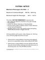


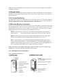
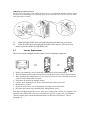
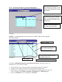


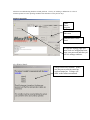

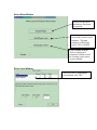

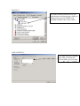
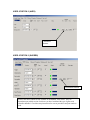


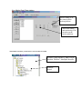


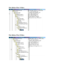


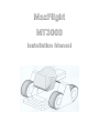

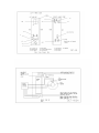


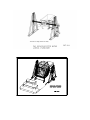
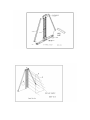

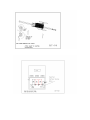
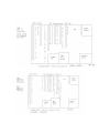

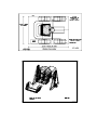
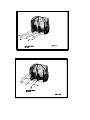
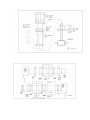
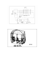
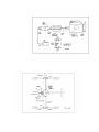
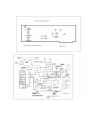


![mm [mm [1 um um [11115151116 |])|]1]](http://vs1.manualzilla.com/store/data/005839409_1-1dd2adaaab9a040f039445848c9c3135-150x150.png)