1
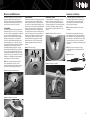
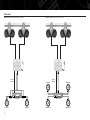
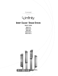
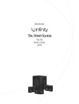
®
M A R I N E
¨
off
auto
on
6100m,
6000m,
2100m
wakeboard tower
sound system
instructions
Thank you
Infinity would like to take this opportunity to thank you for
purchasing one of our products. In order that we may better
serve you should you require warranty service, please retain
your original purchase receipt. If you would like to register your
product, please visit our Web site at www.infinitysystems.com.
INTRODUCTION
INSTALLATION WARNINGS
DESCRIPTION
CLEANING AND PRECAUTIONS
WARNING!
Loud music can cause permanent damage to your
hearing. We recommend listening to your system
at moderate volume levels while driving your
boat. Infinity accepts no liabilities for hearing loss,
bodily harm or property damage resulting from
the use or misuse of our products.
• Always wear protective eyewear when using
tools.
• The 6000m Wakeboard Tower Speakers are
constructed of weatherproof cast-polymer,
and have passed our most stringent tests to
ensure that you get only the best quality
product. The 6100m uses two active 6-1/2"
polypropylene speakers with a 1" CMMD™
tweeter. The cast-aluminum mounting
brackets are adjustable to fit almost any
commonly available tube (1-1/2" to 2-1/2")
and can be configured for surface mounting.
Although the 6000m speaker pods are waterand salt-spray-resistant, keep in mind that the
speakers are exposed and may be damaged
during washdowns. Use only a damp cloth to
wipe the speakers down. DO NOT spray water,
or any liquids, directly at the speakers. High
pressure may damage the speakers, especially
the tweeters. The 6100m and 2100m amplifiers
should be installed where they will not come in
contact with water or other liquids. The amplifier
could be damaged during washdowns.
IMPORTANT
To get the best performance from your Infinity
Marine Audio products, we strongly recommend
that installation be entrusted to a qualified
professional. Although these instructions explain
how to install the Wakeboard Tower System
in a general sense, they do not show specific
installation methods that may be required for
your particular application. If you do not have
the necessary tools or experience, do not attempt
the installation yourself. Instead, please ask your
authorized Infinity car/marine audio dealer about
professional installation.
• Turn off the audio system and other electrical
devices before you start. Disconnect the (–)
negative lead from your boat’s battery and/or
turn off the battery switch if you have a
multiple battery setup.
• Check clearances on both sides of a planned
mounting surface before drilling any holes or
installing any screws. Remember that the
screws can extend behind the surface and
could puncture the boat’s hull.
• At the installation sites, locate and make a note
of all fuel lines, steering cables, and electrical
wiring. Use extreme caution when cutting or
drilling in and around these areas.
• Before drilling or cutting holes, use a utility
knife to remove unwanted fabric or vinyl to
keep material from snagging in a drill bit or
mounting screws.
• When routing cables, keep input-signal cables
away from power cables and speaker wires.
• When making connections, make certain they
are secure and properly insulated.
2
• The 6100m Wakeboard Tower System is an
all-in-one speaker system for your boat. The
6100m includes two all-weather speaker pods
(6000m) with all of the mounting hardware,
and a dedicated 2-channel amplifier with an
integrated microphone and controls. This
system allows you to listen to music while
riding, and allows the driver to communicate
back to the rider.
• The 2100m Marine Amplifier is a stand-alone
amplifier that can be used with or without the
6100m system. This amplifier can be used to
supply power to interior speakers or additional
6000m wakeboard tower speakers.
MOUNTING THE 6000M SPEAKERS
The 6000m speakers use a unique mounting
bracket that works with various tube sizes
and flat mounting surfaces. The speakers also
incorporate a swivel feature that allows you to
easily turn them once they’re mounted.
TUBE-MOUNTING
The 6000m speakers can accommodate tower
tubes that range from 1-1/2" to 2-1/2" in diameter. The top of the mounting bracket is made with
two cutouts that allow the bracket to easily
adjust to the tower. Simply rotate the bracket
90 degrees, depending on your application.
Position the bottom bracket with the speaker
and top bracket in place on the tower. Install
the supplied 2-1/2" bolts through the top bracket
and tighten in place using a 5mm hex-key
wrench. While tightening the bolts, keep the
bottom bracket parallel with the top bracket at
all four corners of the bracket. Take care not to
overtighten the bracket. See Figure 1. Once the
speakers are in position, install the set screws in
the bottom of the bracket to keep the speakers
from twisting out of place. See Figure 2.
NOTE: There are four pre-tapped mounting
holes (1/4-20 thread) on the top of each
speaker bracket that can be used for mounting
accessories, such as lighting. See Figure 3.
CONNECTING THE SPEAKERS
SURFACE-MOUNTING
Some towers may have a flat support panel used
to mount accessories such as lighting, board
holders, radars, antennas or other accessories.
If you wish to mount the 6000m speakers to this
panel, use the 2-1/2" screws to clamp the bracket
together, as shown in Figure 3. Using the four
mounting holes in the top of the bracket, align
the speaker with holes on the mounting plate on
the tower. If there are no holes in the panel, use
the bracket as a template to mark the locations
of the four holes. Drill four new holes in the
panel. DO NOT drill through the holes in the
bracket. Insert the 1-1/4" bolts using the large
washers and tighten using a 5mm hex-key
wrench.
SWIVELING THE SPEAKERS
Located at the base of the speaker mounting
bracket is a swivel-lock pin. Pull this pin up
in order to swivel the speaker 270 degrees at
45-degree intervals. Once you have the speaker
near the position that you want, release the
pin and rotate the speaker until the pin locks
in place.
Connect the speakers to an amplifier using
the supplied speaker wires. The weatherproof
connectors allow for quick connection and
disconnection of the wires when installing
and removing the speakers.
Figure 4. Pulling the swivel-lock pin up.
Run the wires along the tube and secure in
place with plastic zip ties. If the tube has wire
holes available, run the speaker wires through
the tower tubes to the amplifier. Check to make
sure the wires will not come in contact with
sharp edges or metal that can damage the wires
over time.
NOTE: The white-striped wire is the positive
connection.
NOTE: The connectors are keyed to line up
properly. Check for proper alignment before
connecting.
Figure 3. Surface-mounting.
Figure 6. Key notch.
Figure 5. Swiveling the speaker.
Figure 1. Clamping the brackets down.
Figure 2. Installing the set screws.
3
MOUNTING THE AMPLIFIER
Mount the 6100m or 2100m amplifier in a
location that is away from direct contact with
water, whether from washing, big waves or
soggy riders.
Choose a location in the boat where the
amplifier will not be damaged by shifting cargo
or passengers. If the amplifier is going to be
under a seat, ensure that it is clear of all moving
parts and will not affect the seat adjustments.
If mounting the amplifier in an enclosed space,
make sure there is plenty of air circulation for
the amplifier to cool properly.
POWER CONNECTIONS
The 6100m/2100m amplifiers are capable of
delivering high power levels, and require a
reliable connection to the boat’s electrical
system in order to perform optimally. See
Figure 8 for terminal location. Please adhere
to the following instructions carefully:
GND TERMINAL
Connect the amplifier’s Ground (GND) terminal
directly to the boat’s negative (–) battery terminal
using a minimum of 8-gauge power wire.
+12V TERMINAL
Connect a minimum of 8-gauge power wire
directly to the boat’s positive battery terminal,
and install an appropriate fuse holder within
18" of the battery terminal. Do not install the
fuse at this time. Route the wire to the amplifier’s
location, and connect it to the amplifier’s positive
(+12V) terminal. Be sure to use appropriate
grommets whenever routing wires through
panels. Failure to adequately protect the positive
wire from potential damage may result in a fire.
When you are done routing and connecting this
wire, you may install the fuse at the battery.
CONTROLS AND SETTINGS
NOTE: When using the Hi-level inputs, connect
the REMOTE terminal to the source unit.
Setting the controls on the 6100m amplifier or
2100m amplifier.
REMOTE OUT
If using additional amplifiers and tower speakers
connect the REMOTE OUT terminal using a 1/4"
spade connection to the Remote input terminal
of the other amplifier. The REMOTE OUT works
in conjuction with the Power switch on the
microphone (please refer to page 5).
SETTING THE GAIN
1. Start with the GAIN control set to minimum
(counterclockwise) and set the music level on
the microphone to maximum (clockwise).
LINE IN
Connect to the source unit’s line-level output
using RCA cables.
LINE OUT
Can be used to pass signal from the Line In to
additional amplifiers. Also has the option to pass
paging information (refer to Page Ext switch).
SPEAKER CONNECTIONS
Refer to the application guides on the pages
that follow. Speaker connections should be
made using the supplied speaker wires. If
additional wire is necessary, use a minimum
of 16 awg. speaker wire.
Minimum speaker impedances:
6100m amplifier 4 ohms, stereo
2100m amplifer 2 ohms, stereo/4 ohms, bridged
PAGE EXT SWITCH
When set to the ON position, the Page Ext
switch will allow the PA signal to pass through
to another amplifier when using the Line Out
outputs on the 6100m amplifier. Set to OFF if
you do not want the PA signal to pass through
to another amplifier and speakers.
2. Reconnect the negative (–) lead to the boat’s
battery. Apply power to the audio system and
play a dynamic music track.
3. On the source unit, increase the volume
control to 3/4 volume. Slowly increase the
GAIN control until you hear slight distortion
in the music. Then reduce the GAIN control
slightly until distortion is no longer heard.
Figure 8. End plates.
REMOTE
OUT
6100m
R
L
HI-LEVEL INPUT CONNECTIONS
The 6100m and 2100m amplifiers are equipped
with speaker-level inputs that allow you to add
an amplifier to head units that do not have RCA
line outputs. The speaker outputs for the source
unit should be connected to the amplifier using
the supplied connector (square four-wire plug).
Remember to check for proper polarity.
Figure 7. Speaker-level connector.
NOTE: If your boat uses a multiple battery setup,
please contact the boat manufacturer or dealer
for proper connection instructions.
REMOTE TERMINAL
Connect the amplifier’s REMOTE terminal to
the source unit’s Remote Turn-On lead, using
a minimum of 18-gauge wire. If your source
unit does not have a remote turn-on connection,
connect the amplifier’s REMOTE terminal to the
boat’s accessory circuit.
4
2100m
HIGH LEVEL
INPUT
+
R
–
+
L
–
GRAY +
GRAY/BLACK –
– WHITE/BLACK
+ WHITE
L R
Speaker Wires
(spliced)
NOTE: When using the Hi-level inputs, the
Line Out on the 6100m can be used to pass a
full-range line-level signal to another amplifier.
2100m
6100M MICROPHONE
MOUNTING THE MICROPHONE CONNECTOR PLATE
Locate a suitable place for the microphone plate
to be installed. (Make sure that there are no
wires or control lines behind this surface.)
Mark the four screw locations.
Draw an “X” between the mounting screw
locations.
MICROPHONE OPERATION
MOUNTING THE MICROPHONE HOLDER
Locate a position to secure the microphone
holder and mark screw hole positions.
NOTE: This location should be within reach of the
driver but should not hinder any of the normal
operations of the boat or safety equipment
(lights, steering, throttle control, etc.).
Predrill the holes.
Using a 7/8" holesaw, drill a hole in the center of
the “X” to allow the microphone cable to be
passed through.
Pre-drill the mounting screw locations.
Route the microphone cable from the amplifier
to the plate mounting location.
Using three of the supplied screws, mount
the holder.
Align the ring on the back of the microphone
with the holder and slide in a downward motion.
The microphone will click into the holder.
Figure 10. Mounting the microphone holder.
Pass the cable through the hole and secure
to the plate using the supplied lock ring and
ring tool.
Position the assembled plate over the mounting
hole and secure, using the supplied screws.
Connect the microphone and install the
weather-resistant cover.
Figure 9. Mounting the connector plate.
POWER SWITCH
OFF – Turns the 6100 system off.
Figure 11. Microphone.
AUTO – Allows the 6100m system to operate in
conjunction with the REMOTE trigger from your
head unit.
ON – Turns the 6100m system ON; allows the PA
feature to be used without having to turn the
audio system on.
NOTE: When you’ve finished using the system,
make sure the Power switch is placed in the
AUTO or OFF position. If the system is left in the
ON position for an extended period of time, it
may deplete the battery.
CONTROLS
Music level – Adjusts the volume of the music
that is played through the 6100m system.
Page level – Adjusts the volume level of the
paging system.
OPERATIONS AND WARNINGS
To operate the microphone, push in and hold
the MIC button while speaking. Release the
button once you are finished.
Hold the microphone approximately 3– 6 inches
from your mouth. Refrain from shouting into the
microphone; this can cause distortion at higher
volumes.
If you hear feedback (squeal) while using the
Page system, move the microphone away from
your mouth and/or reduce the page level.
5
APPLICATIONS
Figure 13. 6100m System line-level connection.
Figure 12. 6100m System speaker-level connection.
Remote
Turn-On
Splices
(not supplied)
L Speaker
6
LF Speaker
Source Unit
Splices
(not supplied)
Remote
Turn-On
RF Speaker
Source Unit
R Speaker
LR Speaker
RR Speaker
APPLICATIONS
Figure 14. 6100m System with a 2100m amplifier
powering internal boat speakers.
Figure 15. 6100m System with a 2100m amplifier and 6000m speakers.
PAGE
EXT
ON
PAGE
EXT
OFF
6100m
2100m
ON
OFF
OR
6100m
2100m
Remote
Turn-On
Remote
Out
LF Speaker
Remote
Turn-On
RF Speaker
Source Unit
Source Unit
LR Speaker
NOTE: If the 6100m is turned off using the Power switch, there is
no signal pass-through on the LINE OUT connections.
RR Speaker
NOTE: Match the gain of the output of the two speaker sets so they perform at the same volume level.
7
TROUBLESHOOTING
SPECIFICATIONS
• PROBLEM:
No audio (POWER LEDs are off).
CAUSES and SOLUTIONS:
1. No voltage at Batt + or remote terminal.
– Check all power connections with a VOM.
2. Poor ground connection.
– Check fuses.
3. Microphone power switch is off.
– Check power switch on Mic.
• PROBLEM:
No audio (POWER LEDs are on).
CAUSE and SOLUTIONS:
1. No input signal or no speaker signal.
– Check all input connections from source unit.
– Check all speaker connections.
– Check fader control on head unit.
• PROBLEM:
No audio (blue LED on – red LED flashing).**
CAUSES and SOLUTIONS:
1. Over or under voltage.
– Battery voltage above 16 volts or below
10 volts. Check battery and charging system
for proper operation.
2. Shorted output.
– Check speaker connections and wires.
• PROBLEM:
No audio (blue LED off, red LED flashing).**
CAUSE and SOLUTION:
1. Thermal protection.
– Turn the system off and allow the amplifier
to cool off.
• PROBLEM:
Distorted audio (blue LED on, red LED off).
CAUSES and SOLUTIONS:
1. Gain control is set too high, or amplifier or
source unit is defective.
– Check gain setting.
– Source unit output is distorted.
2. Short circuit in speaker wires.
– Check speaker wires for shorts or grounds.
• PROBLEM:
Music lacks punch.
CAUSE and SOLUTION:
1. Speakers are not connected properly.
– Check speaker connections for proper
polarity.
** NOTE: The microphone has a blue power LED
and the amplifier has a red power LED.
Features, specifications and appearance are subject to change without notice.
Infinity Systems, 250 Crossways Park Drive, Woodbury, NY 11797 USA
516.674.4INF (4463) • FAX 516.682.3556 • www.infinitysystems.com
© 2004 Harman International Industries, Incorporated
Infinity is a registered trademark, and CMMD is a trademark, of Harman International Industries, Incorporated.
CMMD patent nos. 6,327,372 and 6,404,897.
Part No. 6100MOM6/04 • Printed 6/04
• PROBLEM:
No audio from page.
CAUSES and SOLUTIONS:
1. Microphone is not connected properly.
– Check microphone connections.
2. Page level set to minimum.
– Check level control on microphone.
• PROBLEM:
Page is distorted.
CAUSES and SOLUTIONS:
1. Page level is too high.
– Reduce page level.
2. Shouting into microphone.
– Hold microphone away from face.
• PROBLEM:
Feedback.
CAUSES and SOLUTIONS:
1. Squealing sound from the speakers when
using the Paging system.
– Reduce page level on microphone.
– Increase distance between microphone
and mouth while speaking.
6100m
• 125W x 2 ch.
• Frequency Response: 10Hz – 40kHz
• Signal-to-Noise Ratio: 91dB
• Line-Level Input Sensitivity: 250mV – 6V
• Speaker-Level Input Sensitivity: 6V – 16V
• Speakers: 11" x 18" x 14-1/2"
• Amplifier: 8-1/8" x 8" x 2-3/8"
• Microphone: 1-1/4" x 2-1/2" x 3-5/8"
• Min. Speaker Impedance: 4 ohms, stereo
6000m
• Power Handling: 150W
• Peak Power Handling: 450W
• Sensitivity: 93dB @ 2.83V
• Frequency Response: 80Hz – 20kHz
• Impedance: 4 ohms
• Polypropylene Cone
• Cast-Polymer Basket
• CMMD™ Tweeter
• Rubber Surrounds
• UV-Resistant
• Water-Resistant
• Salt-Spray-Resistant
• 11" x 18" x 14-1/2"
2100m
• 125W x 2 ch. @ 4 ohms
• 150W x 2 ch. @ 2 ohms
• 250W x 1 ch. @ 4 ohms
• Frequency Response: 10Hz – 40kHz
• Signal-to-Noise Ratio: 91dB
• Line-Level Input Sensitivity: 250mV – 6V
• Speaker-Level Input Sensitivity: 6V – 16V
• 8-1/8" x 8" x 2-3/8"
• Min. Speaker Impedance: 2 ohms, stereo
4 ohms, bridged