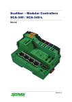
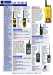
1
History of Revisions
October 1993
October 1993
December 1993
June 1994
December 1994
Original Release
Revision 01
Revision 02
Revision 03
Revision 04
Ordering Information
This manual covers software version 3.0 or greater.
To receive additional copies of this publication, order part
#560-0101-04, Apollo Handheld GPS Receiver User’s Guide.
II Morrow is a trademark of II Morrow Inc.
The Apollo logo is a registered trademark of II Morrow Inc.
No part of this document may be reproduced in any form or
by any means without the express written consent of
II Morrow Inc.
© 1994 by II Morrow Inc. All rights reserved.
Printed in the U.S.A.
II Morrow Inc.
P.O. Box 13549
Salem, OR 97309
Phone (503) 581-8101
1-800-525-6726
In Canada 1-800-654-3415
FAX (503) 364-2138
http://www.iimorrow.com
2345 Turner Road S.E.
Salem, OR 97302
U.S.A.
II MORROW
V
I
S
I
O
N
A
R
Y
T
H
I
N
K
I
N
G
T
O
D
A
Y
Important Notice
The Apollo handheld GPS receiver is intended for use as a
navigation aid. In aviation applications, the receiver should
be used to complement certified navigation instruments
already installed in the aircraft. This device is not
intended for use as a primary or sole source of
navigation information in aviation applications. Never
fly the aircraft without other available means of navigation.
For maximum safety and to minimize distraction in the
cockpit, place the receiver in an easily visible location,
within convenient view of other avionics.
This device emits a small amount of electromagnetic
energy. Do not place the receiver closer than 190mm
(approx. 7.5") to the wet compass in the cockpit.
Due to implementation of Selective Availability by the
United States Department of Defense, all GPS receivers
may suffer degradation of position accuracy by as much as
100 meters.
The following guidance has been issued by the FAA,
Seattle Aircraft Certification Office and Seattle Aircraft
Evaluation Group on December 12, 1994. It is relevant
to the use of portable GPS navigation systems in
aircraft:
The information contained in FAA Flight
Standards Notice No. 8310.171, dated October
19, 1992, is still applicable.
The use of portable GPS receivers in aircraft falls
under FAR 91.21 for Portable Electronic Devices
for operations conducted under FAR part 91
Operating Rules Only. It is the responsibility of
the aircraft operator to ensure that the device does
not interfere with other systems in the aircraft.
The GPS system must not be used for primary
navigation and can only be used for comparison
purposes during flight(s).
Official Notifications to the User
U.S.
This device complies with Part 15 of the F.C.C. Rules.
Operation is subject to the following two conditions:
(1) this device may not cause harmful interference, and
(2) this device must accept any interference received,
including interference that may cause undesired operation.
Canada
This digital apparatus does not exceed the Class B limits
for radio noise emissions from digital apparatus as set out
in the Radio Interference Regulations of the Canadian
Department of Communications.
Le présent appareil numérique n’émet pas de bruits
radioélectriques depassant les limites applicables aux
appareils numériques de classe B prescrites dans le
reglement sur le brouillage radioelectrique public par le
ministère des communications du Canada.
Germany
It is hereby certified that the Model 920 GPS handheld has
been suppressed in accordance with the provisions for the
BMPT-AmtsblVfg 243/1991. The correct operation of some
equipment (for example, test transmitters) in accordance
with the regulations may be subject to certain restrictions.
Please refer to the notes in the operating instructions.
The Bundesamt für Zulassungen in Der Telekommunikation
has been notified of the placing on the market of this
equipment and the right has been granted to test the series for
compliance with the regulations.
Hiermet wird bescheinigt, daß das Model 920 GPS handheld
in Übereinstimmung mit den Bestimmungen der
BMPT-AmtsblVfg
243/1991
funkenstört
ist.
Der
vorschriftsmäßige Betrieb mancher Geräte (z. B. Meßsender)
kann allerdings gewissen Einschränkungen unterllegen.
Beachen Sie deshalb die Hinweise in der Bedienungsanleiung.
Dem
Bundesamt
für
Zulassungen
in
Der
Telekommunikation wurde das Inverkenhrbringan dieses
Gerätes angezeigt und die Berechtigung zur Überprüfung
der Serie auf Einhaltung der Bestimmungen eingeräumt.
Table of Contents
Page
Section A - Introduction to Satellite Navigation . A-1
What is GPS? . . . . . . . . . . . . . . . . . . . . . . . . . . A-1
What Does the GPS Receiver Do?. . . . . . . . . . A-1
How Does GPS Work?. . . . . . . . . . . . . . . . . . . A-1
Section B - Getting Started . . . . . . . . . . . . . . . . . . B-1
Switching the GPS Receiver On and Off . . . . . B-1
Switching the Display Backlight On and Off. . B-2
The Function Keys . . . . . . . . . . . . . . . . . . . . . . B-2
The MENU/PWR Key. . . . . . . . . . . . . . . . . B-2
The NEW WPT Key . . . . . . . . . . . . . . . . . . B-3
The INFO Key . . . . . . . . . . . . . . . . . . . . . . . B-3
The GOTO/NRST Key . . . . . . . . . . . . . . . . B-3
The ARROW Keys . . . . . . . . . . . . . . . . . . . B-4
The ENTER Key . . . . . . . . . . . . . . . . . . . . . B-4
Calling the Navigation Screens . . . . . . . . . . . . B-4
Helpful Instructions on the Display . . . . . . . . . B-5
Entering a Seed Position. . . . . . . . . . . . . . . . . . B-6
Entering a Destination Waypoint . . . . . . . . . . . B-8
Searching for Nearest Waypoints. . . . . . . . . . . B-9
Navigating to a Destination . . . . . . . . . . . . . . B-10
The Navigation Screens . . . . . . . . . . . . . . . . . B-10
Numeric Navigation Screens . . . . . . . . . . . B-11
Moving Map Screens. . . . . . . . . . . . . . . . . B-13
i
Zooming In or Out . . . . . . . . . . . . . . . . . . . B-14
Auto Zoom. . . . . . . . . . . . . . . . . . . . . . . . . B-16
Orthographic Navigation Screen . . . . . . . . . . B-17
Other Screens . . . . . . . . . . . . . . . . . . . . . . . . . B-17
Creating Waypoints . . . . . . . . . . . . . . . . . . . . B-18
Entering Present Position as a Waypoint. . B-18
Creating User Waypoints. . . . . . . . . . . . . . B-19
Using the Navigation Simulator . . . . . . . . . . . B-20
Section C - The Waypoint Database. . . . . . . . . . . C-1
Available Waypoint Information . . . . . . . . . . . C-2
ARPT Waypoint Information . . . . . . . . . . . C-2
VOR Waypoint Information . . . . . . . . . . . . C-2
NDB Waypoint Information . . . . . . . . . . . . C-3
INT Waypoint Information . . . . . . . . . . . . . C-3
CITY Waypoint Information . . . . . . . . . . . . C-3
USER Waypoint Information . . . . . . . . . . . C-3
Viewing Waypoint Information . . . . . . . . . . . . C-4
“GOTO” Waypoint Information . . . . . . . . . C-4
Nearest Waypoint Information . . . . . . . . . . C-5
Scanning Waypoints for Information . . . . . C-6
Section D - Advanced Features . . . . . . . . . . . . . . . D-1
The Main Menu . . . . . . . . . . . . . . . . . . . . . . . . D-1
Calling the Main Menu . . . . . . . . . . . . . . . . . . D-1
Main Menu Options . . . . . . . . . . . . . . . . . . . . . D-2
Return to Nav . . . . . . . . . . . . . . . . . . . . . . . D-3
Operation Mode. . . . . . . . . . . . . . . . . . . . . . D-3
ii
Time and Place . . . . . . . . . . . . . . . . . . . . . . D-4
Screen and Beeper . . . . . . . . . . . . . . . . . . . . D-5
Map Setups . . . . . . . . . . . . . . . . . . . . . . . . . D-6
Declutter Maps . . . . . . . . . . . . . . . . . . . . . . D-7
Track Point History . . . . . . . . . . . . . . . . . . . D-8
Arrival Alerts. . . . . . . . . . . . . . . . . . . . . . . D-10
Airspace Alerts . . . . . . . . . . . . . . . . . . . . . D-10
CDI Scale. . . . . . . . . . . . . . . . . . . . . . . . . . D-12
Parallel Track. . . . . . . . . . . . . . . . . . . . . . . D-13
Magnetic Var . . . . . . . . . . . . . . . . . . . . . . . D-14
Countdown Time . . . . . . . . . . . . . . . . . . . . D-15
Display Units . . . . . . . . . . . . . . . . . . . . . . . D-15
Serial Outputs . . . . . . . . . . . . . . . . . . . . . . D-16
Battery Check . . . . . . . . . . . . . . . . . . . . . . D-18
User Waypoint Management. . . . . . . . . . . D-19
System Information . . . . . . . . . . . . . . . . . . D-21
Setting Up Multiple Leg Trips . . . . . . . . . . . . D-21
The Route Screen . . . . . . . . . . . . . . . . . . . D-21
Creating a Route . . . . . . . . . . . . . . . . . . . . D-22
Changing a Route Waypoint . . . . . . . . . . . D-23
Adding a Route Waypoint . . . . . . . . . . . . . D-24
Deleting Route Waypoints . . . . . . . . . . . . D-25
Starting a Route . . . . . . . . . . . . . . . . . . . . . D-26
Stopping or Holding a Route. . . . . . . . . . . D-26
Resuming a Route . . . . . . . . . . . . . . . . . . . D-27
Route “Direct To” . . . . . . . . . . . . . . . . . . . D-28
iii
Entering GPS Approaches . . . . . . . . . . . . . . . D-29
GPS Overlay Approaches . . . . . . . . . . . . . D-29
Approach Waypoint Identifiers . . . . . . . . . D-29
Runway Centerline Extensions . . . . . . . . . D-31
Runway Centerline Waypoint Identifiers . D-32
Inserting Approaches Into Routes . . . . . . . D-32
Checking Satellite Signal Strength. . . . . . . . . D-35
Managing Messages . . . . . . . . . . . . . . . . . . . . D-36
Airspace Alert Message. . . . . . . . . . . . . . . D-37
Arrival Alert Message . . . . . . . . . . . . . . . . D-37
Low Battery Alert Message. . . . . . . . . . . . D-38
No Position Alert Message . . . . . . . . . . . . D-38
Parallel Track Alert Message . . . . . . . . . . D-39
Course Deviation Alert Message. . . . . . . . D-39
Current Messages . . . . . . . . . . . . . . . . . . . . . . D-40
External Electrical Connections . . . . . . . . . . . D-40
Section E - Differential GPS Operation . . . . . . . . E-1
What is Differential GPS? . . . . . . . . . . . . . . . . E-1
How Does Differential GPS Work? . . . . . . . . . E-1
Using Differential GPS. . . . . . . . . . . . . . . . . . . E-2
Where is Differential GPS Data Available? . . . E-2
Section F - Care of the GPS Receiver . . . . . . . . . . F-1
Replacing the Batteries . . . . . . . . . . . . . . . . . . . F-1
Cleaning the GPS Receiver. . . . . . . . . . . . . . . . F-2
Section G - Glossary of Navigation Terms. . . . . . G-1
iv
Section H - Index . . . . . . . . . . . . . . . . . . . . . . . . . . H-1
Specifications . . . . . . . . . . . . . . . . . . . . . . Back Cover
V
Notes:
Section A - Introduction to Satellite Navigation
The Global Positioning System (GPS) is a What
constellation of 24 satellites in six orbit lanes is GPS?
10,898nm above the earth. Each satellite orbits
the earth twice in 24 hours.
The Apollo handheld GPS receiver is a
portable position sensor and computer which
receives signals from the GPS satellites to
provide highly accurate position information.
With an extensive database of waypoint
information and the ability to allow the user to
create up to 2,000 “customized” waypoints, the
Apollo handheld GPS receiver gives you the
ability to navigate to any point in the world
with unsurpassed accuracy.
What
Does the
GPS
Receiver
Do?
GPS satellites transmit complex streams of data How Does
the GPS receiver uses to find the satellite’s GPS
position, the current time, and other Work?
information. With signals from three or more
satellites, the receiver can calculate latitude and
longitude; with four or more satellites, altitude
can also be calculated. For optimal access to
satellite signals, the GPS antenna should have
an unobstructed view of the entire sky. The
internal antenna is located in the top portion of
the Apollo handheld GPS receiver.
A
1
A
2
Depending on the relative position of the
satellites to one another, their elevation above
the horizon, and other factors, the accuracy of
the position fix can change. Under ideal
conditions, the position can be accurate to
within 10 meters. In general, a GPS receiver
position fix is accurate to within 100 meters.
GPS altitude is based on a mathematical
model of the sphere of the earth. Including
intentional
degradation
introduced
by
Selective Availability, GPS altitude may differ
from barometric altitude by several hundred
feet.
Unlike land-based position sensors, a GPS
receiver can provide an accurate position fix
over land, sea, or in the air anywhere in the
world. Also, position accuracy of the GPS
receiver is unaffected by atmospheric conditions.
Intended for use in aviation, marine, and general
terrestrial applications, the Apollo handheld GPS
receiver is an advanced navigation device built
with quality and pride. We at II Morrow Inc. are
certain you will find it to be a versatile and
valuable travel companion.
Section B - Getting Started
This section explains how to get started using
the Apollo handheld GPS receiver.
Information in this section explains how to:
n
n
n
n
n
n
B
1
understand the keys on the keypad
enter a destination waypoint
navigate to a destination
save your present position in memory
create user waypoints
use the navigation simulator
The Apollo handheld GPS receiver is easy to
use. Install the batteries included or connect
the receiver to an external power source. Then,
spend a few minutes to read the instructions in
this section and you will be on your way to
navigating with precise accuracy.
To switch the
receiver on, press
the
MENU/PWR
key.
To switch the
receiver off, press
and
hold
the
MENU/PWR key.
Switching
the GPS
Receiver
On and Off
Switching
the Display
Backlight
On and Off
The Apollo handheld GPS receiver is
equipped with a display backlight, allowing
you to view the display in low light
conditions.
Press the MENU/
PWR key to access
the main menu. A
symbol in the
upper right of the
screen
indicates
battery capacity.
B
2
Press the MENU/
PWR key several
times to switch the
display backlight
from off to low
intensity, then high
intensity, then off.
The
Function
Keys
The MENU/PWR Key
Use the MENU/
PWR key to switch
the receiver on and
off, and to access
to the main menu
of
options
at
anytime.
The NEW WPT Key
Use the NEW WPT key to
create a new waypoint at
anytime.
The
created
waypoint can be the present
position or enter latitude
and longitude coordinates
to create a “customized”
user waypoint.
The INFO Key
Use the INFO key to view
information about any
waypoint in memory,
whether user created or
from the included database.
The GOTO/NRST Key
Use the GOTO/NRST key
to assign a destination
waypoint, either user
created or from the
included database. You
can also use this key to
select the nearest waypoint
as a destination.
B
3
The ARROW Keys
B
4
Use the ARROW keys to
move around the display,
select menu items, and
make changes.
The ENTER Key
Use the ENTER key to
“tell” the receiver to accept
a selection from any menu
or
to
acknowledge
messages on the display.
Calling the
Navigation
Screens
You can quickly call the navigation screens to
view navigation progress anytime. This can be
helpful if you accidentally select an option from a
menu, or if you decide to abandon making
changes.
Press the MENU/ PWR key
to access the main menu.
The “Return to Nav” option
is automatically selected.
Press the ENTER key to
return to the navigation
screens.
When selecting options from menus or
acknowledging
messages,
the
Apollo
handheld GPS receiver shows you what to do.
Helpful instructions typically appear on the
top and bottom lines of the display.
A highlighted, or
darkened word in an
instruction advises
you of which key to
press to select an
option.
An up/down or left/
right arrow symbol
may appear at the
lower right corner
of the display to
advise you that
additional options
are available by
using the ARROW
keys.
Helpful
Instructions
on the
Display
B
5
Entering a
Seed
Position
B
6
The first time the Apollo handheld GPS
receiver is switched on, it must locate
satellites in the sky from which to acquire
signals before determining a position fix. This
is a slow process, involving complex, lengthy
mathematical operations and can take 30
minutes or more to complete. To enable the
receiver to quickly locate and track available
satellites, you must enter a seed position and
the current time.
Press the MENU/
PWR key to access
the main menu.
Select the “Time and
Place” option and
press the ENTER
key.
Use the ARROW
keys to select and
change latitude and
longitude values.
Set the latitude and
longitude coordinates
near
to
your
position.
It is not necessary to enter minutes or
hundredths of a minute values.
Set the date. Use
the ARROW keys
to select and set
the current month,
day and year.
Set the time. Use
the ARROW keys
to select and set
local time.
Set the difference
between local time
and UTC time.
Deduct one hour
UTC differential for
daylight saving time.
For example, if UTC time is noon and it is
7:00 A.M. the same day in your time zone, the
UTC time differential would be +05.00.
Press the ENTER
key to enter the time
and place and return
to the main menu.
B
7
Entering a
Destination
Waypoint
B
8
Press the GOTO/
NRST key to select
a
destination
waypoint.
The
destination
waypoint screen
shows on the
display.
Use the ARROW
keys to select and
change
each
character of the
destination
waypoint identifier.
You can also select and change the type of
destination waypoint: airport, NDB, VOR,
INT, or user created.
To view information
about any waypoint,
press the INFO key.
Section C contains important details about
available waypoint information.
When the desired
waypoint shows on the
display, press the
ENTER key to set the
waypoint as the
destination.
To search for the
nearest waypoints to
your present position,
press the GOTO/
NRST key twice.
A list of the
nearest 30 waypoints
with their bearings and
distances from your
present position shows on
the display.
Use the UP or DOWN
ARROW keys to select
a waypoint in the list as
a destination.
View information about
any waypoint by
pressing the INFO key.
B
9
Searching
for Nearest
Waypoints
When the desired
waypoint is selected,
press the ENTER
key to set the
waypoint as the
destination.
B
10
Navigating
to a
Destination
Once a destination waypoint is entered, view
your navigation progress using the navigation
screens. These screens contain all the
information you need to navigate to a
destination.
The
Navigation
Screens
The navigation screens show on the display
whenever you finish using one of the function
keys (MENU/PWR, NEW WPT, INFO, or
GOTO/NRST). Three different types of
navigation screens are available:
n
n
n
numeric navigation screens
moving map navigation screens
an orthographic navigation screen
(for marine application only)
Select the navigation
screens by pressing
the UP or DOWN
ARROW keys.
Numeric Navigation Screens
The numeric navigation screens contain precise
navigation information in number form.
This is a numeric
navigation screen.
It shows:
n
n
n
n
n
n
n
the destination waypoint
distance to the destination waypoint (RNG)
bearing to the destination waypoint (BRG)
current ground speed (GS)
estimated time en route (ETE)
ground track (TRK)
course deviation left or right (indicated in
the rectangle at the bottom of the display)
B
11
B
12
This numeric screen
is similar to the
previous screen with
the
following
exceptions:
n
n
n
desired track (DTK) replaces ground
speed
estimated time of arrival (ETA) replaces
range
UTC (or LOC if local time offset is
entered), in 24 hour format, replaces
estimated time en route.
This numeric screen
shows still more
information.
Displayed information includes:
n
n
present latitude/longitude position (degrees,
minutes, and thousandths of a minute)
current GPS altitude
Moving Map Screens
One of the most attractive features of the
Apollo handheld GPS receiver is its ability to
show moving map navigation screens. The
moving map screens graphically show your
navigation progress against a map of nearest
waypoints. You can select from several
different moving map screens.
This moving map
screen
with
navigation data is
actually
two
screens in one.
Navigation data includes:
n
n
n
n
n
n
destination waypoint
bearing to the destination waypoint
distance to the destination waypoint
ground speed
ground track (TK)
course deviation left or right
B
13
This moving map
screen shows the
navigation data in
each corner.
B
14
This screen includes:
n
n
n
n
the destination waypoint (upper left
corner)
bearing to the destination waypoint
(upper right corner)
distance to the destination waypoint
(lower right corner)
map zoom scale (lower left corner)
Zooming In or Out
You can zoom in or out to enhance the view of
navigation progress on any moving map
screen. Zooming in or out changes the map
scale shown in the lower left corner of the
screen.
Zoom in or out by
using the LEFT or
RIGHT ARROW
keys.
Here are some examples of how zooming
works:
This screen shows
a 20 nautical mile
scale selection.
A distance of 20 nautical miles exists from the
airplane icon (near waypoint SLE) to the top
of the screen.
Selecting
a
smaller map scale
reveals additional
detail, such as
runways.
This can be helpful when approaching the
destination waypoint.
B
15
Auto Zoom
B
16
The auto zoom feature changes the moving
map scale automatically. While navigating,
auto zoom adjusts the map scale to zoom in
closer and closer as you approach the
destination waypoint. When traveling away
from a waypoint, auto zoom adjusts the map
scale to zoom out as the distance from the
waypoint increases.
Use the LEFT or
RIGHT ARROW
keys to select auto
zoom.
The screen shows
“Auto” for the map
scale, meaning auto
zoom is selected.
In this case, the
map scale is the
distance to the
active waypoint.
You can use the auto zoom feature with any of
the moving map screens.
When the Apollo handheld GPS receiver is set Orthographic
for use in marine applications, the Navigation
orthographic navigation screen is available. Screen
This screen shows the destination waypoint
ahead and clearly indicates course deviation
left or right.
B
17
The same navigation
information available
in the moving map
screens shows in the
box at the right side
of the screen.
Section D contains information on how to set
up the navigation screens to your preference,
and how to select operating modes for
different applications.
Other screens are available that contain Other
information important to navigation. These are: Screens
n
n
n
the GPS signal strength screen
the route screen
the current messages screen
Section D contains a description of how to use
these screens.
Creating
Waypoints
B
18
In addition to the included database of
waypoints, the Apollo handheld GPS receiver
allows you to create and store up to 2,000 of
your own waypoints. You can use your
present position as a waypoint, or create
waypoints based upon latitude and longitude
coordinates.
Entering Present Position as a Waypoint
Press the NEW
WPT key. Then,
press the ENTER
key. The position is
entered as waypoint
#0001.
Up to 1,999 more waypoints can be created this
way while navigating. Each entry is automatically
incremented. After repeating this process, the
next entry would be waypoint #0002.
To quickly enter a new waypoint as a
destination, press these keys: (1) NEW WPT,
(2) GOTO/NRST, and (3) ENTER.
Creating User Waypoints
Press the NEW
WPT key.
The
waypoint
creating
screen
shows on the
display.
Use the ARROW
keys to select and
change
the
waypoint
identifier and/or
position.
Press the ENTER
key to save the
waypoint
information.
B
19
Using the
Navigation
Simulator
B
20
Once you have become comfortable with basic
operation of the receiver, you may wish to use
the built in navigation simulator to practice
navigating without actually traveling. As you
practice, you may wish to refer to Section D
which contains information about additional
features of the Apollo handheld GPS receiver.
Try these features as you use the simulator to
become familiar with them. In this way, you
will gain maximum benefit from this powerful
navigation device.
Press the MENU/
PWR key to call
the main menu.
Use the UP and
DOWN ARROW
keys to select
“Operation Mode”
and press the
ENTER key.
Use the LEFT or
RIGHT ARROW
keys to select
“Simulator.” Then
press the ENTER
key.
You can select the
speed of simulated
travel from 0 to
900 units.
All receiver options are available while using
the simulator.
When you finish using the simulator, change
the operation mode to a different setting to use
the receiver for actual navigation. Or, simply
switch the receiver off. The previously used
non-simulator mode will be active when you
next switch the receiver on.
B
21
Section D contains information about other
available operation modes.
B
22
Section C - The Waypoint Database
To aid the navigator, extensive databases of
information are available for the Apollo
handheld GPS receiver.
n
Aviation databases provide waypoint
information for airports (ARPT),
non-directional beacons (NDB), very
high frequency omnirange (VOR), GPS
overlay approaches, and enroute and
terminal intersections (INT).
n
The city database (CITY) provides
waypoint information for cities and
townships.
n
The user database (USER) provides
access to information for all user created
waypoints.
C
1
Available
Waypoint
Information
The following information is available for
each waypoint category.
ARPT Waypoint Information
n
n
n
n
C
2
n
n
n
n
n
n
geographic location
airport type
airport elevation
fuel availability by type
runway length(s) and surface type
radio communication frequencies (an
asterisk at the frequency indicates
part-time availability)
latitude/longitude coordinates
navigation beacon light
IFR capability
landing fee
VOR Waypoint Information
n
n
n
n
n
n
n
n
geographic location
operating frequency
distance from present position
bearing from present position
latitude/longitude coordinates
DME available
class (high/low/terminal)
weather broadcasts
NDB Waypoint Information
n
n
n
n
n
n
n
geographic location
operating frequency
distance from present position
bearing from present position
latitude/longitude coordinates
DME available
class (high/low/terminal)
INT Waypoint Information
n
n
n
n
country
distance from present position
bearing from present position
latitude/longitude coordinates
CITY Waypoint Information
n
n
n
n
n
geographic location
population
distance from present position
bearing from present position
latitude/longitude coordinates
USER Waypoint Information
n
n
n
bearing from present position
distance from present position
latitude/longitude coordinates
C
3
Viewing
Waypoint
Information
Waypoint information is always available
when you press the INFO key. Unless you
choose differently, information shows for the
current destination waypoint. However, you
can easily view information for other
waypoints. Follow these examples.
“GOTO” Waypoint Information
C
4
You can view information about a waypoint
before selecting it as a destination.
Press the GOTO/
NRST key. Then,
use the ARROW
keys to select the
waypoint
identifier
and
category.
Press the INFO key
to view waypoint
information.
Nearest Waypoint Information
You can view information about the nearest
waypoints.
Press the GOTO/
NRST key twice
to search for the
nearest waypoints.
Use the UP or
DOWN ARROW
keys to select a
waypoint.
Press the INFO
key
to
view
waypoint
information.
It is not necessary to enter the waypoint as a
destination to view information.
C
5
Scanning Waypoints for Information
While navigating using the moving map
screens, you can easily scan nearby waypoints
for information.
Press the ENTER key repeatedly to select any
waypoint on the screen.
C
6
The
selected
waypoint
identifier shows as
highlighted,
or
darkened.
Press the INFO key
to
view
information about
the
selected
waypoint.
Section D contains information on how to set
up the moving map screens and nearest
waypoint search list to your preference. The
way these are set up affects which waypoints
show on the moving maps or in the waypoint
search list.
Section D - Advanced Features
This section explains how to use advanced
features of the Apollo handheld GPS receiver
to enable you to gain maximum benefit of its
powerful capabilities. Information in this
section explains how to:
enter multiple leg trips in memory
check GPS satellite signal strength
n customize moving map displays
n manage user created waypoints
D
n manage messages
n use the countdown timer
1
n setup multiple leg trips
n customize display of navigation information
n setup the receiver for different types of
use
Many features of the Apollo handheld GPS The
receiver are accessible from the main menu. Main Menu
Options on the main menu allow you to set up
the receiver to your preference and manage the
information it gives you.
n
n
Call the main menu
for display at any
time by pressing
the MENU/ PWR
key.
Calling the
Main Menu
Navigation is not interrupted while accessing
menu options.
Use the UP or DOWN ARROW keys to select
menu options. The arrow marker shows the
currently selected option.
Main Menu
Options
Available options on the main menu are:
n
n
n
D
2
n
n
n
n
n
n
n
n
n
n
n
n
n
n
n
return to navigation screen
operation mode
time and place
screen and beeper
map setups
declutter maps
track point history
arrival alerts
airspace alerts
CDI scale
parallel track
magnetic variation
countdown timer
display units
serial outputs
battery check
user waypoint management
system information
A description of each option follows.
Return to Nav
The "Return to Nav" option is automatically
selected when the main menu is called,
allowing you to conveniently return to the
navigation screen previously in use. Select this
option when you finish using the main menu,
or anytime you wish to return to the
navigation screen in use before the main menu
was called.
D
3
Operation Mode
Select your intended type of use for the
receiver with this option. Position accuracy is
optimized for each operating mode. Available
operation modes are:
n aviation
n hiking
n land mobile
n marine
n survey
n simulator
This option also allows you to select the map
datum for each mode except simulator.
WGS 1984 is the most recent datum and
should normally be used unless you plan to
navigate with a chart that was created using an
older datum. In this case, you may wish to
select the datum used to create the chart.
Change
Settings
D
4
The simulator mode allows you to practice
navigating without actually traveling. All
options are available in simulator mode. You
can select the speed of simulated travel from 0
to 900 units. After simulator use, the receiver
will return to the previously used nonsimulator operation mode the next time you
switch the receiver on.
Time and Place
Use this option to enter your present position
and set UTC and local times as Section B
describes in “Entering a Seed Position.” It is
necessary to enter the time and place the first
time the receiver is switched on. It is also
necessary to enter this information if the
receiver is switched off and moved a distance
of several hundred miles or more.
Time information is lost in about 10 minutes if
power is removed from the receiver. Replace
weak batteries promptly or connect the
receiver to external power to avoid losing and
having to re-enter this information.
Screen and Beeper
This option controls operation of the built-in
beeper and display backlight, and allows you
to adjust display contrast.
Change
Settings
The beeper setting controls when the beeper
sounds: MSG -beeps for messages, KEY beeps each time you press a key, MSG &
KEY - beeps for both, and OFF - beeper does
not sound.
Use the backlight to view the display in low
light or darkness. You can select low or high
intensity backlight settings from this screen.
(You may also change the backlight setting by
pressing the MENU/PWR key several times.
See page B-2.)
D
5
The backlight requires extra power to operate.
To extend battery life, keep the display
backlight off or use the “lo” setting.
D
6
The contrast setting changes the contrast of
the display. Use the left and right arrow keys
to adjust the contrast. The best setting is
determined by available light conditions and
the visual angle at which you view the display
when you use the receiver. (You may also
change the contrast by pressing the
MENU/PWR key and the right or left arrow.
See the inside front cover.)
Map Setups
This option controls what and how
information shows on the moving map
navigation screens.
Change
Settings
You can select whether or not to show a route
path or airspaces in the vicinity. You can also
select orientation of the moving maps, with
the top of the screen representing current
track, desired track, or true north.
This
example
shows a moving
map screen with
the route path and
airspaces selected
to show.
Zoomed in on the
moving map, the
route
function
clearly
shows
course deviation.
Personal preference dictates how to use these
options to their best advantage.
Declutter Maps
This option controls which waypoints show on
the moving map navigation screens. A type of
waypoint set to “On” will show on the moving
map screens. Other waypoints will not show.
You can also select whether or not waypoint
identifiers show on the screens. With
identifiers not selected to show, small boxes
represent waypoints. The destination waypoint
always shows with identifier, regardless of
this setting.
D
7
Change
Settings
Whether or not the identifiers show, you can
scan waypoints on the moving map screens for
information as Section C describes.
D
8
This option also controls which types of
waypoints appear in the list after a search for
nearest waypoints. These settings are
important! Only the types of waypoints you
choose will show in the nearest waypoint list.
Track Point History
This option allows you to store a record of
navigation progress. The stored record is a
series of track points, each containing your
position at the time the point was stored. You
can choose whether or not to store track
points, how often to store them, and manage
the storage process using this option.
Each stored track point consumes space in
memory. You can store up to 2000 track
points.
Change
Settings
When track history is “on,” points are stored
in memory.
Your track history
is displayed on the
moving
map
screens as a series
of dots indicating
the stored point.
You can select the track point storage strategy.
Select “forever” to continuously store points,
starting over when memory becomes full, or
select “Until Full” and stop storing points
when memory becomes full.
You can also control the storage interval for
track points. Saving points by “distance”
allows you to select a distance interval at
which each track point is stored. Similarly,
saving points by “time” allows you to select a
time interval for storage of each track point.
D
9
The screen shows you how much memory
space is used for track point storage. If you
wish to empty the memory of track points,
select “clear?” and choose “yes.”
Arrival Alerts
This option controls whether or not and when
the receiver should alert you of arrival at a
destination waypoint.
D
10
If you choose arrival alert messages, the
beeper will sound and a message will show on
the display advising you of arrival at a
destination waypoint. You can set the radius
distance around the destination waypoint at
which the receiver alerts you.
Change
Settings
Airspace Alerts
Use this option to control if and when the
receiver should alert you when approaching a
class B TCA, class C ARSA, or special use
airspace.
Change
Settings
If you choose airspace alerts, you can select:
n
n
n
n
whether or not alert messages are issued
the type of message - Class B and C,
Special Use (Restricted, Danger), or All
the radius distance from the airspace
border at which to be alerted
the travel time (based upon current track
and speed) from the airspace border at
which to be alerted
Special Note: The type of message selected
here also controls the type of airspaces
displayed on the map screens and on the
message page.
If the receiver is computing a 3D position fix,
the GPS altitude will be used to avoid an alert
message when above or below the airspace
ceiling or floor. To compensate for the
inaccuracies of GPS altitude, a buffer of 1,000
feet is added to the ceiling and subtracted from
the floor. For example, if the published ceiling
D
11
of an airspace you are flying over is 4,000
feet, an airspace message (if selected) occurs
when the GPS altitude is at or below 5,000
feet.
CDI Scale
This option controls operation of the course
deviation alert and allows you to set the CDI
scale units to your preference.
D
12
You can select the CDI scale maximum course
deviation left or right.
The “Alert Message” controls whether or not the
receiver will alert you with the beeper and a
message on the display indicating a course deviation
left or right in excess of the value on the scale.
Parallel Track
With this option, you can set a parallel track
course to a destination. Useful in aviation
applications where busy air corridors may
dictate a parallel track, this option sets the
receiver to navigate a course with a selectable
course deviation distance left or right.
You can select whether or not the receiver will
alert you with the beeper and a message on the
display indicating that this option is in use and
reminding you of the course deviation.
The left or right offset distance you select
represents CDI mid-scale when “Parallel
Track On” is set to “Yes.”
D
13
Magnetic Variation
This option allows you to override automatic
magnetic variation and manually enter a
variation value. This is normally not required
for navigation anywhere in the world except
near the poles, where magnetic variation is the
greatest.
D
14
If manual entry of magnetic variation is
necessary, obtain the correct value from a
reliable chart or other source. Select “Manual”
and enter the variation value east or west.
To disable magnetic variation, select “True.”
All course headings will show referenced to
true north.
Countdown Time
The Apollo handheld GPS receiver includes a
countdown timer. Use this option to enter a
time of up to 60 minutes. After starting the
timer, the receiver will sound the beeper and
show a message on the display when the
entered time has elapsed.
D
15
Display Units
This option allows you to change the way
navigation units of measure show on the display.
You can select the units shown for each
navigation parameter:
n
n
n
distance: nm/kts; sm/mph; km/kph
altitude: feet; meters
LAT/LON: d-m.mmm; d-m-S. (where
d=degrees, m=minutes, and s=seconds
of latitude or longitude)
Serial Outputs
D
16
The Apollo handheld GPS receiver is
equipped with a serial data port for
communication with external serial devices.
This option controls the outbound data
function of the port. Using this option with an
appropriate cable connection, you can:
n
n
n
send serial data to an external moving
map display
send serial data matching the NMEA
formats to any serial device capable of
accepting it
disable the serial data port
Before attempting to send serial data to an
external device, use the optional serial data
cable to connect the receiver to the desired
device. The cable is equipped with a standard
DB9 connector to fit most device serial ports.
If the device has a serial port with a different
connector, you need to purchase the correct
connector and attach it to the cable. See
“Making External Connections” at the back of
this section for information on properly
connecting the serial cable.
Use this option to select:
n
n
n
n
"None" - disable the serial port
“NMEA 0183 v1.50" - output NMEA
sentences GPBWC, GPGLL, GPRMB,
GPRMC, GPR00, GPWPL, GPXTE
“NMEA 0183 v2.00" - output NMEA
sentences GPBWC, GPGLL, GPRMB,
GPRMC, GPRTE, GPWPL, GPXTE
“Moving Map” - output moving map
data using Apollo NMC2001 format
D
17
Battery Check
This option provides a graphic indication of
battery condition on a scale from “Low” to
“Full.” The combined voltage of the six AA
batteries is indicated at the bottom center of
the screen. Also, a small battery symbol is
shown at the top of the main menu indicating
the battery capacity.
D
18
For
satisfactory
receiver operation,
battery
voltage
should be between
6 and 9 volts.
You will receive a warning message on the
display if battery voltage falls below 6 volts.
After the warning message shows on the
display, the receiver will continue to operate
for 20 to 30 minutes. Switch the display
backlight off to conserve power. Replace the
batteries promptly to avoid loss of time, user
waypoints, routes, and system setup
information stored in memory.
Do not allow low or discharged batteries to
remain installed in the receiver as leakage
could damage internal components.
User Waypoint Management
This option allows you to manage the database
of user waypoints. You can edit or delete
waypoints as your area of travel or other
requirements change.
It is important to manage user waypoints
wisely. With the capacity to store up to 2,000
user waypoints in memory, the Apollo
handheld GPS receiver can retain an immense
amount of information. When you edit, use
intuitive identifiers for waypoints you have
created. This will help you find waypoints
more easily when you need to navigate to
them.
Select “User Wpt Mgmt” from the main menu.
Use the LEFT or RIGHT ARROW keys to
select “Edit” or “Del.”
Select “Edit” and press the ENTER key to edit
existing waypoints.
Use the ARROW keys to select and change
the waypoint identifier and/or position.
D
19
Edit the waypoint
information
as
required.
Press the ENTER key to save the waypoint
information.
Select “Del” to delete a waypoint from
memory. Use the UP or DOWN ARROW
keys to select the waypoint to delete.
D
20
Press the ENTER key to delete the waypoint.
When you have
finished using this
option,
select
“Quit.”
Press the ENTER key to return to the main
menu.
System Information
This option shows the current operating software
version number and indicates the waypoint
database region, date, and version number.
No settings can be
changed.
The Apollo handheld GPS receiver has the Setting Up
ability to store up to 20 reversible trip plans or Multiple
“routes” in memory. Each route can consist of Leg Trips D
21
up to 30 waypoints, either user created or from
the built in database.
After routes are created, any route can be
called from memory for navigation. While
navigating a route, the destination waypoint
updates as you arrive at each route waypoint.
The Route Screen
Select the route
screen from any
navigation
screen
using the UP or
DOWN ARROW
keys.
The route screen shows the status and up to
the first four waypoints of each route, as well
as the desired track and distance between
consecutive waypoints. With “NXT RTE”
highlighted, use the ENTER key to view each
route. Routes not in use are “Off.”
Creating a Route
Select “Edit” from the route menu to begin
creating route 01. Then, select “Ins” to insert
waypoints into the route.
D
22
Insert waypoints along the route as you plan
the trip. Begin with the waypoint of origin and
work toward the destination waypoint. If you
desire, you can later change, add, or delete
route waypoints.
Use the ARROW
keys to select the
first waypoint to
insert. Then, press
the ENTER key.
Repeat
this
process to add
more waypoints to
the route.
As you add waypoints, the route screen shows
the bearing to each waypoint and the distance
between them.
When you finish
inserting waypoints
into the route, select
“Done” and press
the ENTER key to
save the route in
memory.
Changing a Route Waypoint
You may change any waypoint along a route.
Select the route to change from the route
menu. Then, select “Edit” as if creating a
route.
Select a waypoint to change.
When the marker
arrow points to the
desired waypoint,
select “CHG” to
change it.
Make changes to the waypoints in the route as
desired. When changes are complete, select
“Done” to enter the changes into memory.
D
23
Adding a Route Waypoint
You may add waypoints to any route. Add
waypoints to a route by inserting them into the
route.
Select the route from the route menu into
which you wish to insert waypoints. Then,
select “Edit” as if creating a route.
D
24
Use the UP or
DOWN ARROW
keys to move the
marker arrow to
the
waypoint
before which the
inserted waypoint
should be placed.
Select “Ins” to
insert the waypoint
into the route.
When desired waypoints are inserted into the
route, select “Done” and press the ENTER key to
enter the inserted route waypoints into memory.
Deleting Route Waypoints
To delete waypoints from a route, select the
route from the route menu from which you
wish to delete waypoints. Then, select “Edit”
as if creating a route.
Use the UP or DOWN ARROW keys to move
the marker arrow to the waypoint you wish to
delete.
Select “Del” to
delete the waypoint
from the route.
When desired waypoints are deleted from the
route, select “Done” and press the ENTER key
to remove the deleted route waypoints from
memory.
Deleting waypoints from routes will not
remove them from the waypoint database.
D
25
Starting a Route
When you are ready to navigate a route, it
must be started. Only one route may be started
at any time.
Select the route you wish to start from the
route menu. Select “Start” to start the route.
D
26
You may choose to
navigate the route
in either direction.
Select “Normal” to navigate the route the way
it was created, or select “Reverse” to navigate
the route from the destination waypoint to the
point of origin. After a route is started, (route
“On”) you can view other routes or edit them.
From the route screen, you can quickly return
to the active route by pressing and holding the
ENTER key.
Stopping or Holding a Route
A route on “hold” can be resumed from a
waypoint along the route, whereas a stopped
route must be restarted from the waypoint of
origin.
“Holding” a route leaves the route active, but
stops destination waypoint updating.
Stop or hold the active route by selecting it
from the route menu. Press and hold the
ENTER key to quickly select the active route.
Select “Stop” to
stop or hold the
route.
D
27
Select whether to
“Stop” or “Hold”
the route.
Resuming a Route
Select “Resume”
to resume a route
on hold.
Route “Direct To”
During navigation of a route, you may wish to
bypass one or more waypoints and proceed
directly to a destination waypoint. The route
“Direct To” option allows you to do this.
Select the active route from the route menu.
Then, select “Edit” as if creating a route.
D
28
Use the UP or DOWN ARROW keys to move
the marker arrow to the waypoint to which
you wish to navigate. Then, press the
GOTO/NRST key to enter the waypoint as the
destination.
The route screen
shows
“direct”
status
to
the
waypoint.
You can now navigate directly to the desired
destination waypoint.
GPS Approaches and Extended Runway Entering
Centerlines are available with software GPS
version 3.0 or greater. This feature allows Approaches
pilots to select an approach and automatically
insert approach waypoints into the route.
GPS Overlay Approaches
Software version 3.0 or greater includes all
published GPS overlay approaches in the U.S.
and Canada. These approaches are designed to
fit over existing NDB and VOR non-precision
approaches and allow you to monitor your
progress while flying a non-precision
approach using your approved IFR equipment.
The GPS overlay approaches MUST NOT be
flown using the Apollo handheld GPS alone.
You MUST use your IFR approved sensors
(NDB or VOR) and charts to fly the approach.
Approach Waypoint Identifiers
The approaches use published waypoints if
available, but when published waypoints are
not available, special waypoints and identifiers
are created. These created names include a
two character prefix usually followed by the
runway number (e.g., CF23L). If the approach
does not apply to a particular runway, then the
D
29
course to the way point is used (e.g., FF323).
These are also the same identifiers that appear
on approach charts modified for GPS overlay
approach use.
Each GPS overlay approach consists of two or
more waypoints. These waypoints are:
n
n
D
30
n
n
CF*** - final approach course fix
(e.g., CF17 or CF02L; about half of the
approaches have this waypoint)
FF*** - final approach fix
(e.g., FF22 or FF183; this waypoint is
always in the approach)
MA*** - missed approach point not at a
runway end (e.g., MA12 or MA21R)
RW*** - missed approach point at a
runway end (e.g., RW23L or RW 02)
A missed approach waypoint, either MA***
or RW***, is always in the approach.
NOT included in the overlay approaches are:
n initial approach fixes (may be inserted
manually)
n procedure turns or holding points
n altitude step down fixes
n missed approach holding point (may be
inserted manually)
Runway Centerline Extensions
The Apollo handheld GPS receiver includes
an automatic procedure to insert the runway
end point and a point four nautical miles out
on the runway centerline extension into any
route. These two points can be used to line up
the airplane with the runway centerline and
give distance information to the runway end.
These are NOT published approaches and do
not take into consideration any terrain or
obstacle clearance. These extensions are
provided for many runways around the world.
RW 31
4 nm
EX 31
D
31
Runway Centerline Waypoint Identifiers
Each runway centerline extension consists of
two waypoints. These waypoints are:
n
n
D
32
EX*** - extended runway centerline
waypoint four miles from the runway
end (e.g., EX04 or EX21L)
RW*** - missed approach point at a
runway end (e.g., RW23L or RW 02)
A RW*** waypoint may appear in either a
published GPS overlay approach or a runway
centerline extension.
Inserting Approaches Into Routes
To insert a GPS overlay approach or a runway
extended centerline into a route, use the
following procedure:
In the NAV mode, go to the Route page (use
the UP and DOWN ARROW keys). Press
ENTER until the desired route is displayed.
Press the RIGHT
ARROW key to
highlight EDIT,
then
press
ENTER.
The destination airport must be the last
waypoint in the route.
Press the DOWN
ARROW key until
the arrow cursor is
at the blank line
past the airport.
Press the RIGHT
ARROW key to
highlight
APPROACH, then
press ENTER.
Press the UP or DOWN ARROW keys to
select the approach. The waypoints to be
inserted are displayed at the bottom. For
runway centerline extensions, the approach
identifier is EXT (e.g. EXT RWY 16). These
appear after any overlay approaches.
D
33
Press ENTER to
insert
the
waypoints.
The destination airport is deleted and the
approach waypoints take its place. Now you
can delete any unwanted waypoints, or add
waypoints such as an Initial Approach Fix.
D
34
With
DONE
highlighted, press
ENTER and then
you can start the
route.
If you want to see routelines on the map, make
sure the Route Path is turned on in the Map
Setups under the Main Menu. After the
approach is completed, the added waypoints
can be deleted from the route and the airport
inserted back into the route.
The satellite signal strength screen shows
information about signals being received from
the GPS satellites. Information shown on the
screen includes:
n
n
n
n
n
the number of satellite signals
currently being received
the number of the satellite
transmitting each received signal
the strength of each received signal
whether or not the receiver is able
to calculate a 3D position
the azimuth and elevation angle of
each satellite from which a signal is
being received
Access the signal strength screen from any
navigation screen by pressing the UP or
DOWN ARROW keys.
This
example
shows information
about the signal
received
from
satellite 6.
The screen shows that six satellite signals are
being received. Hence, a 3D position fix is
currently being calculated by the receiver.
Checking
Satellite
Signal
Strength
D
35
The screen also shows that the signal from satellite 6 is the
weakest received. The satellite is currently located at an
elevation of 41° from a horizon azimuth of 341° and is
being tracked by the receiver.
Use the LEFT or RIGHT ARROW keys to check
signal strengths from other received satellites.
Important: When signals from fewer than
four satellites are being received, a 3D position
fix is not possible. GPS altitude cannot be
accurately calculated by the receiver.
D
36 Managing
Messages
The Apollo handheld GPS receiver helps you
navigate by informing you of important events.
These events are announced by alert messages
which show on the display anytime the receiver is
operating. An audible beep sounds and continues
until you press the ENTER key to acknowledge
the alert message.
Alert messages may alert you of:
n airspace penetration
n arrival at the destination
n excessive course deviation
n low battery power
n parallel track navigation
n loss of position fix
n expiration of countdown timer
Airspace Alert Message
The airspace alert
message shows on
the display when
you approach or
penetrate
an
airspace.
To disable airspace alert messages, use the
Airspace Alert option in the Main Menu.
Arrival Alert Message
The arrival alert
message shows on
the display when
you are within the
arrival radius of
the
destination
waypoint.
To disable arrival alert messages, use the
Arrival Alert option in the Main Menu.
D
37
Low Battery Alert Message
The low battery
alert
message
shows
on
the
display
when
battery voltage falls
below 6 volts.
The low battery alert message cannot be
disabled.
D
38
No Position Alert Message
The no position
alert
message
shows
on
the
display
if
the
position fix is lost
or
cannot
be
calculated for any
reason.
The no position alert message cannot be
disabled.
Parallel Track Alert Message
The parallel track
alert
message
shows
on
the
display to remind
you that the parallel
track option is
enabled.
To disable the parallel track alert message, use
the Parallel Track option in the Main Menu.
Course Deviation Alert Message
The
course
deviation
alert
message shows on
the display when
you exceed the
deviation distance
on the CDI scale.
To disable the course deviation alert message,
use the CDI Scale option in the Main Menu.
D
39
Current
Messages
D
40
External
Electrical
Connections
The current messages screen shows alert
messages that remain valid after being
acknowledged. You can review these
messages from any navigation screen by
pressing the UP or DOWN ARROW keys to
display the current messages screen. To view
all messages, press the ENTER key. The
current messages screen also shows the
nearest airspaces (up to five) as you press the
ENTER key. These airspaces are not shown in
any particular order.
This
course
deviation
alert
message shows an
updated deviation
distance.
The Apollo handheld GPS receiver is
equipped with electrical connectors on the
back of the case, allowing you to connect an
external power source, a serial data cable,
and/or an external GPS antenna.
External Power Serial Data
Connection
Port
External GPS
Antenna
Back of Case
To connect the unit to an external power
source, plug the included power cable into the
connector labeled “Power.” Connect the cable
to a 6VDC to 32VDC power source. Note that
the unit will use external power if the voltage
from the external source is higher than the
internal battery voltage.
6VDC to
Ground 32VDC
Electrical Connector
D
41
To connect the unit to an external serial
device, use the optional serial data cable.
Make connections as shown.
Serial Data
Differential
GPS Serial Data Output
(Blue)
Input (Green)
Ground
(Black w/Shield)
Serial Data
Input
(Red)
Serial Data Port
D
42
Section E - Differential GPS Operation
Differential GPS, or DGPS, is a method by What is
which the inherent degree of error in a GPS Differential
position fix may be greatly reduced. DGPS is GPS?
used in marine applications only. Developed
largely by the United States Coast Guard and
scheduled for completion in 1996, DGPS
helps to overcome intentional position fix
inaccuracies
introduced
by
Selective
Availability. Using DGPS, the navigational
accuracy of a GPS receiver can be increased
from approximately 100 meters to as little as
10 meters. The Apollo handheld GPS receiver
has the capability to operate using DGPS.
DGPS relies on reference stations operated by
the Coast Guard. Each reference station serves
GPS users in a particular area and contains
highly accurate and sophisticated equipment
to calculate and measure the navigational error
in received GPS signals. Navigational error is
determined by comparing the known location
of the reference station with the calculated
location using uncorrected GPS data. Once the
error is known and measured, correctional
data is made available to GPS users to
increase the navigational accuracy of their
receivers.
E
How Does
Differential 1
GPS
Work?
Using
Differential
GPS
In order to use DGPS, you must purchase a
marine DGPS receiver capable of transmitting
RTCM-104 differential GPS data at 9600 bits
per second. The data should conform to RS-232
specifications. Use the optional serial data cable
connected to the serial data port on the back of
the Apollo handheld GPS receiver for the
purpose of transferring this information. Make
connections as Section D describes. Follow
instructions provided with the DGPS receiver.
Once the DGPS data is transferred to the
handheld GPS receiver, position accuracy will
automatically be improved.
Where is
E Differential
GPS Data
2
Available?
Contact the United States Coast Guard for
information on location of reference stations.
The DGPS system is not scheduled for
completion until 1996, so DGPS may not yet
be available in your area.
For more information on DGPS, refer to
RTCM Paper #134-89/SC 104-68, RTCM
Recommended Standards for Differential
Navstar GPS Service available from the Radio
Technical Commission for Maritime Services,
PO Box 19087, Washington, D.C. 20036.
You may also contact the nearest office of the
United States Coast Guard.
Section F - Care of the GPS Receiver
Very little effort is required to care for the
Apollo handheld GPS receiver. Its rugged
construction and quality design will yield
years of trouble-free use.
Treat the receiver as you would any piece of
electronic equipment. Avoid exposing the
receiver to temperature extremes. High
temperatures
can
damage
internal
components. Do not store or operate the
receiver in below freezing temperatures.
Although the receiver is housed in a water
resistant case, avoid submersing the unit in
water. Also avoid subjecting the receiver to
severe shock, as internal damage could occur.
When not connected to an external power Replacing
F
source, the receiver is powered by six AA the
batteries. Replace the batteries by removing Batteries 1
the battery compartment cover located on the
rear side of the receiver. Observe polarity
markings inside the compartment when
replacing batteries.
Avoid leaving weak or discharged batteries
installed in the receiver as leakage could
damage internal components.
Battery
Compartment
1 2 3 4 5
6
For the best service life, use nickel cadmium
rechargeable or alkaline batteries in the
receiver.
Cleaning
the GPS
Receiver
F
2
Use a soft cloth and a mild soap solution to
clean the case exterior if it should become
soiled. Dry with a soft cloth. Avoid use of
harsh solvents or abrasive cleaners. Also avoid
excessive pressure when cleaning the display.
Section G - Glossary of Terms Used in this Guide
ALT (GPS Altitude): Altitude, as calculated by the
GPS receiver, based upon a mathematical model of the
earth’s surface curvature. A substantial difference
between this altitude value and altitude referenced to sea
level may exist.
ATIS (Automatic Terminal Information Service):
Recorded information about weather and other
conditions at an airport, periodically updated when
conditions change.
ARSA: Airport Radar Service Area
Azimuth: Bearing, as measured clockwise from true or
magnetic north.
BRG (Bearing): The direction to any point, usually
measured in 360 degrees relative to true or magnetic
north.
Constellation: A group of fixed stars or objects, such as
GPS satellites, in the heavens.
Coordinates: Latitudes and longitudes determining a
given geographical point on the surface of the earth.
G
1
Course: The planned direction of travel in a horizontal
plane.
Course Deviation: A measurement of distance left or
right from the desired course of travel.
CDI (Course Deviation Indicator): A graphic indicator
of course deviation typically shown as a graduated
horizontal bar with an icon indicating the deviation
distance left or right of course.
CTAF: Common Traffic Advisory Frequency
Database: A collection of data structured in such a way
as to allow quick and convenient access to any particular
record or records. The Apollo handheld GPS receiver
contains a built in database of waypoints and waypoint
information to which the user may add waypoints.
Degree: 1/360th of a circle.
G
2
Distance: A measure of interval in space or time. Also
referred to as range.
DME: Distance Measuring Equipment
Drift: Displacement from the intended course of travel.
DTK (Desired Track): The desired course of
navigation between a point of origin and a destination
waypoint.
Elevation: The altitude above ground.
Fix: A geographical location determined by either visual
reference or by electronic navigation aids.
GPS (Global Positioning System): Also known as
NAVSTAR. A constellation of satellites launched by the
U.S. Department of Defense into six orbit lanes (four
satellites per plane) at an altitude of 10,898nm above the
earth. The GPS constellation currently consists of 25
orbiting satellites.
GPD Overlay Approach: A non-precision approach
(such as a VOR or NDB approach) that has been
approved for use with an IFR approved GPS.
GRND (Ground): Ground communication frequency
GS (Ground Speed): Speed of travel across the ground.
In aviation, the relation between ground speed and air G
3
speed is affected by the prevailing winds.
Icon: A symbol shown on the display depicting present
position. The icon may be an airplane, boat, land
vehicle, a human stick figure, or an “X” depending on
the selected operation mode.
Identifier: A name, typically abbreviated, assigned to a
waypoint. The identifier may consist of numbers and
alpha characters, up to six in length. For example, the
airport identifier for Los Angeles International Airport is
LAX.
IFR: Instrument Flight Rules
INT (Intersection): A point defined by any
combination of courses, radials, or bearings of two or
more navigational aids.
Kt (Knot): A unit of speed equal to one nautical mile
per hour.
LAT (Latitude): Any line circling the earth parallel to
the equator, measured in degrees, minutes, and seconds
north and south of the equator.
G
4
LON (Longitude): Any line from the north to the south
pole, measured in degrees, minutes, and seconds of a
circle, east or west of the Prime Meridian, which runs
approximately through Greenwich, England.
Magnetic North: The region, some distance from the
geographic north pole where the earth’s magnetic lines
concentrate. A magnetic compass points to the magnetic
north.
Mag Var (Magnetic Variation): The angle between the
magnetic and true north. It differs at various points on
the earth due to local magnetic disturbances. It is shown
on charts as isogonic lines marked with degrees of
variation, either east or west, degrees which must be
added to or subtracted from the true course to get the
magnetic course. Easterly variations are deducted, and
westerly variations are added.
Map Datum: A mathematical model of the earth used
for the purpose of creating navigation charts and maps.
Meter (m): A metric distance measurement equal to
39.37 inches.
Minute: 1/60th of a degree of a circle.
Nautical Mile (nm): A distance measurement equal to
6,076 feet, or 1.15 statute mile. One nautical mile is also
equal to one minute of latitude.
G
NDB
(Non-directional
Beacon):
A
low 5
frequency/medium frequency navigation aid sending
non-directional signals which can be used for
navigation.
NMEA (National Marine Electronics Association):
The group responsible for defining and maintaining
serial data format standards for marine electronic
navigation devices.
PDOP (Position Dilution of Precision): A merit value
for the calculated position based on the geometrical
configuration of the satellites used; 3 is considered
good, greater than 7 is considered poor.
Radial: Any of the 360 magnetic courses from a VOR
or similar navigational aid, starting with zero at the
magnetic
north
and
increasing
clockwise
(90 degrees = East; 180 degrees = South;
270 degrees = West; 360 or zero degrees = North).
RNG (Range): The distance from the present position
to a destination waypoint.
SA (Selective Availability): The degradation of
accuracy of GPS position fix data by the United States
Department of Defense for civilian use.
G Second: 1/60th of a minute of a circle.
6
Seed Position: A latitude and longitude position fix
approximately equal to the present position which the
GPS receiver uses to determine the location of available
satellites from which signals may be received.
Statute Mile: A distance measurement equal to 5,280
feet or 0.87 of a nautical mile.
TCA: Terminal Control Area
Three-dimensional (3D) Position Fix : A position fix
defined by latitude, longitude, and altitude.
(TRK) Track: The imaginary line which the flight path
of an airplane makes over the earth.
True North: Geographic north, at the earth’s north pole.
TWR (Tower):
frequency
Airport
tower
communication
UNICOM: The radio frequencies assigned to
aeronautical advisory stations for communication with
aircraft. Unicoms may provide such airport information G
as active runway, wind direction and velocity and other 7
conditions of importance to pilots.
UTC (Universal Coordinated Time): Greenwich Mean
Time, or the time at the Prime Meridian in Greenwich,
England. Also referred to as Zulu time.
UTC Differential: The difference in time between that
at the present position and UTC.
VOR (Very High Frequency Omnirange): A
navigational aid which transmits signals such that a
receiver can indicate its current radial or bearing from
the transmitter.
Waypoint: A navigational fix used in area navigation
and defined by latitude and longitude coordinates.
G
8
Index
A
Airspace, showing on display D-6
Airspaces, nearest D-40
Alert messages D-36
Alert, acknowledgement of D-36
Alert, airspace D-37
Alert, arrival D-37
Alert, countdown time expired D-15
Alert, countdown timer expiration D-36
Alert, course deviation D-36, D-39
Alert, low battery D-36, D-38
Alert, parallel track D-13, D-36, D-39
Alert, position loss D-36, D-38
Alerts, airspace D-2, D-10, D-36
Alerts, arrival D-2, D-10, D-36
Altitude B-12
Altitude, GPS A-2, D-36
Antenna, external connection D-40
Approach waypoints D-29
Approaches, inserting into routes D-32
ARPT waypoint C-2
Auto zoom B-16
H
1
B
Backlight settings D-5
Batteries, recommended types F-2
Batteries, replacing D-5, F-1
Battery check D-2, D-18
Battery level B-2
Beeper, message D-5, D-36
BRG B-11
C
Care, GPS receiver F-1
CDI scale D-2, D-12
CDI scale, center reference D-13
CITY waypoint C-3
Cleaning the receiver F-2
Contrast, display D-5 - D-6
Countdown timer D-1 - D-2
Countdown timer, setting the D-15
Course deviation B-11, B-13, D-12
Course deviation, excess of CDI scale
Current messages B-17, D-40
Current messages, reviewing D-40
H
2
D-12
D
Database B-3, B-18, C-1, D-19, D-21
Database categories C-2, C-4
Date, setting the B-7
Datum, map D-3 - D-4
Declutter maps D-2, D-7
Desired track B-12
Destination waypoint C-4
Destination waypoint, bearing to B-11, B-13
Destination waypoint, distance to B-11, B-13,
B-15 - B-16
Destination waypoint, entering a B-8
Differential GPS operation E-1
Display backlight B-2, D-5
Display units D-2, D-15
Display, cleaning the F-2
DTK B-12
E
Edit waypoints D-19
Electrical connections, external D-40
Estimated time enroute B-11
Estimated time of arrival B-12
ETA B-12
ETE B-11
H
3
F
Function keys
B-10
G
Glossary of terms G-A
GOTO waypoint C-4
GPS A-1
GPS altitude A-2
GPS approaches D-29
GPS overlay approach D-29
Ground speed B-11, B-13
GS B-11
I
Icon B-15
Identifier, waypoint B-8, C-6, D-7, D-19
INFO B-3, B-8 - B-9, C-4 - C-6
Information, loss if batteries removed D-5
Information, system D-2, D-21
INT waypoint C-3
L
H
4
LOC
B-12
M
Magnetic variation D-2, D-14
Magnetic variation, manual setting D-14
Main menu B-2, B-4, B-6, D-1
Main menu options B-5, D-2
Main menu, calling the D-1
Maintenance, GPS receiver F-1 - F-2
Map setups D-2, D-6
Message acknowledgement D-40
Messages B-4 - B-5, B-17
Messages, managing D-1, D-36
Moving map navigation screen B-16
Moving map navigation screens B-10, B-13, C-6, D-1,
D-6
Moving map navigation screens, zoom in or out
B-14 - B-15, D-7
Moving map screen orientation D-6
Multiple leg trips D-21
See also Routes D-1
N
Navigation screens B-4, B-10, B-17
Navigation screens, moving map B-10, B-13
Navigation screens, numeric B-10 - B-11
NDB approach D-29
NDB waypoint C-3
Non-precision approach D-29
H
5
O
Operation mode D-2 - D-4
Operation mode, applications A-2, B-17, B-20, B-22
Orthographic navigation screen B-10, B-17
P
Parallel track D-2, D-13
Position, accuracy A-2
Power source, external B-1, D-40
Present position B-1, B-3, B-9, B-12, B-18
R
H
6
Return to Nav B-4, D-2 - D-3
RNG B-11
Route path D-6
Route screen B-17, D-21 - D-22, D-28
Route setup D-21 - D-22
Route status, viewing D-22, D-26
Route waypoint, changing D-23
Route, adding waypoints to D-24
Route, changing a D-23
Route, creating D-22
Route, deleting waypoints from D-25
Route, DIRECT TO waypoint D-28
Route, resuming a D-26 - D-27
Route, reversing a D-26
Route, starting a D-26
Route, stopping or holding D-26
Route, stopping or holding a D-27
Routes, inserting approaches D-32
Runway centerline extensions D-31
Runway centerline waypoints D-32
S
Scale, moving map B-15 - B-16
Scanning for waypoint information C-6, D-8
Screen and beeper D-2, D-5
Search list C-6, D-8
Searching for nearest waypoints B-9, C-5, D-8
Seed position B-6, D-4
Selective Availability A-2, E-1
Serial output port D-40
Serial output, configure D-17
Serial outputs D-2, D-16
Serial outputs, cable connection D-16
Signal strength B-17, D-1, D-35
Simulator mode D-4
Simulator, navigation D-4
Simulator, using the B-20
Speed, simulator travel B-21
H
7
T
Time and place B-6 - B-7, D-2, D-4
Time, current B-6
Time, local and UTC difference B-7
Time, setting the B-7
Time, UTC D-4
TK B-13
Track B-13
Track point history D-2, D-8
Track points, empty storage D-10
Track points, storing D-9
Track, desired B-12
Track, parallel D-2
TRK B-11
U
USER waypoint
UTC B-12
C-3, D-19
V
VOR approach D-29
VOR waypoint C-2
H
8
W
Waypoint B-18
Waypoint identifiers, approach D-29
Waypoint identifiers, runway centerline D-32
Waypoint information B-3, B-8 - B-9, C-2, C-4 - C-5
Waypoint management D-2, D-19
Waypoint, delete D-20
Waypoint, destination B-1, B-3, B-8 - B-11, B-13,
B-15 - B-16, C-4 - C-5, D-10, D-28
Waypoint, edit D-19
Waypoint, nearest B-3, B-9, C-5
Waypoint, new B-3, B-19, D-19
Waypoint, route D-21, D-24
Waypoint, search D-8
Waypoint, search for nearest B-9
Waypoint, user B-1, B-3, B-8, B-18, D-1, D-19
WGS 1984 D-4
Z
Zooming in or out
B-14
H
9
Apollo Handheld GPS Receiver Specifications
n
n
n
n
n
n
Display: 64 X 128 pixel backlighted LCD
Size: 3.7" wide X 7.8" high X 2.0" deep
Weight: 1.45 lbs. with batteries
Internal power: six AA batteries, six hours typical life
External power: connector on back case for 6VDC to
32VDC power input from external source
Power consumption: 2W nominal
Environmental
n
n
n
n
Operating temperature: -10°C to +55°C
Storage temperature: -40°C to +70°C
Humidity: 95% at +50°C
Altitude: 40,000 feet
Performance
n
n
n
n
n
n
n
n
n
n
n
GPS receiver: 6 channel parallel
Frequency: 1575.42 MHz L1, C/A code
Sensitivity (acquisition): -135 dBm
Sensitivity (drop lock): -142 dBm
Dynamic range: >20 dB
Accuracy: 15 meters RMS (100 meters 2DRMS with SA)
Velocity: 999 knots
Acceleration: 4G maximum
Time to first fix: 40 seconds typical with time, date,
and position within one degree
Reacquisition: four seconds typical with current
ephemeris data
Position update interval: one second typical