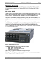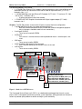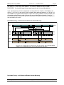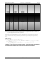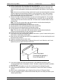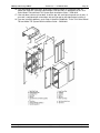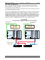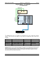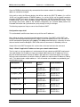
1
IBM System Storage DR550
Version 3.0 ------17 March 2006
Page 1
IBM® System StorageTM DR550 V3.0
Installation, Setup, Operations, and
Problem Determination Guide
(P) IBM part number: 23R5892
*P23R5892*
(2P) EC Level: H81819
*2PH81819*
IBM Storage Systems
Copyright © 2006 by International Business Machines Corporation
IBM System Storage DR550
Version 3.0 ------17 March 2006
Page 2
Table of Contents
INTRODUCTION............................................................................................................. 6
HARDWARE OVERVIEW............................................................................................... 7
IBM System P5 520 ...................................................................................................................................................7
Management Console ..............................................................................................................................................9
IBM TotalStorage DS4100 Midrange Disk System and IBM TotalStorage DS4000 EXP100...................9
IBM TotalStorage SAN Switch .............................................................................................................................10
Accessing the Switch(es).................................................................................................................................10
Dual Node Zoning – without Enhanced Remote Volume Mirroring ......................................................11
Single Node Zoning – without Enhanced Remote Volume Mirroring...................................................12
SOFTWARE OVERVIEW ............................................................................................. 14
High Availability Cluster Multi-Processing (HACMP) for AIX ......................................................................14
System Storage Archive Manager ......................................................................................................................14
System Storage Archive Manager API Client..............................................................................................15
DS4000 Storage Manager Version 9.12.65........................................................................................................15
Content Management Applications....................................................................................................................16
IBM DB2 Content Manager ..............................................................................................................................16
Other Management Applications....................................................................................................................16
DR550 OFFERINGS ..................................................................................................... 18
DR550 Single Node Components .......................................................................................................................18
DR550 Dual Node Components...........................................................................................................................21
DS4100 Logical Volume Configurations ...........................................................................................................25
AIX settings ..............................................................................................................................................................27
System Storage Archive Server Configuration ...............................................................................................28
System Storage Archive Manager Database and Logs ............................................................................28
System Storage Archive Manager Disk Storage Pool...............................................................................28
System Storage Archive Manager Storage Management Policy............................................................28
Automated System Storage Archive Manager Operations......................................................................28
Routine Operations for System Storage Archive Manager ..........................................................................29
Monitoring the Database and Recovery Log Status .................................................................................29
Monitoring Disk Volumes.................................................................................................................................29
Monitoring the Results of Scheduled Operations .....................................................................................29
Installing and Setting Up System Storage Archive Manager API Clients.................................................29
IBM Storage Systems
Copyright © 2006 by International Business Machines Corporation
IBM System Storage DR550
Version 3.0 ------17 March 2006
Page 3
INSTALLATION AND ACTIVATION ............................................................................. 30
Safety Notices..........................................................................................................................................................30
Site Preparation and Planning.............................................................................................................................31
Unpacking and Installing the Rack(s)................................................................................................................32
Positioning the Rack .........................................................................................................................................32
Leveling the Rack...............................................................................................................................................32
Attaching the Rack to a Concrete Floor .......................................................................................................33
Attach the Rack to a Concrete Floor Beneath a Raised Floor ................................................................36
Connecting the Racks in a Suite (applies only to dual node 89.6 TB Configuration) ......................38
Cabling between the Racks.............................................................................................................................40
Cabling to the customer’s Ethernet / IP Network ...........................................................................................41
Single Node Configurations.................................................................................................................................41
Dual Node Configurations ....................................................................................................................................43
Setting up the Management Console ................................................................................................................44
Userid and Password ........................................................................................................................................44
Changing Server Names ..................................................................................................................................44
Connecting AC Power ...........................................................................................................................................47
Configuring the P5 520 Servers ..........................................................................................................................49
User Accounts ....................................................................................................................................................49
Connecting to Gigabit Ethernet (Fibre) Network .......................................................................................50
Connecting to a 10/100/1000 Mbps Ethernet (copper) Network.............................................................51
Procedure for Changing IP Address .............................................................................................................53
Configuring the Dual Node System (P5 520 Servers)....................................................................................55
Connecting to Gigabit Ethernet (Fibre) Network .......................................................................................56
Connecting to 10/100/1000 Ethernet (Copper) Network ...........................................................................58
HACMP Configuration ...........................................................................................................................................59
Procedures for Changing IP Addresses.......................................................................................................59
Cluster Snapshot........................................................................................................................................................72
REMOTE MIRRORING ................................................................................................. 74
Zoning diagrams (single and dual node)..................................................................................................................74
Setting up DR550 for remote mirroring.............................................................................................................77
Recovery from the primary failure......................................................................................................................78
Setting up DR550 for mirroring back to original site.....................................................................................80
OTHER INSTALLATION TOPICS ................................................................................ 81
Changing passwords.............................................................................................................................................81
IBM Storage Systems
Copyright © 2006 by International Business Machines Corporation
IBM System Storage DR550
Version 3.0 ------17 March 2006
Page 4
HACMP Network Considerations........................................................................................................................85
HACMP Configuration in Switched Networks.............................................................................................85
Monitoring the HACMP Cluster ...........................................................................................................................86
Error Notification and Monitoring.......................................................................................................................86
HMC electronic problem reporting ................................................................................................................86
DS4000 SNMP and e-mail setup for error notification..............................................................................94
DS4000 Service Alert.........................................................................................................................................99
Changing TSM HACMPADM password ...........................................................................................................103
Creating an AIX Recovery DVD .........................................................................................................................104
Creating a Root Volume Group Backup on DVD-RAM with Universal Disk Format .......................104
Recovering from a problem using the Recovery DVD ................................................................................106
Boot from the Recovery DVD........................................................................................................................106
Set and Verify Installation Settings .............................................................................................................107
Backing Up the DR550 Data ...............................................................................................................................108
OTHER INFORMATION.............................................................................................. 110
Environmental Specifications............................................................................................................................110
P5 520..................................................................................................................................................................110
DS4100 ................................................................................................................................................................110
DS4000 EXP100 ................................................................................................................................................111
SAN Switches – 2005-B16 ..............................................................................................................................111
7310-CR3 ............................................................................................................................................................111
7316-TF3 .............................................................................................................................................................112
7014-T00 Rack...................................................................................................................................................112
Lost Key Replacement.........................................................................................................................................113
COMPLEMENTARY PRODUCTS .............................................................................. 114
IBM Tape Solutions ..............................................................................................................................................114
Connecting Tape to the DR550.....................................................................................................................114
Single node tape attachment .............................................................................................................................114
Dual node tape attachment ................................................................................................................................115
Data Migration .......................................................................................................................................................116
PROBLEM DETERMINATION.................................................................................... 118
Gathering problem information from the user ..............................................................................................118
Additional sources of information..........................................................................................................................121
Viewing the AIX runtime error log ....................................................................................................................122
Support Web Site ..................................................................................................................................................122
IBM Storage Systems
Copyright © 2006 by International Business Machines Corporation
IBM System Storage DR550
Version 3.0 ------17 March 2006
Page 5
Placing a Service Call ..........................................................................................................................................122
DS4000 Service Alert Notification.....................................................................................................................124
REFERENCES............................................................................................................ 126
UPDATES TO THIS GUIDE........................................................................................ 128
IBM Storage Systems
Copyright © 2006 by International Business Machines Corporation
IBM System Storage DR550
Version 3.0 ------17 March 2006
Page 6
Introduction
IBM® System StorageTM DR550, one of IBM’s Data Retention offerings, is an integrated offering for
clients that need to retain and preserve electronic business records. The DR550 packages storage,
server and software retention components into a lockable cabinet.
Integrating IBM System P5 servers (using POWER5™ processors) with IBM System Storage and
TotalStorage products and IBM System Storage Archive Manager software, this system is designed
to provide a central point of control to help manage growing compliance and data retention needs.
The powerful system, which fits into a lockable cabinet, supports the ability to retain data and helps
prevent tampering alteration. The system’s compact design can help with fast and easy deployment,
and incorporates an open and flexible architecture.
To help clients better respond to changing business environments as they transform their
infrastructure, the DR550 can be shipped with as few as 5.6 terabytes of physical capacity and can
expand up to 89.6 terabytes, of physical capacity (equal to 89.6 million full-length novels) to help
address massive data requirements.
The DR550 is available to be sold by IBM Business Partners certified on all of the solution
components as well as by IBM Direct.
Innovative Technology
At the heart of the offering is IBM System Storage Archive Manager. This new industry changing
software is designed to help customers protect the integrity of data as well as automatically enforce
data retention policies. Using policy-based management, data can be stored indefinitely, can be
expired based on a retention event, or have a predetermined expiration date. In addition, the
retention enforcement feature may be applied to data using deletion hold and release interfaces
which hold data for an indefinite period of time, regardless of the expiration date or defined event.
The policy software is also designed to prevent modifications or deletions after the data is stored.
With support for open standards, the new technology is designed to provide customers flexibility to
use a variety of content management or archive applications.
The System Storage Archive Manager is embedded on an IBM System P5 520 using POWER5+
processors. This entry-level server has many of the attributes of IBM’s high-end servers,
representing outstanding technology advancements.
Tape storage can be critical for long-term data archiving, and IBM provides customers with a
comprehensive range of tape solutions. The IBM System Storage DR550 supports IBM's
TotalStorage Enterprise Tape Drive 3592, IBM System Storage TS1120 drive, and the IBM Linear
Tape Open family of tape products. Write Once Read Many (WORM) cartridges are recommended
due to the permanent nature of data stored with the DR550, it is strongly recommended that the
3592 with WORM cartridges be used to take advantage of tape media encoded to enforce nonrewrite and non-erase capability. This complementary capability will be of particular interest to
customers that need to store large quantities of electronic records to meet regulatory and internal
audit requirements.
The DR550 is available in two basic configurations: single node (one POWER5+ server) and dual
node (two clustered POWER5+ servers).
IBM Storage Systems
Copyright © 2006 by International Business Machines Corporation
IBM System Storage DR550
Version 3.0 ------17 March 2006
Page 7
Hardware Overview
The DR550 includes one or two IBM System P5 520 servers running AIX® 5.3. When configured
with two 520 servers, the servers are setup in an HACMP™ 5.3 configuration. Both P5 520s have
the same hardware configuration. When configured with one 520 server, no HACMP software is
included.
IBM System P5 520
The IBM System P5 520 (referred to hereafter as the P5 520 when discussing the DR550) is a costeffective, high performance, space-efficient server that uses advanced IBM technology. The P5 520
uses the POWER5+ microprocessor, and is designed for use in LAN clustered environments.
The P5 520 is a member of the symmetric multiprocessing (SMP) UNIX servers from IBM. The P5
520 (product number 9131-52A) is a 4-EIA (4U), 19-inch rack-mounted server. The P5 520 is
configured as a 2-core system with 1.9 GHz processors. The total system memory installed is 1024
MB.
The P5 520 includes six hot-plug PCI-X slots, an integrated dual channel Ultra320 SCSI controller,
two 10/100/1000 Mbps integrated Ethernet controllers, and eight front-accessible disk bays
supporting hot-swappable disks (two are populated with 36.4 GB Ultra3 10K RPM disk drives).
These disk bays are designed to provide high system availability and growth by allowing the
removal or addition of disk drives without disrupting service. The internal disk storage is configured
as mirrored disk for high availability.
Figure 1: Front view of P5 520 server
In addition to the disk drives, there are also 3 media bays available.
• Media - dev0 – not used for DR550
• Media – dev1 – Slimline DVD-RAM (FC 1993)
• SCSI tape drive (not included)
From the back of the server, the following ports and slots are included.
PCI-X slots: The P5 520 provides multiple hot-plug PCI-X slots. The number and type of adapters
installed is dependent on the configuration selected.
IBM Storage Systems
Copyright © 2006 by International Business Machines Corporation
IBM System Storage DR550
Version 3.0 ------17 March 2006
Page 8
The following adapters are installed.
• 3 – 2 Gigabit Fibre Channel PCI-X adapters (two for connections to the internal SAN for disk
attachment and one for connection to the internal SAN for tape attachment) (FC 5716) –
located in slots 1, 4, 5
• 1 – 10/100/1000 Mbps dual port Ethernet PCI adapter II (FC 1983 – TX version or FC 1984
– SX version) – located in slot 3
o Used for connection to the client network
• 1 – POWER GXT135P Graphics Accelerator with Digital support adapter (FC 1980) –
located in slot 2
I/O ports: The P5 520 includes several native I/O ports as part of the basic configuration:
• 2 10/100/1000 Ethernet ports (for copper based connections)
o Both are used for connections to the DS4100 and used for management purposes
only (no changes should be made in these connections).
• 2 serial ports (RS232).
o These are not used with DR550.
• 2 USB ports
o One of these is used to connect to the keyboard and mouse – the other port is not
used
• 2 RIO ports
o These are not used by DR550
• 2 HMC (Hardware Management Console) ports
o One is used for connection to the HMC server in the rack
• 2 SPCN ports
o These are not used by DR550
Hot-plug
Power Supply
Hot-plug Power
Supply (Optional)
GX Bus
Slot
Two HMC
ports*
Two
10/100/1000 Mbps
Ethernet ports
Two System ports*
1
2
3
4
5
6
Six hot-plug PCI-X slots:
Two long 64-bit 133 MHz (slots 5, 6)
One short 64-bit 266 MHz (slot 4)
Two short 32-bit 66 MHz (slots 2,3)
One short 64-bit 133 MHz (slot 1)
Two USB
2.0
ports
Two
SPCN
ports
Figure 2: Back view of P5 520 server
The Converged Service Processor2 (CSP) is on a dedicated card plugged into the main system
planar, which is designed to continuously monitor system operations, taking preventive or corrective
actions to promote quick problem resolution and high system availability.
IBM Storage Systems
Copyright © 2006 by International Business Machines Corporation
IBM System Storage DR550
Version 3.0 ------17 March 2006
Page 9
Additional features are designed into pSeries servers to provide an extensive set of reliability,
availability, and serviceability (RAS) features such as improved fault isolation, recovery from errors
without stopping the system, avoidance of recurring failures, and predictive failure analysis.
Additional information on the P5 520 server is available at www.ibm.com/redbooks.
Management Console
Included in the DR550 is a set of integrated management components. This includes the Hardware
Management Console (HMC) as well as a flat panel monitor, keyboard and mouse. The HMC
(7310-CR3) is a dedicated rack-mounted workstation that allows the user to configure and manage
call home support. The HMC has other capabilities (partitioning, Capacity on Demand) that are not
used in the DR550. The HMC includes the management application used to setup call home. To
help ensure console functionality, the HMC is not available as a general purpose computing
resource. The HMC offers a service focal point for the 520 server(s) that are attached. It is
connected to a dedicated port on the service processor of the POWER5 system via an Ethernet
connection. Tools are included for problem determination and service support, such as call-home
and error log notification, through the internet or via modem. The customer will need to supply the
connection to the network or phone system. The HMC is connected to the keyboard, mouse and
monitor installed in the rack.
The IBM 7316-TF3 is a rack-mounted flat panel console kit consisting of a 17 inch (337.9 mm x
270.3 mm) flat panel color monitor, rack keyboard tray, IBM travel keyboard (English only), and the
Netbay LCM switch. This is packaged as a 1U kit and is mounted in the rack along with the other
DR550 components. The Netbay LCM Switch is mounted in the same rack space, located behind
the flat panel monitor. The IBM Travel Keyboard is configured for English. An integrated “mouse” is
included in the keyboard. The HMC and the P5 520 servers are connected to the Netbay LCM
switch so that the monitor and keyboard can access all three servers.
IBM TotalStorage DS4100 Midrange Disk System and IBM TotalStorage
DS4000 EXP100
The DR550 includes one IBM TotalStorage DS4100 Midrange Disk System (hereafter referred to as
the DS4100) in DR550 configurations of 44.8 TBs or less. With 89.6 TB configurations, two
DS4100s are included. The disk capacity used by the DS4100(s) is provided by the IBM
TotalStorage EXP100 (hereafter referred to as the EXP100). Each EXP100 enclosure packaged
with the DR550 includes fourteen 400 GB Serial ATA (SATA) disk drive modules, offering 5.6
Terabytes (TB) of raw physical capacity.
The DS4100 is an affordable, scalable storage server for clustering applications such as the Data
Retention application. Its modular architecture —which includes Dynamic Capacity Expansion and
Dynamic Volume Expansion—is designed to support e-business on demand™ environments by
helping to enable storage to grow as demands increase. Autonomic features such as online
firmware upgrades also help enhance the system’s usability.
One DS4100 supports up to 44.8TB of Serial ATA physical disk storage capacity (seven EXP100
enclosures). Thus for 89.6 TB configurations of the DR550, dual DS4100s are provided, each
capable of supporting up to 44.8 TBs of raw disk capacity. Note, the first rack holds the first 44.8 TB
and the second rack holds the second 44.8 TB.
The DS4100 is designed to allow upgrades while keeping data intact, helping to minimize
disruptions during upgrades. The DS4100 also supports online controller firmware upgrades, to help
IBM Storage Systems
Copyright © 2006 by International Business Machines Corporation
IBM System Storage DR550
Version 3.0 ------17 March 2006
Page 10
provide high performance and functionality. Events such as upgrades to support the latest version of
DS4000 Storage Manager can also often be executed without stopping operations.
IBM DS4100 Storage Server in the DR550 at a glance
Characteristics
Model
RAID controller
Cache
Host interface
Drive interface
EXP100 drives
EXP100 enclosures
RAID
Maximum drives supported
Fans
Management software
1724-100
Dual active 2 GB RAID controllers
512 MB total, battery-backed
4 - Fibre Channel (FC) Switched and FC Arbitrated Loop (FCAL) standard
Redundant 2 Gbps FC-AL connections
400 GB 7200 RPM SATA disk drives
14 400 GB SATA disk drive modules, offering up to 5.6
Terabytes (TB) of physical capacity per enclosure
Level 5 configured. RAID-10 can be configured at the
customer’s site using an optional IBM Services consultant
112 Serial ATA drives (using 8 EXP100 Expansion Units) per
DS4100
Dual redundant, hot-swappable
IBM DS4000 Storage Manager version 9.12.65 (Special
version for exclusive use with DR550)
IBM TotalStorage SAN Switch
Two IBM TotalStorage SAN Fibre Channel Switches are used to interconnect both P5 520 servers
with the DS4100s to create a SAN (dual node configurations). Tape attachment such as the 3592,
TS1120 or LTO can be done using the additional ports on the switches. The switches (2005-B16)
build two independent SANs, which are designed to be fully redundant for high availability. This
implementation in the DR550 is designed to provide high performance, scalability, and high fault
tolerance.
For the single node configurations, only one switch (2005-B16) included. This creates a single
independent SAN and can be used for both disk and tape access.
The 2005-B16 is a 16-port, dual speed, auto-sensing fibre channel switch. Eight ports are
populated with 2 gigabit shortwave transceivers when the DR550 is configured for single copy
mode. Twelve ports are populated with 2 gigabit short wave tranceivers when the DR550 is
configured for enhanced remote volume mirroring. This dual implementation is designed to provide
a fault tolerant fabric topology, to help avoid single points of failure.
IBM SAN Fibre Channel Switch 2005-B16
Each switch in the DR550 comes pre-zoned by ports. Both switches are configured with distinct
zones as illustrated below:
Accessing the Switch(es)
If you need to access the switch(es) to review the zoning information, error messages, or other
information, you will need to connect Ethernet cables (provided by the customer) to the Ethernet port
IBM Storage Systems
Copyright © 2006 by International Business Machines Corporation
IBM System Storage DR550
Version 3.0 ------17 March 2006
Page 11
on the switch. These cables would also need to be connected to the customer network. You can
then access the switch using the IP address. The Userid is ADMIN and the password is
PASSWORD. You should change this password to confirm with site security guidelines.
If you should need to review the configuration or zoning within the switches, the IP address for
switch 1 is 192.168.1.31 and switch 2 (only installed in dual node configurations) is 192.168.1.32.
These addresses should not be changed. To gain access to the switches via the IP network, you
will need to provide Ethernet cables and ports on your existing Ethernet network. Once the
connections have been made, then you can connect to the IP address and use the management
tools provided by the switch.
Dual Node Zoning – without Enhanced Remote Volume Mirroring
Engine1
Zone 1
Zone 2
Slot 5
0
2
1
2
0
3
1
3
4
Zone 3
Slot 5
Slot 1
Slot 4
5
6
Slot 1
Slot 4
2
3
2
3
7
Engine2
Zone 1
Zone 2
4
5
6
7 Zone 3
2005-B16_2
2005-B16_1
DS4100_1
Controller A1
Controller A2
Controller B1
Controller B2
DS4100_2
Controller A1
Controller A2
Controller B1
Controller B2
Note: Zone 3 is configured for use with the tape (TS1120, TS3310, 358x, 3592 with WORM
cartridges are recommended) - ports 5-7 are connected to the tape drives
Dual Node Zoning – with Enhanced Remote Volume Mirroring
IBM Storage Systems
Copyright © 2006 by International Business Machines Corporation
IBM System Storage DR550
Engine1
Version 3.0 ------17 March 2006
Slot 5
Slot 5
Slot 1
Slot 4
Page 12
Slot 1
Slot 4
2005-B16_1
Zone 1
2005-B16_2
0
0
2
1
Zone 2
2
Zone 1
1
3
4
Zone 3
Zone 4
Engine2
5
6
3
Zone 2
4
7
5
6
7
8
8
Zone 4
9
9
Zone 5
Not
Zoned
10
Zone 3
Zone 5
10
11
Not
Zoned
11
DS4100_1
Controller A1
Controller A2
Controller B1
Controller B2
DS4100_2
Controller A1
Controller A2
Controller B1
Controller B2
Connects to Switch in
secondary DR550
Connects to Switch in
secondary DR550
Note: Zone 3 is configured for use with tape (TS1120, LTO Gen 3, or 3592 drives with WORM cartridges are
recommended - ports 5-7 are available to connect to tape drives)
Zones 4 & 5 are configured for use with data replication (DS4100 enhanced remote volume mirroring)
Per IBM recommendations, the ports used to connect the switches are not included in the zones for remote mirroring
Single Node Zoning – without Enhanced Remote Volume Mirroring
9131-52A
Slot 5
Slot 4
Slot 1
2005-B16
Zone 1
0
Zone 2
2
1
3
4
Zone 3
DS4100
Controller A1
5
6
Controller A2
7
Controller B1
Controller B2
Note: Zone 3 is configured for use with the tape (TS1120, TS3310, 358x, 3592 with WORM
cartridges are recommended) - ports 5-7 are connected to the tape drives
Single Node Zoning – with Enhanced Remote Volume Mirroring
IBM Storage Systems
Copyright © 2006 by International Business Machines Corporation
IBM System Storage DR550
Version 3.0 ------17 March 2006
Page 13
Switch Zoning when Remote Mirroring
is installed (Factory Settings)
9131-52A
Zone 1
Slot 5
Slot 4
0
2
2005-B16
1
Zone 2
3
4
Zone 3
Zone 4
Zone 5
5
6
7
8
9
Not
Zoned
DS4100
Slot 1
10
Controller A-1
11
Controller A-2
Controller B-2
Controller B-1
Connects to Switch in
secondary DR550
Note: Zone 3 is configured for use with tape (TS1120, LTO Gen 3, or 3592 drives with WORM cartridges are
recommended - ports 5-7 are available to connect to tape drives)
Zones 4 & 5 are configured for use with data replication (DS4100 enhanced remote volume mirroring)
Per IBM recommendations, the ports used to connect the switches are not included in the zones for remote mirroring
These zoning configurations may be needed if you ever need to rezone the 2005-B16.
For more information, 2005-B16 data sheets can be downloaded from:
http://www-03.ibm.com/servers/storage/san/b_type/san16b-2/express/
Should one of the switches fail (dual node configurations only), the logical volumes within the
DS4100 systems are available through the other controller and switch.
IBM Storage Systems
Copyright © 2006 by International Business Machines Corporation
IBM System Storage DR550
Version 3.0 ------17 March 2006
Page 14
Software Overview
High Availability Cluster Multi-Processing (HACMP) for AIX
The data retention application can be a business critical application. The DR550 can provide a
high availability environment by leveraging the capabilities of AIX and High Availability Cluster
Multi-Processing (HACMP) with dual P5 servers and redundant networks. This is referred to as
the dual node configuration. IBM also offers a single node configuration that does not include
HACMP.
HACMP is designed to maintain as operational applications such as System Storage Archive
Manager if a component in a cluster node fails. In case of a component failure, HACMP is
designed to move the application along with the resources from the active node to the standby
(passive) node in the DR550.
Cluster Nodes
The two P5 520 servers running AIX with HACMP daemons are Server nodes that share
resources—disks, volume groups, file systems, networks and network IP addresses.
In this HACMP cluster, the two cluster nodes communicate with each other over a private
Ethernet IP network. If one of the network interface cards fails, HACMP is designed to preserve
communication by transferring the traffic to another physical network interface card on the
same node. If a “connection” to the node fails, HACMP is designed to transfer resources to
backup node to which it has access.
In addition, heartbeats are sent between the nodes over the cluster networks to check on the
health of the other cluster node. If the passive standby node detects no heartbeats from the
active node, the active node is considered as failed and HACMP is designed to automatically
transfer resources to the passive standby node.
Within the DR550 (dual node configuration only), HACMP is configured as follows:
• The clusters are setup in Hot Standby (active/passive) mode.
• The resource groups are setup in cascading mode.
• The volume group is setup in enhanced concurrent mode.
System Storage Archive Manager
IBM System Storage Archive Manager (this is the new name for Tivoli Storage Manager for Data
Retention) is designed provide archive services and to prevent critical data from being erased or
rewritten. This software can help address requirements defined by many regulatory agencies for
retention and disposition of data. Key features include the following:
• Data retention protection This feature is designed to prevent deliberate or accidental
deletion of data until its specified retention criterion is met. See “Data Retention Protection”
for more information.
• Event-based retention policy - In some cases, retention must be based on an external
event such as closing a brokerage account. System Storage Archive Manager supports
event-based retention policy to allow data retention to be based on an event other than the
storage of the data. See “Defining and Updating an Archive Copy Group” for more
information. This feature must be enabled via the commands sent by the content
management application.
• Deletion hold In order to ensure that records are not deleted when a regulatory retention
period has lapsed but other requirements mandate that the records continue to be
maintained, System Storage Archive Manager includes deletion hold. Using this feature will
IBM Storage Systems
Copyright © 2006 by International Business Machines Corporation
IBM System Storage DR550
•
Version 3.0 ------17 March 2006
Page 15
help prevent stored data from being deleted until the hold is released. See “Deletion Hold”
for more information. This feature must be enabled via the commands sent by the content
management application.
Data encryption - 144.8-bit Advanced Encryption Standard (AES) is now available for the
Archive API Client. Data can now be encrypted before transmitting to the DR550 and would
then be stored on the disk/tape in an encrypted format.
While the software has been renamed, many of the supporting documents have not been renamed
yet. You will see references to SSAM and TSM throughout this document. Overtime, the
documentation will be updated to reflect the new naming conventions.
For more information on System Storage Archive Manager and, refer to the Tivoli Storage Manager
for AIX Version 5.3 Administrator’s Guide, Administrator’s Reference and Quick Start manuals
which can be found on the web at:
http://publib.boulder.ibm.com/infocenter/tivihelp/index.jsp?toc=/com.ibm.itstorage.doc/toc.xml
Select Storage Manager for Data Retention, and then Storage Manager for AIX Server and then the
Administrator’s Guide
System Storage Archive Manager API Client
The System Storage Archive Manager API Client is used, in conjunction with System Storage
Archive Manager server code, as the link to applications that produce or manage information to be
stored, retrieved and retained. Content management applications, such as The IBM DB2® Content
Manager, identify information to be retained. The content management application calls the System
Storage Archive Manager (SSAM) archive API Client to store, retrieve and communicate retention
criteria to the SSAM server. The SSAM API Client must be installed on the application or
middleware server that is used to initiate requests to DR550. The application or middleware server
must call the SSAM API to initiate a task within the DR550.
Some applications and middleware include the API client as part of their code. Others require it to
be installed separately.
DS4000 Storage Manager Version 9.12.65
The DS4000 Storage Manager Version 9.12.65 software (hereafter referred to as Storage Manager)
is only available as part of the DR550 and is not available for download from the web. This version
has been enhanced to provide additional protection.
Storage Manager is designed to support centralized management of the DS4100s in the DR550.
Storage Manager is designed to allow administrators to quickly configure and monitor storage from
a Java™-based GUI interface. It is also designed to allow them to customize and change settings as
well as configure new volumes, define mappings, handle routine maintenance and dynamically add
new enclosures and capacity to existing volumes—without interrupting user access to data. Failover
drivers, performance-tuning routines and cluster support are also standard features of Storage
Manager.
Using the DS4000 Storage Manager, the DS4100 is partitioned into a single partition at the factory.
As shown in later diagrams, the P5 520 servers are connected to the DS4100s via Ethernet cables.
This connection is used to manage the DS4000. For the single node configuration, DS4000
Storage Manager runs in the P5 520 server. For the dual node configuration, DS4000 Storage
Manager runs in both servers. Server #2 is used to manage DS4100 #1 and Server #1 is used to
DS4100 #2 (if present in the configuration).
IBM Storage Systems
Copyright © 2006 by International Business Machines Corporation
IBM System Storage DR550
Version 3.0 ------17 March 2006
Page 16
Note: only this special version of DS4000 Storage Manager should be used with the DR550.
You should not use this version with other DS4000 or FAStT disk systems and should not
replace this version with a standard version of DS4000 Storage Manager (even if a newer
version is available).
Content Management Applications
For the DR550 to function within a customer IT environment, information appropriate to be retained
must be identified and supplied to the DR550. This can be accomplished with a content
management application. The content management application identifies information appropriate to
be retained, and provides this information to the DR550 via the SSAM API Client.
IBM DB2 Content Manager
To assist customers in addressing needs for data retention, IBM delivers DB2 Content Manager
along with business consulting services (as needed).
IBM® DB2® Content Manager provides a foundation for managing, accessing and integrating
critical business information on demand. It lets you integrate all forms of content - document,
web, image, rich media - across diverse business processes and applications, including Siebel,
PeopleSoft and SAP. Content Manager integrates with existing hardware and software
investments, both IBM and non-IBM, enabling customers to leverage common infrastructure,
achieve a lower cost of ownership, and deliver new, powerful information and services to
customers, partners and employees where and when needed. It is comprised of two core
repository products that are integrated with System Storage Archive Manager for storage of
documents into the DR550:
• DB2 Content Manager is optimized for large collections of large objects. It provides
imaging, digital asset management, and web content management. When combined w/
DB2 Records Manager, it also provides a robust records retention repository for
managing the retention of all enterprise documents.
• DB2 Content Manager OnDemand is optimized to manage very large collections of
smaller objects such as statements and checks. It provides output and report
management.
More information on the DB2 Content Manager portfolio of products can be found at the following
http://www-306.ibm.com/software/data/cm/
web site:
There are a number of applications that work with IBM Content Manager to deliver specific
solutions. These applications are designed to use Content Manager functions and can send data to
be stored in DR550.
IBM offers additional applications that are designed to work with the DR550 API. These include:
IBM CommonStore for Exchange Server
IBM CommonStore for Lotus Domino
IBM CommonStore for SAP
IBM Content Manager for Message Monitoring and Retention (CM MMR) (with iLumin)
BRMS (iSeries) (also via IFS to BRMS)
Other Management Applications
You should consult with your application software vendor to determine if your applications support
the DR550 API. A number of application providers have enhanced their software to include this
support. The current list includes:
AXS-One
IBM Storage Systems
Copyright © 2006 by International Business Machines Corporation
IBM System Storage DR550
Version 3.0 ------17 March 2006
Page 17
BrainTribe (formerly Comprendium)
Caminosoft
Ceyoniq
Easy Software
FIleNet
Hummingbird
Hyland Software (OnBase)
Hyperwave
IRIS Software (Documentum Connector)
MBS Technologies (iSeries Connector for IBM CM V5)
OpenText (formerly IXOS)
Princeton Softech Active Archive Solution for PeopleSoft; for Siebel; for Oracle
Saperion
SER Solutions
Symantec Enterprise Vault (formerly KVS)
Waters (Creon Labs, NuGenesis)
Windream
Zantaz
Only applications or middleware using the API can send data to DR550. Information regarding the
System Storage Archive Manager API Client may be found at
publib.boulder.ibm.com/infocenter/tivihelp/index.jsp?toc=/com.ibm.itstorage.doc/toc.xml
Additional information on qualified ISVs may be found at http://www.ibm.com/storage/dr550
IBM Storage Systems
Copyright © 2006 by International Business Machines Corporation
IBM System Storage DR550
Version 3.0 ------17 March 2006
Page 18
DR550 Offerings
DR550 is available in both single and dual node offerings. Each offering can also be customized to
include support for tape, and the appropriate Ethernet connections.
DR550 Single Node Components
The single node DR550 offerings are built with the following components:
Quantity
1
1
1
0-1
Key Hardware Components
7014 Model T00
9131 Model 52A
1724-100
1710-10U
1
2005-B16
1
1
7310-CR3
7316-TF3
Description
RS/6000 System Rack
P5 520
DS4100 Storage Server (includes 5.6 TB of disk capacity)
DS4000 EXP100 Storage Expansion Unit (only installed in
11.2 TB configuration)
TotalStorage SAN Switch - with 8 shortwave transceivers
(there are 12 transceivers when enhanced RVM is included
in the order)
eServer Hardware Management Console
Flat Panel Monitor, Keyboard, and Mouse
The following list is a list of the actual features that are ordered for DR550 (11.2 TB). This list
should not be modified in any way as part of the initial order. IBM’s eConfig tool should be used to
review any changes in the official configurations. Other configurations are also available.
Product
Description
Management Console
7310-CR3
7310-CR3 Rack-mounted Hardware Management Console
0706
Integrate with IBM TotalStorage Storage DR550
0961
Hardware Management Console for POWER5 Licensed Machine Code
4651
Rack Indicator, Rack #1
6458
Power Cord (4M – 14Ft) 400V/14A, IEC320/C13, IEC320/C14
7801
Ethernet Cable, 6M, Hardware Management Console to System Unit
9300
Language Group, US English
Qty
7316-TF3
0706
4202
4242
4269
6350
9300
9911
IBM 7316-TF3 Rack-Mounted Flat Panel Console Kit
Integrate with IBM System Storage DR550
Keyboard/Video/Mouse (LCM) Displays
6 Foot Extender Cable for Displays
USB Conversion Option
Travel Keyboard, US English
Language Group Specify – US English
Power Cord (4M) All (Standard Cord)
1
1
1
1
1
1
1
1
5771-RS1
0612
7000
Initial Software Support 1 Year
Per Processor Software Support 1 Year
Agreement for MCRSA
1
1
1
DR550 Engine #1
9131-52A
9131 Model 52A
0706
Integrate with DR500 -- IBM TotalStorage
Retention Solution single node
1930
1024 MB (2X512MB) DIMMS, 276-PIN, 533 MHZ,
DDR-2 SDRAM
IBM Storage Systems
1
1
1
1
1
1
1
1
1
Copyright © 2006 by International Business Machines Corporation
IBM System Storage DR550
1968
1977
1980
1983
1993
5005
5159
6458
6574
7160
7190
7320
7877
8330
9300
Version 3.0 ------17 March 2006
73.4 GB 10,000 RPM Ultra320 SCSI Disk Drive
Assembly
2 Gigabit Fibre Channel PCI-X Adapter
POWER GXT135P Graphics Accelerator With
Digital Support
IBM 2-Port 10/100/1000 Base-TX Ethernet
PCI-X Adapter
IBM 4.7 GB IDE Slimline DVD-RAM Drive
Software Preinstall
AC Power Supply, 850 W
Power Cable -- Drawer to IBM PDU, 14-foot,
250V/10A
Ultra320 SCSI 4-Pack
IBM Rack-mount Drawer Rail Kit
IBM Rack-mount Drawer Bezel and Hardware
One Processor Entitlement for Processor
Feature # 8330
Media Backplane Card
2-way 1.9 GHz POWER5 Processor Card, 36MB
L3 Cache
Language Group Specify - US English
Page 19
2
3
1
1
1
1
1
1
1
1
1
2
1
1
1
5608-ARM
3868
IBM System Storage Archive Manager
Per Terabytes with 1 Year SW Maintenance
1
6
5608-AR2
3908
TS - ARM, 1 Yr Maint
Per Terabytes SW Maintenance No Charge Registration
6
5692-A5L
0967
0968
0970
0975
1004
1403
2924
3410
5005
5924
System Software
MEDIA 5765-G03 AIX V5.3
Expansion pack
AIX 5.3 Update CD
Microcode Upd Files and Disc Tool v1.1 CD
CD-ROM Process Charge
Preinstall 64 bit Kernel
English Language
CD-ROM
Preinstall
English U/L SBCS Secondary Language
1
1
1
1
1
1
1
1
1
1
1
5765-G03
0034
AIX V5
Value Pak per Processor D5 AIX V5.3
1
1
5771-SWM
0484
Software Maintenance for AIX, 1 Year
D5 1 Yr SWMA for AIX per Processor Reg/Ren
1
1
DS4100#1
1724-100
0707
2210
4603
5605
DS4100 Midrange Disk System
Integrate with IBM System Storage DR550
Short Wave SFP GBIC (LC)
SATA 400GB/7200 Disk Drive Module
LC-LC 5M Fibre Optic Cable
1
1
2
14
2
IBM Storage Systems
Copyright © 2006 by International Business Machines Corporation
IBM System Storage DR550
7711
Version 3.0 ------17 March 2006
Page 20
DS4100 AIX Host Kit
1
EXP100#1
1710-10U
0707
2210
4603
5601
9001
DS4000 EXP100 Storage Expan
Integrate with IBM System Storage DR550
2 Gb Fibre Channel Short Wave GBIC
SATA 400 GB/7200 Drive Module
1M 50u Fiber Optic Cable (LC-LC)
Attach to DS4100
1
1
2
14
2
1
Switch#1
2005-B16
0706
2414
5605
IBM TotalStorage SAN Switch – 16 Port
DR550 Integration
4 Gb SW SFP Transceiver - 4 Pack
Fibre Cable LC/LC 5m multimode
1
1
2
1
Rack
7014-T00
0233
0234
0247
0248
0254
0257
0706
6068
6098
6580
7188
9188
9300
9800
7014-T00 IBM RS/6000 Rack Model T00
Rack Content Specify: 7316-TF3 - 1 EIA
Rack Content Specify: 1710/10U - 3 EIA
Rack Content Specify: 7310/CR2 - 1 EIA
Rack Content Specify: 1 EIA
Rack Content Specify: 1724/100 - 3 EIA
Rack Content Specify: 9131-52A - 4 EIA
DR550 Integration (single node)
Front Door for 1.8 Meter Rack (Flat Black)
Side Panel for 1.8 or 2.0 Meter Rack (Black)
Optional Rack Security Kit
Power Dist Unit-Side Mount, Universal UTG0247 Connector
Power Dist Unit Specify - Base/Side Mount, Universal UTG0247 Connector
US English Nomenclature
United States/Canada Power Cord
1
1
1
1
1
1
1
1
1
2
1
1
1
1
1
The following table highlights the versions used in DR550.
Components
Software or Firmware Levels
DS4100
NVSRAM: N1724F100R912V05
Appware: 06.12.16.00
Bootware: 06.12.16.00
DS4000 EXP100
ESM Firmware 9563
DS4000 Storage Manager
Version 9.12.6500.00
Note: (this is a special version only available with DR550. It
is not specifically ordered, but included with the hardware)
2005-B16
Firmware 4.4.0e (or later)
AIX 5.3
TL 04, with Atape driver 9.6.0.0 and Atldd 6.3.1.0
System Storage Archive
5.3.2.0
Manager
System Storage Archive
5.3 0.0
Manager Client
An integrated management console is part of the DR550 offering. An as option, limited function is
available via a TTY type terminal (customer provided) such as a VT100 or an IBM 3151. The TTY
terminal is connected to the P5 520 server(s) via the serial port on the front of the server. It is
recommended that the integrated management console be used for all management activity.
IBM Storage Systems
Copyright © 2006 by International Business Machines Corporation
IBM System Storage DR550
Version 3.0 ------17 March 2006
Page 21
DR550 Dual Node Components
The dual node DR550 offerings are built with the following components:
Description
Quantity Key Hardware Components
1 or 2 7014 Model T00
RS/6000 System Rack (2nd rack only included in 89.6 TB
configuration
2
9131 Model 52A
P5 520
1 or 2 1724-100
DS4100 Storage Server (2nd DS4100 included in 89.6 TB
configuration)
0-14
1710-10U
DS4000 EXP100 Storage Expansion Unit (1 included for
11.2 TB, 3 included for 14 TB, 7 included for 44.8 TB and
14 included for 89.6 TB configuration)
2
2005-B16
TotalStorage SAN Switch - with 8 shortwave transceivers
(there are 12 transceivers when configured for remote
mirroring)
1
7310-CR3
eServer Hardware Management Console
1
7316-TF3
Monitor, Keyboard, and Mouse
The following list is a list of the actual features that are ordered for DR550 (11.2 TB). This list
should not be modified in any way as part of the initial order. IBM’s eConfig tool should be used to
review the official configurations and any changes that have been implemented.
Product
Description
Management Console
7310-CR3
7310-CR3 Rack-mounted Hardware Management Console
0707
Integrate with IBM TotalStorage Storage DR550
0961
Hardware Management Console for POWER5 Licensed Machine Code
4651
Rack Indicator, Rack #1
6458
Power Cord (4M – 14Ft) 400V/14A, IEC320/C13, IEC320/C14
7801
Ethernet Cable, 6M, Hardware Management Console to System Unit
9300
Language Group, US English
Qty
7316-TF3
0707
4202
4242
4269
6350
9300
9911
IBM 7316-TF3 Rack-Mounted Flat Panel Console Kit
Integrate with IBM System Storage DR550
Keyboard/Video/Mouse (LCM) Displays
6 Foot Extender Cable for Displays
USB Conversion Option
Travel Keyboard, US English
Language Group Specify – US English
Power Cord (4M) All (Standard Cord)
1
1
1
1
1
1
1
1
5771-RS1
0612
7000
Initial Software Support 1 Year
Per Processor Software Support 1 Year
Agreement for MCRSA
1
1
1
DR550 Engine #1
9131-52A
9131 Model 52A
0706
Integrate with DR500 -- IBM TotalStorage
Retention Solution single node
1930
1024 MB (2X512MB) DIMMS, 276-PIN, 533 MHZ,
DDR-2 SDRAM
1968
73.4 GB 10,000 RPM Ultra320 SCSI Disk Drive
IBM Storage Systems
1
1
1
1
1
1
1
1
1
2
Copyright © 2006 by International Business Machines Corporation
IBM System Storage DR550
1977
1980
1983
1993
5005
5159
6458
6574
7160
7190
7320
7877
8330
9300
Version 3.0 ------17 March 2006
Assembly
2 Gigabit Fibre Channel PCI-X Adapter
POWER GXT135P Graphics Accelerator With
Digital Support
IBM 2-Port 10/100/1000 Base-TX Ethernet
PCI-X Adapter
IBM 4.7 GB IDE Slimline DVD-RAM Drive
Software Preinstall
AC Power Supply, 850 W
Power Cable -- Drawer to IBM PDU, 14-foot,
250V/10A
Ultra320 SCSI 4-Pack
IBM Rack-mount Drawer Rail Kit
IBM Rack-mount Drawer Bezel and Hardware
One Processor Entitlement for Processor
Feature # 8330
Media Backplane Card
2-way 1.9 GHz POWER5 Processor Card, 36MB
L3 Cache
Language Group Specify - US English
Page 22
3
1
1
1
1
1
1
1
1
1
2
1
1
1
5608-ARM
3868
IBM System Storage Archive Manager
Per Terabytes with 1 Year SW Maintenance
1
1
5608-AR2
3908
TS - ARM, 1 Yr Maint
Per Terabytes SW Maintenance No Charge Registration
1
5692-A5L
0967
0968
0970
0975
1004
1403
2924
3410
5005
5924
System Software
MEDIA 5765-G03 AIX V5.3
Expansion pack
AIX 5.3 Update CD
Microcode Upd Files and Disc Tool v1.1 CD
CD-ROM Process Charge
Preinstall 64 bit Kernel
English Language
CD-ROM
Preinstall
English U/L SBCS Secondary Language
1
1
1
1
1
1
1
1
1
1
1
5765-F62
0001
HACMP V5
Per Processor with 1 Year maintenance
1
1
5660-HMP
0719
HACMP Reg/Ren: 1Yr
HACMP Base SW MAINT per proc 1Y Reg
1
1
5765-G03
0034
AIX V5
Value Pak per Processor D5 AIX V5.3
1
1
5771-SWM
0484
Software Maintenance for AIX, 1 Year
D5 1 Yr SWMA for AIX per Processor Reg/Ren
1
1
DR550 Engine #2
9131-52A
9131 Model 52A
IBM Storage Systems
Copyright © 2006 by International Business Machines Corporation
IBM System Storage DR550
0706
1930
1968
1977
1980
1983
1993
5005
5159
6458
6574
7160
7190
7320
7877
8330
9300
Version 3.0 ------17 March 2006
Integrate with DR500 -- IBM TotalStorage
Retention Solution single node
1024 MB (2X512MB) DIMMS, 276-PIN, 533 MHZ,
DDR-2 SDRAM
73.4 GB 10,000 RPM Ultra320 SCSI Disk Drive
Assembly
2 Gigabit Fibre Channel PCI-X Adapter
POWER GXT135P Graphics Accelerator With
Digital Support
IBM 2-Port 10/100/1000 Base-TX Ethernet
PCI-X Adapter
IBM 4.7 GB IDE Slimline DVD-RAM Drive
Software Preinstall
AC Power Supply, 850 W
Power Cable -- Drawer to IBM PDU, 14-foot,
250V/10A
Ultra320 SCSI 4-Pack
IBM Rack-mount Drawer Rail Kit
IBM Rack-mount Drawer Bezel and Hardware
One Processor Entitlement for Processor
Feature # 8330
Media Backplane Card
2-way 1.9 GHz POWER5 Processor Card,36MB
L3 Cache
Language Group Specify - US English
Page 23
1
1
2
3
1
1
1
1
1
1
1
1
1
2
1
1
1
5692-A5L
0967
0968
0970
0975
1004
1403
2924
3410
5005
5924
System Software
MEDIA 5765-G03 AIX V5.3
Expansion pack
AIX 5.3 Update CD
Microcode Upd Files and Disc Tool v1.1 CD
CD-ROM Process Charge
Preinstall 64 bit Kernel
English Language
CD-ROM
Preinstall
English U/L SBCS Secondary Language
1
1
1
1
1
1
1
1
1
1
1
5765-G03
0034
AIX V5
Value Pak per Processor D5 AIX V5.3
1
1
5771-SWM
0484
Software Maintenance for AIX, 1 Year
D5 1 Yr SWMA for AIX per Processor Reg/Ren
1
1
5765-F62
0001
HACMP V5
Per Processor with 1 Year maintenance
1
1
5660-HMP
0719
HACMP Reg/Ren: 1Yr
HACMP Base SW MAINT per proc 1Y Reg
1
1
DS4100#1
1724-100
0707
DS4100 Midrange Disk System
Integrate with IBM System Storage DR550
1
1
IBM Storage Systems
Copyright © 2006 by International Business Machines Corporation
IBM System Storage DR550
2210
4603
5605
7711
Version 3.0 ------17 March 2006
Page 24
Short Wave SFP GBIC (LC)
SATA 400GB/7200 Disk Drive Module
LC-LC 5M Fibre Optic Cable
DS4100 AIX Host Kit
2
14
2
1
EXP100#1
1710-10U
0707
2210
4603
5601
9001
DS4000 EXP100 Storage Expan
Integrate with IBM System Storage DR550
2 Gb Fibre Channel Short Wave GBIC
SATA 400 GB/7200 Drive Module
1M 50u Fiber Optic Cable (LC-LC)
Attach to DS4100
1
1
2
14
2
1
Switch#1
2005-B16
0707
2414
5605
IBM TotalStorage SAN Switch – 16 Port
DR550 Integration
4 Gb SW SFP Transceiver - 4 Pack
Fibre Cable LC/LC 5m multimode
Switch#2
2005-B16
0707
2414
5605
IBM TotalStorage SAN Switch – 16 Port
DR550 Integration
4 Gb SW SFP Transceiver - 4 Pack
Fibre Cable LC/LC 5m multimode
Rack
7014-T00
0233
0234
0247
0248
0254
0257
0707
6068
6098
6580
7188
9188
9300
9800
7014-T00 IBM RS/6000 Rack Model T00
Rack Content Specify: 7316-TF3 - 1 EIA
Rack Content Specify: 1710/10U - 3 EIA
Rack Content Specify: 7310/CR2 - 1 EIA
Rack Content Specify: 1 EIA
Rack Content Specify: 1724/100 - 3 EIA
Rack Content Specify: 9131-52A - 4 EIA
DR550 Integration (dual node)
Front Door for 1.8 Meter Rack (Flat Black)
Side Panel for 1.8 or 2.0 Meter Rack (Black)
Optional Rack Security Kit
Power Dist Unit-Side Mount, Universal UTG0247 Connector
Power Dist Unit Specify - Base/Side Mount, Universal UTG0247 Connector
US English Nomenclature
United States/Canada Power Cord
1
1
2
3
1
1
2
3
1
1
1
1
2
1
2
1
1
2
1
1
1
1
1
Other configurations are available, using different amounts of DS4000 EXP100 and DS4100.
The following table highlights the versions used in DR550.
Components
DS4100
DS4000 EXP100
DS4000 Storage Manager
IBM Storage Systems
Software or Firmware Levels
NVSRAM: N1724F100R912V05
Appware: 06.12.16.00
Bootware: 06.12.16.00
ESM Firmware 9563
Version 9.12.6500.00
Note: (this is a special version only available with DR550. It
is not specifically ordered, but included with the hardware)
Copyright © 2006 by International Business Machines Corporation
IBM System Storage DR550
2005-B16
AIX 5.3
HACMP
System Storage Archive
Manager
System Storage Archive
Client
Version 3.0 ------17 March 2006
Page 25
Firmware 4.4.0e (or later)
TL 04, with Atape driver 9.6.0.0 and Atldd 6.3.1.0
5.3 + PTFs
5.3.2.0
5.3.0.0
An integrated console is part of the DR550 offering. As an option, limited function is available via a
TTY type terminal (customer provided) such as a VT100 or an IBM 3151. If this option is used, the
TTY terminal is connected to the serial port on the front of the P5 520 server. It is recommended
that the integrated management console be used for all management activity.
DS4100 Logical Volume Configurations
On the DR550, LUNs will be configured based on the total storage capacity ordered. All disk
capacity is allocated for use by TSM. No disk capacity is set aside for other applications or servers.
Below are the approximate LUN configurations set at the factory. The LUN id column shows the
LUN id as seen from DS4000 Storage Manager. If you view the LUN id from AIX, it will be displayed
as a hexadecimal address.
For 5.6 TB System (single or dual node configurations)
LUN size
2 GB
115 GB
300 GB
2035 GB
2035 GB
380* GB
LUN ID
0
1
2
3
4
5
Hdisk on AIX
hdisk2
hdisk3
hdisk4
hdisk5
hdisk6
hdisk7
Logical Volume
tsmappslv
tsmdblv
tsmloglv
tsmdbbkuplv
tsmstglv1
tsmstglv2
tsmstglv3
File System
/tsm
/tsmDb /tsmLog
/tsmdbbkup
VG Name
TSMApps
TSMDbLogs
TSMDbBkup
For 11.2 TB System (single or dual node configurations)
LUN size
2 GB
115 GB
300 GB
2035 GB
2035 GB
380* GB
2035 GB
2035 GB
600* GB
LUN ID
0
1
2
3
4
5
6
7
8
Hdisk on AIX
hdisk2
hdisk3
hdisk4
hdisk5
hdisk6
hdisk7
hdisk8
hdisk9
hdisk10
Logical Volume
tsmappslv
tsmdblv
tsmloglv
tsmdbbkuplv
tsmstglv1
tsmstglv2
tsmstglv3
tsmstglv4
tsmstglv5
tsmstglv6
File System
/tsm
/tsmDb /tsmLog
/tsmdbbkup
VG Name
TSMApps
TSMDbLogs
TSMDbBkup
File System
/tsm
/tsmDb /tsmLog
/tsmdbbkup
VG Name
TSMApps
TSMDbLogs
TSMDbBkup
For 22.4 TB System (dual node configurations only)
LUN size
2 GB
315 GB
900 GB
2035 GB
2035 GB
380* GB
2035 GB
1900* GB
2035 GB
LUN ID
0
1
2
3
4
5
6
7
9
IBM Storage Systems
Hdisk on AIX
hdisk2
hdisk3
hdisk4
hdisk5
hdisk6
hdisk7
hdisk8
hdisk9
hdisk10
Logical Volume
tsmappslv
tsmdblv
tsmloglv
tsmdbbkuplv
tsmstglv1
tsmstglv2
tsmstglv3
tsmstglv4
tsmstglv5
tsmstglv6
Copyright © 2006 by International Business Machines Corporation
IBM System Storage DR550
2035 GB
600* GB
2035 GB
2035 GB
600* GB
10
11
11
12
13
Version 3.0 ------17 March 2006
hdisk11
hdisk12
hdisk13
hdisk14
hdisk15
Page 26
tsmstglv7
tsmstglv8
tsmstglv9
tsmstglv10
tsmstglv11
For 44.8TB System (dual node configurations only)
LUN size
2 GB
415 GB
1200 GB
2035 GB
2035 GB
280* GB
2035 GB
1600* GB
2035 GB
2035 GB
600* GB
2035 GB
2035 GB
600* GB
2035 GB
2035 GB
600* GB
2035 GB
2035 GB
600* GB
2035 GB
2035 GB
600* GB
LUN ID
0
1
2
3
4
5
6
7
8
9
10
11
12
13
14
15
16
17
18
19
20
21
22
Hdisk on AIX
hdisk2
hdisk3
hdisk4
hdisk5
hdisk6
hdisk7
hdisk8
hdisk9
hdisk10
hdisk11
hdisk12
hdisk13
hdisk14
hdisk15
hdisk16
hdisk17
hdisk18
hdisk19
hdisk20
hdisk21
hdisk22
hdisk23
hdisk24
Logical Volume
tsmappslv
tsmdblv
tsmloglv
tsmdbbkuplv
tsmstglv1
tsmstglv2
tsmstglv2
tsmstglv3
tsmstglv4
tsmstglv6
tsmstglv7
tsmstglv8
tsmstglv9
tsmstglv10
tsmstglv11
tsmstglv12
tsmstglv13
tsmstglv14
tsmstglv15
tsmstglv16
tsmstglv17
tsmstglv18
tsmstglv19
tsmstglv20
File System
/tsm
/tsmDb /tsmLog
/tsmdbbkup
VG Name
TSMApps
TSMDbLogs
TSMDbBkup
File System
/tsm
/tsmDb /tsmLog
/tsmdbbkup
VG Name
TSMApps
TSMDbLogs
TSMDbBkup
For 89.6 TB System (dual node configurations only)
LUN size
2 GB
415 GB
1200 GB
2035 GB
2035 GB
280* GB
2035 GB
1600 GB
2035 GB
2035 GB
600* GB
2035 GB
2035 GB
600* GB
2035 GB
2035 GB
600* GB
2035 GB
2035 GB
LUN ID
0
1
2
3
4
4
5
6
8
9
10
11
12
13
14
15
16
17
18
IBM Storage Systems
Hdisk on AIX
hdisk2
hdisk3
hdisk4
hdisk5
hdisk6
hdisk7
hdisk8
hdisk9
hdisk10
hdisk11
hdisk12
hdisk13
hdisk14
hdisk15
hdisk16
hdisk17
hdisk18
hdisk19
hdisk20
Logical Volume
tsmappslv
tsmdblv
tsmloglv
tsmdbbkuplv
tsmstglv1
tsmstglv2
tsmstglv3
tsmstglv4
tsmstglv5
tsmstglv6
tsmstglv7
tsmstglv8
tsmstglv9
tsmstglv10
tsmstglv11
tsmstglv12
tsmstglv13
tsmstglv14
tsmstglv15
tsmstglv16
Copyright © 2006 by International Business Machines Corporation
IBM System Storage DR550
600* GB
2035 GB
2035 GB
600* GB
2035 GB
2035 GB
600* GB
2035 GB
2035 GB
600* GB
2035 GB
2035 GB
600* GB
2035 GB
2035 GB
600* GB
2035 GB
2035 GB
600* GB
2035 GB
2035 GB
600* GB
2035 GB
2035 GB
600* GB
2035 GB
2035 GB
600* GB
19
20
21
22
23
24
25
26
27
28
29
30
31
32
33
34
35
36
37
38
39
40
41
42
43
44
45
46
Version 3.0 ------17 March 2006
hdisk21
hdisk22
hdisk23
hdisk24
hdisk25
hdisk26
hdisk27
hdisk28
hdisk29
hdisk30
hdisk31
hdisk32
hdisk33
hdisk34
hdisk35
hdisk36
hdisk37
hdisk38
hdisk39
hdisk40
hdisk41
hdisk42
hdisk43
hdisk44
hdisk45
hdisk46
hdisk47
hdisk48
Page 27
tsmstglv17
tsmstglv18
tsmstglv19
tsmstglv20
tsmstglv21
tsmstglv22
tsmstglv23
tsmstglv24
tsmstglv25
tsmstglv26
tsmstglv27
tsmstglv44.8
tsmstglv29
tsmstglv30
tsmstglv31
tsmstglv32
tsmstglv33
tsmstglv34
tsmstglv35
tsmstglv36
tsmstglv37
tsmstglv38
tsmstglv39
tsmstglv40
tsmstglv41
tsmstglv42
tsmstglv43
tsmstglv44
Note* the actual size of the last LUN in each disk drawer is an approximate value. The actual size
may be slightly different from what is published.
Backup times for the SSAM data base will vary, depending on the used portion of the allocated
space. As the data base fills up (could take years to do this, you should expect longer backup
times.
AIX settings
The following has been setup for the AIX server(s)
• Paging space has been increased by 1536 MB. Now DR550 has a paging space of 1536 +
512 = 2048 MB paging space.
• Changed TCP parameter in AIX rfc1323 = 1 <==== the default value was 0.
In addition, FTP and Telnet services have been shut down. All other ports/sockets are blocked with
the exception of those needed by AIX, HACMP and System Storage Archive Manager
IBM Storage Systems
Copyright © 2006 by International Business Machines Corporation
IBM System Storage DR550
Version 3.0 ------17 March 2006
Page 28
System Storage Archive Server Configuration
The System Storage Archive Manager Server settings on the DR550 are (these settings are
different than the default settings. Other parameters use the default settings.
ARCHIVERETENTIONPROTECTION
ON
TCPWINDOWSIZE
63
TCPNODELAY
YES
BUFFERPOOL
512000
SELFTUNEBUFPOOLSIZE
NO
TXNGRPMAX
512
COMMTIMEOUT
300
DBPAGE SHADOW
YES
MAX SESSIONS
100
The following files have been set at the factory:
1. Defined /tsm/files/devconfig (keeps System Storage Archive Manager device configuration
to help in rebuilding the System Storage Archive Manager server within DR550 in case of
System Storage Archive Manager server loss).
2. Defined /tsm/files/volhist (keeps track of volumes used by System Storage Archive
Manager).
See the Tivoli Storage Manager for AIX Administrator’s Guide and Reference manuals for
information on customizing these settings for your needs.
System Storage Archive Manager Database and Logs
For the DR550 configurations (5.6 TB and 11.2 TB), a 100 GB logical volume for the SSAM
database and a 15 GB logical volume for the SSAM log have been preconfigured. For the 22.4 TB
configuration, a 300 GB logical volume for the SSAM database and a 15 GB logical volume for the
SSAM log has been preconfigured. For the 44.8 and 89.6 TB configurations, a 400 GB logical
volume for the SSAM database and 15 GB logical volume for the SSAM log have been
preconfigured. The System Storage Archive Manager database and log volumes are configured
using DS4000 RAID5 storage. System Storage Archive Manager mirroring for the database and log
volumes is not configured.
System Storage Archive Manager Disk Storage Pool
The DR550 has been preconfigured with a single disk storage pool (ARCHIVEPOOL). The raw
logical volumes in the table above have been defined into the ARCHIVEPOOL.
System Storage Archive Manager Storage Management Policy
The DR550 default policy is defined (all are named STANDARD) and the Archive Copy Group in the
STANDARD Management Class specifies the following:
Data is stored into ARCHIVEPOOL
A chronological retention policy to retain the data for 365 days
See the Tivoli Storage Manager for AIX Administrator’s Reference, Guide, and Quick Start manual
for more information on customizing the System Storage Archive Manager policy for your data
environment.
Automated System Storage Archive Manager Operations
DR550 includes schedules used to automate System Storage Archive Manager server
administrative commands. The schedules specify that the operations start and stop during defined
time periods. You may want to change these start and stop windows to suit your situation. See the
IBM Storage Systems
Copyright © 2006 by International Business Machines Corporation
IBM System Storage DR550
Version 3.0 ------17 March 2006
Page 29
TSM for AIX Administrator’s Guide and Reference manuals for help in modifying the administrative
schedules.
Examples of schedules that are setup in the DR550 are:
Backup of the System Storage Archive Manager database is scheduled to run daily at
8am.
Maintain 3 copies of backup and delete older versions (scheduled a job to run daily at
23:59).
Note: It is the responsibility of the customer to set up and verify schedules and database backups.
You should verify that you have appropriate schedules in place to back up your database.
Routine Operations for System Storage Archive Manager
Monitoring the Database and Recovery Log Status
Monitor the System Storage Archive Manager database and recovery usage log to ensure that you
have enough space available for efficient operation. You should pay particular attention to the
maximum utilization percentage (%Util) for both. If more room is needed in that database or
recovery log, shift resources by using the administrator functions outlined in the Tivoli Storage
Manager for AIX Administrator’s Guide and Reference manuals.
Monitoring Disk Volumes
Monitor the status of the volumes for the Tivoli Storage database, recovery log, and the
ARCHIVEPOOL storage pool. If any volumes have a status of Offline or Stale, you must determine
why and correct the situation.
Monitoring the Results of Scheduled Operations
Monitor scheduled administrative to ensure that the schedules are running successfully. This is
particularly relevant if you have set up scheduled backups of the database.
Installing and Setting Up System Storage Archive Manager API
Clients
The DR550 storage interface is the System Storage Archive Manager API Client. You may need to
install the System Storage Archive Manager API Client V5.2.2 or later on the server(s) that are
sending data to the DR550. Your software vendor may offer specific recommendations for defining
System Storage Archive Manager storage management policies, the System Storage Archive
Manager client node names, and System Storage Archive Manager client Include-Exclude lists. You
will also need to point to the network address of the DR550 in the System Storage Archive Manager
Client Communications Options definition.
The following web based education is available from Tivoli and may be beneficial in providing more
information on System Storage Archive Manager. The site for web based training for externals is
the Virtual Tivoli Skill Center- cgse1.cgselearning.com/tivoliskills
IBM Storage Systems
Copyright © 2006 by International Business Machines Corporation
IBM System Storage DR550
Version 3.0 ------17 March 2006
Page 30
Installation and Activation
Safety Notices
A danger notice indicates the presence of a hazard that has the potential of causing death or
serious injury. A caution notice indicates the presence of a hazard that has the potential of causing
moderate or minor personal injury.
Note: For a translation of these notices, see System Unit Safety Information, order number SA232652.
Electrical Safety
Observe the following safety instructions any time you are connecting or disconnecting devices
attached to the workstation.
DANGER
•
•
•
•
•
An electrical outlet that is not correctly wired could place hazardous voltage on metal parts
of the system or the devices that attach to the system. It is the responsibility of the customer
to ensure that the outlet is correctly wired and grounded to prevent an electrical shock.
Before installing or removing signal cables, ensure that the power cables for the system unit
and all attached devices are unplugged.
When adding or removing any additional devices to or from the system, ensure that the
power cables for those devices are unplugged before the signal cables are connected. If
possible, disconnect all power cables from the existing system before you add a device.
Use one hand, when possible, to connect or disconnect signal cables to prevent a possible
shock from touching two surfaces with different electrical potentials.
During an electrical storm, do not connect cables for display stations, printers, telephones, or
station protectors for communications lines.
CAUTION: This product is equipped with a three-wire power cable and plug for the user’s safety.
Use this power cable with a properly grounded electrical outlet to avoid electrical shock.
DANGER: To prevent electrical shock hazard, disconnect all power cables from the electrical outlet
before relocating the system.
Laser Safety Information
CAUTION: This product contains a CD-ROM and a laser module on a PCI card, which are class 1
laser products.
Laser Compliance
All lasers are certified in the U.S. to conform to the requirements of DHHS 21 CFR Subchapter J for
class 1 laser products. Outside the U.S., they are certified to be in compliance with the IEC 825 (first
edition 1984) as a class 1 laser product. Consult the label on each part for laser certification
numbers and approval information.
CAUTION: All IBM laser modules are designed so that there is never any human access to laser
radiation above a class 1 level during normal operation, user maintenance, or prescribed service
conditions. Data processing environments can contain equipment transmitting on system links with
laser modules that operate at greater than class 1 power levels. For this reason, never look into the
end of an optical fiber cable or open receptacle. Only trained service personnel should perform the
inspection or repair of optical fiber cable assemblies and receptacles.
IBM Storage Systems
Copyright © 2006 by International Business Machines Corporation
IBM System Storage DR550
Version 3.0 ------17 March 2006
Page 31
Site Preparation and Planning
Before you install the IBM System Storage DR550 we recommend that you consider several things
to avoid problems during the installation and configuration. The DR550 comes as an almost ready to
use system with a complete assembled hardware in a rack (or two) and preconfigured software.
Nevertheless we review some topics of importance when planning for the physical installation and
configuration of the IBM System Storage DR550 within your environment.
Planning to be done is centered on integrating the rack(s) into the operational IT environment. The
racks themselves are already assembled. To integrate the rack(s) into your environment you have to
plan or validate the following:
• The size of the floor area required by the DR550 rack(s)
– Floor load capacity
– Space needed for expansion
– Service clearance
– Check for potential clearance problems along the access route
• The power requirements
– Multiple 208 volt or 220 volt 30 amp (single phase) power service feeds
2 feeds for 5.6, 11.2 and 22.4 TB configurations (both dual engine and single
engine configurations)
4 feeds for 89.6 TB configurations
– Each feed of a pair are recommended to be on a different AC power feed for
increased availability
– Power cords are shipped with each rack
• Climate control is required (Environmental Class A)
• Cables and Connectors
– RJ-45 to 9-pin converter cable to administer from the front serial port of pSeries
(included) – this is an option that only offers limited functions
• The network environment
– IP addresses
– Check for address conflicts before cabling to your network
The table below shows selected factory IP address settings and provides a column to enter the IP
addresses to be used later when configuring the DR550. Other IP addresses within DR550 do not
need to be changed.
Dual Node Configuration
IP Description
drs_engine1_boot
drs_engine1_stdby
drs_engine2_boot
drs_engine2_stdby
drs_cluster_svc
IP Address from Factory
192.168.1.21
192.168.2.10
192.168.1.23
192.168.2.11
192.168.1.22
IP Address in Network
Single Node Configuration
IP Description
drs_engine
IP Address from Factory
192.168.1.11
IP Address in Network
Refer to Configuring the System (P5 520 Servers) section for additional information on IP
addresses used for the DR550.
IBM Storage Systems
Copyright © 2006 by International Business Machines Corporation
IBM System Storage DR550
Version 3.0 ------17 March 2006
Page 32
Unpacking and Installing the Rack(s)
The DR550 comes integrated into one or two 7014 racks (single node configurations and the 5.6,
11.2, 22.4 and 44.8 TB dual node configurations are always shipped in one rack, while the dual
node 89.6 TB configuration ships in two racks). Unpack Instructions are located in the transparent
sleeve on the exterior of the rack shipping carton. This provides the information necessary to
unpack and remove the rack(s) from the palette. Shipped with each DR550 is a printed copy of the
7014 Series Model T00 and Model T42 System Rack Installation Guide (SA38-0641). This
installation guide provides detailed instructions for positioning, leveling, powering up and checking
out the DR550 racks. A subset of these instructions is contained within and will be sufficient for
installing and setting up the DR550.
Positioning the Rack
After the rack has been placed into its location on the floor, lock each caster by tightening the
locking screw. See the following illustration for the locking screw location. Remove all of the tape
and packing materials from the rack.
2
1
1 Caster
2 Locking Screw
7014 Model T00 Positioning
Use the following to determine the next step:
• If the rack is being bolted to a concrete floor, go to “Attach the Rack to a Concrete Floor”.
•
If the rack is being bolted to a concrete floor beneath a raised floor, go to “Attach the Rack to
a Concrete Floor Beneath a Raised Floor”
•
If the rack is not being attached to the floor, go to “Level the Rack”
Leveling the Rack
To level the rack, do the following:
1. Loosen the jam nut on each leveling foot.
2. Rotate each leveling foot downward until it contacts the surface on which the rack is placed.
3. Adjust the leveling feet downward as needed until the rack is level. When the rack is level,
tighten the jam nuts against the base.
3
2
1
1 Rack Front (base)
2 Leveling Foot (quantity 4)
3 Jam Nut (quantity 4)
7014 Model T00 Leveling
Attach the Stabilizers
Stabilizer plates are only used if you will not be bolting the rack to the floor. If you are going to bolt
the rack to the floor, go to “Attach the Rack to a Concrete Floor”.
IBM Storage Systems
Copyright © 2006 by International Business Machines Corporation
IBM System Storage DR550
Version 3.0 ------17 March 2006
Page 33
CAUTION: The stabilizer must be firmly attached to the bottom rear of the rack to prevent the
rack from turning over when the drawers are pulled out of the rack. Do not pull out or install
any drawer or feature if the stabilizer is not attached to the rack.
To attach the stabilizers to the bottom of the rack, do the following:
1. Align the slots in the stabilizer with the mounting holes at the bottom front of the rack.
2. Install the two mounting screws.
3. Ensure that the base of the stabilizer rests firmly on the floor. Use the Allen wrench that was
supplied with the rack to tighten the mounting screws alternately until they are tight.
4. To install the stabilizer on the rear of the rack, repeat sub steps 1 through 3.
5. Go to “Connect the Power Distribution System”
Attaching the Rack to a Concrete Floor
Obtain the services of a mechanical contractor to attach the rack-mounting plates to the concrete
floor. The mechanical contractor needs to determine that the hardware being used to secure the
rack-mounting plates to the concrete floor is sufficient to meet the requirements for the installation.
To attach the rack to a concrete floor, do the following:
1. Put the rack in its predetermined location and tighten the locking screws on the casters.
2. If installed, remove the top, left and right trim panels. The trim panels are held in place with
spring clips. See the illustration below.
3. Remove the front and rear doors. To remove a rack door, go to “Attaching Rack Doors”.
After the rack doors have been removed, go to sub step 4.
Note: Remember to have the door keys delivered to the appropriate persons.
4. Locate the hardware mounting kit and the two mounting plates. Refer to the following
illustration when reviewing the contents of the hardware mounting kit. The mounting
hardware kit contains the following:
a. 4 Rack-mounting bolts
b. 4 Thin washers
c. 8 Plastic isolator bushings
d. 4 Thick washers
e. 4 Spacer
Note: If you are installing an ac-powered rack, temporarily install the lower plastic
isolator bushings to help you locate the rack mounting plate. After the mounting plate
has been correctly located remove the lower plastic isolator bushings.
5. Position the two mounting plates in the approximate mounting location under the rack.
6. Create a rack-mounting bolt assembly by adding the following items, in the order listed, to
each rack-mounting bolt
a. Thin flat washer
b. Top plastic isolator bushing
c. Thick flat washer
IBM Storage Systems
Copyright © 2006 by International Business Machines Corporation
IBM System Storage DR550
Version 3.0 ------17 March 2006
Page 34
d. Spacer
1
1
2
1 Rack Chassis
2 Top Trim Panel
3 Left Side Trim Panel
4 Right Side Trim Panel
5 Spring Clip
3
4
1 T00 Rack Chassis
2 Rack-Mounting Bolt
3 Thin Washer
4 Top Plastic Isolator
Bushing
5 Spacer
6 Jam Nut
7 Leveling Foot
2
3
4
667
5
6
7
5
7. Insert a rack-mounting bolt assembly through each of the leveling feet.
8. Reposition the rack-mounting plates under the four rack-mounting bolts so that the mounting
bolts are centered directly over the threaded bolt holes.
9. Turn the rack-mounting bolts 4 complete turns into the mounting plates threaded bolt holes.
10. Mark the floor around the edges of both rack-mounting plates.
1
2
3
4
5
6
7
144
8
8
9
10
11
1 Rack-Mounting Bolt
2 Thin Washer
3 Top Plastic Isolator Bushing
4 Thick Washer
5 Spacer
6 Jam Nut
7 Leveling Foot
8 Mounting Plate
9 Threaded Hole (Used to secure
the rack to mounting plate.)
10 Anchor Bolt Hole
11 Traced Pattern (Pattern to be
traced onto the floor using the
mounting plate as a template)
11. Mark the plate bolt-down holes that are accessible through the opening in the rear of the
rack.
12. Remove the rack-mounting bolt assemblies.
13. If you are installing an ac-powered rack, remove the bottom isolator bushing from each of
the leveling feet. If you are installing a dc-powered rack the bottom isolator bushings must
remain installed in each of the leveling feet.
14. Remove the rack-mounting plates from the marked locations.
15. Loosen each of the locking screws on the casters.
16. Move the rack so that it is clear of both areas that were marked on the floor for the rackmounting plate locations.
17. Reposition the mounting plates within the marked areas.
18. Mark the floor at the center of all holes in both rack-mounting plates.
IBM Storage Systems
Copyright © 2006 by International Business Machines Corporation
IBM System Storage DR550
Version 3.0 ------17 March 2006
Page 35
19. Remove the two rack-mounting plates from the marked areas.
20. At the marked location of the threaded rack-mounting bolt holes, drill four clearance holes
into the concrete floor. Each clearance hole should be approximately one inch deep. This
allows the rack-mounting bolts enough room to protrude past the thickness of the mounting
plate.
Note: You must use a minimum of two anchor bolts for each rack-mounting plate to securely
attach the plate to the concrete floor. Because some of the holes in each rack-mounting
plate may align with concrete reinforcement rods embedded in the concrete, some of the
rack-mounting plate holes may not be usable.
21. Select at least two suitable hole locations for each rack-mounting plate bolt. The selected
locations should be as close to the threaded bolt holes as possible. Be sure that the holes
selected at the rear of the rack are accessible. Drill holes at the selected locations into the
concrete floor.
Note: The size of the anchor bolts and concrete anchors must be determined by the
mechanical contractor doing the installation.
22. Position the front-mounting plate over the concrete anchors.
23. Securely bolt the front rack-mounting plate to the concrete floor.
24. Position the rear-mounting plate over the concrete anchors.
25. Securely bolt the rear rack-mounting plate to the concrete floor.
Note: The size of the anchor bolts and concrete anchors must be determined by the
mechanical contractor doing the rack-mounting plate installation.
26. Position the rack over the rack-mounting plates.
27. Insert each of the rack-mounting bolts through a flat washer, a plastic isolator bushing and a
thick washer, and through a leveling foot.
28. Align the four rack-mounting bolts with the four tapped holes in the two mounting plates and
turn three to four rotations.
29. Tighten the locking screw on each caster.
30. Adjust the leveling feet downward as needed until the rack is level. When the rack is level,
tighten the jam nuts against the base of the rack.
3
2
1
1 Rack Front (base)
2 Leveling Foot (quantity 4)
3 Jam Nut (quantity 4)
31. If you have multiple racks that are connected in a suite (bolted to each other), go to
“Installing Multiple Racks Connected in a Suite”. Otherwise, torque the four bolts to 40-50 ftlbs (54-67 nm).
32. If you are not installing doors on your rack, install the top, left, and right trim panel.
33. Connect the power distribution system as described in “Connect the Power Distribution
System”.
34. After all racks are bolted down, go to “Attaching Front or Rear AC Electrical Outlet”.
35. If you are not going to attach a front electrical outlet and you are installing rack doors, go to
“Attaching Rack Doors”
IBM Storage Systems
Copyright © 2006 by International Business Machines Corporation
IBM System Storage DR550
Version 3.0 ------17 March 2006
Page 36
Attach the Rack to a Concrete Floor Beneath a Raised Floor
Obtain the services of a mechanical contractor to attach the rack-mounting plates to the concrete
floor. The mechanical contractor needs to determine that the hardware being used to secure the
rack-mounting plates to the concrete floor is sufficient to meet the requirements for the installation.
To attach the rack to a concrete floor, do the following:
1. Put the rack in its predetermined location and tighten the locking screws on the casters.
2. If installed, remove the top, left and right trim panels. The trim panels are held in place with
spring clips. See the following illustration.
3. If installed, remove the front and rear doors. To remove a rack door, go to “Attaching Rack
Doors”. After the rack doors have been removed, go to the next sub step.
4. Remove the front and rear doors. To remove a rack door, go to “Attaching Rack Doors”.
After the rack doors have been removed, go to sub step 4.
5. Locate the hardware mounting kit and the two mounting plates. Refer to the following
illustration when reviewing the contents of the hardware mounting kit. The mounting
hardware kit contains the following:
a. 4 Rack-mounting bolts
b. 4 Thin washers
c. 8 Plastic isolator bushings
d. 4 Thick washers
e. 4 Spacer
Note: If you are installing an ac-powered rack, temporarily install the lower plastic
isolator bushings to help you locate the rack mounting plate. After the mounting plate
has been correctly located remove the lower plastic isolator bushings.
6. Position the two mounting plates in the approximate mounting location under the rack.
1
1
2
1 Rack Chassis
2 Top Trim Panel
3 Left Side Trim Panel
4 Right Side Trim Panel
5 Spring Clip
3
4
1 T00 Rack Chassis
2 Rack-Mounting Bolt
3 Thin Washer
4 Top Plastic Isolator
Bushing
5 Spacer
6 Jam Nut
7 Leveling Foot
2
3
4
667
5
6
7
5
7. Create a rack-mounting bolt assembly by adding the following items, in the order listed, to
each rack-mounting bolt
a. Thin flat washer
b. Top plastic isolator bushing
c. Thick flat washer
d. Spacer
8. Insert a rack-mounting bolt assembly through each of the leveling feet.
9. Reposition the rack-mounting plates under the four rack-mounting bolts so that the mounting
bolts are centered directly over the threaded bolt holes.
10. Turn the rack-mounting bolts 4 complete turns into the mounting plates threaded bolt holes.
IBM Storage Systems
Copyright © 2006 by International Business Machines Corporation
IBM System Storage DR550
Version 3.0 ------17 March 2006
Page 37
11. Mark the floor around the edges of both rack-mounting plates.
12. Mark the plate bolt-down holes that are accessible through the opening in the rear of the
rack.
13. Remove the rack-mounting bolt assemblies.
14. If you are installing an ac-powered rack, remove the bottom isolator bushing from each of
the leveling feet. If you are installing a dc-powered rack the bottom isolator bushings must
remain installed in each of the leveling feet.
15. Remove the rack-mounting plates from the marked locations.
16. Loosen each of the locking screws on the casters.
17. Move the rack so that it is clear of both areas that were marked on the floor for the rackmounting plate locations.
18. Reposition the mounting plates within the marked areas.
19. Mark the floor at the center of all holes in both rack-mounting plates.
20. Remove the two rack-mounting plates from the marked areas.
21. Drill two clearance holes on each end of each rack-mounting plate. The drilled holes should
be approximately 1 inch deep. This will accommodate any rack-mounting bolt extending past
the rack-mounting plate when securing the rack to the rack-mounting plate.
22. For each rack-mounting plate, select at least two suitable hole locations. Select the hole
locations as close to the threaded hole areas as possible. Be sure the hole locations
selected at the rear of the rack are accessible.
23. Drill pass-through holes in the raised-floor panel. The pass-through holes allow the anchorbolts to be inserted into the rack-mounting plate and pass through the raised floor panel to
the concrete floor.
Note: You must use a minimum of two anchor bolts for each rack-mounting plate to securely
attach the rack-mounting plate through the raised-floor panel to the concrete floor. Because
some of the holes in each rack-mounting plate may align with concrete reinforcement rods
imbedded in the concrete, some of the rack-mounting plate holes may not be usable.
1
2
3
4
5
6
7
144
8
8
9
10
11
1 Rack-Mounting Bolt
2 Thin Washer
3 Top Plastic Isolator Bushing
4 Thick Washer
5 Spacer
6 Jam Nut
7 Leveling Foot
8 Mounting Plate
9 Threaded Hole (Used to secure
the rack to mounting plate.)
10 Anchor Bolt Hole
11 Traced Pattern (Pattern to be
traced onto the floor using the
mounting plate as a template)
24. Transfer the locations of the anchor bolt holes (exclude the clearance holes drilled for the
rack-mounting bolts) from the raised-floor panel to the concrete floor directly beneath, and
mark the hole locations on the concrete floor.
25. Drill holes in the concrete floor to secure the anchor bolts.
26. Position the raised-panel floor back into position over the anchor bolt holes.
27. Position the front-mounting plate within the marked area on the raised-panel floor.
28. Using your anchor bolts, secure the front rack-mounting plate on top of the raised floor and
through to the concrete floor.
29. Position the rear-mounting plate within the marked area on the raised-panel floor.
IBM Storage Systems
Copyright © 2006 by International Business Machines Corporation
IBM System Storage DR550
Version 3.0 ------17 March 2006
Page 38
30. Using your anchor bolts, secure the rear rack-mounting plate on top of the raised floor and
through to the concrete floor.
31. Replace all raised panels that may have been removed when aligning and securing the
anchor bolts to the concrete floor.
32. Align the rack over the front and rear-mounting plates.
33. Insert each of the rack-mounting bolts assemblies through a leveling foot.
34. Align the rack-mounting bolts with the threaded holes in each rack-mounting plate. Turn
each rack-mounting bolt three to four rotations.
36. Tighten the locking screw on each caster.
37. Adjust the leveling feet downward as needed until the rack is level. When the rack is level,
tighten the jam nuts against the base of the rack.
38. If you have multiple racks that are connected as a suite (bolted to each other), go to
“Installing Multiple Racks Connected in a Suite”. Otherwise torque the four bolts to 40-50 ftlbs (54-67 nm).
39. If you are not installing doors on your rack, install the top, left, and right trim panel.
40. Connect the power distribution system as described in “Connect the Power Distribution
System”
41. After the rack is bolted down and you are going to attach a front electrical outlet, go to
“Attaching Front or Rear AC Electrical Outlet”.
42. If you are not going to attach a front electrical outlet and you are installing rack doors, go to
“Attaching Rack Doors”.
Connecting the Racks in a Suite (applies only to dual node 89.6 TB Configuration)
If you are installing a suite of racks, do the following:
1. If they are installed, remove the side panels from each rack. To remove the side panels:
a. Lift the two panel-release tabs up. See the following illustration for the two panel
release tab locations.
b. Pull the panel up and away from the rack chassis. This motion will release the panel
from the two
2. Lower J brackets. Store the side panels away from the work area.
3. Remove the two Z brackets and the two J brackets. These brackets are used to hang the
side panels. See the following illustration.
4. Stand facing the first rack and locate the right side.
5. Install a standoff in the upper-left corner and lower-right corner of the first rack. See the
following illustration for standoff placement locations.
6. Locate the second rack’s left side.
7. Install a standoff in the upper-left corner and lower-right corner of the second rack.
8. Attach the long foam strip as shown in the following illustration. Position the racks together.
9. Align the standoff holes. To align the standoff holes, you may have to adjust the leveling
feet.
10. Install a screw and washer in all four standoff hole positions, as shown in the following
illustration, but do not tighten. After the racks are bolted together, level the racks.
11. Tighten the four screws in the standoff holes.
12. Install the trim pieces that fit between the front and back racks.
13. Install the trim piece that fits on top and between the racks.
14. Install rack filler panels above and below the installed system drawers. The filler panels
cover and seal the open areas at the front of the rack(s).
Note: All open areas located in the front of the rack must also be sealed to ensure that
proper airflow within the rack is maintained.
15. Connect the cables that go between the racks.
IBM Storage Systems
Copyright © 2006 by International Business Machines Corporation
IBM System Storage DR550
Version 3.0 ------17 March 2006
Page 39
16. If you are bolting down the racks, go to either “Attach the Rack to a Concrete Floor” or
“Attach the Rack to a Concrete Floor Beneath a Raised Floor“ as appropriate in the 7014
Series Model T00 and Model T42 System Rack Installation Guide – SA38-0641.
17. If the rack does not have a front door, install the top, left, and right trim panels on all racks. If
your rack is configured with a front door, wait until you get to step eight before installing it.
18. If you are installing stabilizers, go to “Step 4. Attach the Stabilizers” in the 7014 Series Model
T00 and Model T42 System Rack Installation Guide – SA38-0641.
IBM Storage Systems
Copyright © 2006 by International Business Machines Corporation
IBM System Storage DR550
Version 3.0 ------17 March 2006
Page 40
Cabling between the Racks
This section is only applicable to the dual node 89.6 TB configuration of the DR550. At 44.8 TBs of
raw capacity, the first rack is fully populated. Thus to expand the storage capacity beyond 44.8 TBs,
an additional rack is required. Cabling between the racks is accomplished with two LC-LC Fibre
Channel Cables provided with the DR550 and two Ethernet crossover cables (also provided with the
DR550). The cabling between the racks accomplishes two objectives:
• Connects the second DS4100 to the Fibre channel SAN switches (2005-H08s)
• Connects the second DS4100 to the Ethernet ports on the P5 520 server
To connect RACK1 with RACK2, the following four connections should be made:
Rack / EIA
Device
Connector
Rack / EIA
Device
Connector
RACK2 / EIA1
DS4100_2
Ctrl_A
DS4100_2
Ctrl_B
DS4100_2
Ctrl_A
DS4100_2
Ctrl_B
Host 1
RACK1 / EIA17
SAN Switch_1
Port_3
Host 1
RACK1 / EIA23
SAN Switch_2
Port_3
Ethernet
RACK1 / EIA13
DR_Engine_1
Ethernet
Ethernet
RACK1 / EIA13
DR_Engine_1
Ethernet
RACK2 / EIA1
RACK2 / EIA1
RACK2 / EIA1
It is the customer’s responsibility to connect these cables. The following diagram
shows the required FC connections. Orange (dotted) cables represent fibre channels
connections. The black (thin) connections have been done in manufacturing.
89.6 TB Rack FC Interconnections
IN
OUT
IN
OUT
OUT
IN
OUT
OUT
IN
OUT
OUT
IN
OUT
EXP100_1,6
IN
EXP100_1,6
IN
EXP100_1,5
IN
EXP100_1,4
7316-TF3
0
1
2
3
4
5
6
Switch_2
7
IN
A
1
2
OUT
IN
OUT
OUT
IN
OUT
OUT
IN
OUT
OUT
IN
OUT
OUT
IN
OUT
OUT
IN
OUT
OUT
IN
OUT
EXP100_2,7
B
DRS_Engine_2
3
4
5
6
IN
7310-CR3
EXP100_2,6
0
1
2
3
4
5
6
Switch_1
7
IN
EXP100_2,5
IN
A
B
DRS_Engine_1
IN
1
OUT
IN
2
3
4
5
EXP100_2,4
6
OUT
IN
EXP100_2,3
EXP100_1,3
IN
OUT
IN
OUT
IN
EXP100_2,2
EXP100_1,2
IN
OUT
EXP100_1,1
DS4100_1
IBM Storage Systems
IN
OUT
IN
EXP100_2,1
DS4100_2
Copyright © 2006 by International Business Machines Corporation
IBM System Storage DR550
Version 3.0 ------17 March 2006
Page 41
The following diagram shows the required Ethernet connections (green solid lines) that must be
done by the customer between the racks.
8 9 .6 T B R a c k E th e r n e t In te r c o n n e c tio n s
IN
OUT
IN
OUT
OUT
IN
OUT
OUT
IN
OUT
OUT
IN
OUT
E X P 1 0 0 _ 1 ,6
IN
E X P 1 0 0 _ 1 ,6
IN
E X P 1 0 0 _ 1 ,5
IN
E X P 1 0 0 _ 1 ,4
7 3 1 6 -T F 3
0
1
2
3
4
5
6
S w itc h _ 2
7
IN
OUT
IN
OUT
OUT
IN
OUT
OUT
IN
OUT
OUT
IN
OUT
A
E X P 1 0 0 _ 2 ,7
B
D R S _ E n g in e _ 2
1
2
3
4
5
6
IN
7 3 1 0 -C R 3
0
1
2
3
4
5
6
E X P 1 0 0 _ 2 ,6
S w itc h _ 1
7
IN
E X P 1 0 0 _ 2 ,5
A
IN
B
D R S _ E n g in e _ 1
IN
1
OUT
2
3
4
IN
5
OUT
E X P 1 0 0 _ 2 ,4
6
IN
IN
OUT
IN
OUT
IN
IN
OUT
OUT
IN
OUT
OUT
IN
OUT
E X P 1 0 0 _ 2 ,2
E X P 1 0 0 _ 1 ,2
IN
OUT
E X P 1 0 0 _ 2 ,3
E X P 1 0 0 _ 1 ,3
OUT
IN
OUT
IN
E X P 1 0 0 _ 1 ,1
E X P 1 0 0 _ 2 ,1
D S 4100_1
D S 4100_2
Cabling to the customer’s Ethernet / IP Network
The DR550 provides for connecting to the customers Ethernet network using either 10/100 copper
connections or gigabit fibre connections. For DR550 single node configurations, only one Ethernet
connection is needed. For DR550 dual node configurations, four Ethernet connections are required
(this enables HACMP failover if network problems occur). For the dual node configurations, two
connections should be made to each of two customer provided subnets. Typically, it is expected
that the customer will connect the DR550 to their existing network, including existing customer
provided Ethernet switches.
Single Node Configurations
The following diagrams show the connections from an Ethernet perspective. With only one
processing node, there is only a single Ethernet connection to the existing network. The type of
connection (copper or fiber optic) is based on the adapter in the DR550. This choice is made when
the DR550 is ordered.
IBM Storage Systems
Copyright © 2006 by International Business Machines Corporation
IBM System Storage DR550
Version 3.0 ------17 March 2006
Page 42
S in g le N o d e
1 0 / 1 0 0 / 1 0 0 0 ( C o p p e r ) E t h e r n e t C o n n e c t iv it y
I B M s u p p lie d E t h e r n e t
c r o s s o v e r c a b le s
C t r lA
C t r lB
DS4100
2 Gb Fibre Channel Adapter
- Slot 5 (DS4100)
TX PCI-X Adapter - Slot 3
U S B 0 (T 7 )
2 Gb Fibre channel Adapter Slot 4 (DS4100)
1 0 /1 0 0 /1 0 0 0 (T 5 )
1 0 /1 0 0 /1 0 0 0 (T 6 )
2 Port 10/100/1000 Ethernet
HMC1
HMC2
Pwr GXT135p Graphics
Adapter - Slot 2
S y s te m
b o a rd
2 Gb Fibre Channel
Adapter - Slot 1 (tape)
P5 520
U S B 1 (T 8 )
C u s t o m e r s u p p lie d
E t h e r n e t c a b le s
1 0 /1 0 0 /1 0 0 0 E N S w itc h # 1
( c u s t o m e r 's n e t w o r k )
S in g le N o d e
G ig a b it ( F ib e r O p t ic ) E t h e r n e t C o n n e c t iv it y
I B M s u p p lie d E t h e r n e t
c r o s s o v e r c a b le s
C t r lA
C tr lB
D S4100
U S B 0 (T 7 )
2 Gb Fibre Channel Adapter
- Slot 5 (DS4100)
PCI-X Adapter - Slot 3
2 Gb Fibre channel Adapter Slot 4 (DS4100)
1 0 / 1 0 0 /1 0 0 0 ( T 5 )
1 0 / 1 0 0 /1 0 0 0 ( T 6 )
2 Port Gigabit Ethernet SX
HMC1
HMC2
Pwr GXT135p Graphics
Adapter - Slot 2
S y s te m
b o ard
2 Gb Fibre Channel
Adapter - Slot 1 (tape)
P5 520
U S B 1 (T 8 )
C u s t o m e r s u p p lie d
E t h e r n e t c a b le s
G i g a b it E N S w i t c h # 1
( c u s t o m e r 's n e t w o r k )
IBM Storage Systems
Copyright © 2006 by International Business Machines Corporation
IBM System Storage DR550
Version 3.0 ------17 March 2006
Page 43
Dual Node Configurations
Boot is used to indicate the primary connection. There is one Ethernet connection from both
engine_1 and engine_2. Standby is provided as a backup connection in the event of a network
failure to provide an alternate network path.
The diagrams below show the connections to be made from each engine (P5 520) to the customer’s
pair of 10/100 or gigabit Ethernet switches.
For connecting to a gigabit Ethernet network, the boot (primary) connections are made from the first
port of the 2 Port Gigabit Ethernet SX PCI-X adapters in engine_1 and engine_2 to the customer’s
gigabit Ethernet switch (Switch1) .Switch 1 will carry network traffic in a normal situations. The
standby (backup) connections are made from the second port of the 2 Port Gigabit Ethernet SX PCIX Adapter installed on engine_1 and engine_2 to the customer’s gigabit Ethernet switch (Switch2).
Switch2 will carry the network traffic to the DR550 when there is a network failure associated with
connections to Switch1. All gigabit Ethernet connections are to use fiber optic cabling.
Dual Node
10/100/1000 (Copper) Ethernet Connectivity
IBM supplied Ethernet
crossover cables
IBM supplied Ethernet
crossover cables
CtrlB
CtrlA
USB0 (T7)
10/100/1000 (T5)
10/100/1000 (T6)
2 Gb Fibre Channel Adapter
- Slot 5 (DS4100)
HMC1
HMC2
2 Port 10/100/1000 Ethernet
TX PCI-X Adapter - Slot 3
2 Gb Fibre channel Adapter Slot 4 (DS4100)
System
board
USB0 (T7)
USB1 (T8)
USB1 (T8)
HACMP boot connection
HACMP standby - customer supplied cables
Customer supplied
Ethernet cables
10/100/1000 EN Switch #1
(customer's network)
IBM Storage Systems
P5 520 #2 (DRS_Engine_2)
Pwr GXT135p Graphics
Adapter - Slot 2
2 Gb Fibre Channel Adapter
- Slot 5 (DS4100)
10/100/1000 (T5)
10/100/1000 (T6)
Pwr GXT135p Graphics
Adapter - Slot 2
2 Port 10/100/1000 Ethernet
TX PCI-X Adapter - Slot 3
2 Gb Fibre channel Adapter Slot 4 (DS4100)
HMC1
HMC2
2 Gb Fibre Channel
Adapter - Slot 1 (tape)
P5 520 #1 (DRS_Engine_1)
System
board
CtrlB
DS4100#1 (in Rack A)
2 Gb Fibre Channel
Adapter - Slot 1 (tape)
CtrlA
DS4100#2 (in Rack B)
HACMP boot connection
Customer supplied
Ethernet cables
10/100/1000 EN Switch #2
(customer's network)
Copyright © 2006 by International Business Machines Corporation
IBM System Storage DR550
Version 3.0 ------17 March 2006
Page 44
Dual Node
Gigabit (Fiber Optic) Ethernet Connectivity
IBM supplied Ethernet
crossover cables
IBM supplied Ethernet
crossover cables
CtrlB
CtrlA
DS4100#2 (in Rack B)
DS4100#1 (in Rack A)
USB0 (T7)
HMC1
HMC2
10/100/1000 (T5)
10/100/1000 (T6)
2 Gb Fibre Channel Adapter
- Slot 5 (DS4100)
Pwr GXT135p Graphics
Adapter - Slot 2
2 Port Gigabit Ethernet SX
PCI-X Adapter - Slot 3
2 Gb Fibre channel Adapter Slot 4 (DS4100)
2 Gb Fibre Channel Adapter
- Slot 5 (DS4100)
10/100/1000 (T5)
10/100/1000 (T6)
2 Gb Fibre Channel
Adapter - Slot 1 (tape)
HMC1
HMC2
System
board
Pwr GXT135p Graphics
Adapter - Slot 2
2 Port Gigabit Ethernet SX
PCI-X Adapter - Slot 3
2 Gb Fibre channel Adapter Slot 4 (DS4100)
P5 520 #2 (DRS_Engine_2)
P5 520 #1 (DRS_Engine_1)
System
board
CtrlB
2 Gb Fibre Channel
Adapter - Slot 1 (tape)
CtrlA
USB0 (T7)
USB1 (T8)
USB1 (T8)
HACMP standby - customer supplied cables
HACMP boot connection
Customer supplied
Ethernet cables
HACMP boot connection
Customer supplied
Ethernet cables
Gigabit EN Switch #1
(customer's network)
Gigabit EN Switch #2
(customer's network)
Setting up the Management Console
DR550 includes an integrated management console. This console is already connected to each of
the P5 520 servers and to the HMC. Connections are made through the Netbay LCM (Local
Console Manager). To interact with the system software interfaces or to run diagnostics from a
DVD-RAM, it is necessary to use the integrated console.
Userid and Password
The userid for the HMC is HSCROOT with a password of ABC123. You should change this
password as part of the initial installation. Please review your password requirements and create a
password that is appropriate to your installation.
Changing Server Names
IBM Storage Systems
Copyright © 2006 by International Business Machines Corporation
IBM System Storage DR550
Version 3.0 ------17 March 2006
Page 45
You may normally press either the Print Screen key or press the Control key twice to access the
OSCAR® (On Screen Configuration and Activity Reporting) interface. To modify server names on
OSCAR, press Print Screen and then click Setup – Names – Modify to access the screen that
displays the old name and prompts you to add a new name. Enter a new server name and click OK
in the Modify screen; then click OK again in the Names screen., If you do not do this the system will
be in a suspended state until you press the Print Screen twice.
Using the Num Lock key and the keypad in OSCAR to soft switch to servers by port number will
only work when you first set the Num Lock key for a server. For example, when you set Num Lock
on server A, the soft switch to server B and then back to Server A, the LED light on your keyboard
will be lit, but Num Lock will no longer be activated for Server A. You can resolve this by pressing
Num Lock twice to reset, or avoid it by either using your mouse or the number set on the main part
of your keyboard to switch to a different server.
The following diagrams show the connections made in the factory for the single node and dual node
configurations.
Single Node - All Configurations
2 Gb Fibre Channel
Adapter - Slot 5
2 Port 10/100/1000 Ethernet
TX PCI-X Adapter - Slot 3
2 Gb Fibre channel
Adapter - Slot 4
10/100/1000 (T5)
10/100/1000 (T6)
Pwr GXT135p Graphics
Adapter - Slot 2
HMC1
HMC2
2 Gb Fibre Channel
Adapter - Slot 1
P5 520 (DRS_Engine)
System
board
USB0 (T7)
USB1 (T8)
Ethernet Crossover
cable - IBM Supplied
7310-CR3 HMC
Standby
Cat 5 cable connected to
USB Conversion Option
cable (78P5833 7316-TF3 FC 4269 ) - IBM
Supplied
Netbay LCM
Modular phone cable (IBM
Supplied) plugged into right
side phone jack in HMC and
connected to analog phone
jack (supplied by customer)
IBM Storage Systems
7316-TF3 Console with
KVM switch (FC 4202)
and IBM supplied video,
keyboard and mouse
cables (FC 4242)
Cat 5 cable connected to
CT2 Conversion Option
cable (32P1637) connected
to Out port in HMC server IBM Supplied
Copyright © 2006 by International Business Machines Corporation
IBM System Storage DR550
Version 3.0 ------17 March 2006
Page 46
Dual Node - All Configurations
Ethernet Crossover
cables - IBM Supplied
HMC1
HMC2
10/100/1000 (T5)
10/100/1000 (T6)
USB1 (T7)
USB1 (T7)
USB2 (T8)
USB2 (T8)
Cat 5 cable connected to USB
Conversion Option cable (p/n
78P5833 - 7316-TF3 FC 4269 ) IBM Supplied
7310-CR2 HMC
Standby
2 Port 10/100/1000 Ethernet
TX PCI-X Adapter - Slot 3
2 Gb Fibre channel
Adapter - Slot 4
2 Gb Fibre Channel
Adapter - Slot 5
System
board
Pwr GXT135p Graphics
Adapter - Slot 2
P5 520 #1 (DRS_Engine_1)
2 Gb Fibre Channel
Adapter - Slot 5
10/100/1000 (T5)
10/100/1000 (T6)
2 Port 10/100/1000 Ethernet
TX PCI-X Adapter - Slot 3
2 Gb Fibre channel
Adapter - Slot 4
HMC1
HMC2
Pwr GXT135p Graphics
Adapter - Slot 2
P5 520 #2 (DRS_Engine_2)
System
board
Cat 5 cable connected to USB
Conversion Option cable (p/n
78P5833 - 7316-TF3 FC 4269 ) IBM Supplied
Netbay LCM
Modular phone cable (IBM
supplied) plugged into right
side phone jack in HMC and
connected to analog phone
jack (supplied by customer)
7316-TF3 Console with
KVM switch (FC 4202)
and IBM supplied video,
keyboard and mouse
cables (FC 4242)
Cat 5 cable connected to CT2
Conversion Option cable (p/n 32P1637)
connected to Out port in HMC server IBM Supplied
As an option, you can attach an external monitor using the serial ports on the P5 520s. To interact
with the system software interfaces or to run diagnostics from a DVD-RAM using an external device,
you will need to do the following:
• Connect a terminal (or PC) to the serial port FS1 (on the front of the unit) using a nullmodem cable (RJ45 to 9 pin Serial cable which is provided by IBM)
Your PC may need to use an emulator, such as HyperTerminal, often supplied with Windows family
operating systems. Set the emulation mode to vt100 and use the following communication settings:
• 19200 baud
• 8 bit
• 1 stop bit
• No parity
• Xon/Xoff
The following procedure is to connect the ASCII (tty) terminal (or PC) to the P5 520 (this is provided
as information only as it is recommended that you use the integrated console for all DR550
management activity:
1. Before doing this step, read and understand “Read the Safety Notices”.
2. This system drawer is equipped with serial port 1 located in the front (FS1) and rear (S1) of
the system.
3. Use an RJ-45 to 9-pin serial null modem cable (IBM supplied) to connect to the front serial
port FS1.
4. When using FS1, the rear serial port 1 is deactivated.
IBM Storage Systems
Copyright © 2006 by International Business Machines Corporation
IBM System Storage DR550
Version 3.0 ------17 March 2006
Page 47
5. Use a 9-pin to 9-pin serial converter cable (customer supplied) when connecting to the rear
serial port 1.
An ASCII (tty) terminal must be used to configure both P5 520 servers. If you have a single terminal,
you may connect it to one P5 520 and configure the server. Then connect it to the other P5 520
server and configure it. Thus only one terminal is needed as the console in setting up the DR550.
For convenience, the front (FS1) serial port is often preferred.
Dual Node Configurations: Note that P5 520 engine_1 (also referred to as drs_engine_1) is
located in Rack1 position 13. P5 520 engine_2 (also referred to as drs_engine_2) is located in
Rack1 position 19. Also refer to the Cabling between the Racks section for an illustration of the
location of engine_1 and engine_2. It is recommended that you disconnect the cable at the server
side when the console is not in use.
Connecting AC Power
Check the AC Outlets
Refer to the 7014 Series Model T00 and Model T42 Installation Guide for additional information in
the installation and setup of the 7014 Series Model T00 rack.
Before plugging the rack into the AC power source, do the following checks on the AC power
source.
CAUTION: Do not touch the receptacle or the receptacle faceplate with anything other than
your test probes before you have met the requirements in step 8.
1. Turn off the branch circuit breaker for the ac power outlet that the rack will plug into. To the
circuit breaker switch, attach tag S229-0237, which reads “Do Not Operate”.
Note: All measurements are made with the receptacle face plate in the normal installed
position.
2. Some receptacles are enclosed in metal housings. For this type of receptacle, do the
following:
a. Check for less than 1 volt from the receptacle case to any grounded metal structure
in the building, such as a raised-floor metal structure, water pipe, building steel, or
similar structure.
b. Check for less than 1 volt from the receptacle ground pin to a grounded point in the
building.
Note: If the receptacle case or face plate is painted, be sure the probe tip penetrates
the paint and makes good electrical contact with the metal.
c. Check the resistance from the receptacle ground pin to the receptacle case. Check
resistance from the ground pin to the building ground. The readings should be less
than 1.0 ohm, which indicates the presence of a continuous grounding conductor.
3. If any of the three checks made in sub step 2 are not correct, remove the power from the
branch circuit and make the wiring corrections; then check the receptacle again.
Note: Do not use a digital multi-meter to measure grounding resistance in the following
steps.
4. Check for infinite resistance between the ground pin of the receptacle and each of the phase
pins. This is a check for a wiring short to ground or a wiring reversal.
5. Check for infinite resistance between the phase pins. This is a check for a wiring short.
CAUTION: If the reading is other than infinity, do not proceed! Have the customer
make necessary wiring connections before continuing. Do not turn on the branch
circuit CB until all the above steps are satisfactorily completed.
IBM Storage Systems
Copyright © 2006 by International Business Machines Corporation
IBM System Storage DR550
Version 3.0 ------17 March 2006
Page 48
6. Turn on the branch circuit breaker. Measure for the appropriate voltages between phases. If
no voltage is present on the receptacle case or grounded pin, the receptacle is safe to touch.
7. With an appropriate meter, verify that the voltage at the ac outlet is correct.
8. Verify that the grounding impedance is correct by using the ECOS 1020, 1023, B7106,
C7106, or an appropriately approved ground-impedance tester.
Cabling AC
The DR550 rack(s) have sets of AC power rails (left and right) traversing vertically in the rear of the
rack cabinet. Each rail in a set should be connected to a different AC power feed if that is available.
This is to enhance the availability of the rack components. Each power source should be 220V or
200V single phase rated at 30 amps.
For the 5.6 and 11.2 TB configurations, there are two power rails. For the 22.4 and 44.8 TB offering,
there are four power rails. For the 89.6 TB offering, there will be eight power rails, 4 per rack. Power
cords are shipped with each rack (one per rail) to enable cabling to AC power above or below each
rack. Power cords come with NEMA L6-30 connectors.
Each device in the rack is connected to the AC Power Rails. When shipped from the factory each
component will have the AC power switch in the OFF position. The SAN Switch (one in the single
node configuration or two in the dual node configuration) do not have an AC switch, and thus will be
powered up as soon as the rails become energized.
Power on Sequence
The devices in the rack should be powered on in the following sequence:
1. SAN Switch(es) (Before proceeding to step 3, confirm that the SAN Switch(es) have
completed their power on sequencing. This is indicated with a green light showing for
power.)
2. DS4000 EXP100 Serial ATA drives (0 to 14 devices depending on the disk capacity
installed)
3. DS4100 (single device except for 89.6 TB configurations which has two)
4. P5 520 #1 (located at EIA 13-16 in the rack)
5. P5 520 #2 (located at EIA 19-22 in the rack – this is only present in the dual node
configurations)
Similarly, should power need to be shut down, the reverse of the power on sequence should be
followed (once the applications and operating systems have been shutdown):
1. P5 520 #2 (located at EIA 19-22 in the rack – this is only present in the dual node
configurations)
2. P5 520 #1 (located at EIA 13-16 in the rack)
3. DS4100 (single device except for 89.6 TB configurations which has two)
4. DS4000 EXP100 Serial ATA drives (0 to 14 devices depending on the disk capacity
installed)
5. SAN Switch(es)
Connect the Drawer and Device Cables
The DR550 rack(s) are preconfigured at the factory with all drawers and device cables installed. To
check out the system, refer to the RS/6000 and eServer pSeries Diagnostics Information for Multiple
Bus Systems and follow the instructions in the installation checkout procedure.
IBM Storage Systems
Copyright © 2006 by International Business Machines Corporation
IBM System Storage DR550
Version 3.0 ------17 March 2006
Page 49
Configuring the P5 520 Servers
The P5 520 servers within the IBM TotalStorage Data Retention are shipped with particular AIX
security settings. These settings will not allow remote administration tasks initiated via commands
like telnet, remote shell (rsh), file transfer protocol (ftp) or similar. Therefore, you should use the
integrated console for management activities. (You can use an ASCII (tty) terminal if needed – a
connection must be established using the Serial Port 1 of each P5 520 server to administer
(configure) the P5 520 server. Note that one ASCII terminal may be used by connecting to one
server at a time. The procedure for physically attaching the ASCII (tty) terminal was addressed in
the Installation and Activation section. The ASCII terminal, when attached to Serial Port 1, will be
known in AIX as tty0.)
User Accounts
To provide a greater level of security, DR550 is setup with limited access. These restrictions are
built into the DR550 as follows:
• Limited user definitions
• Limited access to commands from certain accounts
• No remote access with authority to make changes
Login
Login with secure shell (ssh) is required for the AIX accounts (dr550, dr550adm, ibmce and root).
User Accounts
The following user accounts have been created. Each has a specific role when using the DR550.
Passwords should be changed in accordance with company policy and guidelines. To enhance
security, certain user accounts do not have any change authority and other accounts can only be
accessed from the integrated console. The following user accounts have been created, with the
following roles and restrictions specified:
AIX
Account
dr550
dr550adm
ibmce
root
IBM Storage Systems
Roles
Access via integrated console to P5 520 servers
(VTY 0) or via the serial port on the front of the P5
520 server (tty 0) – It is recommended that you use
the integrated console
no remote access
Only user who can ‘su’ to root
Home directory /home/dr550
Shell /bin/ksh
Access via integrated console or from remote ASCII
terminal
Home directory /home/dr550adm
Shell - /bin/ksh
console access and remote access
home directory /home/ibmce
shell - /bin/ksh
no direct login
su allowed only from dr550 account
Ability to view log files and perform SM Client tasks
Password set at Factory
dr550
dr550adm
ibmce
d3rv1sh – this password
will need to be changed
during the initial
installation. It is initially
setup to require a change
at the initial login.
Copyright © 2006 by International Business Machines Corporation
IBM System Storage DR550
Version 3.0 ------17 March 2006
Page 50
System Storage Archive Manager
Account
hacmpadm
admin
Roles
System Storage Archive Manager ID for use with
HACMP scripts
Has TSM operator authority
Password set to not expire (you may still want to
change it)
System Storage Archive Manager Administrator ID
Admin login and password is for all TSM
administrative usage
http;//<server ip / dns name>:1580
Password set at Factory
chang3Me
admin
It is the customer’s responsibility to change the default passwords provided above and to
record and protect the new passwords. Changing the password should be done during the
initial installation. The password for root must be changed during the initial installation.
Changing the password for the TSM hacmpadm userid will also require a change in one of
the scripts provided (see Changing the TSM HACMPADM Password)
Configuring the Single Node System (P5 520 Server)
The System Storage DR550 single node configuration consists of a single P5 520 server. No
cluster configuration is included. It is important to understand how the single node configurations
are built so you can make the proper changes to incorporate the DR550 in to your network.
DR550 has been configured at the factory with specific settings. Some of these will need to be
changed. The setup process requires changing one IP address. The DR550 must have network
access to the applications which create or manage data that is to be retained. The DR550 must be
connected in to the customer’s IP network using the Ethernet adapter in slot 1 of the P5 520
server(s). This adapter can either be used to connect to a copper network (must order the TX
adapter) or a fiber optic network (must order the SX adapter) as referenced earlier in this document.
Connecting to Gigabit Ethernet (Fibre) Network
The following diagram shows the network as configured at the factory. The IP address that must be
changed for integration into the customer’s IP network is the address for the single P5 520 server.
You do not need to configure any other addresses on the DR550.
IBM Storage Systems
Copyright © 2006 by International Business Machines Corporation
IBM System Storage DR550
Version 3.0 ------17 March 2006
Page 51
Single Node - SX adapter
IP Addresses
192.168.5.102
192.168.4.101
CtrlA
CtrlB
DS4100
10/100/1000 (T5)
10/100/1000 (T6)
USB0 (T7)
2 Port Gigabit Ethernet SX
PCI-X Adapter - Slot 3
2 Gb Fibre channel Adapter Slot 4 (DS4100)
2 Gb Fibre Channel Adapter
- Slot 5 (DS4100)
HMC1
HMC2
Pwr GXT135p Graphics
Adapter - Slot 2
192.168.4.24
192.168.5.26
System
board
2 Gb Fibre Channel
Adapter - Slot 1 (tape)
P5 520
USB1 (T8)
192.168.1.11
Gigabit EN Switch #1
(customer's network)
The following table shows the IP addresses associated with the server, storage and customer
network. Please note that some addresses may need to be changed while others should not be
changed.
IP Address
DRS_Engine_1
192.168.1.11
192.168.4.24
192.168.5.26
192.168.4.101
192.168.5.102
IP Description
Device
Configuration Need?
drs_engine
AIX
To be changed
drs_engine_DS40001_ctrlA
AIX
Do not change
drs_engine_DS40001_ctrlB
AIX
Do not change
drs_DS40001_ctrlA
DS4100
Do not change
drs_DS40001_ctrlB
DS4100
Do not change
Preconfigured TCP/IP addresses for gigabit Ethernet networks
Connecting to a 10/100/1000 Mbps Ethernet (copper) Network
To connect to a 10/100/1000 Mbps Ethernet network (or 10/100 network), the following diagram
shows how the DR550 is configured at the factory.
IBM Storage Systems
Copyright © 2006 by International Business Machines Corporation
IBM System Storage DR550
Version 3.0 ------17 March 2006
Page 52
Single Node - TX adapter
IP Addresses
192.168.5.102
192.168.4.101
CtrlA
CtrlB
DS4100
10/100/1000 (T5)
10/100/1000 (T6)
USB0 (T7)
2 Gb Fibre Channel Adapter
- Slot 5 (DS4100)
HMC1
HMC2
Pwr GXT135p Graphics
Adapter - Slot 2
2 Port 10/100/1000 Ethernet
TX PCI-X Adapter - Slot 3
2 Gb Fibre channel Adapter Slot 4 (DS4100)
192.168.4.24
192.168.5.26
System
board
2 Gb Fibre Channel
Adapter - Slot 1 (tape)
P5 520
USB1 (T8)
192.168.1.11
Gigabit EN Switch #1
(customer's network)
The following table shows the IP addresses associated with the server, storage and customer
network. Please note that some addresses may need to be changed while others should not be
changed.
IP Address
DRS_Engine_1
192.168.1.11
192.168.4.24
192.168.5.26
192.168.4.101
192.168.5.102
IP Description
Device
Configuration Need?
drs_engine
AIX
To be changed
drs_engine_DS40001_ctrlA
AIX
Do not change
drs_engine_DS40001_ctrlB
AIX
Do not change
drs_DS40001_ctrlA
DS4100
Do not change
drs_DS40001_ctrlB
DS4100
Do not change
Preconfigured TCP/IP addresses for 10/100/1000t Ethernet networks
Important: Make sure to use the correct adapter(s) and port(s) on the IBM eServer p5 520 server(s)
when connecting to your network; check the interface(s) during configuration. Do not connect the
IBM System Storage DR550 to your network if you already use the factory IP addresses for any
other device within your network environment.
IBM Storage Systems
Copyright © 2006 by International Business Machines Corporation
IBM System Storage DR550
Version 3.0 ------17 March 2006
Page 53
Procedure for Changing IP Address
To configure the DR550 for use within your network you must change one IP address from its
factory setting. The change is made to the P5 520 server.
Important: Do not change the factory IP configuration for the DS4100 controllers or
any IP address on the IBM TotalStorage SAN Switch B16.
The following table, which was also provided in the Site Preparation and Planning Section of this
document, may be helpful in recording the IP addresses to be used in your operational environment.
IP Description
drs_engine
IP Address from Factory
192.168.1.11
IP Address in Network
There are different possible ways to change the IP settings. There are various AIX commands,
which are available for these tasks. For convenience, we recommend that you use the System
Management Interface Tool (SMIT) that is part of AIX. This is a quick and efficient tool, and in
addition, the SMIT session is logged into a file (smit.log); the log file can be used to analyze a
situation in case of problems.
Single node configuration steps
Most settings are done using the System Management Interface Tool (SMIT) of AIX. SMIT is an
interactive interface application designed to simplify system management tasks. We start SMIT on
the AIX command line prompt by typing smitty. The smitty command displays a hierarchy of menus
that can lead to interactive dialogues. SMIT builds and runs commands as directed by the user.
Step 1 - Obtain 1 IP address from your network administrator
The first step is to set a new address in conformance with your network. You need to obtain one IP
address from your network administrator. It is suggested that you create a table where you write the
factory IP address and the actual IP address side by side as illustrated. The following steps include
a sample address. Your address will most likely be different.
IP description
AIX interface
Factory IP
address
Actual IP address
drs_engine
en0
192.168.1.21
255.255.255.0
100.100.51.121
255.255.255.0
Step2 - Connect to drs_engine through the management console
1. Login to the IBM eServer p5 520 server drs_engine with user dr550 through the management
console.
Login DR550
Password xxxxxxx
2. Once successfully logged on as dr550, issue the AIX command su - root to switch to root. Now
you have the necessary AIX system rights to change the network settings.
Password xxxxxx
Step 3 - Edit the /etc/hosts file on drs_engine
IBM Storage Systems
Copyright © 2006 by International Business Machines Corporation
IBM System Storage DR550
Version 3.0 ------17 March 2006
Page 54
1. First of all create a copy of the /etc/hosts file that is shipped from factory (see Preconfigured
/etc/hosts file on drs_engine (excerpt)) with the AIX command cp /etc/hosts /etc/hosts.factory.
Preconfigured /etc/hosts file on drs_engine (excerpt)
127.0.0.1
192.168.4.24
192.168.5.26
192.168.1.21
loopback localhost
# loopback (lo0) name/address
drs_engine2_FAStT1_ctrlA drs_engine
drs_engine2_FAStT1_ctrlB drs_engine
drs_engine
2. Open the /etc/hosts file with an editor of your choice, for instance use vi (AIX command to start vi
and open the file is vi /etc/hosts).
If you are not familiar with AIX editors, you may want to use xedit, an X-window based editor. For
the latter, you first need to start an X-session. Start the X-session with the AIX command startx
(see startx manpages for details for issuing man startx). Then open the /etc/hosts file with the
AIX command xedit /etc/hosts, this will open a graphical editor session.
Scroll down to the appropriate line in the hosts file.
Change the preconfigured address according to the table you have prepared in Step 1. Only
change this address, do not change addresses not listed in the table above, or any words in the
/etc/hosts file.
Custom-made /etc/hosts file on drs_engine (excerpt)
127.0.0.1
loopback localhost
# loopback (lo0) name/address
192.168.4.24 drs_engine2_FAStT1_ctrlA drs_engine
192.168.5.26 drs_engine2_FAStT1_ctrlB drs_engine
100.100.51.121 drs_engine (remember, this is a sample address – you will need to provide the
address provided by your network administrator)
3. Save the file and exit the editor by pressing Save and Close on the scroll bar.
Step 4 - Change the TCP/IP address for the interface en3
1. From the AIX command line start SMIT Change / Show Characteristics of a Network Interface
with the command smitty chinet.
2. Select the network interface you want to change, en0, until it is highlighted. Press Enter to
change. In the INTERNET ADDRESS (dotted decimal) field, type the new IP address that was
provided by the network administrator (100.100.51.121 is our sample address). In the Network
MASK (hexadecimal or dotted decimal) field, type the network mask 255.255.255.0 of the new
network. Press Enter.
3. Check the result of the command at the COMMAND STATUS window of SMIT. The Command
field shows OK while the text below says en0 changed. Escape SMIT by pressing F10.
Step 5 - Verify the new IP address
From the AIX command line use the command ping for all the addresses, especially the new
address, to verify their correct working.
IBM Storage Systems
Copyright © 2006 by International Business Machines Corporation
IBM System Storage DR550
Version 3.0 ------17 March 2006
Page 55
Ping xx.xx.xx.xx hit ctrl c to break out of the ping command
Step 6 - Edit the IBM System Storage Archive Manager client option file (dsm.sys)
You need to adjust the IBM Tivoli Storage Manager (ITSM) client system options file, so that the
ITSM API or any ITSM client (dsmadmc) can find the IBM System Storage Archive Manager server.
On the p5 520 server, replace the value in the dsm.sys file for the tcpserveraddress with your new
HACMP cluster service address. We recommend that you do NOT use a dot address, for instance
100.100.51.121, instead, use the TCP/IP domain name instead, that is drs_engine.
Tip: When using the TCP/IP domain name for the tcpserveraddress field in the IBM
System Storage Archive Manager client system options file (dsm.sys), you do not
need to change the value after a network reconfiguration. This is not true, when you
use the dot address.
Step 7 - Logoff all sessions
After successful configuration you should exit all shells with the AIX command exit. Depending on
the actual shells, you must type the exit command more than once. For example, enter exit one
time to close the shell of root and one time to close the shell of dr550. Repeat it until you see the
AIX login prompt on the management console session.
Configuring the Dual Node System (P5 520 Servers)
The System Storage DR550 dual node offering is composed of a two node cluster (using HACMP),
in an active – passive mode. It has been configured for automatic failover with the primary node
being drs_engine1. Once the primary node has been recovered, then fall back will occur
automatically.
During the failover, the cluster will automatically move the resources, such as the physical disks,
logical volumes, and file systems to the surviving node. System Storage Archive Manager will
automatically start and allow for data access activities to continue. When the fall back occurs, the
cluster will stop System Storage Archive Manager from running and start it on the primary node,
along with all the other resources.
It is important to understand the network topology when configuring HACMP. For example, it is
important to understand which IP addresses refer to the BOOT (PUBLIC or customers network)
network, the SERVICE (or cluster IP Address) and the STANDBY (the customers IP address on a
different subnet that will provide connectivity in the event of a failure of the BOOT IP address).
The DR550 has been configured at the factory with the fore mentioned IP addresses. The setup
process requires changing five IP addresses to their network IP addresses on both nodes. At a
minimum, three areas of the DR550 must be configured as a part of initial setup as follows:
1. IP Network Configuration - The DR550 must have IP network access to the applications
which create the data to be retained. The DR550 must be connected into the customer’s IP
network using:
a. four 10/100 copper Ethernet ports (links)
or
b. four gigabit fiber optic Ethernet ports (links)
Each of these four ports must be configured with IP addresses consistent with the
customer’s IP address schema.
IBM Storage Systems
Copyright © 2006 by International Business Machines Corporation
IBM System Storage DR550
Version 3.0 ------17 March 2006
Page 56
2. HACMP Reconfiguration – After the four IP addresses have been configured that are
consistent with the customer’s IP address schema, HACMP must be reconfigured with these
IP addresses specified.
3. Change /usr/tivoli/tsm/client/ba/bin/dsm.sys:
SErvername TSM
COMMmethod
TCPip
TCPPort
1500
192.168.1.22 <=== cluster ip
TCPServeraddress
address or DNS host name
The following sections explain how to configure each of the above steps.
IP Network Address Configuration
The IBM System Storage DR550 can connect to a 10/100/1000 Mbps copper based Ethernet
network, or 1000 Mbps (gigabit) fiber optic based Ethernet network. Setup and configuration for
connecting to 10/100/1000 Mbps and the gigabit Ethernet networks is addressed in the following
sections. There is one dual port network adapter in each P5 520 server. The IBM Dual Port Gigabit
Ethernet-SX PCI-X Adapter or IBM Dual Port Base TX Ethernet adapter is found in the P5 520s
(PCI-X slot 1). This adapter is used to connect to the customer’s Ethernet network.
To use the IBM System Storage DR550 you must change the IP network addresses set at the
factory to conform to your IP network address schema. This results in one task: the setting of IP
addresses for multiple adapters.
Connecting to Gigabit Ethernet (Fibre) Network
The following diagram shows the network as configured at the factory. The addresses that must be
changed for integration into the customer’s IP network are stored on both P5 520 servers.
Addresses for both nodes are stored on each server. You do not need to configure any other
addresses on the DR550.
The following table shows the IP addresses associated with the servers, storage and customer
network. Please note that some addresses may need to be changed while others should not be
changed.
IP Address
DRS_Engine_1
192.168.1.21
192.168.2.10
192.168.1.22
192.168.3.10
192.168.4.23
192.168.5.25
192.168.4.103
192.168.5.104
DRS_Engine_2
192.168.1.23
192.168.2.11
192.168.3.11
IBM Storage Systems
IP Description
Device
Configuration Need?
drs_engine1_boot
drs_engine1_stdby
drs_cluster_svc
drs_engine1_hrtbeat
drs_engine1_DS40002_ctrlA
drs_engine1_DS40002_ctrlB
drs_DS40002_ctrlA
drs_DS40002_ctrlB
AIX
AIX
AIX / HACMP
AIX / HACMP
AIX
AIX
DS4100
DS4100
To be changed
To be changed
To be changed
Do not change
Do not change
Do not change
Do not change
Do not change
drs_engine2_boot
drs_engine2_stdby
drs_engine2_hrtbeat
AIX
AIX
AIX/HACMP
To be changed
To be changed
Do not change
Copyright © 2006 by International Business Machines Corporation
IBM System Storage DR550
192.168.4.24
192.168.5.26
192.168.4.101
192.168.5.102
Version 3.0 ------17 March 2006
Page 57
drs_engine2_DS40001_ctrlA
AIX
Do not change
drs_engine2_DS40001_ctrlB
AIX
Do not change
drs_DS40001_ctrlA
DS4100
Do not change
drs_DS40001_ctrlB
DS4100
Do not change
Preconfigured TCP/IP addresses for gigabit Ethernet networks
Dual Node
Gigabit (Fiber Optic) IP Addresses
192.168.5.102
192.168.4.101
192.168.5.104
192.168.4.103
CtrlB
CtrlA
DS4100#2 (in Rack B)
DS4100#1 (in Rack A)
USB0 (T7)
10/100/1000 (T5)
10/100/1000 (T6)
2 Gb Fibre Channel Adapter
- Slot 5 (DS4100)
HMC1
HMC2
2 Port Gigabit Ethernet SX
PCI-X Adapter - Slot 3
2 Gb Fibre channel Adapter Slot 4 (DS4100)
192.168.4.24
192.168.5.26
2 Gb Fibre Channel Adapter
- Slot 5 (DS4100)
2 Port Gigabit Ethernet SX
PCI-X Adapter - Slot 3
2 Gb Fibre channel Adapter Slot 4 (DS4100)
Pwr GXT135p Graphics
Adapter - Slot 2
10/100/1000 (T5)
10/100/1000 (T6)
2 Gb Fibre Channel
Adapter - Slot 1 (tape)
192.168.5.25
192.168.4.23
HMC1
HMC2
System
board
Pwr GXT135p Graphics
Adapter - Slot 2
P5 520 #2 (DRS_Engine_2)
P5 520 #1 (DRS_Engine_1)
System
board
CtrlB
2 Gb Fibre Channel
Adapter - Slot 1 (tape)
CtrlA
USB0 (T7)
USB1 (T8)
USB1 (T8)
192.168.1.21
HACMP boot
connection
192.168.2.11 HACMP standby connection
192.168.2.10 HACMP standby connection
192.168.1.23
HACMP boot
connection
Gigabit EN Switch #1
(customer's network)
Gigabit EN Switch #2
(customer's network)
To configure the DR550 for use within your network you have to change five IP addresses from their
factory settings. The changes are made on each of the P5 520 servers. No changes are needed on
the DS4100 or the 2005-B16.
The following table, which was also provided in the Site Preparation and Planning Section of this
document, may be helpful in recording the IP addresses to be used in your operational environment.
IP Description
drs_engine1_boot
drs_engine1_stdby
drs_engine2_boot
drs_engine2_stdby
drs_cluster_svc
IBM Storage Systems
IP Address from Factory
192.168.1.21
192.168.2.10
192.168.1.23
192.168.2.11
192.168.1.22
IP Address in Network
Copyright © 2006 by International Business Machines Corporation
IBM System Storage DR550
Version 3.0 ------17 March 2006
Page 58
Connecting to 10/100/1000 Ethernet (Copper) Network
The connection to the customer’s 10/100/1000 Mbps Ethernet (copper) network is provided by the
IBM Dual Port Base TX Ethernet-PCI-X Adapter, located in PCI slot 1 (on the very left side) of each
P5 520 server.
This is illustrated in the figure below. It is important not to change the IP addresses on the P5 520
servers for the attachment of the DS4100 servers nor change the IP addresses on the DS4100
storage servers.
Dual Node
10/100/1000 (Copper) IP Addresses
192.168.5.102
192.168.4.101
192.168.5.104
192.168.4.103
CtrlB
CtrlA
USB0 (T7)
10/100/1000 (T5)
10/100/1000 (T6)
USB0 (T7)
2 Gb Fibre Channel Adapter
- Slot 5 (DS4100)
HMC1
HMC2
2 Port 10/100/1000 Ethernet
TX PCI-X Adapter - Slot 3
2 Gb Fibre channel Adapter Slot 4 (DS4100)
192.168.4.24
192.168.5.26
2 Gb Fibre Channel Adapter
- Slot 5 (DS4100)
2 Port 10/100/1000 Ethernet
TX PCI-X Adapter - Slot 3
2 Gb Fibre channel Adapter Slot 4 (DS4100)
Pwr GXT135p Graphics
Adapter - Slot 2
10/100/1000 (T5)
10/100/1000 (T6)
2 Gb Fibre Channel
Adapter - Slot 1 (tape)
192.168.4.23
192.168.5.25
HMC1
HMC2
System
board
Pwr GXT135p Graphics
Adapter - Slot 2
P5 520 #2 (DRS_Engine_2)
P5 520 #1 (DRS_Engine_1)
System
board
CtrlB
DS4100#1 (in Rack A)
2 Gb Fibre Channel
Adapter - Slot 1 (tape)
CtrlA
DS4100#2 (in Rack B)
USB1 (T8)
USB1 (T8)
192.168.1.21
HACMP boot
connection
192.168.2.11 HACMP standby connection
192.168.2.10 HACMP standby connection
192.168.1.23
HACMP boot
connection
10/100/1000 EN Switch #1
(customer's network)
10/100/1000 EN Switch #2
(customer's network)
The following table shows the IP addresses associated with the servers, storage and customer
network. Please note that some addresses may need to be changed while others should not be
changed.
IP Address
DRS_Engine_1
192.168.1.21
192.168.2.10
192.168.1.22
192.168.3.10
192.168.4.23
192.168.5.25
IBM Storage Systems
IP Description
Device
drs_engine1_boot
drs_engine1_stdby
drs_cluster_svc
drs_engine1_hrtbeat
drs_engine1_DS40002_ctrlA
drs_engine1_DS40002_ctrlB
AIX
AIX
AIX / HACMP
AIX / HACMP
AIX
AIX
Configuration Need?
To be changed
To be changed
To be changed
Do not change
Do not change
Do not change
Copyright © 2006 by International Business Machines Corporation
IBM System Storage DR550
192.168.4.103
192.168.5.104
DRS_Engine_2
192.168.1.23
192.168.2.11
192.168.3.11
192.168.4.24
192.168.5.26
192.168.4.101
192.168.5.102
Version 3.0 ------17 March 2006
drs_DS40002_ctrlA
drs_DS40002_ctrlB
DS4100
DS4100
Page 59
Do not change
Do not change
drs_engine2_boot
AIX
To be changed
drs_engine2_stdby
AIX
To be changed
drs_engine2_hrtbeat
AIX / HACMP
Do not change
drs_engine2_DS40001_ctrlA
AIX
Do not change
drs_engine2_DS40001_ctrlB
AIX
Do not change
drs_DS40001_ctrlA
DS4100
Do not change
drs_DS40001_ctrlB
DS4100
Do not change
Preconfigured TCP/IP addresses for 10/100/1000 Ethernet
Each connection should be to a different 10/100/1000 Ethernet switch, which are elements of the
customer’s network. The reason to use different switches is to enhance network availability to the
DR550. The boot network is the network for normal usage. The second network is the standby
network which is used in case of problems with the boot network.
It is important not to change the TCP/IP addresses on the P5 520 servers for the attachment of the
DS4100 servers nor change the TCP/IP addresses on the DS4100 storage servers.
HACMP Configuration
When changing the IP addresses, you should use the integrated console to make these changes. If
the integrated console is not working, the serial port on the front of each P5 520 server is available
for connection to a TTY terminal (provided by the customer). The console works best with a physical
ASCII terminal such as IBM 3151 or vt100 or a PC workstation running a terminal emulator such as
hyperterm, emulating vt100.
HACMP heartbeat information is exchanged between the two nodes through the host bus adapters
(Ethernet) in slot 3 of the P5 520s. This connection is used to monitor the network and server,
ensuring that a failure does not cause an interruption in data access.
The HACMP configuration needs to be modified when the solution is deployed in the customer
environment. The boot and the standby addresses will have to be modified to be compatible with the
customer subnet that they connect to. It is a best practice recommendation to have them (boot and
standby) on different subnets.
Procedures for Changing IP Addresses
To configure the DR550 for the use with your network you have to change five IP addresses from
their factory settings. The changes are made on both P5 520 servers. No changes are needed on
the DS4100 or the 2005-B16.
The following table, which was also provided in the Site Preparation and Planning Section of this
document, may be helpful in recording the IP addresses to be used in your operational environment.
IP Description
Drs_engine1_boot
Drs_engine1_stdby
Drs_engine2_boot
Drs_engine2_stdby
Drs_cluster_svc
IBM Storage Systems
IP Address from Factory
192.168.1.21
192.168.2.10
192.168.1.23
192.168.2.11
192.168.1.22
IP Address in Network
Copyright © 2006 by International Business Machines Corporation
IBM System Storage DR550
Version 3.0 ------17 March 2006
Page 60
Once the DR550 has been physically connected to the customer network, the following IP
addresses need to be changed:
Using smit or smitty, the Ethernet devices that will be used for the BOOT IP address (i.e. en5 for
10/100, en1 for gigabit) and the STANDBY address (i.e. en3 for 10/100, en2 for gigabit) need to be
changed. HACMP also requires changes to the configuration. HACMP configuration menu must be
invoked through smit or smitty (Configure HACMP Communication Interface/Devices menu). Once
the changes have been made to the HACMP configuration, the customer must perform the
Extended Verification and Synchronization (smitty hacmp) to verify the changes.
The following sequence of steps assumes the utilization of SMIT:
Configuration steps detail
This section details and illustrates how to set up all five new IP addresses.
Most settings are done using the System Management Interface Tool (SMIT) of AIX. SMIT is an
interactive interface application designed to simplify system management tasks. We start SMIT on
the AIX command line prompt by typing smitty. The smitty command displays a hierarchy of menus
that can lead to interactive dialogues. SMIT builds and runs commands as directed by the user.
Usage of the name SMIT throughout this section refers to the tool and not to the command.
Step 1 - Obtain 5 applicable IP addresses from your network administrator
The first step is to set new addresses in conformance with your network and HACMP requirements.
You need to obtain five IP addresses from your network administrator (four IP addresses will use
physical network connections and one IP address will represent a virtual connection). We suggest
that you create a table where you write the factory IP addresses and the actual IP addresses side by
side. (This table includes sample addresses. You will need to use the addresses provided by your
network administrator.)
IP description
AIX interface
Factory IP
address
Actual IP address
drs_engine1_boot
en0
192.168.1.21
255.255.255.0
100.100.51.121
255.255.255.0
drs_engine1_stdby
en1
192.168.2.10
255.255.255.0
100.100.52.110
255.255.255.0
drs_cluster_svc
n/a
192.168.1.22
255.255.255.0
100.100.51.122
255.255.255.0
drs_engine2_boot
en0
192.168.1.23
255.255.255.0
100.100.51.123
255.255.255.0
drs_engine2_stdby
en1
192.168.2.11
255.255.255.0
100.100.52.111
255.255.255.0
IBM Storage Systems
Copyright © 2006 by International Business Machines Corporation
IBM System Storage DR550
Version 3.0 ------17 March 2006
Page 61
Step 2 - Connect to drs_engine1 through the management console (Engine1)
1. From the integrated console, use the PRT Scr key to access the IBM eServer p5 520 server
drs_engine1. Hit Enter to see the login prompt.
Login dr550
Password xxxxxx
2. Once successfully logged on as dr550, issue the AIX command su - root to switch to root. Now
you have the necessary AIX system rights to change the network settings and to reconfigure
HACMP.
Step 3 - Stop HACMP (if necessary)
1. Check if HACMP is running or stopped with the AIX command lssrc -g cluster.
2. If it is running, stop HACMP on each node. It is assumed there is no data traffic when stopping,
since this is the implementation phase. It can take several minutes to stop HACMP. After
HACMP is stopped, go on with the next step.
The following steps describe the procedure for stopping cluster services on a single node or on both
nodes in the cluster by executing the C-SPOC /usr/es/sbin/cluster/sbin/cl_clstop command on one
of the cluster nodes. When stopping multiple nodes, C-SPOC stops them sequentially, not in
parallel. If any node specified to be stopped is inactive, the shutdown operation aborts.
Important: When stopping cluster services, minimize activity on the system. If the
node you are stopping is currently providing highly available services, notify users of
your intentions if their applications will be unavailable. Let them know when services
will be restored.
1. Log in to any of the IBM eServer p5 520 servers; use dr550 and switch to root.
You can switch to root with the AIX command su - root.
2. On the AIX command line start SMIT by issuing the command smitty clstop
3. Use the default settings and change nothing when you want to stop only one of the nodes (the
one you are logged in) with a graceful shutdown mode.
Tip: Because the DR550 is running a two node HACMP cluster, to stop only one of
the both nodes is not a usual task. To stop only one node is needed for maintenance
tasks only. Hence the normal stopping procedure for HACMP in the DR550 always
includes the stopping of both nodes.
IBM Storage Systems
Copyright © 2006 by International Business Machines Corporation
IBM System Storage DR550
Version 3.0 ------17 March 2006
Page 62
Use the F4 key in the Stop Cluster Services on these nodes field when you want to stop the
cluster services on both nodes. A pop-up window (Stop Cluster Nodes on these nodes) appears.
Select both nodes with the F7 key. Both nodes are marked in front of the line. Press Enter.
If you want to change the shutdown mode, press F4 in the appropriate line. A pop-up windows
(Shutdown Mode) appears. Select the shutdown mode and press Enter.
The selected shutdown mode refers to the following types of shutdown:
– graceful: Shut down after the /usr/es/sbin/cluster/events/node_down_complete script is run on
the node to release its resources. The other cluster node does not take over the resources of
the stopped node.
– takeover (graceful with takeover): Shut down after the
/usr/es/sbin/cluster/events/node_down_complete script runs to release its resources. The
other node takes over the resources of the stopped node. You cannot shut down cluster
services on the other cluster node if you select this type of shutdown.
IBM Storage Systems
Copyright © 2006 by International Business Machines Corporation
IBM System Storage DR550
Version 3.0 ------17 March 2006
Page 63
– forced: Shut down immediately. The node retains control of all its resources. You can use this
option to bring down a node while you perform maintenance or make a change to the cluster
configuration such as adding a network interface. The node’s applications remain available,
except for those that access enhanced concurrent mode volume groups (but without the
services of HACMP for AIX daemons).
Important: It is very important that you only use forced shutdown on one cluster
node at a time, and for as short a time as possible. When you need to stop
cluster services for an extended period and on more than one cluster node,
you should use one of the other options (either graceful or graceful with
takeover).
4. Back on the Stop Cluster Services screen, check that the node or nodes are shown in the
appropriate line, make sure you specified the correct shutdown mode, and press Enter.
5. The system stops the cluster services on the nodes specified. SMIT displays a command status
window. It should display an OK message in the upper left corner. If not, you have to analyze the
given messages at the same window, fix the problem, and start the process again.
If the stop operation fails, check the C-SPOC utility log file named /tmp/cspoc.log for error
messages. This file contains the command execution status of the C-SPOC command executed
on each cluster node.
6. Quit the SMIT session: Press F10 or ESC+0.
7. Verify on the AIX command line, that all HACMP services are stopped successful. Use the
command lssrc -g cluster. Typically, it will take a few minutes to stop the Cluster Manager
(clstrmgrES). HACMP is stopped completely, when the lssrc -g cluster command returns with no
services running.
Step 4 - Edit the /etc/hosts file on drs_engine1
1. First of all create a copy of the /etc/hosts file that is shipped from factory (see Preconfigured
/etc/hosts file on drs_engine1 and drs_engine2 (excerpt)) with the AIX command cp /etc/hosts
/etc/hosts.factory.
Preconfigured /etc/hosts file on drs_engine1 and drs_engine2 (excerpt)
127.0.0.1
#
#
Engine 1
#
192.168.1.22
192.168.1.21
192.168.2.10
#
#
Engine 2
#
192.168.1.23
192.168.2.11
192.168.4.24
192.168.5.26
loopback localhost
# loopback (lo0) name/address
drs_cluster_svc
drs_engine1_boot drs_engine1 #en0
drs_engine1_stdby drs_engine1 #en1
drs_engine2_boot drs_engine2 #en0
drs_engine2_stdby
#en1
drs_engine2_FAStT1_ctrlA
#en2
drs_engine2_FAStT1_ctrlB
#en3
IBM Storage Systems
Copyright © 2006 by International Business Machines Corporation
IBM System Storage DR550
Version 3.0 ------17 March 2006
Page 64
2. Open the /etc/hosts file with an editor of your choice, for instance use vi (AIX command to start vi
and open the file is vi /etc/hosts).
If you are not familiar with AIX editors, it may be easier to use xedit, an X-window based editor.
For the latter, you first need to start an X-session. Start the X-session with the AIX command
startx (see startx manpages for details by issuing man startx). Then open the /etc/hosts file with
the AIX command xedit /etc/hosts, this will open a graphical editor session.
Scroll down to the appropriate line in the hosts file
Change all of the preconfigured addresses according to the table you have prepared in Step 1 Ob. Only change these addresses, do not change addresses not listed in the table above, or any
words in the /etc/hosts file. Change the addresses in all stanzas of the /etc/hosts file. That is, you
have to change five addresses.
Custom-made /etc/hosts file on drs_engine1 and drs_engine2 (excerpt)
127.0.0.1
loopback localhost
# loopback (lo0) name/address
#
#
Engine 1
#
100.100.51.122 drs_cluster_svc
100.100.51.121 drs_engine1_boot drs_engine1 #en0
100.100.52.110 drs_engine1_stdby drs_engine1 #en1
#
#
Engine 2
#
100.100.51.123 drs_engine2_boot drs_engine2 #en0
100.100.52.111 drs_engine2_stdby
#en1
192.168.4.24 drs_engine2_FAStT1_ctrlA
#en2
192.168.5.26 drs_engine2_FAStT1_ctrlB
#en3
3. Save the file and exit the editor by pressing save and close on the scroll bar.
Step 5 - Change the TCP/IP addresses for the interfaces en2 and en3
1. From the AIX command line start SMIT Change / Show Characteristics of a Network Interface
with the command smitty chinet.
Select the first network interface you want to change, en2, until it is highlighted. Press Enter to
change. In the INTERNET ADDRESS (dotted decimal) field, type the new IP address
100.100.52.110. In the Network MASK (hexadecimal or dotted decimal) field, type the network
mask 255.255.255.0 of the new network. Press Enter.
Check the result of the command at the COMMAND STATUS window of SMIT. The Command
field shows OK while the text below says en2 changed. Escape SMIT by pressing F10.
2. From the AIX command line start SMIT Change / Show Characteristics of a Network Interface
with the command smitty chinet.
Select the second network interface you want to change, for instance en3, until it is highlighted.
Press Enter to change. In the INTERNET ADDRESS (dotted decimal) field, type the new IP
IBM Storage Systems
Copyright © 2006 by International Business Machines Corporation
IBM System Storage DR550
Version 3.0 ------17 March 2006
Page 65
address 100.100.51.121. In the Network MASK (hexadecimal or dotted decimal) field, type the
network mask 255.255.255.0 of the new network. Press Enter.
Check the result of the command at the COMMAND STATUS window of SMIT. The Command
field shows OK while the text below says en3 changed. Escape SMIT by pressing F10.
Step 6 - Connect to drs_engine2 through the management console (Engine2)
1. Use the PrtSc key on the Keyboard Video Mouse (KVM) keyboard to reach the console. Select
drs-engine2 (or whatever name you are using). Login to the P5 520 with user dr550. . Hit Enter
to get the login screen.
Login dr550
Password xxxxxx
2. Once successfully logged on as dr550, issue the AIX command su - root to switch to root. Now
you have the necessary AIX system rights to change the network settings and to reconfigure
HACMP.
su – root
Password xxxxxx
Step 7 - Edit the /etc/hosts file on drs_engine2
1. First of all create a copy of the /etc/hosts file that is shipped from factory with the AIX command
cp /etc/hosts /etc/hosts.factory.
2. Open the /etc/hosts file with an editor of your choice, for instance use vi (AIX command to start vi
and open the file is vi /etc/hosts).
If you are not familiar with AIX editors, we suppose you use xedit, an X-window based editor.
For the latter, you first need to start an X-session. Start the X-session with the AIX command
startx (see startx manpages for details by issuing man startx). Then open the /etc/hosts file with
the AIX command xedit /etc/hosts, this will open a graphical editor session.
Change the all the preconfigured addresses according to the table you have prepared in Step1.
Only change these addresses, do not change addresses not listed in the table above, or any
words in the /etc/hosts file. Change the addresses in all stanzas of the /etc/hosts file. That is, you
have to change five addresses.
3. Save the file and exit the editor by pressing Save and Close on the scroll bar.
Step 8 - Change the TCP/IP addresses for the interfaces en2 and en3
1. From the AIX command line start SMIT Change / Show Characteristics of a Network Interface
with the command smitty chinet.
Select the first network interface you want to change, for instance en2, until it is highlighted.
Press Enter to change. In the INTERNET ADDRESS (dotted decimal) field, type the new IP
address 100.100.52.111. In the Network MASK (hexadecimal or dotted decimal) field, type the
network mask 255.255.255.0 of the new network. Press Enter.
Check the result of the command at the COMMAND STATUS window of SMIT. The Command
field shows OK while the text below says en2 changed. Escape SMIT by pressing F10.
2. From the AIX command line start SMIT Change / Show Characteristics of a Network Interface
with the command smitty chinet.
IBM Storage Systems
Copyright © 2006 by International Business Machines Corporation
IBM System Storage DR550
Version 3.0 ------17 March 2006
Page 66
Select the second network interface you want to change, for instance en3, until it is highlighted.
Press Enter to change. In the INTERNET ADDRESS (dotted decimal) field, type the new IP
address 100.100.51.123. In the Network MASK (hexadecimal or dotted decimal) field, type the
network mask 255.255.255.0 of the new network. Press Enter.
Check the result of the command at the COMMAND STATUS window of SMIT. The Command
field shows OK while the text below says en3 changed. Escape SMIT by pressing F10.
Step 9 - Verify the new addresses are working
1. From the AIX command line use the command ping for all the addresses (except the cluster
service address) to verify they are working correctly. Because you are logged in to drs_engine2,
start to ping on drs_engine2. See Ping command to verify IP addresses are working for the ping
command and its results. Stop the ping command each time a result is displayed with the Ctrl+C
key combination.
Ping command to verify IP addresses are working
# ping 100.100.51.123
PING 100.100.51.123: (100.100.51.123): 89.6 data bytes
64 bytes from 100.100.51.123: icmp_seq=0 ttl=255 time=0 ms
64 bytes from 100.100.51.123: icmp_seq=1 ttl=255 time=0 ms
64 bytes from 100.100.51.123: icmp_seq=2 ttl=255 time=0 ms
^C
----100.100.51.123 PING Statistics---3 packets transmitted, 3 packets received, 0% packet loss
Round-trip min/avg/max = 0/0/0 ms
You should check all 4 addresses with the ping command.
1. Use the Keyboard Video Mouse (KVM) switch to go back to drs_engine1, that is, use the PrtSc
key and select drs_engine1 (or whatever name you are using). Since you never logged off from
that engine, you do not need to identify yourself again. Use the ping command again to verify all
addresses (except the cluster service address) are working correctly. Stop the ping command
each time a result is displayed with the Ctrl+C key combination.
Important: Network connectivity is important for HACMP functionality. Verify network
connectivity any time you make changes to the network interfaces or network
environment.
Step 10 - Remove network from the HACMP cluster
Regardless on what engine you are, start the SMIT HACMP menus by typing smitty hacmp on an
AIX command line.
1. Go to Extended Configuration -> Extended Topology Configuration -> Configure HACMP
Networks -> Remove a Network from the HACMP Cluster. In the Select a Network to
Remove window, select net_ether_01 (make sure not to select net_ether_02, because this is the
HACMP heartbeat network) and press Enter.
2. In the ARE YOU SURE? window, press Enter to proceed. Check that the result is OK, press F3
twice.
IBM Storage Systems
Copyright © 2006 by International Business Machines Corporation
IBM System Storage DR550
Version 3.0 ------17 March 2006
Page 67
Step 11 - Define the new HACMP network
Still within the HACMP menus of SMIT, configure the new HACMP network for both nodes.
1. Go to Configure HACMP Nodes -> Change/Show a Node in the HACMP Cluster and select
node drs_engine1. Highlight the Communication Path to Node field and press F4 to select a
new path for this node. From the list, select the new boot IP address drs_engine1_boot
(100.100.51.121 – this is just an example, use the address you received from the network
administrator) and press Enter. Press Enter again to change the path and verify the result is OK.
2. Press F3 twice. Go to Change/Show a Node in the HACMP Cluster again and select node
drs_engine2. Highlight the Communication Path to Node field (where the old value for the path
is displayed) and press F4 to select a new path for this node. From the list, select the new boot IP
address drs_engine2_boot (100.100.51.123) and press Enter. Press Enter again to change the
path and verify the result is OK.
3. Step back by pressing F3 (should be four times), until you reach the Extended Configuration
window. Select Discover HACMP-related Information from Configured Nodes and verify the
result is OK. Escape with F3.
4. Go to Extended Topology Configuration -> Configure HACMP Networks -> Add a Network
to the HACMP Cluster and select ether below the discovered IP-based network types stanza. In
the Network Name field type net_ether_01 and verify that the correct netmask for your network
is presented in the Netmask field. Change the Enable IP Address Takeover via IP Aliases field
to No (you can use the Tab key or select with F4 key). Press Enter and verify the result is OK.
Press the F3 key three times.
5. In the Extended Topology Configuration go to Configure HACMP Communication
Interfaces/Devices -> Add Communication Interfaces/Devices and select Add Discovered
Communication Interface and Devices. Select Communication Interfaces. Select
net_ether_01 and press Enter.
In the list, scroll down and select the boot (en3) and standby (en2) interfaces for both nodes with
the F7 key. Make sure you selected four interfaces in all. Press Enter and verify the result is OK.
Use the F3 key three times.
Step 12 - Create the network resource cluster address within HACMP
1. Go to Extended Resource Configuration -> HACMP Extended Resources Configuration ->
Configure HACMP Service IP Labels/Addresses -> Add a Service IP Label/Address ->
Configurable on Multiple Nodes, select net_ether_01 and press Enter.
2. In the IP Label/Address field, press F4. From the list, select drs_cluster_svc and press Enter.
Press Enter again to start the SMIT process and verify that the result is OK.
Step 13 - Add the new network resource to the HACMP resource group
1. Press F3 (normally five times) until you reach the Extended Configuration window. Go to
Extended Resource Configuration -> HACMP Extended Resource Group Configuration ->
Change/Show Resources and Attributes for a Resource Group, select drs_450_rg and press
Enter.
2. In the Service IP Label/Addresses field, press F4. Select drs_cluster_svc and press Enter.
Press Enter again to start the SMIT process and verify that the result is OK.
IBM Storage Systems
Copyright © 2006 by International Business Machines Corporation
IBM System Storage DR550
Version 3.0 ------17 March 2006
Page 68
Step 14 - Verify and synchronize the HACMP cluster
1. Use the F3 key (normally four times) to go back to the Extended Configuration window. Go to
Extended Verification and Synchronization and press Enter.
2. In the next window use the default settings and press Enter.
3. Check the SMIT result screen for an OK status and quit SMIT with the F10 key.
Step 15 - Start the HACMP cluster
Now that the configuration of the HACMP cluster is completed, the cluster can be started.
Whether you start it for the first time as would normally be the case after the procedure above, or as
part of the normal operations of the DR550, the procedure is the same. The procedure is listed
below.
The following steps describe the procedure for starting cluster services on a single node or both
nodes in the cluster by executing the C-SPOC /usr/es/sbin/cluster/sbin/cl_rc.cluster command on
one of the cluster nodes.
Tip: Because the DR550 is running a two node HACMP cluster, to start only one of
the both nodes is not a usual task. To start only one node is needed for maintenance
tasks only. Hence the normal starting procedure for HACMP in the DR550 always
includes the starting of both nodes.
1. Log in to either of the P5 520 servers (such as drs_engine1). Login in a user dr550and switch to
root. You can switch to root with the AIX command su - root.
Login dr550
Password xxxxxx
su – root
Password xxxxxx
2. On the AIX command line start SMIT by issuing the command smitty cl_admin.
3. Go to Manage HACMP Services -> Start Cluster Services and press Enter.
4. Use the default settings when you want to start only one of the both nodes (recommended for
maintenance tasks only). Press Enter.
Use the F4 key in Start Cluster Services on these nodes field when you want to start the cluster
services on both nodes (recommended). A pop-up window (Start Cluster Nodes on these nodes)
appears. Select both nodes with the F7 key. Both nodes are marked in front of their line. Press
Enter.
IBM Storage Systems
Copyright © 2006 by International Business Machines Corporation
IBM System Storage DR550
Version 3.0 ------17 March 2006
Page 69
Back on the Start Cluster Services screen, check that both nodes are shown in the appropriate
line and press Enter.
5. To start the cluster services may take a few minutes. Do not interrupt this process and wait for the OK
message at the end of the process.
6. When command execution completes, and HACMP Cluster Services are started on all nodes
specified; SMIT displays a command status window. It should display an OK message in the
upper left corner. If not, you have to analyze the given messages at the same window, fix the
problem, and start the process again.
If cluster services fail to start on any cluster node, check the C-SPOC utility log file named
/tmp/cspoc.log for error messages. This file contains the command execution status of the CSPOC command executed on each cluster node.
IBM Storage Systems
Copyright © 2006 by International Business Machines Corporation
IBM System Storage DR550
Version 3.0 ------17 March 2006
Page 70
7. Go to System Management (C-SPOC) -> Manage HACMP Services -> Show Cluster Services
and press Enter.
8. Check the SMIT result screen. It should display an OK message in the upper left corner, and three
running cluster subsystems and their AIX process id (PID).
9. Quit the SMIT session: Press F10 or ESC+0.
Tip: The HACMP cluster will automatically start the IBM System Storage Archive
Manager server. Depending on your DR550 configuration, it may take several
minutes to start the ITSM server. So, if an ITSM login fails directly after HACMP start,
try again later.
.
Step16 - Edit the IBM System Storage Archive Manager client option file (dsm.sys)
You need to adjust the IBM Tivoli Storage Manager (ITSM) client system options file, so that the
ITSM API or any ITSM client (like dsmadmc) can find the IBM System Storage Archive Manager
server.
IBM Storage Systems
Copyright © 2006 by International Business Machines Corporation
IBM System Storage DR550
Version 3.0 ------17 March 2006
1. On the first IBM eServer p5 520 server drs_engine1, replace the value in the
Page 71
/usr/tivoli/tsm/client/ba/bin/dsm.sys file for the tcpserveraddress with your new HACMP cluster
service address. We recommend that you do NOT use a dot address, for instance
100.100.51.122 (if you must use an address, you should use the address provided by your
network administrator), use the TCP/IP domain name instead, that is drs_service_svc.
To replace the value, use an editor of your choice, for instance use vi (AIX command to start vi
and open the file is vi /usr/tivoli/tsm/client/ba/bin/dsm.sys).
If you are not familiar with AIX editors, you may want to use xedit, an X-window based editor. For
the latter, you first need to start an X-session. Start the X-session with the AIX command startx
(see startx manpages for details by issuing man startx). Then open the
/usr/tivoli/tsm/client/ba/bin/dsm.sys file with the AIX command xedit
/usr/tivoli/tsm/client/ba/bin/dsm.sys this will open a graphical editor session.
2. Save the file and exit the editor by using Save and Close on the scroll bar.
3. Connect to the IBM System Storage Archive Manager server from drs_engine1 with the
command dsmadmc. Login with the ITSM administrator admin and his password. Verify the
connection with the ITSM command query session. Exit the administrative command line client
with the ITSM command quit.
4. Switch to the second server, using the Prt Scr key. On the second P5 520 server drs_engine2,
replace the value in the /usr/tivoli/tsm/client/ba/bin/dsm.sys file for the tcpserveraddress with your
new HACMP cluster service address. We recommend that you do NOT use a dot address, for
instance 100.100.51.122 (if you must use an address, then use the address provided by the
network administrator), use the TCP/IP domain name instead, that is drs_service_svc.
To replace the value, use an editor of your choice, for instance use vi (AIX command to start vi
and open the file is vi /usr/tivoli/tsm/client/ba/bin/dsm.sys).
If you are not familiar with AIX editors, we suppose you use xedit, an X-window based editor. For
the latter, you first need to start an X-session. Start the X-session with the AIX command startx
(see startx manpages for details by issuing man startx). Then open the
/usr/tivoli/tsm/client/ba/bin/dsm.sys file with the AIX command xedit
/usr/tivoli/tsm/client/ba/bin/dsm.sys this will open a graphical editor session.
5. Save the file and exit the editor. In case you are running an X-session for your editor, quit the X-
session by pressing the Ctrl+Alt+Backspace key combination.
6. Connect to the IBM System Storage Archive Manager server from drs_engine2 with the
command dsmadmc. Login with the ITSM administrator admin and his password. Verify the
connection with the ITSM command query session. Exit the administrative command line client
with the ITSM command quit.
Tip: When using the TCP/IP domain name for the tcpserveraddress field in the IBM
System Storage Archive Manager client system options file (dsm.sys), you do not
need to change the value after a network reconfiguration. This is not true, when you
use the dot address.
Step 17 - Logoff all sessions
IBM Storage Systems
Copyright © 2006 by International Business Machines Corporation
IBM System Storage DR550
Version 3.0 ------17 March 2006
Page 72
After successful configuration you should exit all shells on both nodes with the AIX command exit.
Depending on the actual shells, you must type the exit command more than once. For example,
enter exit one time to close the shell of root and one time to close the shell of dr550. Repeat it until
you see the AIX login prompt on both management console sessions.
Remember to close all sessions on both engine1 and engine2.
Cluster Snapshot
The cluster snapshot utility allows you to save to a file a record of all the data that defines a
particular cluster configuration. This facility gives you the ability to recreate a particular cluster
configuration—a process called applying a snapshot—provided the cluster is configured with the
requisite hardware and software to support the configuration.
In addition, a snapshot can provide useful information for troubleshooting cluster problems.
Because the snapshots are simple ASCII files that can be sent via e-mail, they can make remote
problem determination easier. Perform a cluster snapshot after changes have been made to
the cluster configuration. I.e. TCP/IP changes to networks that are used by the cluster, or
additional storage that is used by the cluster, etc.
It is good practice to create a cluster snapshot whenever changes have been made to the cluster.
Only apply a cluster snapshot if you need to go back to a different cluster configuration.
Information Saved in a Cluster Snapshot
The primary information saved in a cluster snapshot is the data stored in the HACMP
Configuration Database classes (such as HACMPcluster, HACMPnode, HACMPnetwork,
HACMP daemons).This is the information used to recreate the cluster configuration when a cluster
snapshot is applied.
The cluster snapshot does not save any user-customized scripts, applications, or other non-HACMP
configuration parameters. For example, the names of application servers and the locations of their
start and stop scripts are stored in the HACMP server Configuration Database object class.
However, the scripts themselves as well as any applications they may call are not saved. If you
have not modified the DR550 with additional scripts, then it does not apply.
Creating (Adding) a Cluster Snapshot
You can initiate cluster snapshot creation from any cluster node. You can create a cluster snapshot
on a running cluster. The cluster snapshot facility retrieves information from each node in the
cluster. Accessibility to all nodes is required. The snapshot is stored on the local node.
To create a cluster snapshot:
1. Enter smit hacmp
2. In SMIT, select HACMP Extended Configuration > Snapshot Configuration > Add a
Cluster Snapshot and press Enter.
3. Enter any appropriate field values.
You have now created a cluster snapshot.
Applying a Cluster Snapshot
Applying a cluster snapshot overwrites the data in the existing HACMP Configuration
Database classes on all nodes in the cluster with the new Configuration Database data contained in
the snapshot. You can apply a cluster snapshot from any cluster node.
Applying a cluster snapshot may affect HACMP Configuration Database objects and system files as
well as user-defined files.
If cluster services are inactive on all cluster nodes, applying the snapshot changes the
IBM Storage Systems
Copyright © 2006 by International Business Machines Corporation
IBM System Storage DR550
Version 3.0 ------17 March 2006
Page 73
Configuration Database data stored in the system default configuration directory (DCD). If cluster
services are active on the local node, applying a snapshot triggers a cluster-wide dynamic
reconfiguration event. If the apply process fails or you want to go back to the previous configuration
for any reason, you can re-apply an automatically saved configuration.
To apply a cluster snapshot using SMIT, perform the following steps:
1. Enter smit hacmp
2. In SMIT, select HACMP Extended Configuration > Snapshot Configuration > Apply
a Cluster Snapshot and press Enter.
SMIT displays the Cluster Snapshot to Apply panel containing a list of all the cluster snapshots
that exist in the directory specified by the SNAPSHOTPATH environment variable. 3. Select the
cluster snapshot that you want to apply and press Enter. SMIT displays the Apply a Cluster
Snapshot panel.
Undoing an Applied Snapshot
Before the new configuration is applied, the cluster snapshot facility automatically saves the current
configuration in a snapshot called ~snapshot.n.odm, where n is either 1, 2, or 3. The saved
snapshots are cycled so that only three generations of snapshots exist. If the apply process fails or
you want to go back to the previous configuration for any reason, you can re-apply the saved
configuration.
IBM Storage Systems
Copyright © 2006 by International Business Machines Corporation
IBM System Storage DR550
Version 3.0 ------17 March 2006
Page 74
Remote Mirroring
DR550 now includes the option of replicating archive data from one DR550 to another. This
replication is done between the DS4100 controller in the primary DR550 and the DS4100 controller
in the secondary DR550. The replication is done synchronously, thus creating a real time copy in
the secondary site. A failure in the primary site would allow the users to bring up the secondary site
and continue with archiving. When ordering the replication option, several additions will be included
in the DR550. The additions apply to both the primary DR550 and the secondary DR550. The
additions include a larger switch (2005-B16 with 12 ports active instead of the 2005-B16 with 4 or 8
ports active), additional fibre channel cables, and the Enhanced Remote Volume Mirroring feature
for the DS4100 controller (manufacturing will install and enable the premium keys required).
Additional zoning will be setup for the larger switch.
Note: Data Replication using DS4100 Enhanced Remote Mirroring is only available for
configurations ranging from 5.6 TB to 44.8 TB. No DS4100 based data replication is currently
available for the 89.6 TB configurations or for configurations that extend beyond 44.8 TB.
Remote mirroring requires feature code 7355 to be installed on the DS4100 (disk controller). This is
done in the factory. This feature enables the premium keys associated with remote mirroring.
Enabling remote mirroring requires some changes in the standard DR550. A larger switch is
required (16 ports rather than 8 ports). Additional cabling is needed between the DS4100 controller
and the switch. One of the switch ports must be designated at an e-port (ISL). All of these changes
are done at the factory when the remote mirroring function is specified in the order.
Management Network Environment
It is mandatory, that the managing host (that is the host or workstation used to manage the
Storage Server using the DS4000 Storage Manager software) can simultaneously access the
primary and secondary Storage Server through the Ethernet (IP) network. In other words,
make sure that Ethernet ports on each Storage Server are on the same subnet or part of a
Virtual Private Network (VPN) connection.
Zoning diagrams (single and dual node)
For single node configurations, the SAN zoning will be setup in the factory as shown below. Please
note that zone 2 is not used in a single node configuration. Zone 3 is for tape and should not be
modified. Zones 4 & 5 are used for remote mirroring.
IBM Storage Systems
Copyright © 2006 by International Business Machines Corporation
IBM System Storage DR550
Version 3.0 ------17 March 2006
Page 75
Switch Zoning when Remote Mirroring
is installed (Factory Settings)
Engine
Slot 5
Slot 4
Controller A-2
DS4100_1 Controller A-1
Zone 1
0
Zone 2
2005_1 (RACK1 EIA 17)
3
4
Zone 3
Zone 4
Zone 5
Controller B-2
Controller B-1
2
1
Slot 1
5
6
7
8
9
Not
Zoned
10
11
Connects to Switch in
secondary DR550
Note: Zone 3 is configured for use with tape (3592 with WORM cartridges are recommended - ports
5-7 are available to connect to tape drives)
Zones 4 & 5 are configured for use with data replication (DS4100 enhanced remote volume mirroring)
Per IBM recommendations, the ports used to connect the switches are not included in the zones for
remote mirroring
For dual node configurations, the SAN zoning will be setup in the factory as shown below. Please
note that zone 3 should only be used for tape. If no tape is attached, then the zone should not be
modified. Zones 4 and 5 are used for remote mirroring.
IBM Storage Systems
Copyright © 2006 by International Business Machines Corporation
IBM System Storage DR550
Version 3.0 ------17 March 2006
Page 76
Switch Zoning when Remote Mirror is
installed up (Factory Settings)
Engine1
Slot 5
Engine2
DS4100_1
Zone 1
Slot 4
Slot 4
Slot 5
0
1
2
3
2
3
0
1
4
Zone 3
5
6
8
Not Zoned
Controller B-2
2
3
2
3
7
11
Zone 2
5
6
7 Zone 3
Zone 4
Zone 5
9
10
Zone 1
4
8
9
Zone 5
Slot 1
Controller B-1
Controller A-2
Controller A-1
Zone 2
Zone 4
Slot 1
10
11
e-port to
connect to
Switch in
secondary
DR550
Not Zoned
e-port to
connect to
Switch in
secondary
DR550
2005_1 (RACK1 EIA 17)
2005_2 (RACK1 EIA 22)
Note: Zone 3 is configured for use with tape (3592 with WORM cartridges are recommended - ports
5-7 are available to connect to tape drives)
Zones 4 & 5 are configured for use with data replication (DS4100 enhanced remote volume mirroring)
Per IBM recommendations, the ports used to connect the switches are not included in the zones for
remote mirroring
NOTE: It is recommended to have a plan of action before installing and using RVM. Here are
a couple of RVM related questions you may want to ask yourself before installing and using
RVM. This list is just some examples and is not complete. Each administrator knows their
systems and is encouraged to compile procedures related to their environment and RVM.
The DR550 is set to manual synchronization by default and should be left as is. As a system
administrator you want to be able to tell it when to sync up to be able to control data integrity.
Understanding which site is the primary and which is the secondary site is critical. How does it
change in the event of replication disruption?
In the event that disruption in replication does occur at the primary site, does the secondary site
become the permanent primary site?
Do you move to secondary site if disruption in replication does occur at primary site and when
primary is fixed move everything back to primary?
Are backups being used at one or both sites?
Speed of replication depends on many factors, including replication settings, distance link between
sites, speeds, etc. Daily updates to secondary site are fairly quick but a total resynchronization will
take longer. Do you have an idea of these times?
IBM Storage Systems
Copyright © 2006 by International Business Machines Corporation
IBM System Storage DR550
Version 3.0 ------17 March 2006
Page 77
Setting up DR550 for remote mirroring
Review the DS4000 redbook for remote mirroring setup. The redbook can be found at http://publibb.boulder.ibm.com/abstracts/sg247010.html?Open. Chapter 9 includes information on enhanced
remote mirroring. You will to need to set up remote mirroring for all logical volumes, including the
TSM data base, log files and the entire TSM storage pool. Depending in the capacity, there could
be as many as 22 volumes. All must be included in the mirrored set.
When remote mirroring is activated, data will be sent to the remote (secondary) DR550 via the SAN.
The connection must be made between port 10 in the SAN switch (both switches is a dual node
configuration) in the primary DR550 and port 10 in the SAN switch (both switches in a dual node
configuration). This connection is shown in the diagrams below. Port 10 has been configured in the
factory as an e-port or ISL port.
The cable or cables used between the primary and secondary sites are the responsibility of the
user. IBM cabling guides provide the specs required for these cables.
Ethernet connection (for
management purposes)
2 (or 1 if single node – not
shown) SAN connections
using Fiber-optic cables
(up to 10km)
If you desire longer distance, you can implement extension technology such as that available from
McData or similar vendors. This includes DWDM and CWDM technology. The distance can be
extended up to 100 km. This technology is not included with DR550, but must be sourced from the
appropriate vendor. When using Metro Mirror or Global Mirror over network technologies such as
Fibre Channel, Ethernet/IP, ATM-OC3, and T1/T3, IBM supports the configuration with the
expectation that the channel extension provider will provide support, service, and specify supported
distances, line quality requirements and attachment capability. In other words, the network provider
owns support for the network.
IBM Storage Systems
Copyright © 2006 by International Business Machines Corporation
IBM System Storage DR550
Version 3.0 ------17 March 2006
Page 78
Ethernet Connection (for
management purposes
2 (only 1 if single node)
SAN connections using
Fiber-optic cables and
extension (DWDM or
CWDM technology)
Recovery from the primary failure
To recover from a failure at the primary site, you will need to do the following steps at the secondary
DR550.
For Single Node implementation (Assuming the AIX server within the secondary DR550 is
operational):
Remember that the remote server is not configured to bring up the SSAM server
automatically at boot time. If it does start automatically, then disable auto start of the SSAM
server using the following commands (execute ‘‘rmitab autoserv’’ command at AIX prompt as root
id.) and disable varyon volume groups. (execute ‘‘chvg ---a’n’ <volume groupname> - for all volume
groups except rootvg). --- this is still true for operational AIX just like one below….not to have
TSM up and VGs are down.
1.
2.
3.
4.
From the integrated consoles, logon to AIX using the DR550 userid
Switch to Root and enter the appropriate password
From Root, execute ‘‘cfgmgr’’
Enter the following commands
o varyonvg ---y TSMApps, hdisk2
o varyonvg ---y TSMDbLogs, hdisk3
o varyonvg ---y TSMDbBkup, hdisk4
o varyonvg ---y TSMStg hdisk5
5. Then issue the following mount commands
o mount /tsm,
o mount /tsmDb,
o mount /tsmLog,
o mount /tsmdbbkup
6. Change directories using the following command: cd /usr/tivoli/tsm/server/bin
7. Issue the following command: nohup rc.adsmserv &
IBM Storage Systems
Copyright © 2006 by International Business Machines Corporation
IBM System Storage DR550
Version 3.0 ------17 March 2006
Page 79
8. After a few minutes, log in to TSM using the ADMIN userid and check out TSM server and
validate all information and data.
9. At the TSM prompt, the TSM administrator can run q lic, q dbvol, q loglov, q db, q log, q stat,
q sys.
10. If needed, you will need to change the IP address within the application server (the server
running some type of content management application) to point to the remote DR550.
For Single Node implementation (Assuming AIX server is down --- remember that remote
server is not configured to bring up TSM server automatically at boot time. If it does start
automatically, then disable auto start of the SSAM server using the following commands (execute
‘‘rmitab autoserv’’ command at AIX prompt as root id.) and disable varyon volume groups (execute
‘‘chvg ---a’n’ <volume groupname> - for all volume groups except rootvg).
1. Start the server (power on) in the secondary DR550.
2. When the power up cycle is complete and AIX has completed its startup procedures, using
the integrated console, logon to AIX using the DR550 userid
3. Switch to Root and enter the appropriate password
4. Enter the following commands
o varyonvg ---y TSMApps, hdisk2
o varyonvg ---y TSMDbLogs, hdisk3
o varyonvg ---y TSMDbBkup, hdisk4
o varyonvg ---y TSMStg hdisk5
5. Issue the following mount commands
o mount /tsm,
o mount /tsmDb,
o mount /tsmLog,
o mount /tsmdbbkup
6. Change directories using the following command: cd /usr/tivoli/tsm/server/bin
7. Issue the following command: nohup rc.adsmserv &
8. After a few minutes, log in to SSAM using the ADMIN userid and check out the SSAM server
and validate all information and data.
9. At the TSM prompt the TSM administrator can run q lic, q dbvol, q loglov, q db, q log, q stat,
q sys.
10. If needed, you will need to change the IP address within the application server (the server
running some type of content management application) to point to the remote DR550.
For Dual Node (HACMP) implementation (Assuming AIX servers are up and HACMP is not up
1. Using the integrated console, logon to both AIX servers. Use the DR550 userid for each
server.
2. For each server, Switch to root using the appropriate password.
3. Execute ‘‘cfgmgr’’ on both nodes
4. Start HACMP services on both nodes using the following menu
o smitty hacmp
o Select system management (C-SPOC)
o Select Manage HACMP services
o Select Start cluster services
nd
o Select both nodes of the 2 entry of the screen ‘‘start cluster services on these
nodes….’’
5. This will bring up TSM as part of cluster services then Login to TSM (in 10 minutes) using
the ADMIN userid and check out TSM server and validate all information and data.
6. At the TSM prompt the TSM administrator can run q lic, q dbvol, q loglov, q db, q log, q stat,
q sys.
IBM Storage Systems
Copyright © 2006 by International Business Machines Corporation
IBM System Storage DR550
Version 3.0 ------17 March 2006
Page 80
7. If needed, you will need to change the IP address within the application server (the server
running some type of content management application) to point to the remote DR550.
For Dual Node (HACMP) implementation (Assuming AIX servers are not operational):
1
2
3
4
5
6
7
Start the server (power on) in the secondary DR550.
When the power up cycle is complete and AIX has completed its startup procedures, using
the integrated console, logon to AIX using the DR550 userid
Switch to Root and enter the appropriate password
Start HACMP services on both nodes
o smitty hacmp
o system management (C-SPOC)
o manage HACMP services
o start cluster services
nd
o select both nodes of the 2 entry of the screen ‘‘start cluster services on these nodes….’’
This will bring up TSM as part of cluster services then Login (in approx. 10 minutes) as an
admin and check out TSM server and validate all information and data.
At the TSM prompt the TSM administrator can run q lic, q dbvol, q loglov, q db, q log, q stat,
q sys.
If needed, you will need to change the IP address within the application server (the server
running some type of content management application) to point to the remote DR550.
Setting up DR550 for mirroring back to original site
At this point in time you will have the DR550 operational at the secondary site. All new updates will
be coming to this site. The decision that was made prior to this determines if the current secondary
site becomes the new primary site or takes the role of the secondary site again once the issues are
addressed at the original primary site and all current data is transferred to it.
Either way, you must now redo the Enhanced Volume Mirroring relationship (RVM). As mentioned
in the above paragraph, all new data is currently being sent to the secondary site. To make sure
that the data is not overwritten and that it is propagated to the other site correctly, you must now
remove all RVM relationships from the storage systems. This can be done by just right clicking on
any logical drive that is part of a mirror relationship. Select Remove Mirror Relationship -> Select All
-> Remove -> Yes. This will remove all the mirror relationships.
NOTE: You may receive an error if the other Storage Server is not operational. When it has
finished, the storage server that has the newest data becomes the primary site (source) and the
storage server that had technical issues becomes the secondary site (target).
Recreate the RVM relationship using the storage server with the newest data as the primary and the
other storage server as the secondary. NOTE: MAKE SURE THAT YOU CREATE THE
RELATIONSHIP CORRECTLY. THE STORAGE SERVER WITH THE NEWEST DATA IS NOW
THE PRIMARY (SOURCE). Do this by following the same steps as you did to set up the remote
volume mirroring relationship taking into consideration which storage server is now the primary and
which is the secondary.
IBM Storage Systems
Copyright © 2006 by International Business Machines Corporation
IBM System Storage DR550
Version 3.0 ------17 March 2006
Page 81
Other Installation Topics
Changing passwords
It is strongly recommended to change the default passwords set at the factory. It is also a good
practice to change the passwords on a regular basis. Change passwords for the HMC, AIX
operating system, and the IBM System Storage Archive Manager users:
HMC
For the HMC change the predefined hscroot password to restrict access, change the predefined
hscroot password immediately. To change the predefined hscroot password, do the following:
In the Navigation Area (the area on the left side of the screen), click the HMC Users icon.
In the HMC Management: HMC Users area (the area on the right side of the screen), click
on Manage HMC Users and Access.
Select hscroot so that the User ID is highlighted. Click on User and then click on Modify.
Fill in the new password in the Password field and in the Confirm password field, then
click OK.
Click User and then click Exit.
The HMC is shipped with a predefined root-user password. The root-user ID and password cannot
be used to log in to the console. However, the root-user ID and password are needed to perform
some maintenance procedures. To control access to the HMC, do the following:
In the Navigation Area (the area on the left side of the screen), click the HMC Users icon.
In the HMC Management: HMC Users area (the area on the right side of the screen), click
on Manage HMC Users and Access.
Select root so that the User ID is highlighted. Click on User and then click on Modify.
Fill in the new password in the Password field and in the Confirm password field, and then
click OK.
Click User and then click Exit.
AIX
For the AIX operating system (for both IBM eServer p5 520 servers) you should change the
passwords for all four preconfigured system accounts (dr550, dr550adm, ibmce, and root). Because
of AIX security restrictions with the Data Retention 550, the most convenient way to change
passwords is to log in with the user whose password you want to change, and then change the
password; root is allowed to change passwords for other users but then these users are forced to
change their password again the next time they log in.
Therefore, the procedure for every distinct user account is:
Use the management console to access the first IBM eServer p5 520 (use PrtSc button,
select Engine1 on Port 01 from the panel, press Enter)
o Login to AIX using the dr550 user with the appropriate password.
o Change the password of dr550 with the AIX command passwd. Follow the instructions
on the screen.
o Switch to the root user ID and his environment with the AIX command su - root and
provide root’s password.
o Change the password of root with the AIX command passwd. Follow the instructions on
the screen.
o Switch to the dr550adm user ID and his environment with the AIX command su dr550adm.
IBM Storage Systems
Copyright © 2006 by International Business Machines Corporation
IBM System Storage DR550
Version 3.0 ------17 March 2006
Page 82
Change the password of dr550adm with the AIX command passwd. Follow the
instructions on the screen.
o Exit the shell back to the root environment with the AIX command exit.
o Switch to the ibmce user ID and his environment with the AIX command su - ibmce.
o Change the password of ibmce with the AIX command passwd. Follow the instructions
on the screen.
o Exit the shell back to the root environment with the AIX command exit.
o Exit the shell back to the dr550 environment with the AIX command exit.
o Exit the shell back to the AIX login screen with the AIX command exit.
If you have a dual node configuration, use the management console to access the second
IBM eServer p5 520 (use PrtSc button, select Engine2 on Port 02 from the panel, press
Enter) and repeat the above procedure for all four user IDs.
o
Once changed, you should test the new passwords by logging in again.
System Storage Archive Manager
The IBM System Storage Archive Manager accounts (admin, hacmpadm) will be changed within the
IBM System Storage Archive Manager server. Use the IBM System Storage Archive Manager
administrative command line and type a command or use the Web administration interface to
change the passwords.
For the account admin you can use the command update admin admin <new_password>
within an administrative command line (client or Web interface). Or, set the new password
within the Web administration interface under Object View -> Administrators -> ADMIN ->
Operations: Update an Administrator.
For the account hacmpadm you can use the command update admin hacmpadm
<new_password> within an administrative command line (client or Web interface). Or set
the new password within the Web administration interface under Object View ->
Administrators -> CLIENT -> Operations: Update an Administrator.
Once changed, you should test the new passwords. You can test by logging in the user to the IBM
System Storage Archive Manager server again.
DS4000 Storage Manager
Version 9.12 now includes a password. The password is set to DR550 at the factory and should be
changed once you begin to use the tool. The password is requested any time a change is made
within the tool. To change the password to one that conforms to company guidelines, the following
procedure can be used.
IBM Storage Systems
Copyright © 2006 by International Business Machines Corporation
IBM System Storage DR550
IBM Storage Systems
Version 3.0 ------17 March 2006
Page 83
Copyright © 2006 by International Business Machines Corporation
IBM System Storage DR550
IBM Storage Systems
Version 3.0 ------17 March 2006
Page 84
Copyright © 2006 by International Business Machines Corporation
IBM System Storage DR550
Version 3.0 ------17 March 2006
Page 85
HACMP Network Considerations
If you are using the dual node configuration, HACMP has been installed and implemented. Should
a failure occur in the network, or within the server, HACMP will shift the work to the second server.
There are requirements for specific access to the customer network that need to be considered.
HACMP Configuration in Switched Networks
Unexpected network interface failure events can occur in HACMP configurations using switched
networks, if the networks and the Ethernet switches are incorrectly defined or configured. Follow
these guidelines when configuring switched networks:
• VLANs. If VLANs are used, all interfaces known to HACMP on a given network must be on
the same VLAN.
• Autonegotiation settings. Some Ethernet NICs are capable of autonegotiating their speed
and other characteristics, such as half or full duplex. In general, if the NIC supports it, the NIC
should be configured not to use autonegotiate, but to run at the desired speed and duplex value.
The switch port to which the NIC is connected should be set to the same fixed speed and duplex
value.
IBM Storage Systems
Copyright © 2006 by International Business Machines Corporation
IBM System Storage DR550
Version 3.0 ------17 March 2006
Page 86
For example, you could use 10.10.10.1 as the IP Address Offset. If you had a network with 2 NICs
on each node, and a subnet mask of 255.255.255.0, you would end up with the following heartbeat
IP aliases:
Node A:
10.10.10.1
10.10.11.1
Node B:
10.10.10.2
10.10.11.2
These addresses will show up when you run AIX commands such as netstat.
Note: The clverify utility does not check the interfaces or subnet requirements for a heartbeat over IP
aliases configuration because they use a separate address range.
Monitoring the HACMP Cluster
Log files allow you to track cluster events and history. The /usr/es/adm/cluster.log file tracks
cluster events; the /tmp/hacmp.out file records the output generated by configuration scripts as
they execute; the /usr/es/sbin/cluster/history/cluster.mmddyyyy log file logs the daily cluster
history; the /tmp/cspoc.log file logs the status of C-SPOC commands executed on cluster nodes.
You should also check the RSCT log files.
HACMP provides the /usr/es/sbin/cluster/clstat utility for monitoring a cluster and its components.
The clstat utility reports whether the cluster is up, down or unstable. It also reports whether a node is
up, down, joining, leaving, or reconfiguring and the number of nodes in the cluster. For each node,
clstat displays the IP label and IP address of each network interface attached to the node and
whether that interface is up or down. See the clstat main page for additional information.
If clstat is run on an X Window client, a graphical display appears. The clstat command and the –a
flag can be used on an ASCII display on an X-capable machine.
Error Notification and Monitoring
Several technologies are available to monitor the DR550 and report errors.
DS4000 Storage Manager e-mail and SNMP alerting are available. The Storage Manager’s
management information base (MIB) is provided on the Storage Manager 9.12 (or 9.15) CD that is
shipped with the DR550. Installing just the MIB will not affect the 9.12.65 version of code. Please
do not install any other version of SM Client code on top of the 9.12.65 version already
installed.
AIX and HACMP SNMP alerting are available. Standard AIX practices for error notification or
forwarding of system messages are documented in the AIX System Administration manuals.
HMC electronic problem reporting
This section describes how to set up the Hardware Management Console (HMC) for electronic
problem reporting through the local modem.
IBM Storage Systems
Copyright © 2006 by International Business Machines Corporation
IBM System Storage DR550
Version 3.0 ------17 March 2006
Page 87
Attention: Because the Hardware Management Console of the DR550 is not
connected to a local area network, you cannot use all electronic problem reporting
methods of a normal HMC. Hence you have to be careful when reading HMC
documentation or setting up your HMC.
The following networking connections are available for you to be able to take advantage of
electronic services such as reporting hardware problems and other server information:
Connection between the Hardware Management Console and the IBM eServer p5 520
server(s)
The DR550 is shipped with a dedicated connection between the console and the IBM
eServer p5 520 server(s). There is one direct connected Ethernet adapter in the HMC for
each IBM eServer p5 520 server.
Connection between your company and your service provider.
This connection is the one that enables you to report hardware problems and other server
information to your service provider. In case of the DR550, the connection is established
through a local modem attached to the Hardware Management Console.
The next sections describe how to set up your server to use the service tools for your operating
environment:
Setting up your HMC to connect to your service provider
You must set up your HMC service environment with the following procedure:
1. Log in to the HMC of your DR550 with the user hscroot. You will find the starting point for all the
configuration tasks in the Navigation Area of the HMC, under Service Applications.
2. Choosing the local modem as your connection method:
Use the Remote Support application on the HMC to specify the kind of connection (local modem)
you want to use. To specify this information, follow these steps on your HMC:
a. In the Navigation Area, open Service Applications.
IBM Storage Systems
Copyright © 2006 by International Business Machines Corporation
IBM System Storage DR550
b. Select Remote Support.
Version 3.0 ------17 March 2006
Page 88
c. Select Customize Outbound Connectivity.
In the Customize Outbound Connectivity window, you must enable the local system as a callhome server. Check Enable local system as a call-home server to allow the local HMC to
connect to remote support for call-home requests. In the Agreement for Service Programs
window, read the agreement carefully and click Accept to accept the agreement and to
proceed.
On the Local Modem tab, check the Allow dialing using the local modem.
Click on Modem Configuration and fill out or select the fields in the upcoming Customize
Modem Settings window.
Click OK to configure the modem settings and to close the window.
Back in the Customize Outbound Connectivity window, click on Add to add a phone number
for your service connection. In the next window (Add Phone Number), in the Country or
region field, select the appropriate country from the pull-down menu. In the State or province
field, select the appropriate state from the pull-down menu. From the list, select one phone
number (the comment field will help you to identify the correct location), and click on Select as
Number. The chosen parameters are copied to the appropriate fields at the bottom of the
window.
IBM Storage Systems
Copyright © 2006 by International Business Machines Corporation
IBM System Storage DR550
Version 3.0 ------17 March 2006
Page 89
Click Add to save the phone number and to close the Add Phone Number window.
You can use the Test button now to test the configured connection, but it is recommended
that you test after the entire configuration is done.
Finally, in the Customize Outbound Connectivity window, click OK to save the configuration
and to close the window.
IBM Storage Systems
Copyright © 2006 by International Business Machines Corporation
IBM System Storage DR550
Version 3.0 ------17 March 2006
Page 90
3. Specifying your company’s contact and account information:
This topic describes how to specify the contact and account information on the HMC. It is
important that you specify contact and account information. This information helps your service
provider contact the correct person in your company in the event of a system problem. It also
helps your service provider locate any information about your company’s service history, which
may help solve a problem more quickly.
Use the Remote Support application on the HMC to specify your contact and account
information. To specify this information, follow these steps on your HMC:
a. In the Navigation Area, open Service Applications.
b. Select Remote Support.
c. Select Customize Customer Information.
Fill out the fields on the Administrator tab, System tab, and Account tab. There are
mandatory and optional fields, that means you have to provide certain information before you
can save the configuration. Click OK to save the configuration and to close the Customize
Customer Information window.
4. Specifying options for connection monitoring:
IBM Storage Systems
Copyright © 2006 by International Business Machines Corporation
IBM System Storage DR550
Version 3.0 ------17 March 2006
Page 91
Connection monitoring enables the monitoring of the communication paths between your HMC
and your managed system(s) and creates service events when communication between the HMC
and a managed system is disrupted. You can specify the following information about how you
want the HMC to respond to these disruptions:
Number of disconnected minutes considered an outage: This is the number of minutes
that you want your HMC to wait before reporting a disruption in
communication as an outage. The recommended length of time is 15
minutes.
Number of connected minutes considered a recovery: This is the number of minutes after
communication is restored between the HMC and the managed system
that you want the HMC to wait before considering that a recovery is
successful. The recommended length of time is 2 minutes.
Number of minutes between outages considered a new incident: This is the number of
minutes after communication is restored that you want the HMC to wait
before considering another outage as a new incident. The
recommended length of time is 20 minutes.
To specify your preferences for connection monitoring, use the Service Focal Point application on
the HMC. To specify this information, follow these steps on your HMC:
a. In the Navigation Area, open Service Applications.
b. Select Service Focal Point.
c. Select Service Utilities.
d. In the Service Utilities window, select Connection Monitoring from the Actions menu.
In the appropriate fields, configure the before mentioned parameters for the P5 520 server(s)
of the DR550. Follow the instructions given in the window to set up the parameters.
IBM Storage Systems
Copyright © 2006 by International Business Machines Corporation
IBM System Storage DR550
Version 3.0 ------17 March 2006
Page 92
Click OK to save the configuration and to close the Connection Monitoring Setup window.
You can then configure Electronic Service Agent to notify you of these problems. See the next topic,
Configuring Electronic Service Agent on your HMC, for the details.
Configuring Electronic Service Agent on your HMC
You can use Electronic Service Agent on the HMC to share server information and hardware
problem information with your service provider and to receive notification when problems occur.
In addition, you can authorize individuals in your organization to view the information you send on
the Internet. This enables you to view your history and track any trends in the service information
that you share.
The types of server information you can share with your service provider include the following:
Hardware problem information.
Information about system characteristics, such as hardware and software inventory, and
current fix levels.
Information about system resources, such as disk use.
Performance data.
Use the following sequence to enable the Electronic Service Agent on the HMC:
1. Specifying when and how Electronic Service Agent sends information to your service provider:
Use Electronic Service Agent to define the timetable on which you want to share service
information with your service provider. To specify the information to define the timetable, follow
these steps:
a. In the Navigation Area, open Service Applications.
b. Select Service Agent.
c. Select Transmit Service Information.
d. In the Transmit Service Information window, click the Immediate tab.
e. To send your information to your service provider immediately, click Send. A new window
(Service Agent) opens, read the message and click OK to close the window.
f. In the Transmit Service Information window, click the Scheduled tab.
g. To schedule when and how often you send information to your service provider, specify the
frequency and time in the appropriate fields.
IBM Storage Systems
Copyright © 2006 by International Business Machines Corporation
IBM System Storage DR550
Version 3.0 ------17 March 2006
Page 93
Click Update to update the configuration. A new window (Service Agent) opens, read the
message and click OK to close the window.
h. End the configuration with a click on Cancel.
2. Viewing your system information on the Internet:
The information you share through Electronic Service Agent is available for you to view on the
Internet. You can view your current information, as well as track trends in performance and
usage.
This online service is available to you while your server is under warranty and afterward through
a service contract. Before you can access your information on the Internet, you must complete a
registration process. For security reasons, this registration process involves the following steps:
a. Register users with IBM on the My IBM Registration web site. On the registration web site, you
create an IBM ID for each of the people you want to have access to the information that
Electronic Service Agent shares with IBM.
You must associate these accounts with a server, usually your central server. (You can add
other servers later if you want to share information for other servers on your network.) The
people for whom you create IDs must have system administrator authority on all registered
servers.
b. Submit a registration request from Electronic Service Agent, as follows:
i.
In the Navigation area, open Service Applications.
ii. Select Service Agent.
iii. Select eService Registration. The Authorize Users for Service Agent window is displayed.
iv. In the Web authorization section, specify one or two of the user IDs that you created on the
My IBM Registration web site. Use the IBM ID field for the first authorized user, and the
Optional IBM ID for the second authorized user.
v. Click OK to submit the registration request. You can specify only two IBM IDs at one time,
but you can submit as many registration requests as you like.
IBM Storage Systems
Copyright © 2006 by International Business Machines Corporation
IBM System Storage DR550
Version 3.0 ------17 March 2006
Page 94
When you want to view the server information you have shared with IBM, go to IBM Electronic
Services: http://www.ibm.com/support/electronic
Testing the connection to your service provider
After you have set up the HMC to communicate with your service provider (see above sections),
follow the procedure here to test your connection. It is assumed that you are still logged in to the
HMC:
1. In the Navigation Area, open Service Applications.
2. Select Remote Support.
3. Select Customize Outbound Connectivity.
4. Select the Local Modem tab as the type of outbound connectivity.
5. Click Test.
6. In the new window (Test Phone Number), click Start. The local modem will connect to the service
provider and display the result in the same window.
Once successfully connected, click Cancel to close the window.
7. Log off from the Hardware Management Console.
DS4000 SNMP and e-mail setup for error notification
The alert notification is a feature of the IBM TotalStorage DS4000 Storage Manager that monitors
system health, and automatically notifies a configured recipient when problems occur.
The following alert notification options are available:
IBM Storage Systems
Copyright © 2006 by International Business Machines Corporation
IBM System Storage DR550
Version 3.0 ------17 March 2006
Page 95
Alert notifications are sent to a designated network management station (NMS) using simple
network management protocol (SNMP) traps.
Alert notifications are sent to a designated e-mail address. See the Enterprise Management
window help for specific procedures. To send e-mail to IBM, contact your customer service
representative and ask for IBM DS4000 Service Alert (premium feature). The latter is a
chargeable service provided by IBM.
Alert notifications are sent to a designated alphanumeric pager when third-party software is
used to convert e-mail messages. See the Enterprise Management window help for specific
procedures.
The following information is contained in an e-mail or trap message:
Name of the affected managed device
Host IP address (only for a storage subsystem managed through a host-agent)
Host name/ID (shown as directly managed if a storage subsystem is managed through each
controller's Ethernet connection)
Event error type related to an event log entry
Date and time of when the event occurred
Brief description of the event
For more information about event types for storage subsystems, see Viewing Events with the
Event Log in the Subsystem Management Window help system.
To set up alert notifications using SNMP traps, you must copy and compile a management
information base (MIB) file on the designated network management station (NMS). The NMS is the
workstation where your network management service is running. For example, this can be an IBM
Tivoli NetView® network management station. To learn more about IBM Tivoli NetView visit:
http://www-306.ibm.com/software/tivoli/products/netview/
Complete the following steps to set up alert notifications using SNMP traps before the set up of alert
destinations. You need to set up the designated management station only once:
1. Ensure that the installation CD is inserted in the CD-ROM drive on your designated NMS. With
the shipping of the IBM System Storage DR550, you will receive installation CDs for the DS4000
Storage Manager. Look for the CD that includes the MIB file.
2. From the installation CD, copy the SM8.MIB file from the SM8mib directory to the NMS.
Note: Installing this MIB will not affect other areas of Storage Manager 9.12 (or 9.15). Do not
attempt to install other portions of the CD.
3. Follow the steps required by your NMS to compile the MIB. For details, contact your network
administrator or see the documentation for the network management product you are using.
To set up the alert environment and specify destinations, proceed as follows:
1. From the host standby node, drs_engine2 (if you have a dual node configuration) or from drs-
engine (if you have a single node configuration), start the SMclient application. Use the AIX user
dr550 to log in. The graphical output of the DS4000 SMclient appears on your X-Windows
enabled workstation, and you will see a screen similar to the one below.
IBM Storage Systems
Copyright © 2006 by International Business Machines Corporation
IBM System Storage DR550
Version 3.0 ------17 March 2006
Page 96
2. From the DS4000 Storage Manager client Enterprise Management window, go to Edit ->
Configure Mail Server... at the upper left side.
3. Enter your mail (SMTP) server address in the first line. This is the name of the mail server that
forwards the e-mail to the configured e-mail alert destination. This server must be able to route data to
the network of the receiver. Enter a meaningful sender address information in the second line of the
window as shown in Error! Reference source not found.. The sender’s e-mail address is displayed
on every mail message that is sent to the configured e-mail alert destination.
If you do not specify an SMTP server name, the Enterprise Management software attempts to
send the e-mail using a mail server on the local Storage Management Station. The e-mail
sender’s address required in the SMTP protocol must be specified or an error will result.
4. Click OK.
E-mail alert destination
1. Select the e-mail tab from the Edit -> Alert Destinations... menu screen at the DS4000 Storage
Manager client Enterprise Management window. The Add/Edit Alerts dialog window opens.
2. Enter the e-mail address of the recipient for alert e-mail notification in the appropriate line. For
example, [email protected] as shown below.
IBM Storage Systems
Copyright © 2006 by International Business Machines Corporation
IBM System Storage DR550
Version 3.0 ------17 March 2006
Page 97
3. Click the Add button when ready. The selected e-mail address is now listed in the Configured e-
mail addresses: list box. From there you can select this address whenever you want to work with
the address, for example, in order to replace or delete the address as well as to validate it.
IBM Storage Systems
Copyright © 2006 by International Business Machines Corporation
IBM System Storage DR550
Version 3.0 ------17 March 2006
Page 98
4. To validate the address you must select the address from the list box again and then click the
Validate button. A test message is sent to the selected e-mail address. A message box with the
results of the validation and any error information is displayed.
5. Click OK on the message box to close it.
SNMP Alert destination
1. Select the SNMP tab from the Edit -> Alert Destinations... menu screen at the DS4000 Storage
Manager client Enterprise Management window.
2. Enter the SNMP community name in the appropriate field. The SNMP community name is set in
the NMS configuration file by a network administrator. The default is public.
3. Enter the trap destination IP or host name in the appropriate field. The SNMP trap destination is
the IP address or the host name of a station running an SNMP service.
4. Click Add.
5. To validate an SNMP address, type the address in the text box, and then click Validate.
a. Check SNMP destination for SNMP alert validation.
6. Click OK.
IBM Storage Systems
Copyright © 2006 by International Business Machines Corporation
IBM System Storage DR550
Version 3.0 ------17 March 2006
Page 99
Testing the alert notification
After all previous tasks have been completed; you are ready to test your system for alert notification.
A simple test that you can perform is to manually fail one of the power supplies. Turning off the
power supply is the preferred test because it allows the testing of the DS4000 Storage Server Event
Monitor service. This service monitors the DS4000 Storage Server for alerts without needing to have
the DS4000 Storage Manager client running in the root user session.
Turn off a redundant power supply in the DS4000 Storage Server or DS4000 expansion enclosure.
When the power supply is turned off, an alert notification is sent to the e-mail address that you
specified. Turn the power supply on again at your earliest convenience.
Attention: Do not turn off the power supply if this is the only one that is powered on
in your storage server or expansion enclosure.
DS4000 Service Alert
DR550 includes the capability to route e-mail to the IBM support center. You can either chose to
route e-mail notification to your local operations team (as described in the section above) or you can
set up the DR4100 to route the notice to IBM.
Service Alert Readme Document (excerpts)
DS4000 Service Alert (hereafter called Service Alert) is a feature of the IBM TotalStorage DS4000
Storage Manager that monitors system health and automatically notifies the IBM Support Center
when problems occur. Service Alert sends an e-mail to a call management center that identifies
your system and captures any error information that can identify the problem. The IBM support
center analyzes the contents of the e-mail alert and contacts you with the appropriate service action.
The IBM DS4000 Service Alert, a one time charge, complements, but does not replace the basic
hardware maintenance agreement in place for the DS4000 storage subsystems. With the DS4000
Service Alert activated, the IBM support center will monitor Service Alert e-mails with the same
coverage being provided in the basic hardware maintenance agreement
Activating DS4000 Service Alert
To activate Service Alert, you must do all of the following tasks:
Create a user profile (userdata.txt)
Rename each storage subsystem and synchronize the controller clock
Configure the e-mail server
Configure the alert destination
Validate the installation
Activate the Service Alerts with IBM Technical Services (ITS)
Creating a user profile (userdata.txt)
The user profile is a text file that contains your individual contact information. It is placed at the top
of the e-mail that Service Alert generates. A template is provided, which you can download and edit
using any text editor.
IBM Storage Systems
Copyright © 2006 by International Business Machines Corporation
IBM System Storage DR550
Version 3.0 ------17 March 2006
Page 100
IMPORTANT: The user profile file name must be userdata.txt. The file content must be in the
format as described in step 2. In addition, the file must be placed in the appropriate directory in the
DS4000 Storage Server management station as indicated in step 4.
Perform the following steps to create the user profile:
1. Download the userdata.txt template file from one of the following Web site:
http://www.ibm.com/servers/storage/support/DS4000/DS4100.html
The userdata.txt template is named "userdata.txt".
2. Type in the required information.
There should be seven lines of information in the file. The first line should always be "Title: IBM
FAStT Product". The other line contain the company name, company address, contact name,
contact phone number, alternate phone number, and machine location information. Do not split the
information for a given item; for example, do not put the company address on multiple lines. Use
only one line for each item.
Note: When you type in the text for the userdata.txt file, the colon (:) is the only legal separator
between the required label and the data. No extraneous data is allowed (blanks, commas, and so
on) in the label unless specified. Labels are not case sensitive.
The Title field of the userdata.txt file must always be "IBM FAStT Product". The rest of the fields
should be completed for your specific DS4100 Storage Server installation.
Following is an example of a completed userdata.txt user profile:
Title: IBM FAStT Product
Company name: IBM (73HA Department)
Address: 3039 Cornwallis Road, RTP, NC 27709
Contact name: John Doe
Contact phone number: 919-254-0000
Alternate phone number: 919-254-0001
Machine location: Building 205 Lab, 1300
3. Save the userdata.txt file in ASCII format.
4. Store the userdata.txt file in the appropriate subdirectory of the DS4000 Storage Server
management station. For AIX(R), store the userdata.txt file in the / directory.
Renaming the storage subsystem and synchronizing the controller clock
When you register for Service Alert, you must change the existing node ID of each DS4100 Storage
Server. Service Alert uses this new name to identify which DS4100 Storage Server has generated
the problem e-mail. You rename the storage subsystem using DS4000 Storage Manager client.
Before you can rename the storage subsystem, you must know the DS4100 Storage Server
machine type, model, and serial number. This information is located on the front of the machine (on
the right edge of the frame).
Perform the following steps to rename the storage subsystem:
IBM Storage Systems
Copyright © 2006 by International Business Machines Corporation
IBM System Storage DR550
Version 3.0 ------17 March 2006
Page 101
1. Open the DS4100 Storage Manager client Enterprise Management window.
2. Double click on the storage system that you want to rename. The Subsystem Management
window opens.
3. Click Storage Subsystem --> Rename. The Rename Storage Subsystem window opens.
4. Type the new name for the subsystem. You must use the following naming convention for the
new name; any errors in the format of the new name can result in delays or denial of IBM service
support. The new name cannot contain more than 30 characters. The format for the new name is:
ttttmmm/sssssss#cust_nodeid_reference
Where:
tttt is the 4-digit IBM machine type of the product (you will use 1724)
mmm is the 3-digit IBM model number for the product (you will use 100)
/ is the required separator
sssssss is the 7-digit IBM serial number for the machine
# is the required separator
cust_nodeid_reference is the node ID as referenced by the customer
IMPORTANT: No extra characters are allowed before the "#" separator.
The following is an example of a new storage subsystem name:
1724100/23A1234#IBM_Eng
5. Click OK to save the new name.
6. To synchronize the controller clock with the time in the DS4000 Storage Server management
station that monitors the alerts, go to the Storage Management window. Select Storage System -->
Set Controller Clock. Click OK when the confirmation window opens.
This step is optional. If performed, it facilitates the trouble-shooting session because the time that
the alert e-mail is sent is about the same as the time that the errors occurred in the DS4100 Storage
Server.
Steps 1 - 6 must be performed for each of the DS4100s within the DR550. Note: The only
configuration with a second DS4100 is the 89.6 TB offering.
Configuring the e-mail server
You must configure your e-mail server to enable it to send alerts. Perform the following steps to
configure the e-mail server:
1. From the DS4000 Storage Manager client Enterprise Management window, select Edit -->
Configure Mail Server.
The Configure Mail Server dialog window opens.
2. Type the following information in the appropriate text boxes:
IBM Storage Systems
Copyright © 2006 by International Business Machines Corporation
IBM System Storage DR550
Version 3.0 ------17 March 2006
Page 102
Mail server: This is the name of the mail server that forwards the e-mail to the configured
IBM e-mail alert destination. This server must be able to route data to the Internet domain.
E-mail sender address: This is the sender's e-mail address. This address is displayed on
every mail message that is sent to the configured e-mail alert destination.
3. Click OK.
Configuring the alert destination
Perform the following steps to configure an alert destination e-mail address:
1. From the DS4000 Storage Manager client Enterprise Management window, right click on the
DS4100 Storage Server whose alerts will be sent to IBM, then select Edit --> Alert Destinations from
the displayed menu.
The Add/Edit Alerts dialog window opens.
2. In the E-mail address: text box, type either one of the following e-mail addresses, depending on
your geographic location:
For Europe, Asia, Australia, New Zealand, and the Pacific islands: [email protected]
For North America locations: [email protected]
For South and Central America, and Caribbean Island locations: [email protected]
3. Click Add.
4. Click OK.
After you add the e-mail address, you should validate that it has been added correctly. Perform the
following steps to validate the e-mail address:
Select the e-mail address in the Configured e-mail addresses: list, or type the address in the
text box.
Click Validate.
A test message is sent to the selected e-mail address. A message box with the results of
the validation and any error information displays.
Click OK to close the message box.
Validating the installation
Make sure that the IBM DS4000 Event Monitor service is installed in the management station. If it is
not installed, you must uninstall the DS4000 Storage Manager client and reinstall it with the Event
Monitor service enabled.
Activate the Service Alerts with IBM Technical Services (ITS)
After all previous tasks have been completed; you are ready to activate your system for Service
Alert.
Call your IBM Support Center. Tell the representative that you are ready to activate the FAStT
Service Alert process. The IBM representative will work with you to test your system setup and
ensure that FAStT Service Alert is working properly.
IBM Storage Systems
Copyright © 2006 by International Business Machines Corporation
IBM System Storage DR550
Version 3.0 ------17 March 2006
Page 103
A test that you will perform, with the help of the Support Center, is to manually fail a non-configured
drive in the DS4100 Storage Server using the DS4000 Storage Manager client. If all of the drives
are configured (DR550 has all drives configured), you can turn off a redundant power supply in the
DS4100 Storage Server or EXP100 expansion enclosure. When the drive fails or the power supply
is turned off, a Service Alert is sent to the IBM e-mail address that you specified.
NOTE: Do not turn off the power supply if this is the only one that is powered on in your storage
server or expansion enclosure. Turning off the power supply is the preferred test because it allows
the testing of the DS4000 Storage Server Event Monitor service. This service monitors the DS4100
Storage Server for alerts without needing to have the DS4000 Storage Manager client running in the
root user session.
Changing TSM HACMPADM password
The TSM HACMPADM password is currently set to never to expire. This login is created just to use
for HACMP cluster stop services and not meant to use as an admin account. It has operator
authority. You can change the password, perhaps in accordance with your site security guidelines.
If you make a change to the password, the following script (stopserver), which is located in the
/user/bin directory on both P5 520 servers, should be updated as well, as we have set HACMPADM
password. Please review the red (bold) comments and the area that requires the new password.
#!/bin/ksh
###############################################################################
# Shell script to stop a TSM AIX server.
#
# Please note that changes must be made to the dsmadmc command below in order #
# to tailor it for your environment:
#
#
#
# 1. Set -servername= to the TSM server name on the Servername option
#
#
in the /usr/tivoli/tsm/client/ba/bin/dsm.sys file.
#
#
#
# 2. Set -id= and -password= to a TSM userid that has been granted
#
#
operator authority, as described in the section:
#
#
"Chapter 3. Customizing Your Tivoli Storage Manager System #
#
Adding Administrators", in the Quick Start manual.
#
#
#
# 3. Edit the path in the LOCKFILE= statement to the directory where your #
#
dsmserv.dsk file exists for this server.
#
#
#
# Author: Steve Pittman
#
#
#
# Date: 12/6/94
#
#
#
# Modifications:
#
#
#
# 10/21/2002 David Bohm. IC34520, don't exit from the script if there are #
#
kernel threads running.
#
#
#
# 7/03/2001 David Bohm. Made changes for support of the TSM server.
#
#
General clean-up.
#
#
#
###############################################################################
#
# Set seconds to sleep.
secs=5
IBM Storage Systems
Copyright © 2006 by International Business Machines Corporation
IBM System Storage DR550
Version 3.0 ------17 March 2006
Page 104
# TSM lock file
LOCKFILE="/tsm/files/adsmserv.lock"
echo "Stopping the TSM server now..."
# Check to see if the adsmserv.lock file exists. If not then the server is not
running
if [[ -f $LOCKFILE ]]; then
read J1 J2 J3 PID REST < $LOCKFILE
/usr/tivoli/tsm/client/ba/bin/dsmadmc -servername=tsm -id=hacmpadm -password=chang3Me noconfirm << EOF
halt
EOF
echo "Waiting for TSM server running on PID $PID to stop..."
# Make sure all of the threads have ended
while [[ `ps -m -o THREAD -p $PID | grep -c $PID` > 0 ]]; do
sleep $secs
done
fi
Creating an AIX Recovery DVD
DR550 has setup AIX and other software to create a very secure environment. The settings are not
the typical AIX settings. Should a problem occur, using the standard AIX recovery tools would not
ensure that the same setup exists. You should use the following procedures to create a recovery
DVD for the AIX server(s).
Creating a Root Volume Group Backup on DVD-RAM with Universal Disk Format
To create a root volume group backup on DVD-RAM with UDF, do the following:
Use SMIT to create a backup to DVD-RAM with UDF, as follows:
From the DR550 integrated console, select the DRS Engine 1 (or whatever name you have given to
server 1) and log on to AIX using the DR550 user id. When you are logged on, su to Root, and
then enter the smit mkdvd fast path.
1. The system asks whether you are using an existing mksysb image: Select No (option 2)
2. Select the format: Select UDF (Universal Disk Format) (option 2)
3. Then you need to respond to a series of questions on the screen
Enter the name of the DVD-RAM device. Pressing F4 will provide a list of device names
(select /dev/cd0)
Select yes or no for the mksysb creation options.
Create map files? Press F4 - Select Yes (default is no)
Exclude files? Select No (default is no)
Disable Software Packing of Backup
[ ] (leave blank)
File System to Store mksysb image
[ ] (leave blank)
If blank, the file system will be created for you
IBM Storage Systems
Copyright © 2006 by International Business Machines Corporation
IBM System Storage DR550
Version 3.0 ------17 March 2006
If file system is being created:
Volume Group for created file system
Page 105
[rootvg] (take the default)
Advanced Customization Options:
Do you want the DVD to be bootable
Install bundle file
File with list of packages to copy to DVD
Location of packages to copy to DVD
Customization script
User supplied bosinst.data file
Debug Output?
User supplied image.data file
[ ] (Press F4 – select Yes)
[ ] (leave blank)
[ ] (leave blank)
[ ] (leave blank)
[ ] (leave blank)
[ ] (leave blank)
[no] (this is the default)
[ ] (leave blank)
4. Make sure a DVD-RAM platter is loaded into the DVD-RAM drive on Engine-1 and press
Enter.
Notes for MKDVD command:
The mkdvd command always calls the mksysb command with the flags to extend /tmp.
Enter the file system or directory in which to store the mksysb image. This can be a file
system you created in the rootvg, in another volume group, or in NFS mounted file systems
with read-write access. If left blank, the mkdvd command creates the file system and
removes it when the command completes.
If you did not enter information in the file system field, you can select to have the mkdvd
command either create these file systems in the rootvg, or in another volume group. If the
default of rootvg is chosen and a mksysb image is being created, the mkdvd command adds
the file systems to the exclude file and calls the mksysb command with the exclude files
option -e.
Do you want the DVD to be bootable? If you select no, you must boot from a product CD at
the same version.release.maintenance level, and then select to install the system backup
from the system backup DVD.
If you intend to use an Install bundle file, enter the full path name to the bundle file. The
mkdvd command copies the file into the DVD file system. You must have the bundle file
already specified in the BUNDLES field, either in the bosinst.data file of the mksysb image
or in a user-specified bosinst.data file. When this option is used to have the bundle file
placed on the DVD, the location in the BUNDLES field of the bosinst.data file must be as
follows: /../usr/sys/inst.data/user_bundles/bundle_file_name Do we need to do this?
Additional packages can be placed on the DVD by entering the name of the file that contains
the packages list in the File with list of packages to copy to DVD field. The format of this file
is one package name per line.
If you are planning to install one or more bundles after the mksysb image is restored, follow
the directions in the previous step to specify the bundle file. You can then use this option to
have packages listed in the bundle available on the DVD. If this option is used, you must
also specify the location of installation images in the next step.
Enter the location of installation images that are to be copied to the DVD file system (if any)
in the Location of packages to copy to DVD field. This field is required if additional packages
are to be placed on the DVD (see the previous step). The location can be a directory or DVD
device.
You can specify the full path name to a customization script in the Customization script field.
If given, the mkcd command copies the script to the DVD file system. You must have the
CUSTOMIZATION_FILE field already set in the bosinst.data file in the mksysb image or use
a user-specified bosinst.data file with the CUSTOMIZATION_FILE field set. The mkcd
command copies this file to the RAM file system. Therefore, the path in the
CUSTOMIZATION_FILE field must be as follows: /../filename
IBM Storage Systems
Copyright © 2006 by International Business Machines Corporation
IBM System Storage DR550
Version 3.0 ------17 March 2006
Page 106
You can use your own bosinst.data file, rather than the one in the mksysb image, by
entering the full path name of your bosinst.data file in the User supplied bosinst.data file
field.
To enable debugging for the mkdvd command, set Debug output? to yes. The debug output
goes to the smit.log.
You can use your own image.data file, rather than the image.data file in the mksysb image,
by entering the full path name of your image.data file for the User supplied image.data file
field.
When you have created the DVD, please label it appropriately and keep it in a safe place. If you
have a dual node configuration, you should repeat the steps and create a DVD-RAM for the second
server as well. You may want to make a second copy of each DVD-RAM, keeping one in the data
center and one off site.
Recovering from a problem using the Recovery DVD
Should a problem occur and you need to rebuild the server(s) – based on the advice of the support
center, please follow these steps.
Boot from the Recovery DVD
Using the DVD produced with mkdvd command above)
1. Insert the DVD into the DVD-RAM device.
2. Make sure all external devices attached to the system (such as CD-ROM drives, tape drives,
DVD drives, and terminals) are turned on. Only the DVD-RAM drive from which you will install AIX
should contain the installation media.
3. Power on the system.
4. When the system beeps twice, press F5 on the keyboard (or 5 on an ASCII terminal). If you have
a graphics display, you will see the keyboard icon on the screen when the beeps occur. If you have
an ASCII terminal (also called a tty terminal), you will see the word keyboard when the beeps occur.
The system will now boot from the installation media.
Note: If your system does not boot using the F5 key (or the 5 key on an ASCII terminal), refer to
your hardware documentation for information on how to get your system to boot from an AIX product
DVD.
5. Select the system console by pressing F1 (or 1 on an ASCII terminal) and press Enter. If you
have more than one display or terminal, follow the instructions on the display or terminal to select
one as the console.
6. Select the language for the BOS Installation menus by typing the corresponding number in the
Choice field. Press Enter to open the Welcome to Base Operating System Installation and
Maintenance screen.
7. Type 2 to select 2 Change/Show Installation Settings and Install in the Choice field and press
Enter.
Welcome to Base Operating System
Installation and Maintenance
Type the number of your choice and press Enter.
indicated by >>>.
Choice is
1 Start Install Now with Default Settings
>>> 2 Change/Show Installation Settings and Install
3 Start Maintenance Mode for System Recovery
IBM Storage Systems
Copyright © 2006 by International Business Machines Corporation
IBM System Storage DR550
Version 3.0 ------17 March 2006
Page 107
88 Help ?
99 Previous Menu
>>> Choice [1]: 2
Set and Verify Installation Settings
1. In the Installation and Settings screen, verify the installation settings are correct by checking the
method of installation (New and Complete Overwrite), the disk or disks you want to install, the
primary language environment settings, and the installation options.
A summary of selected options displays. Confirm your selections and press Enter to begin the BOS
installation. The system automatically reboots after installation is complete.
Otherwise, go to sub-step 2.
2. To change the System Settings, which includes the method of installation and disk where you
want to install, type 1 in the Choice field and press Enter.
Installation and Settings
Either type 0 and press Enter to install with current
settings, or type the
number of the setting you want to change and press Enter.
1
System Settings:
Method of Installation.............New and
Complete Overwrite
Disk Where You Want to Install.....hdisk0
>>> Choice [0]: 1
3. Type 1 for New and Complete Overwrite in the Choice field and press Enter. The Change
Disk(s) Where You Want to Install screen now displays.
Change Disk(s) Where You Want to Install
Type one or more numbers for the disk(s) to be used for
installation and press
Enter. To cancel a choice, type the corresponding number
and Press Enter.
At least one bootable disk must be selected. The current
choice is indicated
by >>>.
Name
Bootable
Location Code
Size(MB)
VG Status
1
hdisk0
04-B0-00-2,0
4296
none
2
hdisk1
04-B0-00-5,0
4296
none
3
hdisk2
04-B0-00-6,0
12288
none
Yes
Yes
Yes
>>>
0
Continue with choices indicated above
66 Disks not known to Base Operating System
Installation
IBM Storage Systems
Copyright © 2006 by International Business Machines Corporation
IBM System Storage DR550
77
88
99
Version 3.0 ------17 March 2006
Page 108
Display More Disk Information
Help ?
Previous Menu
>>> Choice [0]:
4. Select the disk or disks you want to install by typing the number that corresponds to the hard disk
name and pressing Enter. The disk will now be selected as indicated by >>>. Do this for each disk
that you want to be part of the AIX root volume group. To unselect the destination disk, type the
number again and press Enter.
5. Complete the disk selection by typing a 0 in the Choice field and press Enter. The Installation
and Settings screen displays with New and Complete Overwrite as the method of installation and
the user selected disks.
6. To change the Primary Language Environment Settings, type 2 in the Choice field and press
Enter. Type the number that corresponds to the Cultural Convention, Language, and Keyboard for
your selection and press Enter.
7. To change the More Options, type 3 in the Choice field and press Enter. Among the installation
options available to you in AIX 5.2, you can:
Change the desktop application.
Enable or disable the Trusted Computing Base option.
Enable or disable the Controlled Access Protection Profile (CAPP) and Evaluation
Assurance Level 4+ (EAL4+) option.
Enable the 64-bit kernel.
Enable the Enhanced Journaled File System (JFS2).
Install graphics software.
Install the documentation services software.
8. Verify that the selections are correct in the Overwrite Installation Summary screen, as follows:
Overwrite Installation Summary
Disks: hdisk0
Cultural Convention: en_US
Language: en_US
Keyboard: en_US
64 Bit Kernel Enabled: No
JFS2 File Systems Created: No
Desktop: CDE
Enable System Backups to install any system:
Yes
Optional Software being installed:
>>> 1
88
99
Continue with Install
Help ?
Previous Menu
>>> Choice [1]:
9. Press Enter to begin the BOS installation. The system automatically reboots after installation is
complete.
Backing Up the DR550 Data
Chapter 22 in the TSM Administration Guide (titled Protecting the Server) has the details on how to
protect the TSM database, server and storage pools. Backup jobs have already been setup for the data
base and logs. You should review these jobs and modify if needed. Backing up the data needs to be
IBM Storage Systems
Copyright © 2006 by International Business Machines Corporation
IBM System Storage DR550
Version 3.0 ------17 March 2006
Page 109
setup, per the instructions in this chapter. There are several options that can be used to backup the data.
Please review this chapter, along with the chapter in the DR550 redbook on appropriate backup strategies.
http://publib.boulder.ibm.com/infocenter/tivihelp/index.jsp?toc=/com.ibm.itstorage.doc/toc.xml
IBM Storage Systems
Copyright © 2006 by International Business Machines Corporation
IBM System Storage DR550
Version 3.0 ------17 March 2006
Page 110
Other Information
Environmental Specifications
The DR550 consists of one or more of each of the following components. Each configuration is
installed within a 7014 rack (one or two depending on configuration). Floor space requirements are
based on the 7014-T00 rack (.85 square yards or .7 square meters). The 5.6, 11.2, 22.4 and 44.8
TB configurations require a single rack. The 89.6 TB configuration requires 2 racks.
The following table lists estimates for each of the single node configurations.
Configuration
5.6 TB
11.2 TB
Weight (kg)
357
397
Weight (lb)
785
873
Kilowatts
1.3
1.7
BTUs
4449
5537
The following table lists estimates for each of the dual node configurations.
Configuration
5.6 TB
11.2 TB
22.4 TB
44.8 TB
89.6 TB
Weight (kg)
404
444
524
684
1248
Weight (lb)
889
977
1153
1505
2744
Kilowatts
1.8
2.2
3.0
4.6
7.8
BTUs
6615
7703
9879
14231
22935
The individual component specifications are listed below.
P5 520
Physical Specification
Width: 442 mm (17.4 in)
Depth: 573 mm (22.6 in)
Height: 172 mm (6.8.0 in)
Weight: 43 kg (94.6 lb) – maximum configuration
Operating Environment
Temperature: (operating) 5-45 degrees C (41 to 113F)
Relative humidity: 8% to 80%
Maximum wet bulb: (Power off) 27 degrees C (80 F)
Operating voltage: 100-127 or 200-240 V AC (auto-ranging)
Operating Frequency: 47/63 Hz
Power requirements: 600 watts (maximum)
Thermal output: 2046 Btu/hour (maximum)
Power Source Loading: 0.632 kVA (maximum)
Maximum altitude: 3,048m (10,000 ft)
Sound Power: 6.1 bels
DS4100
Physical Specification
Width: 481.8 mm (18.97 in)
Depth: 597.4 mm (25.62 in)
Height: 132.3 mm (5.21 in)
IBM Storage Systems
Copyright © 2006 by International Business Machines Corporation
IBM System Storage DR550
Version 3.0 ------17 March 2006
Page 111
Weight: 40 kg (88.0 lb)
Operating Environment
Temperature:
10-35 degrees C (50-95 degrees F) at 0-914 m (0-3000 ft)
10-32 degrees C (50-90 degrees F) at 914-2,133 m (3,000 – 7,000 ft)
Relative humidity: 8% to 80%
Electrical Power (per power supply)
Voltage Range – nominal (90 - 264 V ac)
Operating Current: 1.65-3.9 Amperes
Power: 390 Watts
Frequency: 50/60 Hz
Heat dissipation: 1088 Btu/hour
Noise Level (normal operation): 6.0 bels
DS4000 EXP100
Physical Specifications
Width: 481.8 mm (18.97 in)
Depth: 597.4 mm (25.62 in)
Height: 132.3 mm (5.21 in)
Weight: 40.2 kg (88.4 lb)
Operating Environment
Temperature:
10-35 degrees C (50-95 degrees F) at 0-914 m (0-3000 ft)
10-32 degrees C (50-90 degrees F) at 914-2,133 m (3,000 – 7,000 ft)
Relative humidity: 8% to 80%
Electrical Power (per power supply)
Voltage Range – nominal (90 – 264 V ac)
Operating Current: 1.65-3.9 Amperes
Power: 390 Watts
Frequency: 50/60 Hz
Noise Level (normal operation): 6.0 bels
Heat dissipation: 1088 BTU per hour
SAN Switches – 2005-B16
Physical Specifications
Width: 42.85 cm (16.87 in)
Depth: 30.73 cm (12.10 in)
Height: 4.29 cm (1.69 in)
Weight: 3.99 kg (8.8 lb) without medial
Operating Environment
Temperature:
-10-40 degrees C (14-104 degrees F)
Relative humidity: 20-85%
Electrical Power
Voltage Range – nominal (100 – 240 V ac)
Power: 54 Watts (Nominal), 66 Watts (Maximum)
Maximum altitude: 2,135m (7,000 ft)
Altitude: Up to 3,000 m (9,800 ft)
7310-CR3
Physical Specifications
Width: 439.9 mm (17.3 in)
Depth: 686 mm (27 in)
IBM Storage Systems
Copyright © 2006 by International Business Machines Corporation
IBM System Storage DR550
Version 3.0 ------17 March 2006
Page 112
Height: 43.7 mm (1.72 in)
Weight: 12.9 kg (44.8.4 lb)
Operating Environment
Temperature:
10-35 degrees C (50-95 degrees F) at 0-914 m (0-3000 ft)
10-32 degrees C (50-90 degrees F) at 914-2,133 m (3,000 – 7,000 ft)
Relative humidity: 8% to 80%
Electrical Power (per power supply)
Voltage Range
100 – 127 (nominal) V ac: 50Hz or 60 Hz, 5.6 A
200 - 240 (nominal) V ac; 50 Hz or 60 Hz, 1.7A
Power Source loading: 0.55 kVA
Maximum altitude: 2,135m (7,000 ft)
Noise Level (normal operation): 4.4 bels
Heat dissipation: 1878 BTU per hour
7316-TF3
Physical Specifications
Width: 485 mm (19 in)
Depth: 635 mm to 730 mm (29.0 in to 44.8.74 in)
Height (closed): 43.0 mm (1.7 in)
Height (opened): 410 mm (16.1 in)
Weight: 12.8 kg (44.8.2 lbs)
LCD Panel
Size: 432 mm (17 in) diagonal, 337.92 (H) x 270.34 mm (V) (13.3 in x 10.6 in)
Type: a-Si TFT active matrix
Pixel pitch: 0.264 mm (H) x 0.264 mm (V)
Operating Environment
Not applicable
7014-T00 Rack
Physical Specifications
Width: 644 mm (25.4 in) with side panels
Depth: 1098 mm (43.3 in) with front and read doors
Height: 1804 mm (71.0 in with standard AC power
Weight (empty): 244 kg (535 lbs)
Operating Environment
Temperature:
10-40 degrees C
Relative humidity: 8% to 80%
Maximum wet bulb: 27 degrees C
Electrical Power (per power supply)
Voltage Range – 200 to 240 V ac 50/60 Hz
Operating Current: 1.65-3.9 Amperes
Power: 390 Watts
Frequency: 50/60 Hz
Power source loading: 4.8 kVA per PDU (rack may have up to 4 PDUs)
Noise Level (normal operation): 0.0 bels
Heat dissipation: 1088 BTU per hour
IBM Storage Systems
Copyright © 2006 by International Business Machines Corporation
IBM System Storage DR550
Version 3.0 ------17 March 2006
Page 113
Lost Key Replacement
Should you lose the keys (2 keys are included in the initial shipment, please contact the IBM
Rochester Hotline for assistance. They can be reached at 1-800-300-8751 (USA only) or 1-507253-2383 (worldwide) and take option 5.
IBM Storage Systems
Copyright © 2006 by International Business Machines Corporation
IBM System Storage DR550
Version 3.0 ------17 March 2006
Page 114
Complementary Products
IBM Tape Solutions
Connecting Tape to the DR550
To connect tape to the DR550, you may need to add components to the server and switch (if you
purchased the disk only configuration prior to 11 November 2005). These additional components
are standard as of DR550 Express V2.5. For the older disk only configuration, there is one available
slot in each server that can be used for host bus adapters to connect to the tape drives. You will
need to have IBM process an MES order to add p5 520 (9111-520) feature 5716. The adapter can
support a maximum of three tape drives.
The HBA will need to be connected to the 2005-B16 switch. Shortwave SFPs are provided with the
2005-B16. There are 4 SFPs reserved for tape. If additional ports are needed, they should be
ordered separately. You will also need to provide the cables to connect the 2005-B16 ports to the
tape drives. You can then order feature 5625 (25 meter LC/LC multi-mode cable) for each tape
connection if the tape is within 25 meters. If you need something longer, the cable can be
purchased from other suppliers. The fiber cable must be 50.0/125 micrometers for distances up to
300 meters, or 62.5/125 micrometers for distances up to 175 meters. The connection is a LC
connector type.
IBM’s 3592 (with WORM cartridges), TS1120 (with WORM Cartridges), TS3310 (with WORM
cartridges) and IBM’s 358x family of LTO libraries (with WORM cartridges) are ideal tape solutions
for data retention. With write once technology built into the cartridge and dual ports on the drive (for
higher availability), these tape drives provide non-eraseability along with high performance.
Whether you use the tape drives for backup of the DR550 (using SSAM commands such as “copy
storage pool”) or you choose to archive directly to tape, the data is permanently stored and cannot
be modified. Using a different tape cartridge (without WORM protection) will not guarantee the nonerase capability that is featured in the DR550.
Single node tape attachment
Attaching tape to the DR550 (single node configuration) can be done with stand alone TS1102, LTO
Gen 3 or 3592 drives or with these drives placed within a tape library such as the IBM 3584. IBM’s
other tape solutions can also be attached in the same manner. Each port on the FC switch within
the DR550 is connected to port 1 on the drive.
IBM Storage Systems
Copyright © 2006 by International Business Machines Corporation
IBM System Storage DR550
Version 3.0 ------17 March 2006
Page 115
7316-TF3
7310-CR3
0
1
2
3
4
5
6
Switch_1
7
A
B
DRS_Engine_1
1
IN
2
3
4
5
6
OUT
IN
OUT
OUT
IN
OUT
OUT
IN
OUT
EXP100_1,1
IN
EXP100_1,1
IN
EXP100_1,1
DS4100_1
Dual node tape attachment
Attaching tape to the DR550 (single node configuration) can be done with stand alone TS1120, LTO
Gen 3, or 3592 drives or with these drives placed within a tape library such as the IBM 3584. IBM’s
other tape solutions can also be attached in the same manner. Each port (5-7) on the Switch_1
within the DR550 is connected to port 1 on the on the drive. The second port on the drive (if
available) is connected to one of the ports (5-7) on Switch_2. Should a failure occur on the FC path
from Switch_1 to the drive, the tape job can be restarted using the second path.
73 16 -T F 3
0
1
2
3
4
5
6
S w itch _2
7
A
B
D R S _ E n g in e_ 2
1
2
3
4
5
6
7 3 10-C R 3
0
1
2
3
4
5
6
S w itch _1
7
A
B
D R S _E ng in e _ 1
IN
1
2
3
4
5
O UT
IN
OUT
OUT
IN
OUT
OUT
IN
OUT
6
E X P 100_1 ,1
IN
E X P 10 0_ 1,1
IN
EX P 1 00 _1,1
D S 4 100_1
IBM Storage Systems
Copyright © 2006 by International Business Machines Corporation
IBM System Storage DR550
Version 3.0 ------17 March 2006
Page 116
In the diagrams above, the orange (dotted) cables represent the connections between the HBAs in
the servers and the ports on the SAN switches. The solid lines (orange) represent connections to
the tape drives. You will use switch ports 5-7 for tape connections. You can have up to three 3592s
attached in this configuration. You will need to make the same connections regardless of the
capacity of the disk within DR550.
Configurations for appropriate tape drives and libraries can be provided by your IBM account team or
IBM Business Partner.
The required software for tape attachment is already installed in the DR550. This includes updated
device drivers and a new version of SSAM (5.3.2). You will need to make sure that the firmware on the
tape drives and libraries is updated to the latest version if you are using existing machines. If you have
purchased new 3592s, the firmware for WORM support will already be installed.
Data Migration
When using tape with the DR550, you should review the appropriate SSAM parameters involved with
data migration. TSM has the ability to migrate data from one media to another (from the disk in the
DR550 to a WORM cartridge in the 3592 as an example) as determined by the parameters. These
parameters are documented in the TSM publications and are also included in the DR550 redbook. Two
of the parameters that should be reviewed include:
MIGDelay
Specifies the minimum number of days that a file must remain in a storage pool before the file
becomes eligible for migration from the storage pool. The server counts the number of days
from the day that the file was stored in the storage pool or retrieved by a client, whichever is
more recent. This parameter is optional. You can specify an integer from 0 to 9999. The
default is 0, which means that you do not want to delay migration.
If you want the server to count the number of days based only on when a file was stored and not
when it was retrieved, use the NORETRIEVEDATE server option.
MIGContinue
Specifies whether you all the server to migrate files that do not satisfy the migration delay time.
This parameter is optional. The default is YES>
Because you can require that the files remain in the storage pool for a minimum number of days,
the server may migrate all eligible files to the next storage pool yet not meet the low migration
threshold. This parameter allows you to specify whether the server is allowed to continue the
migration process by migrating files that do not satisfy the migration delay time.
Possible values are:
Yes
Specifies that, when necessary to meet the low migration threshold, the server continues
to migrate files that do not satisfy the migration delay time.
If you allow more than one migration process for the storage pool, some files that do not
satisfy the migration delay time may be migrated unnecessarily. As one process
migrates files that satisfy the migration delay time, a second process could begin
migrating files that do not satisfy the migration delay time to meet the low migration
threshold. The first process that is still migrating files that satisfy the migration delay
time might have, by itself, cause the low migration threshold to be met.
No
IBM Storage Systems
Copyright © 2006 by International Business Machines Corporation
IBM System Storage DR550
Version 3.0 ------17 March 2006
Page 117
Specifies that the server stops migration when no eligible files remain to be migrated,
even before reaching the low migration threshold. The server does not migrate files
unless the files satisfy the migration delay time.
These parameters are set at the factory as follows:
MIGDelay = 0
MIGContinue = Yes
IBM Storage Systems
Copyright © 2006 by International Business Machines Corporation
IBM System Storage DR550
Version 3.0 ------17 March 2006
Page 118
Problem Determination
This section provides guidance for an entry point to perform problem determination on a DR550.
Each underlying product that makes up a DR550 provides problem determination information. A
DR550 is made up of these products:
• One or two P5 520
• One or two TotalStorage SAN Switches (2005-B16)
• One or Two TotalStorage DS4100 Fibre Channel Storage Servers
• From 0 to 14 DS4000 EXP100 Storage Expansion Units
• AIX V5.3 TL 4
• HACMP V5.3
• System Storage Archive Manager V5.3.2
• DS4000 Storage Manager Version 9.12.65
The first step is to establish which area of the DR550 may be the cause of a particular problem and
then use the Problem Determination tools and information that is provided for that product.
An additional guide to help with problem is “Managing the DR550” which is available at http://www1.ibm.com/support/docview.wss?rs=1116&context=STYUE4&dc=DB500&q1=ssg1*&uid=ssg1S1002730&l
oc=en_US&cs=utf-8&lang=en
Gathering problem information from the user
To help isolate the source of a problem gather the following information:
1. Establish which area or product of the DR550 may be the cause of a particular problem, for
example, an amber LED is lit on an EXP100, or the Attention LED is lit on the P5 520s. Once
isolated, use the Problem Determination tools and information that is provided for that product
that is indicating a problem.
2. What is the problem?
a. What is the system doing?
b. What is the system not doing?
c. Is there a specific user or system function that is not working correctly?
d. Are specific error messages or numbers associated with the problem, for example
on a screen or an operators’ panel?
e. Which software or hardware component generated the error message or number?
f. To gather data from the p5 520 server, logon as dr550 user and switch to root (suroot) and run this command snap –gbc. You will need to get the dr550 and root
passwords from the customer
This command is typed on the command line. A file named snap.tar.Z is generated
by this command and is located in the /tmp/ibmsupt directory. This compressed file
will contain the P5 520 error log, configuration information, AIX level, list of installed
devices, information about the Object Data Manager, and several other files. You
must have root privileges to use this command. This snap file can be sent to the
support center for analysis.
3. Establish a history of the problem; request the following information:
a. How did you first notice the problem? Did the user do anything different that made
them notice the problem?
b. When did it happen? Does it always happen at the same time, for example when the
same application is run or a specific user accesses the system.
IBM Storage Systems
Copyright © 2006 by International Business Machines Corporation
IBM System Storage DR550
Version 3.0 ------17 March 2006
Page 119
c. Does the same problem occur elsewhere? Is only one machine experiencing the
problem or are multiple machines experiencing the same problem?
d. Have any hardware, software, or configuration changes been made recently?
e. If a change has been made recently, were all required prerequisites met before the
change was made?
4. Gather information from the system. Use the following worksheet as a guide.
Questions
1. Problem Definition
Responses
2. Time/Date of Failure
3. How was the problem detected?
Does the problem existing on
multiple machines?
Was the error detected by a
user?
Was the error detected by the
system?
4.
5.
6.
7.
8.
9.
Which management interface
exhibited the problem? For
example, TSM, SMIT, or CLI?
Are any error LEDs lit? If yes,
which hardware product?
Is there a service request
number displayed on the
server?
For error messages, is the
message prefix, ANR, ANS, or
ANE. If yes, the message was
generated by System Storage
Archive Manager.
Have any recent changes been
made to the network, system
software, or hardware?
Can the DS4000 storage be
accessed?
Can the DR550 ping another
client or host on the network?
Once you have gathered sufficient information about the problem use the following table to decide
where to start problem diagnosis.
IBM Storage Systems
Copyright © 2006 by International Business Machines Corporation
IBM System Storage DR550
Problem Area
External network communication
P5 520 service request number or
other server problem indications.
P5 520
DR550 SAN; 2005-B16 Switch
problems
DS4100 Fibre Channel Storage
Server
EXP100 Storage Expansion Unit
AIX or HACMP
DS4000 Storage Manager
System Storage Archive Manager
Version 3.0 ------17 March 2006
Page 120
Start with this information
Check that the external network Ethernet cables are correctly
connected to the servers.
Check that other systems are able to communicate on the
network?
• If other systems are experiencing network problems
the problem is external to the DR550
• If the DR550 is the only system that is failing start with
the pSeries 615 Model 6C3 and Model 6E3 Your
Guide to Removing, Replacing and Installing Parts
SA38-0638-00. See the next table for other sources of
information.
pSeries Diagnostic Information for Multiple BUS Systems
SA38-0509.
Examine the system run-time error log. See Viewing the AIX
runtime error log on page 122.
The following books are available from
http://publib16.boulder.ibm.com/pseries/en_US/infocenter/bas
e
IBM TotalStorage SAN Switch 2005 Model B16 Installation,
Service and User’s Guide (GC26-7753)
See the next table for other sources of information.
Solving Problems chapter in DS4100 Installation and User’s
Guide GC26-7531.
See the next table for other sources of information.
Solving Problems chapter in DS4000 EXP100 Installation and
User’s Guide GC26-7601.
See the next table for other sources of information.
AIX 5L for Power V5.2 Documentation CD LCD4-1144.
See the next table for specific pointers to PDF files on this CD.
DS4000 Storage Manger V9.12 or 9.15 CD.
See the next table for specific pointers to PDF files on this CD.
Tivoli Storage Manager for AIX Manuals available at
http://publib.boulder.ibm.com/tividd/td/IBMStorageManagerforAIX5.2.2.html
Tivoli Storage Manager for Client Manuals available at
http://publib.boulder.ibm.com/tividd/td/IBMTivoliStorageManagerClient5.2.2.html
IBM Storage Systems
Copyright © 2006 by International Business Machines Corporation
IBM System Storage DR550
Version 3.0 ------17 March 2006
Page 121
Additional sources of information
The next table provides a list of books that contain problem determination information for each product
that makes up a DR550. Unless indicated the information shipped with the DR550 either as a printed book
or on a documentation CD. For those books available on a CD that shipped with the DR550 the filename
and directory path where that book is found on the CD is provided
P5 520
The following books are available from
http://publib16.boulder.ibm.com/pseries/en_US/infocenter/base
pSeries Diagnostic Information for Multiple Bus Systems
DS4100 or
EXP100
DS4000 Storage Manager Version 8.4 CD
These books are located in the docs directory.
• DS4000 FC2-123 Dual Port Host BUS Adapter filename is dhba1.pdf
• DS4000 Storage Manager Concepts Guide filename is d5bajmst.pdf
• DS4000 Storage Manager Copy Services User’s Guide filename is
dbajmst.pdf
• DS4000 Storage Manager Hardware Maintenance Manual and
Problem Determination Guide filename is hpd2.pdf
AIX 5L for Power V5.2 Documentation CD LCD4-1144
• Web-based System Manager Administration Guide path and name is:
AIX
\\usr\share\man\info\en_US\a_doc_lib\aixbman\wsmadmn\wsmadmntfrm.h
tm
•
Performance Management Guide path and name is:
•
Network Information Services (NIS and NIS+) path and name is:
\\usr\share\man\info\en_US\a_doc_lib\aixbman\prftungd\prftungdtfrm.htm
\\usr\share\man\info\en_US\a_doc_lib\aixbman\nisplus\nisplustfrm.htm
•
System Management Guide Communications and Networks path and
name is:
\\usr\share\man\info\en_US\a_doc_lib\aixbman\commadmn\commadmntfr
m.htm
HACMP
Available on HACMP V5.1 for AIX Subsystems Documentation CD LCD4-1171
HACMP for AIX: Administration and Troubleshooting Guide path and name is:
\\pubs\HACMP\pdf\ ha_admin_troubleshoot.pdf
System Storage
Archive Manager
IBM Storage Systems
Tivoli Storage Manager Messages and Problem Determination.
Available on the Web at:
http://publib.boulder.ibm.com/tividd/td/IBMStorageManagerMessages5.2.2.htm
l
Copyright © 2006 by International Business Machines Corporation
IBM System Storage DR550
Version 3.0 ------17 March 2006
Page 122
Viewing the AIX runtime error log
Log on to the system as the ibmce user. Check the system error log by entering the following command at
the AIX prompt:
Cat /var/log/messages |grep RTAS |more
The run-time error messages are logged in the messages file under /var/log.
Support Web Site
http://www-1.ibm.com/servers/storage/support/disk/dr.html has additional information applicable to
the DR550.
Placing a Service Call
Should a problem occur and you need to contact IBM for service, please call in a follows:
If you think the problem is hardware related, contact IBM Service using the appropriate number.
When the call screening process begins, select the Hardware option (option 1), select Place a
Service Request (option 1), Select that you KNOW your machine type (option 1) and enter 2214 in
the voice response unit when prompted. When the agent comes on the line, that individual will pull
up the appropriate DR550 script and will process the call. At some point in the call process, you
may be required to supply the machine type and serial number. You should use the serial number
of the failing component or use the DS4100 (1724-100) if you do not know the specific failing
component.
If you think the problem is software related, then contact IBM Service using the appropriate number.
When the call screening process begins, select Software (option 2) and then select option 3 and tell
the agent that you have a “DR550”.
IBM Storage Systems
Copyright © 2006 by International Business Machines Corporation
IBM System Storage DR550
Version 3.0 ------17 March 2006
Page 123
Legal Notices
Copyright © 2006 by International Business Machines Corporation, All rights reserved.
No part of this document may be reproduced or transmitted in any form without written permission
from IBM.
Product data has been reviewed for accuracy as of the date of initial publication. Product data is
subject to change without notice. This information could include technical inaccuracies or
typographical errors. IBM may make improvements and/or changes in the product(s) and/or
programs(s) at any time without notice.
References in this document to IBM products, programs, or services does not imply that IBM intends
to make such products, programs or services available in all countries in which IBM operates or
does business. Any reference to an IBM program or product in this document is not intended to
state or imply that only that program or product may be used. Any functionally equivalent program
or product, that does not infringe IBM’s intellectual property rights, may be used instead. It is the
user’s responsibility to evaluate and verify the operation of any non-IBM product, program or
service. Statements concerning IBM's future development plans and schedules are made for
planning purposes only, and are subject to change or withdrawal without notice.
The information provided in this document is distributed "As Is" without any warranty, either express
or implied. IBM expressly disclaims any warranties of merchantability, fitness for a particular
purpose or infringement. IBM shall have no responsibility to update this information. IBM products
are warranted according to the terms and conditions of the agreements (e.g., IBM Customer
Agreement, Statement of Limited Warranty, International Program License Agreement, etc.) under
which they are provided. IBM is not responsible for the performance or interoperability of any nonIBM products discussed herein.
Information concerning non-IBM products was obtained from the suppliers of those products, their
published announcements or other publicly available sources. IBM has not tested those products in
connection with this publication and cannot confirm the accuracy of performance, compatibility or
any other claims related to non-IBM products. Questions on the capabilities of non-IBM products
should be addressed to the suppliers of those products.
The provision of the information contained herein is not intended to, and does not, grant any right or
license under any IBM patents or copyrights. Inquiries regarding patent or copyright licenses should
be made, in writing, to:
IBM Director of Licensing
IBM Corporation
North Castle Drive
Armonk, NY 10504-1785
U.S.A.
The performance data contained herein was obtained in a controlled, isolated environment. Actual
results that may be obtained in other operating environments may vary significantly. While IBM has
reviewed each item for accuracy in a specific situation, there is no guarantee that the same or
similar results will be obtained elsewhere.
"IBM's customer is responsible for ensuring its own compliance with legal requirements. It is the
customer's sole responsibility to obtain advice of competent legal counsel as to the identification and
interpretation of any relevant laws and regulatory requirements that may affect the customer's
business and any actions the customer may need to take to comply with such laws. IBM does not
IBM Storage Systems
Copyright © 2006 by International Business Machines Corporation
IBM System Storage DR550
Version 3.0 ------17 March 2006
Page 124
provide legal advice or represent or warrant that its services or products will ensure that the
customer is in compliance with any law."
The following terms are trademarks or registered trademarks of the International Business Machines
Corporation in the United States, other countries, or both:
•
•
•
•
•
•
•
•
•
•
•
AIX
AIX 5L
DB2
IBM
POWER5
pSeries
Redbooks
RS/6000
Tivoli
TotalStorage
System Storage
Microsoft, Windows, Windows NT, and the Windows logo are trademarks of Microsoft Corporation
in the United States, other countries, or both.
Java and all Java-based trademarks and logos are trademarks or registered trademarks of Sun
Microsystems, Inc. in the United States, other countries, or both.
UNIX is a registered trademark of The Open Group in the United States and other countries.
OSCAR is a registered trademark of Apex Inc.
Other company, product and service names may be trademarks or service marks of others.
DS4000 Service Alert Notification
This information was developed for products and services offered in the U.S.A. and other countries
or regions.
IBM may not offer the products, services, or features discussed in this document in other countries.
Consult your local IBM representative for information on the products and services currently
available in your area. Any reference to an IBM product, program, or service is not intended to state
or imply that only that IBM product, program, or service may be used.
Any functionally equivalent product, program, or service that does not infringe any IBM intellectual
property right may be used instead. However, it is the user's responsibility to evaluate and verify the
operation of any non-IBM product, program, or service.
IBM may have patents or pending patent applications covering subject matter described in this
document. The furnishing of this document does not give you any license to these patents.
You can send license inquiries, in writing, to:
IBM Director of Licensing
IBM Corporation
North Castle Drive
Armonk, NY 10504-1785
U.S.A.
IBM Storage Systems
Copyright © 2006 by International Business Machines Corporation
IBM System Storage DR550
Version 3.0 ------17 March 2006
Page 125
The following paragraph does not apply to the United Kingdom or any other country where such
provisions are inconsistent with local law:
INTERNATIONAL BUSINESS MACHINES CORPORATION PROVIDES THIS PUBLICATION "AS
IS" WITHOUT WARRANTY OF ANY KIND,EITHER EXPRESS OR IMPLIED, INCLUDING, BUT
NOT LIMITED TO, THE IMPLIED WARRANTIES OF NON-INFRINGEMENT, MERCHANTABILITY
OR FITNESS FOR A PARTICULAR PURPOSE. Some states do not allow disclaimer of express or
implied warranties in certain transactions, therefore, this statement may not apply to you.
This information could include technical inaccuracies or typographical errors. Changes are
periodically made to the information herein; these changes will be incorporated in new editions of
the publication. IBM may make improvements and/or changes in the product(s) and/or the
program(s) described in this publication at any time without notice.
IBM may use or distribute any of the information you supply in any way it believes appropriate
without incurring any obligation to you.
This information contains examples of data and reports used in daily business operations. To
illustrate them as completely as possible, the examples include the names of individuals,
companies, brands, and products. All of these names are fictitious and any similarity to the names
and addresses used by an actual business enterprise is entirely coincidental.
IBM Storage Systems
Copyright © 2006 by International Business Machines Corporation
IBM System Storage DR550
Version 3.0 ------17 March 2006
Page 126
References
1.
DR550 Product home page including updates to this guide:
http://www.storage.ibm.com/disk/dr/index.html
2. Understanding the IBM System Storage DR550 Redbook http://www.redbooks.ibm.com/
3.
7014 Series Model T00 and Model T42 System Rack Installation Guide SA38-0641-00
which can be found on the web at:
http://publib16.boulder.ibm.com/pseries/en_US/infocenter/base/hardware_docs/pdf/380641.pdf
4. Tivoli Storage Manager for AIX product manuals which can be found on the web at:
http://publib.boulder.ibm.com/infocenter/tivihelp/index.jsp Click on Storage Manager, then
Servers and AIX
5. System Storage Archive Manager API Client manuals which can be found on the web at:
http://publib.boulder.ibm.com/tividd/td/IBMTivoliStorageManagerClient5.2.2.html
6. IBM TotalStorage DS4000 EXP100 Storage Expansion Unit - Installation and User's Guide
First edition found on the web at:
http://www-1.ibm.com/support/docview.wss?rs=593&uid=psg1MIGR-53857&loc=en_US
7. IBM TotalStorage DS4000 Storage Manager Version 8.4x - Installation and Support
Guide for AIX, HP-UX, and Solaris which can be found on the web at:
ftp://ftp.software.ibm.com/pc/pccbbs/pc_servers_pdf/gc26-7622-01.pdf
8. IBM eServer pSeries Systems Handbook 2003 Edition, SG24-5120-02
9.
IBM TotalStorage Enterprise Tape 3592: Presentation Guide, REDP-3749-00
10. IBM TotalStorage: DS4000 Best Practices Guide, REDP-3690-00
11. Introducing IBM TotalStorage DS4000 EXP100 with SATA Disks, REDP-3794-00
12. Content Manager Implementation and Migration Cookbook, SG24-7051-00
13. Content Manager Backup/Recovery and High Availability Strategies, Options, and
Procedures, SG24-7063-00
14. IBM Tivoli Storage Management Concepts, SG24-4877-03
15. IBM SAN Survival Guide Featuring the McDATA Portfolio, SG24-6149-01
16. IBM TotalStorage DS4100 Fibre Channel Storage Server Installation and User’s Guide,
GC26-7531-02
17. Fast path configuration using the Guided Setup wizard
http://publib.boulder.ibm.com/infocenter/eserver/v1r2s/en_US/index.htm
18. Backing up and restoring the HMC
http://publib.boulder.ibm.com/infocenter/eserver/v1r2s/en_US/index.htm
IBM Storage Systems
Copyright © 2006 by International Business Machines Corporation
IBM System Storage DR550
Version 3.0 ------17 March 2006
19. Reporting a dump (call home)
http://publib.boulder.ibm.com/infocenter/eserver/v1r2s/en_US/index.htm
Page 127
20. Serial port setup http://publib.boulder.ibm.com/infocenter/eserver/v1r2s/en_US/index.htm
21. Setting up the service processor to connect to your service provider
http://publib.boulder.ibm.com/infocenter/eserver/v1r2s/en_US/index.htm
22. Configuring call-home and call-in policy
http://publib.boulder.ibm.com/infocenter/eserver/v1r2s/en_US/index.htm
23. Testing the call-home policy
http://publib.boulder.ibm.com/infocenter/eserver/v1r2s/en_US/index.htm
24. IBM® System StorageTM DR550, IBM System Storage DR550 Express and IBM
TotalStorage® Data Retention 450 Upgrade and Maintenance Guide http://www1.ibm.com/support/docview.wss?rs=1116&context=STYUE4&dc=DB500&q1=ssg1*&u
id=ssg1S1002741&loc=en_US&cs=utf-8&lang=en
25. Managing the DR550 and DR550 Express – an Introductory Guide http://www1.ibm.com/support/docview.wss?rs=1116&context=STYUE4&dc=DB500&q1=ssg1*&uid=ss
g1S1002730&loc=en_US&cs=utf-8&lang=en
IBM Storage Systems
Copyright © 2006 by International Business Machines Corporation
IBM System Storage DR550
Version 3.0 ------17 March 2006
Page 128
Updates To This Guide
Updates to this guide will be made as warranted and can be downloaded from the web at:
HTTP://WWW.STORAGE.IBM.COM/DISK/DR/INDEX.HTML
(P) IBM part number: 23R5892
*P23R5892*
(2P) EC Level: H81819
*2PH81819*
IBM Storage Systems
Copyright © 2006 by International Business Machines Corporation