Transcript
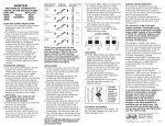
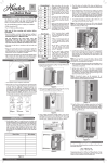
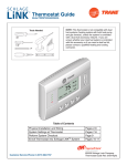
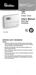
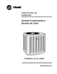
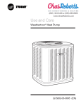
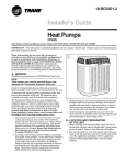
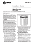
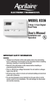
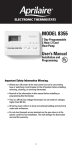
®
Installation of
Hunter® Heat Pump Thermostat
Model 40080
nals to the Hunter terminals. Ignore the color of the wires,
as they do not always match the standard.
Attaching Thermostat to Wall
Heating Anticipation
1.
This thermostat is equipped with fixed anticipators for stage
one heat and cooling which do not require adjustment. Stage 2
(or AUXilliary) heat has an adjustable anticipator.
Additional adjustments, if necessary, may be made as follows:
Heat cycles too long - Set adjustable heater to a slightly lower
dial setting (1/2 division).
Heat cycles too short - Set adjustable heater to a slightly higher
dial setting (1/2 division).
Specifications
2.
Thermal Data
Temperature Range:
Differential:
50°F to 90°F (10°C to 32°C)
Stage 1 Heat - 1 1/4°F
Stage 2 Heat - 0.1 to 1.2 Amps
Cooling - .2 to 1.0 Amp
3.
Electrical Data
Switch Rating:
Switch Action:
Anticipator Rating:
24 volts A.C. (30 VAC max.)
Stage 1 Heat - .2 to 1.2 Amps
Stage 2 Heat - 0.1 to 1.2 Amps
Cooling - .2 to 1.0 Amps
Sealed Mercury Switches
Stage 1 Heat & Cool - SPDT
Stage 2 Heat - SPST
Stage 1 Heat - 24 volts A.C. fixed
Stage 2 Heat - 0.1 to 1.2 Amps adjustable
Cooling - 24 volts A.C. fixed
Safety
This thermostat is a precision instrument, and should be handled
carefully. Rough handling or distorting components could cause
the control to malfunction.
CAUTION: To prevent electrical shock and/or equipment damage, disconnect electric power to system, at main fuse or circuit
breaker box, until installation is complete.
WARNING: Do not use on circuits exceeding 30 volts. Higher
voltage will damage control - could cause shock or fire hazard.
Do not exceed the specification ratings.
Disposal Information
2.
3.
4.
Remove the thermostat cover by carefully pulling outward
until it snaps free.
Carefully remove and discard any packing which protects
the thermometer and the mercury switches during shipment.
If a thermostat is being replaced and it is in a satisfactory
location and the wiring is in good condition, use the existing wiring. If in doubt, have an electrician or HVAC professional replace the wiring.
If replacing an existing thermostat, place enclosed wire labels on each wire to match the terminals on the old thermostat. Refer to the wiring chart to help match the old termiTwo Mounting Holes
Thermostat Cable Opening
Flip-up Lever Terminal Block
Adjustment Second Stage
Lever
Heat Anticipation
The chart shows the different system functions with switches in
various positions. Some models may not have certain system
functions.
SWITCH POSITIONS
Cool
SYSTEM
Off
Heat
Em er Heat
Norm
Em er
SYSTEM FUNCTION
FAN
Auto
On
Fan
Relay
Rev
Valve
3.
4.
Strip wires 1/4 inch.
Raise levers on terminal block. (Accepts 16 awg. stranded,
18-24 awg. sold or stranded)
Place leads into hole in terminal block under appropriate
terminal designation on circuit board and tightly close lever
by pushing downward. (Refer to wiring diagrams for proper
system hook-up.)
Push excess wire into wall or outlet box and plug up the
hole to preven drafts from affecting thermostat operation.
Em er
Heat
Aux
Light
COMPONENT OPERATION
O
Cooling Mode - Compressor contactor and fan relay cycle from
thermostat.
B
Heat Mode - Stage 1 Only - Compressor contactor and fan relay cycle
from thermostat.
B
Heat Mode - Both Stages - Compressor contactor, fan relay, auxiliary
heat relays, and aux. light on.
B
Emergency Heat Mode - Stage 1 Only - Fan and emergency heat relay
energized. Compressor locked out at thermostat. Emer. light on.
B
Emer. Heat Mode - Both Stages - Fan, emergency heat, and auxiliary
heat relays energized. Compressor locked out at thermostat. Emer.
and aux. lights on.
Fan runs continuously regardless of system sw itch position.
O
B
Show s Position of Sw itch and System Function in Operation
Wiring Diagram
Failure to read and follow all instructions carefully, before installing or operating this thermostat, could cause personal injury and/or property damage.
NOTE: The “Y” terminal activates the compressor contactor for
first stage HEAT and first stage COOL.
The changeover relay valve is activated in either the COOLING
or the HEATING mode on all models. By connecting the relay
to the “0” terminal, the relay is activated by moving the system
switch to COOL. By connecting the relay to the “B” terminal the
relay is activated by moving the system to HEAT. Check your
owners manual for the appropriate connection for your system.
Common wire “X” must be connected for proper operation.
GREEN LIGHT (AUXiliary HEAT) - This light indicates auxiliary
heaters are assisting the heat pump in normal system operation. The aux. light will cycle with second stage heat in either
“NORMal HEAT” or “EMERgency HEAT” switch positions.
RED LIGHT (EMERgency HEAT) - This light will glow when the
emergency heat switch has been moved to the “EMER HEAT”
position. DO NOT use this switch for normal heating operations. The switch will bring on electric or gas auxilliary heat and
at the same time prevent the heat pump from operating.
With a jumper installed between “E” and “W2” terminals the
Aux
Heat
Com pr.
Contact
No Heating, No Cooling, No Fan, No Lights.
Attaching Thermostat Wire
1.
2.
Use the chart to check all functions of your thermostat. It explains the operation of your thermostat with the switches in various positions. After checking, your thermostat is now ready for
operation. Set system to desired operations. Set thermostat
temperature lever to the room temperature. It takes at least
one hour after the room temperature has reached the thermostat setting for all sensors to stabilize.
NOTE: In heat pump applications, time delays are involved
before the compressor can be activated to prevent short cycling. The delays are provided by a minimum time off timer in
the heat pump unit which prevents the compressor from starting for up to 5 minutes from when the thermostat last turned the
compressor off, or from the time the system first received power.
For technical support, contact us at 888-830-1326.
Operation and System Check
This product contains mercury in a sealed tube. DO NOT place
this control in the trash at the end of its useful life.
If this product is replacing a control that contains mercury, DO
NOT place the old product in the trash.
Contact your local waste management authority for instructions
regarding recycling and the proper disposal of this product, or
of and for any old control containing mercury in a sealed tube.
Installation
1.
Pull about 4 inches of thermostat wire through the wall opening and lead through the large opening near the center of
the thermostat.
Attach the thermostat directly to the wall with screws and
anchors provided or to a standard horizontal outlet box using the two elongated mounting holes.
Level the thermostat. Use a level placed on top of the thermostat for best results. Minor adjustments can be made
using the elongated holes. Securely tighten mounting
screws.
IMPORTANT: This thermostat was calibrated at true level.
Any inaccuracy in level will cause control point deviation.
Care must be taken to mount the thermostat in a true level
position.
System Operation and Thermostat Check
auxilliary heat strips will be activated for use as emergency heat
strips. See operation chart.
This System Function w ill operate if jumper from E to W2 is connected. (Optional)
Reversing valve energized if connected to "O" terminal
Reversing valve energized if connected to "B" terminal
Wiring Chart and Diagram
Use the chart below to match the wires on your current system or thermostat. Most heat pumps will have connections like one of these.
NOTE: Remove the factory installed jumper if your heat pump has separate wires for E and W2.
Hunter Connection Labels Carrier Colem an Com fortm aker Bryant, Payne Rheem -Ruud Weathertron
R
24 VAC
Y
Compressor
O
Reversing valve - Cool
B
Reversing valve - Heat
York
Lennox (1) Lennox (2)
R
R
R
R
R
R
R
R
V-VR
Y or Y1
Y
Y
Y
Y
Y
Y
Y
M
O
O
O
O
O
R
G
G
G
F
E
E
O
B
B
G
Fan
G
G
G
G
G
E
Emergency Heat
E
E
jumper to W2
E
E
W2
W2
W1
W2
W2
W-U
W
W1
Y
C
X
C
C, C1, X1
X
B
B
C
X
W2 Auxillary Heat
X
Common
Note: W2 & X
w ires no
connection
jumper to W2 jumper to W2
Note: X2 & T
w ires no
connection
Hunter Fan Company
2500 Frisco Avenue
Memphis, Tennessee 38114
© 2002 Hunter Fan Company
41591-01 11/14/2002