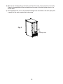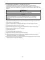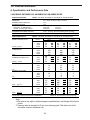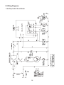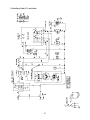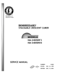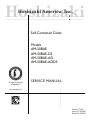
1
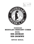
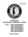
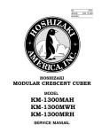
Hoshizaki Hoshizaki America, Inc. Self-Contained Cuber Models AM-50BAE AM-50BAE-DS AM-50BAE-AD AM-50BAE-ADDS “A Superior Degree of Reliability” SERVICE MANUAL www.hoshizaki.com Number: 73126 Issued: 12-22-2004 Revised: 5-23-2013 WARNING Only qualified service technicians should install and service the appliance. To obtain the name and phone number of your local Hoshizaki Certified Service Representative, visit www.hoshizaki.com. No service should be undertaken until the technician has thoroughly read this Service Manual. Failure to service and maintain the appliance in accordance with this manual will adversely affect safety, performance, component life, and warranty coverage and may result in costly water damage. Proper installation is the responsibility of the installer. Product failure or property damage due to improper installation is not covered under warranty. Hoshizaki provides this manual primarily to assist qualified service technicians in the service of the appliance. Should the reader have any questions or concerns which have not been satisfactorily addressed, please call, send an e-mail message, or write to the Hoshizaki Technical Support Department for assistance. Phone: 1-800-233-1940; (770) 487-2331 Fax: 1-800-843-1056; (770) 487-3360 E-mail: [email protected] HOSHIZAKI AMERICA, INC. 618 Highway 74 South Peachtree City, GA 30269 Attn: Hoshizaki Technical Support Department Web Site: www.hoshizaki.com NOTE: To expedite assistance, all correspondence/communication MUST include the following information: • Model Number • Serial Number • Complete and detailed explanation of the problem. 2 IMPORTANT This manual should be read carefully before the appliance is serviced. Read the warnings and guidelines contained in this manual carefully as they provide essential information for the continued safe use, service, and maintenance of the appliance. Retain this manual for any further reference that may be necessary. CONTENTS Important Safety Information.................................................................................................. 4 I. Construction and Water/Refrigeration Circuit Diagram........................................................ 7 A. Construction................................................................................................................... 7 B. Water/Refrigeration Circuit Diagram............................................................................... 8 II. Sequence of Operation and Service Diagnosis.................................................................. 9 A. Sequence of Operation Flow Chart................................................................................ 9 B. Service Diagnosis........................................................................................................ 10 1. Diagnostic Procedure: Auxiliary Code C-0 and Earlier.............................................11 2. Diagnostic Procedure: Auxiliary Code C-1 and Later.............................................. 14 C. Bin Control Check........................................................................................................ 17 D. Thermistor Check......................................................................................................... 18 E. Diagnostic Tables......................................................................................................... 19 III. Control Board................................................................................................................... 22 A. Control Board Layout................................................................................................... 23 1. Auxiliary Code C-0 and Earlier................................................................................ 23 2. Auxiliary Code C-1 and Later.................................................................................. 24 B. Settings and Adjustments............................................................................................. 25 C. LED Lights Auxiliary Code C-1 and Later..................................................................... 26 D. Control Switch.............................................................................................................. 26 IV. Refrigeration Circuit and Component Service Information.............................................. 27 A. Refrigeration Circuit Service Information..................................................................... 27 B. Component Service Information................................................................................... 29 V. Maintenance..................................................................................................................... 30 A. Maintenance Schedule................................................................................................. 30 B. Optional Drain Pump HS-0248 or HS-5061................................................................. 31 VI. Preparing the Icemaker for Periods of Non-Use.............................................................. 33 VII. Disposal.......................................................................................................................... 34 VIII. Technical Information..................................................................................................... 35 A. Specification and Performance Data............................................................................ 35 B. Wiring Diagrams........................................................................................................... 36 1. Auxiliary Code C-0 and Earlier................................................................................ 36 2. Auxiliary Code C-1 and Later.................................................................................. 37 3. HS-0248 and HS-5061 Optional Drain Pump......................................................... 38 3 Important Safety Information Throughout this manual, notices appear to bring your attention to situations which could result in death, serious injury, damage to the appliance, or damage to property. WARNING Indicates a hazardous situation which could result in death or serious injury. NOTICE Indicates a situation which could result in damage to the appliance or property. IMPORTANT Indicates important information about the use and care of the appliance. WARNING The appliance should be destined only to the use for which it has been expressly conceived. Any other use should be considered improper and therefore dangerous. The manufacturer cannot be held responsible for injury or damage resulting from improper, incorrect, and unreasonable use. Failure to service and maintain the appliance in accordance with this manual will adversely affect safety, performance, component life, and warranty coverage and may result in costly water damage. To reduce the risk of death, electric shock, serious injury, or fire, follow basic precautions including the following: • Only qualified service technicians should install and service the appliance. • The appliance must be installed in accordance with applicable national, state, and local codes and regulations. Failure to meet these code requirements could result in death, electric shock, serious injury, fire, or damage. • To reduce the risk of electric shock, do not touch the control switch or plug with damp hands. • Make sure the control switch is in the "OFF" position before plugging in or unplugging the appliance. • Before servicing, move the control switch to the "OFF" position. Unplug the appliance from the electrical outlet. • The appliance requires an independent power supply of proper capacity. See the nameplate for electrical specifications. Failure to use an independent power supply of proper capacity can result in a tripped breaker, blown fuse, damage to existing wiring, or component failure. This could lead to heat generation or fire. • THE APPLIANCE MUST BE GROUNDED: The appliance is equipped with a NEMA 5-15 three‑prong grounding plug to reduce the risk of potential shock hazards. It must be plugged into a properly grounded, independent 3-prong wall outlet. If the outlet is a 2-prong outlet, it is your personal responsibility to have a qualified electrician replace it with a properly grounded, independent 3-prong wall outlet. Do not remove the ground prong from the power cord and do not use an adapter plug. Failure to properly ground the appliance could result in death or serious injury. • The GREEN ground wire in the factory-installed power cord is connected to the appliance. If it becomes necessary to remove or replace the power cord, be sure to connect the power cord's ground wire. 4 WARNING, continued • Do not make any alterations to the appliance. Alterations could result in electric shock, serious injury, fire, or damage. • Do not use an extension cord. • Do not use an appliance with a damaged power cord. The power cord should not be altered, jerked, bundled, weighed down, pinched, or tangled. Such actions could result in electric shock or fire. To unplug the appliance, be sure to pull the plug, not the cord, and do not jerk the cord. • This appliance is not intended for use by persons (including children) with reduced physical, sensory, or mental capabilities, or lack of experience and knowledge, unless they have been given supervision or instruction concerning use of the appliance by a person responsible for their safety. • Children should be properly supervised around this appliance. • Do not climb, stand, or hang on the appliance or appliance door or allow children or animals to do so. Do not climb into the appliance or allow children or animals to do so. Death or serious injury could occur or the appliance could be damaged. • Be careful not to pinch fingers when opening and closing the door. Be careful when opening and closing the door when children are in the area. • Open and close the door with care. Door opened too quickly or forcefully may cause injury or damage to the appliance or surrounding equipment. • Do not use combustible spray or place volatile or flammable substances near the appliance They might catch fire. • Keep the area around the appliance clean. Dirt, dust, or insects in the appliance could cause harm to individuals or damage to the appliance. • Do not place anything on top of the appliance. Foreign objects or moisture could enter the appliance and result in electric shock or fire. 5 NOTICE • Protect the floor when moving the appliance to prevent damage to the floor. • When making water supply or drain line repairs, follow the requirements found in the instruction manual to reduce the risk of costly water damage. • In areas where water damage is a concern, confirm appliance is installed in a contained area with a floor drain. • Confirm the appliance is in a location that stays above freezing. Normal operating ambient temperature must be within 45°F to 100°F (7°C to 38°C). • If using the optional drain pump (HS-0248 or HS-5061), test its operation every time the appliance is cleaned and sanitized. See "V.B. Optional Drain Pump HS-0248 or HS-5061" for details. If the optional drain pump is not operating properly or not primed properly (HS-0248), water could back up and overflow, leading to costly water damage. • If water collects in the bin and will not drain, turn off the appliance and close the water supply line shut-off valve. • If water seeps from the base of the appliance, turn off the appliance and close the water supply line shut-off valve. Failure to do so could lead to costly water damage. • Do not leave the appliance on during extended periods of non-use, extended absences, or in sub-freezing temperatures. To properly prepare the appliance for these occasions, follow the instructions in "VI. Preparing the Appliance for Periods of Non‑Use." • Keep ventilation openings, in the appliance enclosure or in the built-in structure, clear of obstruction. • Do not place objects on top of the appliance. • The ice storage bin is for ice use only. Do not store anything else in the ice storage bin. 6 I. Construction and Water/Refrigeration Circuit Diagram A. Construction Top Panel Ice Making Mechanism Bin Control Thermostat Bulb Scoop Holder Slope Magnet Catch Front Panel Control Switch Door Power Cord Louver 7 B. Water/Refrigeration Circuit Diagram Capillary Tube Accumulator Inlet Water Valve Evaporator Thermistor Ice Chute Spray Assembly Pump Motor Water Tank Ice Storage Bin To Drain Heat Exchanger Hot Gas Valve Condenser Fan Drier Compressor Water Circuit Refrigeration Circuit 8 Strainer 102-sec. WVT 50-sec. HT 1. Initial Harvest Cycle 9 BC open All components de‑energized except BCH and DP All components de-energized. BC closed No ice touching thermostatic bulb. Icemaker starts at "1. Initial Harvest Cycle." 3. Ice Level Lowered BCH continues Comp continues FM de-energized PM de-energized HGV energized WV energized 2. Icemaker Off 50-sec. HT in control Thermistor temperature reaches 45°F (7°C) (4.5 kΩ or less). 50 sec. HT starts. 102-sec. WVT Thermistor in control To 1 above The "WASH" position on the control switch is used when cleaning and sanitizing the icemaker. When in the "WASH" position, power is supplied to the pump motor and fan motor. The cleaner and sanitizer flow over the evaporator plate assembly. If thermistor stays below 27°F (-3°C), 3-min. freeze timer terminates and 5-min FTT starts. Otherwise, 3-min. FT restarts. Legend: BC–bin control BCH–bin control heater Comp–compressor DP–drain pump (optional) FM–fan motor FT–freeze timer FTT–freeze termination timer HGV–hot gas valve HT–harvest timer PM–pump motor WV–inlet water valve WVT–inlet water valve timer 3-min. FT in control Thermistor drops to 27°F (-3°C) (6.8 kΩ or more). 3-min. FT starts. Thermistor in control 5-min. FTT in control • 3-min. FT resets if temperature rises above 27°F (-3°C) during 3-min. FT. BCH continues Comp continues FM energized PM energized HGV de-energized WV de-energized • WV time: 102 sec. or the length of harvest, whichever is shorter. 3. Normal Harvest Cycle 4. Normal Freeze Cycle Components Energized when the Control Switch is in the "WASH" Position Ice contacts thermostatic bulb Within 10 sec. after ice contacts thermostatic bulb, appliance shuts down. 1. Bin Full 5-min. FTT in control If thermistor stays below 27°F (-3°C), 3-min. freeze timer terminates and 5-min FTT starts. Otherwise, 3-min. FT restarts. 3-min. FT in control Thermistor drops to 27°F (-3°C) (6.8 kΩ or more). 3-min. FT starts. WV de-energized 52-sec. Thermistor in control • WV continues for 52 sec. during initial freeze. • 3-min. FT resets if temperature rises above 27°F (-3°C) during 3-min. FT. 2. Initial Freeze Cycle BCH continues Comp continues FM energized PM energized HGV de-energized BC Operation Shutdown and Restart BCH energized Comp energized HGV energized WV energized Startup Cycle Steps AM-50BAE Series Sequence Flow Chart II. Sequence of Operation and Service Diagnosis A. Sequence of Operation Flow Chart B. Service Diagnosis WARNING • The appliance should be diagnosed and repaired only by qualified service personnel to reduce the risk of death, electric shock, serious injury, or fire. • Risk of electric shock. Use extreme caution and exercise safe electrical practices. • Risk of electric shock. Control switch in "OFF" position does not de‑energize all loads (optional drain pump). • Moving parts (e.g., fan blade) can crush and cut. Keep hands clear. • CHOKING HAZARD: Ensure all components, fasteners, and thumbscrews are securely in place after the appliance is serviced. Make sure that none have fallen into the ice storage bin. • Make sure all food zones in the appliance are clean after service. The diagnostic procedure is a sequence check that allows you to diagnose the electrical system and components. Before proceeding, check for correct installation, proper voltage per nameplate, and adequate water supply. Note: • When checking high-voltage (115VAC), always choose a white (W) neutral wire to establish a good neutral connection. • When checking low-voltage (24VAC) (auxiliary code C-1 and later), always choose a light blue (LBU) neutral wire to establish a good neutral connection. • When checking component voltage from CB, pull CB connectors out slightly to allow room for multimeter test leads contact. • BCH energizes at startup and continues until the control switch is turned off or power is disconnected. • Optional drain pump (HS-0248 or HS-5061) has 115VAC power supply as soon as the appliance is plugged into the electrical outlet. 1) Access the control box and move the control switch to the "OFF" position. 2) Clear any ice from BC. 10 1. Diagnostic Procedure: Auxiliary Code C-0 and Earlier 3) Power On/Initial Harvest Cycle. Move the control switch to the "ICE" position. Comp, HGV, and WV energize. Initial harvest cycle starts. 50-sec. HT and 102-sec. WVT start. a) Power On Diagnosis: If Comp, HGV, and WV do not energize, confirm appliance is plugged into electrical outlet. If optional drain pump HS-0248 or HS-5061 is installed, confirm the water level in the drain pump reservoir is not high enough to close the drain pump safety switch. When the water level lowers enough to open the drain pump upper float switch, power is restored to the icemaker. The pump motor remains energized as long as the drain pump lower float switch is closed. If optional drain pump is not installed, check that jumper connection is good. Next, check for 115VAC at control switch #2 (BR) to neutral (W) then at control switch #1 (O) to neutral (W). If 115VAC is present at #2 (BR) to neutral (W) and not at #1 (O) to neutral (W), replace control switch. Check BC continuity. If open, warm BC thermostat bulb with hand. See "II.D. Bin Control Check." If BC does not close, replace BC. If BC is closed and HGV or WV is not energized, check for 115VAC at CB U (BK) to CB V (W). If 115VAC is not present, check wiring. If 115VAC is present, see "d) HGV Diagnosis" or "e) WV Diagnosis" below. b) BCH Diagnosis: If BCH does not energize, check BCH continuity. If open, replace BCH. c) Comp Diagnosis: If Comp does not energize, check PTC relay continuity. If open, replace PTC. If closed, check Comp external protector and motor winding continuity. Replace as needed. d) HGV Diagnosis: If Comp is energized and evaporator is not warming, check that HGV energizes and opens. If not, check for 115VAC at CB C1 (BK) to neutral (W) and at CB B1 (P) to neutral (W). If 115VAC is present at CB C1 (BK) to neutral (W) and not at CB B1 (P) to neutral (W), replace CB. If 115VAC is not present at CB C1 (BK), check wiring connections from BC. If 115VAC is present, check HGV coil continuity. Replace as needed. e) WV Diagnosis: Check that water enters the water tank. If not, check that the water supply line shut‑off valve is open and screens or external filters are clear. Check for 115VAC at CB C2 (BK) to neutral (W) and CB A2 (V) to neutral (W). If 115VAC is not present at CB C2 (BK), check wiring from BC. If 115VAC is present at CB C2 (BK) to neutral (W) and not at CB A2 (V) to neutral (W), replace CB. If 115VAC is present and WV does not energize, check WV coil continuity. If open, replace WV. f) Initial Harvest Cycle Termination Diagnosis: 50-sec. HT terminates and freeze cycle starts. If not, replace CB. 11 4) Initial Freeze Cycle. Comp and 102-sec. WVT (WV continues another 52 sec. in freeze cycle) continue. FM and PM energize. HGV de-energizes. When 102-sec. WVT terminates, WV de-energizes. CB monitors the cooling of the evaporator via the thermistor located on the evaporator for freeze termination. When the thermistor drops to 27°F (-3°C), CB reads 6.8 kΩ from the thermistor and starts 3-min. FT. 27°F (-3°C) or lower must be maintained the entire 3 min. If reading rises above 27°F (-3°C) before 3-min. FT terminates, 3-min. FT resets. When 27°F (-3°C) or lower is maintained for 3 min., 5-min. FTT starts. a) Comp Diagnosis: If Comp de-energizes, check PTC relay continuity. If open, replace PTC. If closed, check Comp external protector and motor winding continuity. Replace as needed. If Comp is energized but evaporator is not cooling, check for an inefficient Comp. See "VIII.B. Performance Data." b) FM and PM Diagnosis: If FM and PM do not energize, check for 115VAC at CB B1 (P) to neutral (W) and CB A1 (LBU) to neutral (W). If 115VAC is present at CB B1 (P) to neutral (W) and not at CB A1 (LBU) to neutral (W), replace CB. If 115VAC is present at CB A1 (LBU) to neutral (W), check FM or PM motor winding continuity, fan blade or PM impeller for binding, and PM capacitor. c) HGV and WV Diagnosis: Confirm HGV and WV de-energize. If HGV is energized, check for 115VAC at CB B1 (P) to neutral (W). If 115VAC is present after PM energizes, replace CB. If 115VAC is not present and HGV is bypassing, replace HGV. If WV does not de-energize 52 sec. after freeze cycle starts, check for 115VAC at CB A2 (V) to neutral (W). If 115VAC is present 52 sec. or later after PM energizes, replace CB. If 115VAC is not present and WV is leaking by, replace WV. d) Initial Freeze Cycle Termination Diagnosis: 5-min. FTT terminates, harvest cycle starts. If not, check evaporator temperature where thermistor is mounted and check the thermistor. See "II.E. Thermistor Check." If evaporator temperature is below 27°F (-3°C) for more than 8 min. and freeze does not terminate, replace CB. 5) Normal Harvest Cycle. Comp continues. HGV and WV energize. FM and PM de‑energize. 102-sec. WV timer starts. CB monitors the warming of the evaporator via the thermistor located on the evaporator. When the thermistor reaches 47°F (7°C), CB reads 4.5 kΩ from the thermistor and turns harvest termination over to the 50-sec. HT. WV is energized during harvest for a maximum of 102 sec. or the length of harvest, whichever is shorter. Note: Appliance continues to cycle until BC is satisfied or power is turned off. The appliance always restarts at the initial harvest cycle. a) Comp Diagnosis: Check that evaporator is warming. If not, confirm Comp is energized. If not, check for 115VAC at PTC and check PTC relay continuity. If open, replace PTC. If closed, check Comp external protector and motor winding continuity. Replace as needed. b) HGV Diagnosis: If Comp is energized and evaporator is not warming, check that HGV energizes and opens. If not, check for 115VAC at CB C1 (BK) to neutral (W) and at CB B1 (P) to neutral (W). If 115VAC is present at CB C1 (BK) to neutral (W) and not at CB B1 (P) to neutral (W), replace CB. If 115VAC is not present at CB C1 (BK) to neutral (W), check wiring connections from BC. If 115VAC is present, check HGV coil continuity. Replace as needed. 12 c) WV Diagnosis: Check that water enters the water tank. If not, check that the water supply line shut‑off valve is open and screens or external filters are clear. Check for 115VAC at CB C2 (BK) to neutral (W) and CB A2 (V) to neutral (W). If 115VAC is not present at CB C2 (BK) to neutral (W), check wiring from BC. If 115VAC is present at CB C2 (BK) to neutral (W) and not at CB A2 (V) to neutral (W), replace CB. If 115VAC is present and WV does not energize, check WV coil continuity. If open, replace WV. d) FM and PM Diagnosis: Confirm FM and PM de-energize. If not, check for 115VAC at CB A1 (LBU) to neutral (W) and CB B1 (P) to neutral (W). If 115VAC is present at CB A1 (LBU) and not at CB B1 (P), CB is still in freeze cycle or CB X1 relay is sticking. Replace as needed. e) Normal Harvest Cycle Termination Diagnosis: For a thermistor check, see "II.D. Thermistor Check." If evaporator is warming, thermistor reading is correct, and harvest does not terminate, replace CB. 6) Normal Freeze Cycle. Comp continues. FM and PM energize. HGV and WV de‑energize. CB monitors the cooling of the evaporator via the thermistor located on the evaporator for freeze termination. When the thermistor drops to 27°F (-3°C), CB reads 6.8 kΩ from the thermistor and starts 3-min. FT. 27°F (-3°C) or lower must be maintained the entire 3 min. If reading rises above 27°F (-3°C) before 3-min. FT terminates, 3-min. FT resets. When 27°F (-3°C) or lower is maintained for 3 min., 5-min. FTT starts. a) Comp Diagnosis: If Comp de-energizes, check PTC relay continuity. If open, replace PTC. If closed, check Comp external protector and motor winding continuity. Replace as needed. If Comp is energized but evaporator is not cooling, check for an inefficient Comp. See "VIII.B. Performance Data." b) FM and PM Diagnosis: If FM and PM do not energize, check for 115VAC at CB B1 (P) to neutral (W) and CB A1 (LBU) to neutral (W). If 115VAC is present at CB B1 (P) to neutral (W) and not at CB A1 (LBU) to neutral (W), replace CB. If 115VAC is present at CB A1 (LBU) to neutral (W), check FM or PM motor winding continuity, fan blade or PM impeller for binding, and PM capacitor. c) HGV and WV Diagnosis: Confirm HGV and WV de-energize. If HGV is energized, check for 115VAC at CB B1 (P) to neutral (W). If 115VAC is present after PM energizes, replace CB. If 115VAC is not present and HGV is bypassing, replace HGV. If WV is energized, check for 115VAC at CB A2 (V) to neutral (W). If 115VAC is present, replace CB. If 115VAC is not present and WV is leaking by, replace WV. d) Normal Freeze Cycle Termination Diagnosis: 5-min. FTT terminates, harvest cycle starts. If not, check evaporator temperature where thermistor is mounted and check the thermistor. See "II.E. Thermistor Check." If evaporator temperature is below 27°F (-3°C) for more than 8 min. and freeze does not terminate, replace CB. 7) Shutdown. When the appliance is running, hold ice in contact with the thermostatic bulb. BC switch opens within 10 sec., shutting down the appliance. BC is factory set and generally no adjustment is required. However, adjustment may be needed in some conditions, particularly at higher altitude locations. Legend: BC–bin control; CB–control board; Comp–compressor; FM–fan motor; FT–freeze timer; FTT–freeze termination timer; HGV–hot gas valve; HT–harvest timer; PM–pump motor; WV–inlet water valve; WVT–inlet water valve timer 13 2. Diagnostic Procedure: Auxiliary Code C-1 and Later 3) Power On/Initial Harvest Cycle – LED 1 is flashing and LED 3 is on. Move the control switch to the "ICE" position. LEDs 1 (green), 3 (green), and 4 (orange) turn on briefly then turn off. Then LED 1 starts flashing, LED 3 turns on and Comp, HGV, and WV energize. Initial harvest cycle starts. 50-sec. HT and 102-sec. WVT start. Note: 24VAC to CB is confirmed with a flashing LED 1. a) Power On Diagnosis: Confirm green LED 1 is flashing. If not, confirm appliance is plugged into electrical outlet. If optional drain pump HS-0248 or HS‑5061 is installed, confirm the water level in the drain pump reservoir is not high enough to close the drain pump safety switch. When the water level lowers enough to open the drain pump upper float switch, power is restored to the icemaker. The pump motor remains energized as long as the drain pump lower float switch is closed. If optional drain pump is not installed, check that jumper connection is good. Next, check for 115VAC at control switch #2 (BR) to neutral (W) then at control switch #1 (BR) to neutral (W). If 115VAC is present at #2 (BR) to neutral (W) and not at #1 (BR) to neutral (W), replace control switch. Check BC continuity. If open, warm BC thermostat bulb with hand. See "II.D. Bin Control Check." If BC does not close, replace BC. If BC is closed and LED 1 is not flashing, check for 115VAC primary voltage and 24VAC secondary voltage at CT. If 115VAC is present and 24VAC is not, replace CT. If 24VAC is present, check for 24VAC at CB B (R) to CB W (LBU). If 24VAC is not present, check low-voltage wiring. If 24VAC is present and LED 1 is not on and flashing, replace CB. b) BCH Diagnosis: If BCH does not energize, check BCH continuity. If open, replace BCH. c) Comp Diagnosis: If Comp does not energize, check PTC relay continuity. If open, replace PTC. If closed, check Comp external protector and motor winding continuity. Replace as needed. d) HGV Diagnosis: If Comp is energized and evaporator is not warming, check that HGV energizes and opens. If not, check for 115VAC at CB C1 (BR) to neutral (W) and at CB B1 (P) to neutral (W). If 115VAC is present at CB C1 (BR) to neutral (W) and not at CB B1 (P) to neutral (W), replace CB. If 115VAC is not present at CB C1 (BR) to neutral (W), check wiring connections from BC. If 115VAC is present, check HGV coil continuity. Replace as needed. e) WV Diagnosis: Confirm LED 3 is on. If not, replace CB. If LED 3 is on, check that water enters the water tank. If not, check that the water supply line shut‑off valve is open and screens or external filters are clear. Check for 115VAC at CB C2 (BR) to neutral (W) and CB A2 (O) to neutral (W). If 115VAC is not present at CB C2 (BR) to neutral (W), check wiring from BC. If 115VAC is present at CB C2 (BR) to neutral (W) and not at CB A2 (O) to neutral (W), replace CB. If 115VAC is present and WV does not energize, check WV coil continuity. If open, replace WV. f) Initial Harvest Cycle Termination Diagnosis: 50-sec. HT terminates and freeze cycle starts. If not, replace CB. 14 4) Initial Freeze Cycle – LED 1 is flashing and LEDs 3 and 2 are on. Comp and 102-sec. WVT (WV continues another 52 sec. in freeze cycle) continue. FM and PM energize. HGV de‑energizes. When 102-sec. WVT terminates, LED 3 turns off and WV de-energizes. CB monitors the cooling of the evaporator via the thermistor located on the evaporator for freeze termination. When the thermistor drops to 27°F (-3°C), CB reads 6.8 kΩ from the thermistor and starts 3-min. FT. 27°F (-3°C) or lower must be maintained the entire 3 min. If reading rises above 27°F (-3°C) before 3-min. FT terminates, the 3-min. FT resets. When 27°F (-3°C) or lower is maintained for 3 min., 5-min. FTT starts. a) Comp Diagnosis: If Comp de-energizes, check PTC relay continuity. If open, replace PTC. If closed, check Comp external protector and motor winding continuity. Replace as needed. If Comp is energized but evaporator is not cooling, check for an inefficient Comp. See "VIII.B. Performance Data." b) FM and PM Diagnosis: If FM and PM do not energize, check for 115VAC at CB B1 (P) to neutral (W) and at CB A1 (DBU) to neutral (W). If 115VAC is present at CB B1 (P) to neutral (W) and not at CB A1 (DBU) to neutral (W), replace CB. If 115VAC is present at CB A1 (DBU) to neutral (W), check FM or PM motor winding continuity, fan blade or PM impeller for binding, and PM capacitor. c) HGV and WV Diagnosis: Confirm HGV and WV de-energize. If HGV is energized, check for 115VAC at CB B1 (P) to neutral (W). If 115VAC is present after PM energizes, replace CB. If 115VAC is not present and HGV is bypassing, replace HGV. If LED 3 does not turn off and WV does not de-energize 52 sec. after freeze cycle starts, check for 115VAC at CB A2 (O) to neutral (W). If 115VAC is present 52 sec. or later after PM energizes, replace CB. If 115VAC is not present and WV is leaking by, replace WV. d) Initial Freeze Cycle Termination Diagnosis: 5-min. FTT terminates, harvest cycle starts. If not, check evaporator temperature where thermistor is mounted and check the thermistor. See "II.E. Thermistor Check." If evaporator temperature is below 27°F (-3°C) for more than 8 min. and freeze does not terminate, replace CB. 5) Normal Harvest Cycle – LED 1 is flashing and LED 3 is on. Comp continues. HGV and WV energize. FM and PM de‑energize. 1 02-sec. WV timer starts. CB monitors the warming of the evaporator via the thermistor located on the evaporator. When the thermistor reaches 47°F (7°C), CB reads 4.5 kΩ from the thermistor and turns harvest termination over to the 50-sec. HT. WV is energized during harvest for a maximum of 102 sec. or the length of harvest, whichever is shorter. Note: Appliance continues to cycle until BC is satisfied or power is turned off. The appliance always restarts at the initial harvest cycle. a) Comp Diagnosis: Check that evaporator is warming. If not, confirm Comp is energized. If not, check for 115VAC at PTC and check PTC relay continuity. If open, replace PTC. If closed, check Comp external protector and motor winding continuity. Replace as needed. 15 b) HGV Diagnosis: If Comp is energized and evaporator is not warming, check that HGV energizes and opens. If not, check for 115VAC at CB C1 (BR) to neutral (W) and CB B1 (P) to neutral (W). If 115VAC is present at CB C1 (BR) to neutral (W) and not at CB B1 (P) to neutral (W), replace CB. If 115VAC is not present at CB C1 (BR) to neutral (W), check wiring connections from BC. If 115VAC is present, check HGV coil continuity. Replace as needed. c) WV Diagnosis: Confirm LED 3 is on. If not, replace CB. If LED 3 is on, check that water enters the water tank. If not, check that the water supply line shut‑off valve is open and screens or external filters are clear. Check for 115VAC at CB C2 (BR) to neutral (W) and CB A2 (O) to neutral (W). If 115VAC is not present at CB C2 (BR) to neutral (W), check wiring from BC. If 115VAC is present at CB C2 (BR) to neutral (W) and not at CB A2 (O) to neutral (W), replace CB. If 115VAC is present and WV does not energize, check WV coil continuity. If open, replace WV. d) FM and PM Diagnosis: If FM and PM continue after LED 2 turns off, replace CB. e) Normal Harvest Cycle Termination Diagnosis: For a thermistor check, see "II.D. Thermistor Check." If evaporator is warming, thermistor reading is correct, and harvest does not terminate, replace CB. 6) Normal Freeze Cycle – LED 1 is flashing and LED 2 is on. Comp continues. FM and PM energize. HGV and WV de‑energize. CB monitors the cooling of the evaporator via the thermistor located on the evaporator for freeze termination. When the thermistor drops to 27°F (-3°C), CB reads 6.8 kΩ from the thermistor and starts 3-min. FT. 27°F (-3°C) or lower must be maintained the entire 3 min. If reading rises above 27°F (-3°C) before 3-min. FT terminates, 3-min. FT resets. When 27°F (-3°C) or lower is maintained for 3 min., 5-min. FTT starts. a) Comp Diagnosis: If Comp de-energizes, check PTC relay continuity. If open, replace PTC. If closed, check Comp external protector and motor winding continuity. Replace as needed. If Comp is energized but evaporator is not cooling, check for an inefficient Comp. See "VIII.A. Specification and Performance Data." b) FM and PM Diagnosis: If FM and PM do not energize, check for 115VAC at CB B1 (P) to neutral (W) and CB A1 (DBU) to neutral (W). If 115VAC is present at CB B1 (P) to neutral (W) and not at CB A1 (DBU) to neutral (W), replace CB. FM-If 115VAC is present at CB A1 (DBU) to neutral (W), check FM or PM motor winding continuity, fan blade or PM impellar for binding and PM capacitor. c) HGV and WV Diagnosis: Confirm HGV and WV de-energize. If HGV is energized, check for 115VAC at CB B1 (P) to neutral (W). If 115VAC is present after PM energizes, replace CB. If 115VAC is not present and HGV is bypassing, replace HGV. If LED 3 is on after LED 2 turns on, replace CB. When LED 3 turns off, make sure WV is not leaking by. If WV is leaking by, replace WV. d) Normal Freeze Cycle Termination Diagnosis: 5-min. FTT terminates, harvest cycle starts. If not, check evaporator temperature where thermistor is mounted and check the thermistor. See "II.E. Thermistor Check." If evaporator temperature is below 27°F (-3°C) for more than 8 min. and freeze does not terminate, replace CB. 16 7) Shutdown. When the appliance is running, hold ice in contact with the thermostatic bulb. BC switch opens within 10 sec., shutting down the appliance. BC is factory set, and generally no adjustment is required. However, adjustment may be needed in some conditions, particularly at higher altitude locations. Legend: BC–bin control; CB–control board; Comp–compressor; FM–fan motor; FT–freeze timer; FTT–freeze termination timer; HGV–hot gas valve; HT–harvest timer; PM–pump motor; WV–inlet water valve; WVT–inlet water valve timer C. Bin Control Check BC shuts down the icemaker within 10 sec. when ice contacts the thermostatic bulb, regardless of the cycle at activation. NOTICE When the ambient temperature is below 45°F (7°C), BC opens and shuts down the appliance even if the ice storage bin is empty. To check BC, follow the steps below. 1) Move the control switch to the "OFF" position. 2) Unplug the appliance. 3) Remove the control box cover. Loosen the control box from the base and slide it out for easy access. Next, clear any ice away from BC bulb. 4) Use the wiring diagram to locate the 2 wires supplied to BC. Disconnect BC wires. 5) Hold your hand around the bulb to warm it up. 6) Check for continuity across BC wires. If closed, continue to step 7. If open, replace BC. 7) With the multimeter test leads still in place, hold ice in contact with BC bulb. BC should open within 10 sec. If not, BC must be adjusted. Installations at higher altitude locations are more likely to require adjustment. If BC will not shut down the appliance even after being adjusted, replace BC. Legend: BC–bin control 17 D. Thermistor Check To check thermistor resistance, follow the steps below. 1) Move the control switch to the "OFF" position. 2) Unplug the appliance. 3) Remove the control box cover. 4) Remove the thermistor from the evaporator. 5) Immerse the thermistor sensor portion in a glass containing ice and water for 2 or 3 min. 6) Disconnect the thermistor connector from CB and check the resistance between thermistor leads. Normal range is 5.5 to 6.5 kΩ. If outside the normal range, replace the thermistor. See "IV.B. Important Notes for Component Replacement." If within the normal range, continue to the next step. 7) Replace the thermistor in its correct position. See "IV.B. Important Notes for Component Replacement." 8) Reconnect the thermistor connector to CB. 9) Replace the control box cover in its correct position. 10) Plug the appliance back into the electrical outlet. 11) Move the control switch to the "ICE" position. Legend: CB–control board; Comp–compressor 18 E. Diagnostic Tables 1. No Ice Production No Ice Production - Possible Cause 1. Power Supply a) Unplugged, off, blown fuse, or tripped breaker. b) Not within specifications. 2. Water Supply a) Water supply off or improper water pressure. b) External water filters clogged. 3. Optional Drain Pump (HS-0248 or HS-5061) a) Safety switch open. b) Connector loose or disconnected. c) Clogged or kinked hose. d) Defective. 4. Control Switch a) In "OFF" or "WASH" position. b) Bad contacts. 5. Thermostatic Bin Control See "II.C. Bin Control Check" a) Out of adjustment. b) Open with bin filled with ice. c) Ambient temperature too cool. d) Bulb out of position. e) Bin control heater defective. f) Defective. 6. Control Transformer (115VAC/24VAC) (Auxiliary Code C-1 and Later) a) Defective. 7. Control Board a) Defective. 8. Compressor a) External protector defective. b) PTC defective. c) Inefficient. d) Open windings. 9. Inlet Water Valve a) Screen or orifice clogged. b) Coil winding open. c) Inlet water valve remains open longer than 52 sec. in initial freeze cycle or remains open in normal freeze cycle. 10. Hot Gas Valve a) Closed in harvest cycle. b) Open in freeze cycle. 11. Inlet Water Valve a) Screen or orifice clogged. b) Coil winding open. c) Water valve open in freeze cycle. 12. Hot Gas Valve a) Closed in harvest cycle. b) Open in freeze cycle. 13. Thermistor See "II.E. Thermistor Check" a) Loose, disconnected, or defective. 14. Pump Motor a) Motor winding open. b) Bearing worn out or locked rotor. c) Defective capacitor. 15. Fan Motor a) Motor winding open. b) Bearing worn out or locked rotor. 19 2. Freeze-Up Defrost and clean the icemaker prior to diagnosing freeze-up. Fill out a freeze-up checklist. See the Hoshizaki America Technician's Pocket Guide or contact your local distributor for a copy of the freeze-up checklist. Freeze-Up - Possible Cause Harvest Cycle 1. Evaporator a) Scaled up. b) Damaged. 2. Ice Chute a) Out of position. b) Damaged. 3. Control Board See "III.B. Settings and Adjustments." a) Harvest control set too short. Do not adjust. 4. Bin Control See "II.C. Bin Control Check" a) Bin control heater defective. 5. Thermistor See "II.D. Thermistor Check" a) Loose, disconnected, or defective. 6. Refrigerant Charge a) Low. 7. Hot Gas Valve a) Closed or restricted. b) Freeze control set too long. c) Defective. b) Defective. Freeze Cycle 1. Evaporator a) Scaled up. b) Damaged. 2. Spray Assembly a) Nozzles dirty. b) Ice chute out of position. 3. Control Board See "III.B. Settings and Adjustments." a) Freeze control set incorrectly. 4. Thermistor See "II.E. Thermistor Check" a) Defective. 5. Refrigerant Charge a) Low. 6. Inlet Water Valve a) Leaking by. 7. Pump Motor a) RPM too slow. b) Defective. b) Impeller damaged. 20 3. Low Ice Production Low Ice Production - Possible Cause Long Harvest Cycle 1. Evaporator a) Scaled up, dirty. 2. Ice Chute a) Out of position. b) Damaged. 3. Refrigerant Charge a) Low. 4. Control Board See "III.B. Settings and Adjustments." a) Thermistor connection loose. 5. Thermistor See "II.E. Thermistor Check" a) Loose, disconnected, or defective. 6. Hot Gas Valve a) Erratic or closed. 7. Inlet Water Valve a) Screen or orifice clogged. 8. Compressor a) Inefficient or off. b) Harvest control moved from factory setting. c) Defective. Long Freeze Cycle 1. Evaporator a) Scaled up, dirty. 2. Inlet Water Valve a) Leaking by. 3. Hot Gas Valve a) Erratic or open. 4. Condenser a) Clogged. 5. Thermistor See "II.E. Thermistor Check" a) Loose, disconnected, or defective. 6. Control Board See "III.B. Settings and Adjustments." a) Freeze control set too long. 7. Refrigerant Charge a) Low. 8. Compressor a) Inefficient or off. 9. Pump Motor a) RPM too slow. b) Defective. 21 III. Control Board • A Hoshizaki exclusive control board is employed in AM series appliances. • All models are pretested and factory adjusted. NOTICE • Fragile, handle very carefully. • The control board contains integrated circuits, which are susceptible to failure due to static discharge. It is especially important to touch the metal part of the icemaker when handling or replacing the control board. • Do not touch the electronic devices on the control board or the back of the control board. • Do not change wiring and connections. • Do not short out power supply to test for voltage. • Always replace the whole control board assembly if it goes bad. 22 A. Control Board Layout 1. Auxiliary Code C-0 and Earlier • B1 Connector Hot Gas Valve • C1 Connector 115VAC X1 Relay Component Power Supply (hot gas valve, pump motor, fan motor) • A1 Connector Pump Motor Fan Motor • X1 Relay Hot Gas Valve Pump Motor Fan Motor • C2 Connector 115VAC X2 Relay Component Power Supply (inlet water valve) • A2 Connector Inlet Water Valve • X2 Relay Inlet Water Valve • Control Transformer • Freeze Control • Harvest Control Do not adjust • TH1 Connector Thermistor • TH2 Connector Thermistor 23 • 115VAC Control Board Power Supply U–115VAC Control Board Power Supply (BK) V–Neutral (W) 2. Auxiliary Code C-1 and Later • B1 Connector Hot Gas Valve • C1 Connector 115VAC X1 Relay Component Power Supply (hot gas valve, pump motor, and fan motor) • A1 Connector Pump Motor Fan Motor • C2 Connector 115VAC X2 Relay Component Power Supply (inlet water valve) • X1 Relay Hot Gas Valve Pump Motor Fan Motor • A2 Connector Inlet Water Valve LED 2 • LED 2 Pump Motor Fan Motor LED 3 • X2 Relay Inlet Water Valve • LED 3 Hot Gas Valve LED 1 • LED 1 (flashes) 24VAC Power OK COLD WARM • Freeze Control COLD WARM • 24VAC Control Board Power Supply B–24VAC Control Board Power Supply (R) W–Neutral (LBU) • Harvest Control Do not adjust • TH1 Connector Thermistor • TH2 Connector Thermistor 24 B. Settings and Adjustments 1) VR1 Harvest Control VR1 harvest control is for adjustment of the harvest cycle completion temperature. Factory set, do not adjust. NOTICE Do not adjust VR1 harvest control. VR1 harvest control is factory set for proper operation. Adjustment outside of the factory default setting will result in freeze up and/or damage to the appliance. a) Initial Harvest: Terminated by 50 sec. harvest timer. No temperature requirement. b) Normal Harvest: Terminated by temperature (47°F (7°C)) and time (50 sec. harvest timer). Once the thermistor warms to 47°F (7°C), CB reads 4.5 kΩ from the thermistor and turns harvest termination over to the 50-sec. harvest timer. 2) VR2 Freeze Control VR2 freeze control is for adjustment of the freeze cycle completion temperature (controls size of hole in ice cube). If adjustment to cube hole size is desired, follow the instructions below. See Fig. 1. NOTICE Do not adjust VR2 to the lowest temperature setting. This will result in freeze up. a) Larger Hole: Turn VR2 freeze control clockwise for a higher freeze cycle completion temperature (WARM) for shorter freeze time and ice cubes with larger diameter holes. b) Smaller Hole: Turn VR2 freeze control counterclockwise for a lower freeze cycle completion temperature (COLD) for longer freeze time and ice cubes with smaller diameter holes. Control Board Freeze Control Adjustment of freeze cycle completion temperature Harvest Control Do not adjust COLD COLD WARM WARM LED 1 Fig. 1 25 C. LED Lights Auxiliary Code C-1 and Later 1) LED 1 24VAC Green LED 1 flashes to indicate proper 24VAC and continues to flash unless BC is open, control switch is moved to the "OFF" position, or appliance is unplugged. 2) LED 2 Freeze Green LED 2 (PM) turns on at freeze cycle initiation and turns off at freeze cycle termination. 3) LED 3 Harvest Green LED 3 (HGV) turns on at harvest cycle initiation and turns off at harvest cycle termination. D. Control Switch The control switch has three positions: "OFF," "ICE," and "WASH." In the "OFF" position power is still present at the DP connector and DP (if applicable). In the "WASH" position, PM and FM energize after the 50 sec. HT terminates (C-0 and earlier). Note: When in the "WASH" position, FM also energizes. Legend: BC–bin control; DP–drain pump; HGV–hot gas valve; HT–harvest timer; FM–fan motor; PM–pump motor 26 IV. Refrigeration Circuit and Component Service Information WARNING • This appliance should be diagnosed and repaired only by qualified service personnel to reduce the risk of death, electric shock, serious injury, or fire. • Move the control switch to the "OFF" position, then unplug the appliance from the electrical outlet before servicing. • CHOKING HAZARD: Ensure all components, fasteners, and thumbscrews are securely in place after the icemaker is serviced. Make sure that none have fallen into the ice storage bin. • Make sure all food zones in the icemaker and ice storage bin are clean after service. A. Refrigeration Circuit Service Information WARNING • Repairs requiring the refrigeration circuit to be opened must be performed by properly trained and EPA-certified service personnel. • Use an electronic leak detector or soap bubbles to check for leaks. Add a trace of refrigerant to the system (if using an electronic leak detector), and then raise the pressure using nitrogen gas (140 PSIG). Do not use R‑134a as a mixture with pressurized air for leak testing. NOTICE • Always recover the refrigerant and store it in an approved container. Do not discharge the refrigerant into the atmosphere. • Do not leave the system open for longer than 15 min. when replacing or servicing parts. The Polyol Ester (POE) oils used in R-134a applications can absorb moisture quickly. Therefore it is important to prevent moisture from entering the system when replacing or servicing parts. • Always install a new drier every time the sealed refrigeration system is opened. Do not replace the drier until after all other repair or replacement has been made. Install the new drier with the arrow on the drier in the direction of the refrigerant flow. • When brazing, protect the drier by using a wet cloth to prevent the drier from overheating. Do not allow the drier to exceed 250°F (121°C). 1. Refrigerant Recovery No refrigerant access valves are provided on this appliance. Using proper refrigerant practices, utilize a temporary tap-line valve on the high side to recover the refrigerant. Store the refrigerant in an approved container. Do not discharge the refrigerant into the atmosphere. After recovery is complete, replace the tap-line valve with a proper, permanent access valve. 27 2. Brazing WARNING • R-134a itself is not flammable at atmospheric pressure and temperatures up to 212°F (100°C). • R-134a itself is not explosive or poisonous. However, when exposed to high temperatures (open flames), R-134a can be decomposed to form hydrofluoric acid and carbonyl fluoride both of which are hazardous. • Do not use silver alloy or copper alloy containing arsenic. 1) Braze all fittings while purging with nitrogen gas flowing at a pressure of 3 to 4 PSIG. NOTICE • Always install a new drier every time the sealed refrigeration system is opened. • Do not replace the drier until after all other repair or replacement has been made. Install the new drier with the arrow on the drier in the direction of the refrigerant flow. • When brazing, protect the drier by using a wet cloth to prevent the drier from overheating. Do not allow the drier to exceed 250°F (121°C). 2) Use an electronic leak detector or soap bubbles to check for leaks. Add a trace of refrigerant to the system (if using an electronic leak detector), and then raise the pressure using nitrogen gas (140 PSIG). Do not use R-134a as a mixture with pressurized air for leak testing. 3. Evacuation and Recharge (R-134a) 1) Attach a vacuum pump to the system. Be sure the high-side charging hose is connected to the field-installed high-side access valve. IMPORTANT The vacuum level and vacuum pump may be the same as those for current refrigerants. However, the rubber hose and gauge manifold to be used for evacuation and refrigerant charge should be exclusively for POE oils. 2) Turn on the vacuum pump. Open the gauge manifold valves. Never allow the oil in the vacuum pump to flow backwards. 3) Allow the vacuum pump to pull down to a 29.9" Hg vacuum. Evacuating period depends on pump capacity. 4) Close the high-side valve on the gauge manifold. 5) Disconnect the gauge manifold hose from the vacuum pump and attach it to a refrigerant service cylinder. Remember to loosen the connection and purge the air from the hose. For the required refrigerant charge, see the rating label inside the icemaker. Hoshizaki recommends only virgin refrigerant or reclaimed refrigerant which meets ARI Standard 700 (latest edition) be used. 28 6) A liquid charge is recommended when charging an R-134a system. Place the service cylinder on the scales; if the service cylinder is not equipped with a dip tube, invert the service cylinder, then place it on the scales. Open the high-side valve on the gauge manifold. 7) Allow the system to charge with liquid until the proper charge weight is met. 8) Close the high-side valve on the gauge manifold, then close the refrigerant access valve (if applicable). Disconnect the gauge manifold hose. 9) Cap the access valve to prevent a possible leak. B. Component Service Information NOTICE When replacing a component listed below, see the notes to help ensure proper operation. Component Notes Compressor Install a new drier and PTC relay. Hot Gas Valve • Replace the strainer. • Use copper tube of the same diameter and length when replacing valve lines. Pump Motor Install a new capacitor. Thermistor • Attach the new thermistor to the evaporator in the same location as the previous thermistor. • Smoothly fill the recessed area of the thermistor holder with high thermal conductive type sealant. Hoshizaki America part number 4A0683-01 (Silicone Heat Sink Compound 10-8108 manufactured by GC Electronics), KE-4560 RTV (manufactured by ShinEtsu Silicones), or equivalent are recommended. • Secure the thermistor with the holder. • Be very careful to prevent damage to the leads. 29 V. Maintenance This appliance must be maintained in accordance with the instruction manual and labels provided with the appliance. Consult with your local Hoshizaki Certified Service Representative about maintenance service. WARNING • Only qualified service technicians should service this appliance. • Failure to install, operate, and maintain the appliance in accordance with this manual will adversely affect safety, performance, component life, and warranty coverage. • Move the control switch to the "OFF" position and unplug the appliance from the electrical outlet before servicing. • To reduce the risk of electric shock, do not touch the control switch or plug with damp hands. • CHOKING HAZARD: Ensure all components, fasteners, and thumbscrews are securely in place after any maintenance is performed. Make sure that none have fallen into the ice storage bin. • After service, make sure that there are no wires pinched between the panels and appliance. Make sure you do not damage or pinch the water supply line, drain line, or power cord. A. Maintenance Schedule The maintenance schedule below is a guideline. More frequent maintenance may be required depending on water quality, the appliance's environment, and local sanitation regulations. Maintenance Schedule Frequency Area Task Weekly Monthly Clean the scoop using a neutral cleaner. Rinse thoroughly after cleaning. Check for proper pressure and change if necessary. Every 3 Months Yearly Scoop External Water Filters Appliance Exterior Ice Storage Bin Drain Appliance and Ice Storage Bin Optional Drain Pump (HS-0248 or HS-5061) Water Supply Inlet Condenser Water Hoses Wipe down with clean, soft cloth. Use a damp cloth containing a neutral cleaner to wipe off oil or dirt build up. Clean any chlorine staining (rust colored spots) using a non-abrasive cleaner like Zud or Bon Ami. Maintain as outlined in the instruction manual or maintenance label. Clean and sanitize per the cleaning and sanitizing instructions provided in the instruction manual. Test as outlined in "V.B. Optional Drain Pump HS-0248 or HS-5061." Close the icemaker water supply line shut‑off valve and drain the water system. Clean the water supply inlet screen. Inspect. Clean if necessary. Inspect the water hoses and clean/replace if necessary. 30 B. Optional Drain Pump HS-0248 or HS-5061 If the optional drain pump (HS-0248 or HS-5061) is installed, test its operation at least once a year as outlined below. Note that the pump has power even when the control switch is in the "OFF" position. NOTICE If the optional drain pump is not operating properly or not primed properly (HS‑0248), it will adversely affect performance, component life, and warranty coverage and may result in costly water damage. 1) Move the control switch to the "OFF" position, then unplug the appliance from the electrical outlet. WARNING! To reduce the risk of electric shock, do not touch the control switch or plug with damp hands. 2) Remove all ice from the ice storage bin. 3) Plug the appliance back in. 4) Slowly pour 24 to 30 oz. (710 to 890 ml) of water over the ice storage bin drain hole in the ice storage bin. 5a) HS-0248: If water pumps out properly and the drain pump then de-energizes, proceed to step 6. If water does not pump out properly and/or the drain pump does not de‑energize, follow the steps below to prime the drain pump. Priming Instructions a. Disconnect the appliance's power cord from the electrical outlet, then reconnect to the electrical outlet. WARNING! To reduce the risk of electric shock, do not touch the power cord with damp hands. b. Slowly pour another 24 to 30 oz. (710 to 890 ml) of water over the storage bin drain hole in the storage bin. If not already energized, the drain pump should energize. c. Confirm that water is discharged through the discharge hose. The drain pump should then de‑energize. If not, repeat steps a through c until water is discharged through the discharge hose and the drain pump de‑energizes. The drain pump is primed when the drain pump de-energizes. d. If water now pumps out properly and the drain pump de-energizes, proceed to step 6. If water still does not pump out properly and/or the drain pump does not de‑energize, replace as needed. 5b) HS-5061: If water pumps out properly and the drain pump then de-energizes, proceed to step 6. If water does not pump out, confirm 115VAC to drain pump, replace as needed. Priming does not apply to HS-5061. 6) Move the control switch to the "ICE" position. 7) Pour another 24 to 30 oz. (710 to 890 ml) of water into the ice storage bin, then completely restrict the discharge hose while the drain pump is operating. See Fig. 2. Pour more water into the ice storage bin until the appliance turns off. The drain pump will continue to operate. Check for leaks. 31 8) Remove the discharge hose restriction and allow the water to be pumped out normally. Power to the appliance will be restored when the water in the drain pump returns to a normal level. 9) If the appliance fails to turn off with the discharge hose restricted or the drain pump fails to pump out the water, replace the drain pump. Fig. 2 Discharge Hose 32 VI. Preparing the Icemaker for Periods of Non-Use During extended periods of non-use, extended absences, or in sub-freezing temperatures, follow the instructions below. When the appliance is not used for two or three days under normal conditions, it is sufficient to move the control switch to the "OFF" position. WARNING Only qualified service technicians should service this appliance. NOTICE During extended periods of non-use, extended absences, or in sub-freezing temperatures, follow the instructions below to reduce the risk of costly water damage. 1) Close the water supply line shut-off valve, then open the water supply line drain valve. 2) Allow the line to drain by gravity. 3) Attach a compressed air or carbon dioxide supply to the water supply line drain. 4) Move the control switch to the "ICE" position. 5) Blow the water supply line out using the compressed air or carbon dioxide supply. 6) Move the control switch to the "OFF" position. 7) Unplug the appliance. 8) Close the water supply line drain valve. 9) Remove the water tank hose and drain the water tank. 10) Optional drain pump: remove the drain pump and empty the drain pump reservoir. Replace the drain pump in its original position. 11) Remove all ice from the ice storage bin. Clean the ice storage bin liner using a neutral cleaner. Rinse thoroughly after cleaning. 33 VII. Disposal This appliance contains refrigerant and must be disposed of in accordance with applicable national, state, and local codes and regulations. Refrigerant must be recovered by properly certified service personnel. 34 VIII. Technical Information A. Specification and Performance Data 1. AM-50BAE, AM-50BAE-DS, AM-50BAE-AD, AM-50BAE-ADDS MODEL: AM-50BAE, AM-50BAE-DS, AM-50BAE-AD, AM-50BAE-ADDS SPECIFICATION SHEET AC SUPPLY VOLTAGE 115/60/1 AMPERAGE 3.4 A (5 Min. Freeze AT 104°F / WT 80°F) MINIMUM CIRCUIT AMPACITY 15 A MAXIMUM FUSE SIZE 15 A ELECTRIC & WATER CONSUMPTION 90/70°F 70/50°F ELECTRIC W (kWH/100 lbs.) 238 (16.8) 227 (9.9) WATER gal./24HR (gal./100 lbs.) 22.0 (63.9) 30.0 (53.7) ICE PRODUCTION PER CYCLE 0.65 lbs. (0.29 kg) 24 pcs. APPROXIMATE STORAGE CAPACITY 27 lbs. (12.5 kg) [Bin Control Setting 22 lbs. (10.0 kg)] REFRIGERANT CHARGE R134a 4.2 oz. (120 g) PERFORMANCE DATA APPROXIMATE ICE PRODUCTION PER 24 HR. lbs./day kg./day APPROXIMATE ELECTRIC CONSUMPTION watts APPROXIMATE WATER CONSUMPTION PER 24 HR. gal./day m3/day FREEZING CYCLE TIME min. HARVEST CYCLE TIME min. HEAD PRESSURE PSIG kg/cm 2G SUCTION PRESSURE PSIG kg/cm 2G MODEL: AM-50BAE, AM-50BAE-DS, AM-50BAE-AD, AM-50BAE-ADDS AMBIENT TEMP. WATER TEMP. (ºF/ºC) 50/10 70/21 90/32 (ºF/ºC) 70/21 25 49 22 46 21 55 80/27 50 23 41 19 41 19 90/32 49 22 33 15 15 34 100/38 42 19 34 15 32 15 70/21 230 237 227 80/27 229 234 243 90/32 230 246 238 100/38 236 240 253 70/21 0.11 27 0.10 24 0.09 30 80/27 28 0.11 24 0.09 22 0.08 90/32 27 0.10 19 0.08 0.08 22 100/38 24 0.09 21 0.08 17 0.06 70/21 17 20 15 80/27 16 19 23 90/32 17 25 21 100/38 20 22 29 70/21 2.5 2.5 2.5 80/27 2.5 2 2 90/32 2 2 2 100/38 2 2 2 70/21 161 11.3 182 12.8 10.2 145 80/27 157 11.0 182 12.8 202 14.2 90/32 14.1 161 11.3 221 15.5 200 100/38 165 11.6 205 14.4 240 16.9 70/21 22 1.5 25 1.8 1.3 18 80/27 21 1.5 26 1.8 28 2.0 90/32 2.1 22 1.5 33 2.3 30 100/38 22 TOTAL HEAT OF REJECTION FROM CONDENSER 1.5 31 2.2 35 2.5 1850 BTU/h [AT 90ºF (32ºC) / WT 70ºF (21ºC)] Note: 1. We reserve the right to make changes in specifications and design without prior notice. 2. Pressure data is recorded at 5 min. into freezing cycle. The data not in bold should be used for reference only. ENG.F-042.0.899 35 B. Wiring Diagrams 1. Auxiliary Code C-0 and Earlier 36 2. Auxiliary Code C-1 and Later 37 3. HS-0248 and HS-5061 Optional Drain Pump a) HS-0248 To Icemaker b) HS-5061 To Icemaker 38