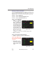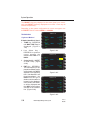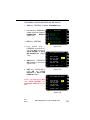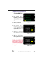
1
GNS-XL
FLIGHT MANAGEMENT SYSTEM
Operator’s Manual
Global
006-08852-0000
Rev. 4 Nov/04
N
WARNING
Prior to export of this document, review for export license requirement is
needed.
COPYRIGHT NOTICE
Copyright ©1998-2002, 2004 Honeywell International Inc.
All rights reserved.
Reproduction of this publication or any portion thereof by any means without
the express written permission of Honeywell International Inc. is prohibited.
For further information contact the Manager, Technical Publications;
Honeywell; One Technology Center; 23500 West 105th Street; Olathe,
Kansas 66061. Telephone: (913) 712-0400.
Revision History and Instructions
Manual
GNS-XL Operator’s Manual
Revision
4, November 2004
Part Number
006-08852-0000
This revision adds descriptions of operational procedures required to fly
three kinds of SIDs.
Insert the contents of this revision packet according to the following
instructions:
Title Page
Remove and Replace
Revision History Page
Insert Ahead of Existing Revision History Pages
Section 3
Remove and Replace Pages 3-17 through 3-22
Back Cover Page
Remove and Replace
Back Binder Insert
Remove and Replace
R-1
Rev. 4
Nov/04
GNS-XL Flight Management System
Revision History and Instructions
Manual
GNS-XL Operator’s Manual
Revision
3, October, 2002
Part Number
006-08852-0000
This revision incorporates AFIS Printer Control, deletes Air Canada and calrifies SID/STAR operation.
Insert the contents of this revision packet according to the following
instructions:
Front Binder Insert
Remove and Replace
Title Page
Remove and Replace
Revision History Page
Insert Ahead of Existing Revision History Page
Table of Contents
Remove and Replace Pages v/vi and xi through
xvi
Section 3
Remove and Replace Pages 3-9 through 3-12
Insert Page 3-12a/3-12b after Page 3-12
Remove and Replace Pages 3-13 through 3-20
and Page 3-75/3-76
Section 7
Remove and Replace Pages 7-1/7-2,7-7/7-8,
7-17 through 7-22, 7-35/7-36, 7-43 through
7-66 and insert Pages 7-67 through 7-72
Back Cover Page
Remove and Replace
Back Binder Insert
Remove and Replace
R-1
Rev. 3
Oct/02
GNS-XL Flight Management System
Revision History and Instructions
Manual
GNS-XL Operator’s Manual
Revision
2, April, 2000
Part Number
006-08852-0000
This revision incorporates GNS-XL Software Mod 6.
Insert the contents of this revision packet according to the following
instructions:
Front Binder Insert
Remove and Replace
Title Page
Remove and Replace
Revision History Page
Insert Ahead of Existing Revision History Page
Table of Contents
Remove and Replace Pages v/vi
Section 2
Remove and Replace Pages 2-1/2-2, 2-73
through 2-76 and 2-79/2-80
Section 3
Remove and Replace Pages 3-1 through 3-4,
3-15/3-16, 3-36.1/3-36.2 and 3-109/3-110
Back Cover Page
Remove and Replace
Back Binder Insert
Remove and Replace
R-1
Rev. 2
Apr/00
GNS-XL Flight Management System
Revision History and Instructions
Manual
GNS-XL Operator’s Manual
Revision
1, July 1998
Part Number
006-08852-0000
This revision consists of the following:
Add Company Routes (vi, 2-2, 3.36.1, 3-36.2, I-2)
Add Dedicated DME Interface (2-57)
Add Approach Note (3-36.3)
Add Waypoint Type Identifier (2-54, 3-48, 3-49, 3-62)
Revise Procedure Turn (3-41, 3-42, 3-43, 3-44)
Remove H Hot Key (3-57, 3-58, 3-61)
Add Fuel Use Reset Function (ix, 2-48, 3-105, 3-106)
Typographic/Administrative Corrections (Front Covers, 2-1, 2-4, 2-9, 2-10,
2-11, 2-12, 2-27, 2-28, 2-79, 3-1, 3-2, 3-3, 3-4, 3-40, 3-42, 3-43, 3-45,
3-59, 3-60, 7-12, 7-15, 7-20, 7-22, 7-54, 7-55, 7-56, 7-57, 7-58, 7-59, Back
Covers)
R-1
Rev. 1
Jul/98
GNS-XL Flight Management System
Revision History and Instructions
Manual
GNS-XL Operator’s Manual
Revision
0, October 1996
Part Number
006- 08852-0000
This revision is a complete manual revision and supersedes previous revision level manuals. Superseded manuals should be discarded.
R-1
Rev. 0
Feb/96
GNS-XL Flight Management System
Table of Contents
SECTION 1
DESCRIPTION . . . . . . . . . . . . . . . . . . . . . . . . . . . . . . . . . . . . . . . . . . . . . . . . . . .1-1
OVERVIEW . . . . . . . . . . . . . . . . . . . . . . . . . . . . . . . . . . . . . . . . . . . . . . . . . . .1-1
GENERAL TERMS . . . . . . . . . . . . . . . . . . . . . . . . . . . . . . . . . . . . . . . . . . . . . .1-3
CONTROLS AND INDICATORS . . . . . . . . . . . . . . . . . . . . . . . . . . . . . . . . . . . .1-4
ON: . . . . . . . . . . . . . . . . . . . . . . . . . . . . . . . . . . . . . . . . . . . . . . . . . . . . . . .1-4
BRIGHTNESS (BRT): . . . . . . . . . . . . . . . . . . . . . . . . . . . . . . . . . . . . . . . . .1-4
MESSAGE KEY/ANNUNCIATOR (MSG): . . . . . . . . . . . . . . . . . . . . . . . . . . .1-4
ALPHA KEYS: . . . . . . . . . . . . . . . . . . . . . . . . . . . . . . . . . . . . . . . . . . . . . . .1-5
NUMERIC KEYS: . . . . . . . . . . . . . . . . . . . . . . . . . . . . . . . . . . . . . . . . . . . .1-5
HOLD KEY: . . . . . . . . . . . . . . . . . . . . . . . . . . . . . . . . . . . . . . . . . . . . . . . . .1-5
BACK KEY: . . . . . . . . . . . . . . . . . . . . . . . . . . . . . . . . . . . . . . . . . . . . . . . . .1-6
SPACE (SP) KEY: . . . . . . . . . . . . . . . . . . . . . . . . . . . . . . . . . . . . . . . . . . . .1-6
ENTER (ENT) KEY: . . . . . . . . . . . . . . . . . . . . . . . . . . . . . . . . . . . . . . . . . . .1-6
DISPLAY SELECTOR KEYS: . . . . . . . . . . . . . . . . . . . . . . . . . . . . . . . . . . . .1-6
PREVIOUS (PRV) KEY: . . . . . . . . . . . . . . . . . . . . . . . . . . . . . . . . . . . . . . .1-7
NEXT (NXT) KEY: . . . . . . . . . . . . . . . . . . . . . . . . . . . . . . . . . . . . . . . . . . . .1-7
LINE SELECT KEYS: . . . . . . . . . . . . . . . . . . . . . . . . . . . . . . . . . . . . . . . . . .1-7
UP/DOWN KEYS: . . . . . . . . . . . . . . . . . . . . . . . . . . . . . . . . . . . . . . . . . . . .1-7
COLORS: . . . . . . . . . . . . . . . . . . . . . . . . . . . . . . . . . . . . . . . . . . . . . . . . . .1-8
SECTION 2
PAGE DISPLAY DEFINITIONS . . . . . . . . . . . . . . . . . . . . . . . . . . . . . . . . . . . . . . .2-1
PAGE DISPLAYS AT POWER-UP . . . . . . . . . . . . . . . . . . . . . . . . . . . . . . . . . .2-1
SELF TEST PAGE . . . . . . . . . . . . . . . . . . . . . . . . . . . . . . . . . . . . . . . . . . . .2-1
INITIALIZATION PAGE . . . . . . . . . . . . . . . . . . . . . . . . . . . . . . . . . . . . . . . .2-1
FLIGHT PLAN SECTION (FPL KEY) . . . . . . . . . . . . . . . . . . . . . . . . . . . . . . . . .2-2
FLIGHT PLAN PAGES . . . . . . . . . . . . . . . . . . . . . . . . . . . . . . . . . . . . . . . . .2-2
i
Rev. 0
Oct/96
GNS-XL Flight Management System
Table of Contents
FLIGHT PLAN LIST 1/1 (Page 1 of 1) . . . . . . . . . . . . . . . . . . . . . . . . . .2-2
FLIGHT PLAN “X” 1/1 (Page 1 of 1) . . . . . . . . . . . . . . . . . . . . . . . . . . .2-3
NAVIGATION SECTION (NAV KEY) . . . . . . . . . . . . . . . . . . . . . . . . . . . . . . . .2-13
NAVIGATION PAGES . . . . . . . . . . . . . . . . . . . . . . . . . . . . . . . . . . . . . . . .2-13
NAVIGATION 1/4 (Page 1 of 4) . . . . . . . . . . . . . . . . . . . . . . . . . . . . . .2-13
NAVIGATION 2/4 (Page 2 of 4) . . . . . . . . . . . . . . . . . . . . . . . . . . . . . .2-17
NAVIGATION 3/4 (Page 3 of 4) . . . . . . . . . . . . . . . . . . . . . . . . . . . . . .2-19
NAVIGATION 4/4 (Page 4 of 4) . . . . . . . . . . . . . . . . . . . . . . . . . . . . . .2-20
VLF SUBSECTION PAGES . . . . . . . . . . . . . . . . . . . . . . . . . . . . . . . . . . . .2-21
VLF SUBSECTION 1/4 (Page 1 of 4) . . . . . . . . . . . . . . . . . . . . . . . . . .2-21
VLF SUBSECTION 2/4 (Page 2 of 4) . . . . . . . . . . . . . . . . . . . . . . . . . .2-21
VLF SUBSECTION 3/4 (Page 3 of 4) . . . . . . . . . . . . . . . . . . . . . . . . . .2-23
VLF SUBSECTION 4/4 (Page 4 of 4) . . . . . . . . . . . . . . . . . . . . . . . . . .2-24
IRS/INS SUBSECTION PAGES . . . . . . . . . . . . . . . . . . . . . . . . . . . . . . . . .2-25
IRS (or INS) SUBSECTION 1/2 (Page 1 of 2) . . . . . . . . . . . . . . . . . . .2-25
IRS SUBSECTION 2/2 (Page 2 of 2) . . . . . . . . . . . . . . . . . . . . . . . . . .2-25
VPU SUBSECTION PAGES . . . . . . . . . . . . . . . . . . . . . . . . . . . . . . . . . . . .2-26
VPU SUBSECTION 1/4 (Page 1 of 4) . . . . . . . . . . . . . . . . . . . . . . . . . .2-26
VPU SUBSECTION 2/4 (Page 2 of 4) . . . . . . . . . . . . . . . . . . . . . . . . . .2-26
VPU SUBSECTION 3/4 (Page 3 of 4) . . . . . . . . . . . . . . . . . . . . . . . . . .2-27
VPU SUBSECTION 4/4 (Page 4 of 4) . . . . . . . . . . . . . . . . . . . . . . . . . .2-28
GPS SUBSECTION PAGES . . . . . . . . . . . . . . . . . . . . . . . . . . . . . . . . . . . .2-29
GPS SUBSECTION 1/3 (Page 1 of 3) . . . . . . . . . . . . . . . . . . . . . . . . . .2-29
GPS SUBSECTION 2/3 (Page 2 of 3) . . . . . . . . . . . . . . . . . . . . . . . . . .2-29
GPS SUBSECTION 3/3 (Page 3 of 3) . . . . . . . . . . . . . . . . . . . . . . . . . .2-31
VERTICAL NAVIGATION SECTION (VNAV KEY) . . . . . . . . . . . . . . . . . . . . . .2-32
VNAV 1/3 (Page 1 of 3) - (First line) . . . . . . . . . . . . . . . . . . . . . . . . . .2-32
ii
GNS-XL Flight Management System
Rev. 0
Oct/96
Table of Contents
VNAV MODE: (Second line) . . . . . . . . . . . . . . . . . . . . . . . . . . . . . . . .2-32
VNAV 2/3 (Page 2 of 3) - FLIGHT PLAN WayPoint . . . . . . . . . . . . . . .2-37
VNAV DATA 1/1 (Page 1 of 1) . . . . . . . . . . . . . . . . . . . . . . . . . . . . . . .2-38
VNAV WAYPOINT 1/1 (Page 1 of 1) . . . . . . . . . . . . . . . . . . . . . . . . . .2-40
AFIS SECTION (AFIS KEY) . . . . . . . . . . . . . . . . . . . . . . . . . . . . . . . . . . . . . .2-42
PLANNING SECTION (PLAN KEY) . . . . . . . . . . . . . . . . . . . . . . . . . . . . . . . .2-42
PLAN PAGES . . . . . . . . . . . . . . . . . . . . . . . . . . . . . . . . . . . . . . . . . . . . . .2-42
PLAN 1/8 (Page 1 of 8) FUEL STATUS . . . . . . . . . . . . . . . . . . . . . . . .2-42
PLAN 2/8 (Page 2 of 8) TRIP PLAN . . . . . . . . . . . . . . . . . . . . . . . . . . .2-44
PLAN 3/8 (Page 3 of 8) FUEL PLAN . . . . . . . . . . . . . . . . . . . . . . . . . .2-46
PLAN 4/8 (Page 4 of 8) FUEL FLOW . . . . . . . . . . . . . . . . . . . . . . . . . .2-47
PLAN 5/8 (Page 5 of 8) DATE/GMT . . . . . . . . . . . . . . . . . . . . . . . . . . .2-48
PLAN 6/8 (Page 6 of 8) AIRCRAFT WEIGHT . . . . . . . . . . . . . . . . . . . .2-48
PLAN 7/8 (Page 7 of 8) FDE PREDICTION . . . . . . . . . . . . . . . . . . . . . .2-49
FDE EXCLUDE SATS 1/1 (Page 1 of 1) . . . . . . . . . . . . . . . . . . . . . . . .2-50
PLAN 8/8 (Page 8 of 8) FDE COMPUTATION . . . . . . . . . . . . . . . . . . . .2-51
HEADING SECTION (HDG KEY) . . . . . . . . . . . . . . . . . . . . . . . . . . . . . . . . . .2-53
HEADING PAGE . . . . . . . . . . . . . . . . . . . . . . . . . . . . . . . . . . . . . . . . . . . .2-53
HEADING VECTOR 1/1 (Page 1 of 1) . . . . . . . . . . . . . . . . . . . . . . . . . .2-53
TUNING SECTION (TUNE KEY) . . . . . . . . . . . . . . . . . . . . . . . . . . . . . . . . . . .2-55
TUNE 1/4 (Page 1 of 4) COMM . . . . . . . . . . . . . . . . . . . . . . . . . . . . . .2-55
TUNE 2/4 (Page 2 of 4) COMM . . . . . . . . . . . . . . . . . . . . . . . . . . . . . .2-55
TUNE 3/4 (Page 3 of 4) NAV . . . . . . . . . . . . . . . . . . . . . . . . . . . . . . . .2-56
TUNE 4/4 (Page 4 of 4) XPDR/ADF . . . . . . . . . . . . . . . . . . . . . . . . . . .2-57
HOLDING PATTERN SECTION (HOLD KEY) . . . . . . . . . . . . . . . . . . . . . . . . .2-58
HOLDING PATTERN PAGE . . . . . . . . . . . . . . . . . . . . . . . . . . . . . . . . . . . .2-58
HOLDING PATTERN 1/1 (Page 1 of 1) . . . . . . . . . . . . . . . . . . . . . . . . .2-58
iii
Rev. 0
Oct/96
GNS-XL Flight Management System
Table of Contents
POSITION FIX PAGE . . . . . . . . . . . . . . . . . . . . . . . . . . . . . . . . . . . . . . . .2-63
DIRECT TO SECTION ( d KEY) . . . . . . . . . . . . . . . . . . . . . . . . . . . . . . . . . .2-64
DIRECT TO PAGES . . . . . . . . . . . . . . . . . . . . . . . . . . . . . . . . . . . . . . . . . .2-64
DIRECT 1/2 (Page 1 of 2) . . . . . . . . . . . . . . . . . . . . . . . . . . . . . . . . . .2-64
WAYPOINT SECTION . . . . . . . . . . . . . . . . . . . . . . . . . . . . . . . . . . . . . . . . . .2-65
WAYPOINT PAGES . . . . . . . . . . . . . . . . . . . . . . . . . . . . . . . . . . . . . . . . .2-65
DATABASE WPT 1/1 (Page 1 of 1) . . . . . . . . . . . . . . . . . . . . . . . . . . .2-65
SPECIAL DATABASE WAYPOINTS . . . . . . . . . . . . . . . . . . . . . . . . . . . . . .2-69
PILOT ENTERED WPT (Personalized) Waypoint . . . . . . . . . . . . . . . . .2-69
OFFSET WAYPOINT . . . . . . . . . . . . . . . . . . . . . . . . . . . . . . . . . . . . . . .2-70
SPECIAL WAYPOINTS . . . . . . . . . . . . . . . . . . . . . . . . . . . . . . . . . . . . .2-71
OCEANIC REPORTING WAYPOINTS . . . . . . . . . . . . . . . . . . . . . . . . . . . .2-72
MESSAGES (MSG Key) . . . . . . . . . . . . . . . . . . . . . . . . . . . . . . . . . . . . . . . .2-73
SYSTEM MESSAGES . . . . . . . . . . . . . . . . . . . . . . . . . . . . . . . . . . . . . . . .2-74
ACTION REQUIRED: . . . . . . . . . . . . . . . . . . . . . . . . . . . . . . . . . . . . . .2-74
ADVISORY: . . . . . . . . . . . . . . . . . . . . . . . . . . . . . . . . . . . . . . . . . . . . .2-75
SENSOR MESSAGES . . . . . . . . . . . . . . . . . . . . . . . . . . . . . . . . . . . . . . . .2-78
SECTION 3
SYSTEM OPERATION . . . . . . . . . . . . . . . . . . . . . . . . . . . . . . . . . . . . . . . . . . . . .3-1
PRE-DEPARTURE . . . . . . . . . . . . . . . . . . . . . . . . . . . . . . . . . . . . . . . . . . . . . .3-1
POWER ON/OFF AND PARALLAX ADJUSTMENT . . . . . . . . . . . . . . . . . . . .3-1
INITIALIZATION PAGE . . . . . . . . . . . . . . . . . . . . . . . . . . . . . . . . . . . . . . . .3-2
DATE and GMT . . . . . . . . . . . . . . . . . . . . . . . . . . . . . . . . . . . . . . . . . . . . .3-2
INITIALIZATION POSITION . . . . . . . . . . . . . . . . . . . . . . . . . . . . . . . . . . . .3-3
Option 1: Using the IDENT field for non-IRS equipped systems . . . . . .3-3
Option 2: Using the POS field . . . . . . . . . . . . . . . . . . . . . . . . . . . . . . . .3-5
BUILDING FLIGHT PLANS (FPL) . . . . . . . . . . . . . . . . . . . . . . . . . . . . . . . . . .3-7
iv
GNS-XL Flight Management System
Rev. 0
Oct/96
Table of Contents
CREATING A FLIGHT PLAN . . . . . . . . . . . . . . . . . . . . . . . . . . . . . . . . . . . .3-7
To Delete a Waypoint
. . . . . . . . . . . . . . . . . . . . . . . . . . . . . . . . . . . . . .3-8
MODIFYING A FLIGHT PLAN . . . . . . . . . . . . . . . . . . . . . . . . . . . . . . . . . . .3-8
To Access The Desired Flight Plan: . . . . . . . . . . . . . . . . . . . . . . . . . . . .3-8
Deleting A Waypoint: . . . . . . . . . . . . . . . . . . . . . . . . . . . . . . . . . . . . . . .3-9
ADDING A WAYPOINT . . . . . . . . . . . . . . . . . . . . . . . . . . . . . . . . . . . . . . . .3-9
ADDING OCEANIC WAYPOINTS . . . . . . . . . . . . . . . . . . . . . . . . . . . . . . .3-10
USING DUPLICATE WAYPOINT IDENTIFIERS . . . . . . . . . . . . . . . . . . . . .3-11
REVIEWING WAYPOINT DATA/COORDINATES . . . . . . . . . . . . . . . . . . . .3-12
To Access The Desired Flight Plan: . . . . . . . . . . . . . . . . . . . . . . . . . .3-12a
ERASING A STORED FLIGHT PLAN . . . . . . . . . . . . . . . . . . . . . . . . . . . . .3-12
FLIGHT PLAN (FPL) SELECTION . . . . . . . . . . . . . . . . . . . . . . . . . . . . . . . . .3-13
INITIAL LEG SELECTION . . . . . . . . . . . . . . . . . . . . . . . . . . . . . . . . . . . . .3-14
BEFORE TAXI (IRS EQUIPPED) . . . . . . . . . . . . . . . . . . . . . . . . . . . . . . . .3-15
RUNWAY LINE-UP (IRS EQUIPPED) . . . . . . . . . . . . . . . . . . . . . . . . . . . . . .3-15
IRS, VLF (RPU), GPS AND/OR VPU EQUIPPED . . . . . . . . . . . . . . . . . . . .3-15
VLF (RPU) AND/OR VPU EQUIPPED ONLY . . . . . . . . . . . . . . . . . . . . . . .3-15
SIDs, STARs, APPROACHES AND ENROUTE AIRWAYS . . . . . . . . . . . . .3-16
ENTERING A SID ON THE ACTIVE FPL . . . . . . . . . . . . . . . . . . . . . . . . . .3-18
REVIEWING A SID FROM ANY STORED FPL OR THE ACTIVE FPL PAGE 3-20
EDITING A SID FROM ANY STORED FPL OR THE ACTIVE FPL PAGE . . .3-21
ERASING A SID FROM ANY STORED FPL OR THE ACTIVE FPL PAGE . .3-22
ADDING OR DELETING WAYPOINTS WITHIN A SID . . . . . . . . . . . . . . . .3-23
To Delete a Waypoint . . . . . . . . . . . . . . . . . . . . . . . . . . . . . . . . . . . . . .3-23
ENTERING AN AIRWAY FROM ANY STORED FPL
OR THE ACTIVE FPL PAGE . . . . . . . . . . . . . . . . . . . . . . . . . . . . . . . . . . .3-24
Option 1 . . . . . . . . . . . . . . . . . . . . . . . . . . . . . . . . . . . . . . . . . . . . . . . .3-24
Option 2
. . . . . . . . . . . . . . . . . . . . . . . . . . . . . . . . . . . . . . . . . . . . . . .3-25
v
Rev. 3
Oct/02
GNS-XL Flight Management System
Table of Contents
EDITING AN AIRWAY . . . . . . . . . . . . . . . . . . . . . . . . . . . . . . . . . . . . . . . .3-26
ENTERING A STAR OR PROFILE DESCENT ON ANY STORED FPL
OR THE ACTIVE FPL PAGE . . . . . . . . . . . . . . . . . . . . . . . . . . . . . . . . . . .3-27
REVIEWING A STAR FROM A STORED FPL OR THE ACTIVE FPL PAGE .3-29
EDITING A STAR FROM A STORED FPL OR THE ACTIVE FPL PAGE . . . .3-29
ERASING A STAR FROM A STORED FPL OR THE ACTIVE FPL PAGE . . .3-30
ADDING WAYPOINTS WITHIN A STAR . . . . . . . . . . . . . . . . . . . . . . . . . .3-31
DELETING WAYPOINTS OF A STAR . . . . . . . . . . . . . . . . . . . . . . . . . . . .3-31
ENTERING AN APPROACH ON A STORED FPL
OR THE ACTIVE FPL PAGE . . . . . . . . . . . . . . . . . . . . . . . . . . . . . . . . . . .3-32
REVIEWING AN APPROACH FROM A STORED FPL
OR THE ACTIVE FPL PAGE . . . . . . . . . . . . . . . . . . . . . . . . . . . . . . . . . . .3-34
EDITING AN APPROACH FROM A STORED FPL
OR THE ACTIVE FPL PAGE . . . . . . . . . . . . . . . . . . . . . . . . . . . . . . . . . . .3-34
ERASING AN APPROACH FROM A STORED FPL
OR THE ACTIVE FPL . . . . . . . . . . . . . . . . . . . . . . . . . . . . . . . . . . . . . . . .3-35
DELETING AN APPROACH WAYPOINT . . . . . . . . . . . . . . . . . . . . . . . . . .3-36
USING A STAR AND AN APPROACH IN THE SAME FLIGHT PLAN . . . . .3-36
SELECTING A COMPANY ROUTE AND ADDING IT TO THE
ACTIVE FLIGHT PLAN . . . . . . . . . . . . . . . . . . . . . . . . . . . . . . . . . . . . . .3-36.1
EXECUTING APPROACHES . . . . . . . . . . . . . . . . . . . . . . . . . . . . . . . . . . . . .3-37
LOADING A GPS/GPS OVERLAY APPROACH . . . . . . . . . . . . . . . . . . . . .3-38
EXECUTING A GPS/GPS OVERLAY APPROACH . . . . . . . . . . . . . . . . . . .3-39
Using Radar Vectors to FINAL APPROACH COURSE . . . . . . . . . . . . . .3-39
After receiving the final intercept vector from ATC: . . . . . . . . . . . . . . .3-40
USING OWN NAVIGATION - NO DME ARC . . . . . . . . . . . . . . . . . . . . .3-41
PROCEDURE TURN . . . . . . . . . . . . . . . . . . . . . . . . . . . . . . . . . . . . . . . . .3-41
USING RADAR VECTORS TO INTERCEPT A DME ARC . . . . . . . . . . . . . .3-44
ENROUTE . . . . . . . . . . . . . . . . . . . . . . . . . . . . . . . . . . . . . . . . . . . . . . . . . . .3-51
DIRECT TO - ACTIVE FLIGHT PLAN WAYPOINT . . . . . . . . . . . . . . . . . . .3-51
DIRECT TO - HP WAYPOINT . . . . . . . . . . . . . . . . . . . . . . . . . . . . . . . . . .3-52
vi
GNS-XL Flight Management System
Rev. 1
Jul/98
Table of Contents
To Select and Go Direct To HP Waypoint: . . . . . . . . . . . . . . . . . . . . . .3-52
To Cancel Holding Pattern:(from the Holding Pattern page) . . . . . . . .3-52
DIRECT TO - RANDOM WAYPOINT . . . . . . . . . . . . . . . . . . . . . . . . . . . . .3-53
DIRECT TO - CLOSEST AIRPORT . . . . . . . . . . . . . . . . . . . . . . . . . . . . . .3-54
PSEUDO-VORTAC (SELECTED COURSE) . . . . . . . . . . . . . . . . . . . . . . . .3-55
USING HEADING VECTOR . . . . . . . . . . . . . . . . . . . . . . . . . . . . . . . . . . . . . .3-57
PROGRAMMING A HEADING VECTOR . . . . . . . . . . . . . . . . . . . . . . . . . .3-57
CHANGING HEADING VECTOR WHILE IN HEADING SELECT MODE . . . .3-58
CHANGING TO WAYPOINT WHILE IN HEADING SELECT MODE . . . . . . .3-58
CANCELING HEADING SELECT MODE . . . . . . . . . . . . . . . . . . . . . . . . . . .3-59
PROGRAMMING AN INTERCEPT . . . . . . . . . . . . . . . . . . . . . . . . . . . . . . .3-59
PROGRAMMING A HEADING INTERCEPT TO THE
FINAL APPROACH COURSE . . . . . . . . . . . . . . . . . . . . . . . . . . . . . . . . . .3-61
PROGRAMMING A HOLDING PATTERN . . . . . . . . . . . . . . . . . . . . . . . . . . . .3-63
REVIEWING, EDITING, OR CANCELING A HOLDING PATTERN . . . . . . . . . .3-65
REVIEWING . . . . . . . . . . . . . . . . . . . . . . . . . . . . . . . . . . . . . . . . . . . . . . .3-65
EDITING . . . . . . . . . . . . . . . . . . . . . . . . . . . . . . . . . . . . . . . . . . . . . . . . . .3-66
CANCELING . . . . . . . . . . . . . . . . . . . . . . . . . . . . . . . . . . . . . . . . . . . . . . .3-66
EXITING A HOLDING PATTERN . . . . . . . . . . . . . . . . . . . . . . . . . . . . . . . . . .3-66
EXITING HOLDING PATTERN NEXT TIME OVER HOLDING FIX . . . . . . . .3-67
EXITING HOLDING PATTERN BY GOING DIRECT TO HOLDING FIX . . . .3-68
EXITING HOLDING PATTERN BY PERFORMING A LEG CHANGE . . . . . .3-68
VERTICAL NAVIGATION (VNAV) OPERATION - PRE-DEPARTURE . . . . . . .3-71
SETTING CRUISE ALTITUDE, TRANSITION LEVEL,
AND DEFAULT FLIGHT PATH ANGLE . . . . . . . . . . . . . . . . . . . . . . . . . . . .3-71
CREATING/CHANGING VNAV WAYPOINTS . . . . . . . . . . . . . . . . . . . . . . .3-72
To program a Path Descent
. . . . . . . . . . . . . . . . . . . . . . . . . . . . . . . .3-74
REVIEWING VNAV WAYPOINTS . . . . . . . . . . . . . . . . . . . . . . . . . . . . . . .3-75
vii
Rev. 0
Oct/96
GNS-XL Flight Management System
Table of Contents
Using Active Flight Plan Page . . . . . . . . . . . . . . . . . . . . . . . . . . . . . . .3-75
Using VNAV Flight Plan Waypoints Page . . . . . . . . . . . . . . . . . . . . . . .3-76
VERTICAL NAVIGATION - ENROUTE . . . . . . . . . . . . . . . . . . . . . . . . . . . . . .3-76
PROGRAMMING VERTICAL PATH DESCENTS . . . . . . . . . . . . . . . . . . . .3-76
Using Database (DB) FPA . . . . . . . . . . . . . . . . . . . . . . . . . . . . . . . . . .3-77
Using Default ( DEF) FPA . . . . . . . . . . . . . . . . . . . . . . . . . . . . . . . . . . .3-77
Using Manual (MAN) FPA . . . . . . . . . . . . . . . . . . . . . . . . . . . . . . . . . .3-77
Using Automatic (AUTO) FPA . . . . . . . . . . . . . . . . . . . . . . . . . . . . . . .3-78
EDITING ALTITUDE CONSTRAINTS . . . . . . . . . . . . . . . . . . . . . . . . . . . . .3-79
Option 1: Using VNAV Page . . . . . . . . . . . . . . . . . . . . . . . . . . . . . . . . .3-79
Option 2: Using VNAV FPL WAYPOINT Page . . . . . . . . . . . . . . . . . . . .3-79
Option 3: Using the VNAV WAYPOINT Page . . . . . . . . . . . . . . . . . . . .3-80
DIRECT TO - VNAV WAYPOINT AS LATERAL WAYPOINT . . . . . . . . . . . .3-81
DIRECT TO - VNAV WAYPOINT . . . . . . . . . . . . . . . . . . . . . . . . . . . . . . . .3-83
CREATING VNAV PROFILE WAYPOINTS . . . . . . . . . . . . . . . . . . . . . . . . .3-84
Top of Climb (#TOC) . . . . . . . . . . . . . . . . . . . . . . . . . . . . . . . . . . . . . .3-84
Top of Descent (#TOD) . . . . . . . . . . . . . . . . . . . . . . . . . . . . . . . . . . . .3-85
Pre-Selected Altitude Intercept Point (#PRESL) . . . . . . . . . . . . . . . . .3-86
Descent Reference Waypoints . . . . . . . . . . . . . . . . . . . . . . . . . . . . . . .3-86
REMOTE TUNING . . . . . . . . . . . . . . . . . . . . . . . . . . . . . . . . . . . . . . . . . . . . . . .3-89
TUNING COMMS . . . . . . . . . . . . . . . . . . . . . . . . . . . . . . . . . . . . . . . . . . . . .3-89
TUNING NAVs . . . . . . . . . . . . . . . . . . . . . . . . . . . . . . . . . . . . . . . . . . . . .3-90
Keyboard Method . . . . . . . . . . . . . . . . . . . . . . . . . . . . . . . . . . . . . . . .3-90
TRANSPONDER AND ADF KEYBOARD TUNE . . . . . . . . . . . . . . . . . . . . .3-93
PLANNING PROCEDURES . . . . . . . . . . . . . . . . . . . . . . . . . . . . . . . . . . . . . .3-95
FUEL PLANNING . . . . . . . . . . . . . . . . . . . . . . . . . . . . . . . . . . . . . . . . . . .3-95
TRIP PLANNING . . . . . . . . . . . . . . . . . . . . . . . . . . . . . . . . . . . . . . . . . . .3-96
viii
GNS-XL Flight Management System
Rev. 0
Oct/96
Table of Contents
To Enter Manual Groundspeed: . . . . . . . . . . . . . . . . . . . . . . . . . . . . . .3-98
To Return to Automatic Groundspeed: . . . . . . . . . . . . . . . . . . . . . . . .3-98
To update the TRIP PLAN leg to the current TO waypoint
with an Active Flight Plan selected: . . . . . . . . . . . . . . . . . . . . . . . . . .3-100
FLIGHT PLAN FUEL PLANNING . . . . . . . . . . . . . . . . . . . . . . . . . . . . . . .3-100
To Enter Manual Groundspeed: . . . . . . . . . . . . . . . . . . . . . . . . . . . . .3-102
To Return To Automatic Groundspeed: . . . . . . . . . . . . . . . . . . . . . . .3-102
To Enter A Manual Fuel Flow: . . . . . . . . . . . . . . . . . . . . . . . . . . . . . .3-102
To Return to Automatic Fuel Flow: . . . . . . . . . . . . . . . . . . . . . . . . . .3-102
VERIFYING OR CHANGING DATE AND TIME . . . . . . . . . . . . . . . . . . . . .3-104
VERIFYING OR CHANGING AIRCRAFT WEIGHT PARAMETERS . . . . . .3-105
RESETTING FUEL USED . . . . . . . . . . . . . . . . . . . . . . . . . . . . . . . . . . . .3-106
SPECIAL PROCEDURES . . . . . . . . . . . . . . . . . . . . . . . . . . . . . . . . . . . . . . .3-107
PILOT ENTERED LEG CHANGE . . . . . . . . . . . . . . . . . . . . . . . . . . . . . . .3-107
PREVENTING AUTOMATIC LEG CHANGES . . . . . . . . . . . . . . . . . . . . . .3-109
DEAD RECKONING (DR) TO PRIMARY NAVIGATION MODE VLF (RPU) ONLY EQUIPPED . . . . . . . . . . . . . . . . . . . . . . . . . . . . . . . . .3-110
POSITION CHECK AND UPDATE PROCEDURES . . . . . . . . . . . . . . . . . .3-110
Using a Sensor . . . . . . . . . . . . . . . . . . . . . . . . . . . . . . . . . . . . . . . . .3-110
Over Known Point . . . . . . . . . . . . . . . . . . . . . . . . . . . . . . . . . . . . . . .3-111
Using An Offset . . . . . . . . . . . . . . . . . . . . . . . . . . . . . . . . . . . . . . . . .3-112
PARALLEL COURSE . . . . . . . . . . . . . . . . . . . . . . . . . . . . . . . . . . . . . . .3-114
MANUAL MAGNETIC VARIATION ENTRY . . . . . . . . . . . . . . . . . . . . . . .3-115
RETURNING TO AUTOMATIC VARIATION . . . . . . . . . . . . . . . . . . . . . . . . .3-115
SELECTING ETE, ETA, DIS, OR ALT DISPLAY OPTION . . . . . . . . . . . . .3-115
SELECTING NAV PAGE ETA OR ALT DISPLAY OPTION
. . . . . . . . . . . .3-116
INITIALIZATION ENROUTE VLF (RPU) ONLY . . . . . . . . . . . . . . . . . . . .3-117
Position Update: . . . . . . . . . . . . . . . . . . . . . . . . . . . . . . . . . . . . . . . .3-118
MANUAL TAS ENTRY only VLF is available . . . . . . . . . . . . . . . . . . . . . .3-118
ix
Rev. 1
Jul/98
GNS-XL Flight Management System
Table of Contents
MANUAL HEADING ENTRY only if IRS or VLF is available . . . . . . . . . . .3-119
VLF/OMEGA STATION DESELECTION . . . . . . . . . . . . . . . . . . . . . . . . . .3-120
SENSOR DESELECTION . . . . . . . . . . . . . . . . . . . . . . . . . . . . . . . . . . . . .3-121
EXTERNAL WAYPOINT ACCEPTANCE . . . . . . . . . . . . . . . . . . . . . . . . . .3-122
PRESENT POSITION AS A WAYPOINT . . . . . . . . . . . . . . . . . . . . . . . . .3-123
TRUE HEADING . . . . . . . . . . . . . . . . . . . . . . . . . . . . . . . . . . . . . . . . . . .3-124
Aircraft Equipped With TRUE/MAG Switch . . . . . . . . . . . . . . . . . . . .3-124
Aircraft Not Equipped With A TRUE/MAG Switch . . . . . . . . . . . . . . .3-125
SET HEADING ENTRY . . . . . . . . . . . . . . . . . . . . . . . . . . . . . . . . . . . . . .3-125
LOSS OF POWER IN FLIGHT . . . . . . . . . . . . . . . . . . . . . . . . . . . . . . . . .3-126
CREATING/CHANGING PILOT ENTERED
(PERSONALIZED) WAYPOINTS . . . . . . . . . . . . . . . . . . . . . . . . . . . . . . .3-127
Creating Pilot Entered (Personalized) Waypoints: . . . . . . . . . . . . . .3-128
Changing Pilot Entered (Personalized) Waypoints: . . . . . . . . . . . . . .3-128
CREATING AN OFFSET WAYPOINT . . . . . . . . . . . . . . . . . . . . . . . . . . . .3-129
PERFORMING FDE PREDICTION FOR OCEANIC/REMOTE OPERATION .3-130
SECTION 4
VLF/OMEGA TRANSMITTER SITES . . . . . . . . . . . . . . . . . . . . . . . . . . . . . . . . . .4-1
VLF COMMUNICATIONS STATIONS . . . . . . . . . . . . . . . . . . . . . . . . . . . . . . . .4-1
OMEGA NAVIGATIONAL NETWORK . . . . . . . . . . . . . . . . . . . . . . . . . . . . . . . .4-1
OMEGA NAVIGATIONAL NETWORK (Continued) . . . . . . . . . . . . . . . . . . . . . .4-2
SECTION 5
DATABASE UPDATE . . . . . . . . . . . . . . . . . . . . . . . . . . . . . . . . . . . . . . . . . . . . . .5-1
DATA BASE UPDATE PROCEDURES . . . . . . . . . . . . . . . . . . . . . . . . . . . . . . .5-1
TO UPDATE . . . . . . . . . . . . . . . . . . . . . . . . . . . . . . . . . . . . . . . . . . . . . . . .5-1
WHEN UPDATE IS COMPLETE . . . . . . . . . . . . . . . . . . . . . . . . . . . . . . . . . .5-2
IF UPDATE FAILS . . . . . . . . . . . . . . . . . . . . . . . . . . . . . . . . . . . . . . . . . . . .5-2
x
GNS-XL Flight Management System
Rev. 0
Oct/96
Table of Contents
SECTION 6
LIST OF ABBREVIATIONS AND DEFINITIONS . . . . . . . . . . . . . . . . . . . . . . . . . . .6-1
SECTION 7
DESCRIPTION . . . . . . . . . . . . . . . . . . . . . . . . . . . . . . . . . . . . . . . . . . . . . . . .7-1
Global Data Center (GDC) . . . . . . . . . . . . . . . . . . . . . . . . . . . . . . . . . . . . .7-2
Data Transfer Unit (DTU) . . . . . . . . . . . . . . . . . . . . . . . . . . . . . . . . . . . . . .7-2
Data Management Unit (DMU) . . . . . . . . . . . . . . . . . . . . . . . . . . . . . . . . . .7-2
Antenna Switching Unit (ASU) . . . . . . . . . . . . . . . . . . . . . . . . . . . . . . . . . .7-2
Satellite Communications Unit (SCU) . . . . . . . . . . . . . . . . . . . . . . . . . . . .7-3
High Power Amplifier/ Low Noise Amplifier (HPA/LNA) . . . . . . . . . . . . . . .7-3
Satellite Antenna . . . . . . . . . . . . . . . . . . . . . . . . . . . . . . . . . . . . . . . . . . . .7-3
PAGE DISPLAY DEFINITIONS . . . . . . . . . . . . . . . . . . . . . . . . . . . . . . . . . . . .7-3
AFIS Flight Plan List Page . . . . . . . . . . . . . . . . . . . . . . . . . . . . . . . . . . . . .7-3
Flight Plan Progress (NAVIGATION Page 5) . . . . . . . . . . . . . . . . . . . . . . .7-4
AFIS Menu Page . . . . . . . . . . . . . . . . . . . . . . . . . . . . . . . . . . . . . . . . . . . .7-6
AFIS FLT PLAN Pages . . . . . . . . . . . . . . . . . . . . . . . . . . . . . . . . . . . . . . . .7-7
AFIS FLT PLAN Page 1 . . . . . . . . . . . . . . . . . . . . . . . . . . . . . . . . . . . . . . . .7-7
Fuel and Time Requirements . . . . . . . . . . . . . . . . . . . . . . . . . . . . . . . . .7-7
AFIS FLT PLAN Page 2 . . . . . . . . . . . . . . . . . . . . . . . . . . . . . . . . . . . . . . . .7-9
Weights, Flight Level and Route . . . . . . . . . . . . . . . . . . . . . . . . . . . . . .7-9
AFIS FLT PLAN Page 3 . . . . . . . . . . . . . . . . . . . . . . . . . . . . . . . . . . . . . . .7-10
Operator Inputs . . . . . . . . . . . . . . . . . . . . . . . . . . . . . . . . . . . . . . . . . .7-10
AFIS FLT PLAN Page 4 . . . . . . . . . . . . . . . . . . . . . . . . . . . . . . . . . . . . . . .7-11
Performance Bias . . . . . . . . . . . . . . . . . . . . . . . . . . . . . . . . . . . . . . . .7-11
SIGMETS Pages . . . . . . . . . . . . . . . . . . . . . . . . . . . . . . . . . . . . . . . . . . . .7-11
TERMINAL WEATHER Pages . . . . . . . . . . . . . . . . . . . . . . . . . . . . . . . . . .7-12
TERMINAL WX DATA Pages . . . . . . . . . . . . . . . . . . . . . . . . . . . . . . . . . .7-13
xi
Rev. 0
Oct/96
GNS-XL Flight Management System
Table of Contents
WINDS ALOFT Pages . . . . . . . . . . . . . . . . . . . . . . . . . . . . . . . . . . . . . . . .7-13
WINDS ALOFT Data Pages . . . . . . . . . . . . . . . . . . . . . . . . . . . . . . . . . . . .7-13
RECALL AFIS FPL Page . . . . . . . . . . . . . . . . . . . . . . . . . . . . . . . . . . . . . .7-14
SEND AFIS MESSAGE Page . . . . . . . . . . . . . . . . . . . . . . . . . . . . . . . . . . .7-15
PPM MENU Page (Preprogrammed Messages) . . . . . . . . . . . . . . . . . . . .7-17
PREPROGRAMMED MESSAGE Pages . . . . . . . . . . . . . . . . . . . . . . . . . . .7-17
DISPLAY AFIS MSG Page . . . . . . . . . . . . . . . . . . . . . . . . . . . . . . . . . . . .7-18
OPERATING MODES Page (For AFIS Users Equipped with
Satellite Data Communications System) . . . . . . . . . . . . . . . . . . . . . . . . .7-18
AUTO REPORT: . . . . . . . . . . . . . . . . . . . . . . . . . . . . . . . . . . . . . . . . . .7-18
AUTO WX UPDT (weather update): . . . . . . . . . . . . . . . . . . . . . . . . . . .7-18
VHF LINK CONTROL Page . . . . . . . . . . . . . . . . . . . . . . . . . . . . . . . . . .7-20
SAT LINK CONTROL Page . . . . . . . . . . . . . . . . . . . . . . . . . . . . . . . . . .7-20
OPERATING MODES Page (For AFIS Users NOT Equipped with
Satellite Data Communications System) . . . . . . . . . . . . . . . . . . . . . . . . .7-21
AUTO REPORT: . . . . . . . . . . . . . . . . . . . . . . . . . . . . . . . . . . . . . . . . . .7-21
AUTO WX UPDT (weather update): . . . . . . . . . . . . . . . . . . . . . . . . . . .7-22
Active Flight Plan Page (for AFIS Flight Plan Updating) . . . . . . . . . . . . . .7-23
AFIS UPDATE Verification Page . . . . . . . . . . . . . . . . . . . . . . . . . . . . . . . .7-23
SYSTEM MESSAGES Page . . . . . . . . . . . . . . . . . . . . . . . . . . . . . . . . . . .7-24
SYSTEM MESSAGES . . . . . . . . . . . . . . . . . . . . . . . . . . . . . . . . . . . . . . . .7-24
ADVISORY: . . . . . . . . . . . . . . . . . . . . . . . . . . . . . . . . . . . . . . . . . . . . .7-24
SYSTEM OPERATION . . . . . . . . . . . . . . . . . . . . . . . . . . . . . . . . . . . . . . . . . .7-27
Pre-Departure . . . . . . . . . . . . . . . . . . . . . . . . . . . . . . . . . . . . . . . . . . . . . . . .7-27
AFIS Flight Plan Selection . . . . . . . . . . . . . . . . . . . . . . . . . . . . . . . . . . . .7-27
To enter an AFIS Flight Plan . . . . . . . . . . . . . . . . . . . . . . . . . . . . . . . . . . .7-27
ENROUTE . . . . . . . . . . . . . . . . . . . . . . . . . . . . . . . . . . . . . . . . . . . . . . . . .7-28
Reviewing Flight Plan Progress . . . . . . . . . . . . . . . . . . . . . . . . . . . . . . . .7-28
xii
GNS-XL Flight Management System
Rev. 3
Oct/02
Table of Contents
Reviewing AFIS Planned Leg Data . . . . . . . . . . . . . . . . . . . . . . . . . . . . . .7-28
Reviewing AFIS Flight Plan Data . . . . . . . . . . . . . . . . . . . . . . . . . . . . . . .7-29
AFIS Flight Plan Page 1 . . . . . . . . . . . . . . . . . . . . . . . . . . . . . . . . . . . . . .7-29
AFIS Flight Plan Page 2 . . . . . . . . . . . . . . . . . . . . . . . . . . . . . . . . . . . . . .7-30
AFIS Flight Plan Page 3 . . . . . . . . . . . . . . . . . . . . . . . . . . . . . . . . . . . . . .7-31
AFIS Flight Plan Page 4 . . . . . . . . . . . . . . . . . . . . . . . . . . . . . . . . . . . . . .7-31
SIGMETS Review/update . . . . . . . . . . . . . . . . . . . . . . . . . . . . . . . . . . . . .7-32
Terminal Weather Menu - Data update and Review . . . . . . . . . . . . . . . . .7-33
To insert a new identifier: . . . . . . . . . . . . . . . . . . . . . . . . . . . . . . . . . .7-34
To delete text when there is no data entry in progress: . . . . . . . . . . . .7-34
Winds Aloft Menu - Data update and Review . . . . . . . . . . . . . . . . . . . . . .7-34
To insert a new identifier: . . . . . . . . . . . . . . . . . . . . . . . . . . . . . . . . . .7-35
To delete text when there is no data entry in progress:
. . . . . . . . . . .7-36
Recalling AFIS Flight Plan . . . . . . . . . . . . . . . . . . . . . . . . . . . . . . . . . . . .7-36
Recall Option 1: . . . . . . . . . . . . . . . . . . . . . . . . . . . . . . . . . . . . . . . . . .7-36
Recall Option 2: . . . . . . . . . . . . . . . . . . . . . . . . . . . . . . . . . . . . . . . . . .7-37
Sending a Text Message or pdc . . . . . . . . . . . . . . . . . . . . . . . . . . . . . . .7-38
To Return to the AFIS Menu Page . . . . . . . . . . . . . . . . . . . . . . . . . . . . . .7-40
Sending/building a Preprogrammed Message . . . . . . . . . . . . . . . . . . . . .7-41
Editing/entering a Preprogrammed Message . . . . . . . . . . . . . . . . . . . . . .7-42
Continue Sending Message . . . . . . . . . . . . . . . . . . . . . . . . . . . . . . . . . . .7-42
AFIS Messages Review . . . . . . . . . . . . . . . . . . . . . . . . . . . . . . . . . . . . . .7-43
Selecting Operating Modes (For AFIS Users Equipped with
Satellite Data Communications System) . . . . . . . . . . . . . . . . . . . . . . . . .7-43
Auto Reporting . . . . . . . . . . . . . . . . . . . . . . . . . . . . . . . . . . . . . . . . . .7-43
Turning AUTO REPORT / auto wx update OFF . . . . . . . . . . . . . . . . . . .7-44
Returning to AUTO REPORT/auto wx update . . . . . . . . . . . . . . . . . . . .7-45
Auto Weather Update . . . . . . . . . . . . . . . . . . . . . . . . . . . . . . . . . . . . .7-46
xiii
Rev. 0
Oct/96
GNS-XL Flight Management System
Table of Contents
Turning AUTO WX UPDT OFF . . . . . . . . . . . . . . . . . . . . . . . . . . . . . . .7-46
Returning to AUTO WX UPDT . . . . . . . . . . . . . . . . . . . . . . . . . . . . . . .7-47
VHF and Satellite Network Operating Modes . . . . . . . . . . . . . . . . . . . . . .7-48
Turning VHF Network OFF . . . . . . . . . . . . . . . . . . . . . . . . . . . . . . . . . .7-48
Turning VHF Network ON . . . . . . . . . . . . . . . . . . . . . . . . . . . . . . . . . .7-49
Turning AUTO to MAN or OFF . . . . . . . . . . . . . . . . . . . . . . . . . . . . . . .7-50
Returning to AUTO . . . . . . . . . . . . . . . . . . . . . . . . . . . . . . . . . . . . . . .7-50
Turning Satellite Network OFF . . . . . . . . . . . . . . . . . . . . . . . . . . . . . . .7-51
Turning Satellite Network ON . . . . . . . . . . . . . . . . . . . . . . . . . . . . . . .7-52
Turning AUTO to MAN . . . . . . . . . . . . . . . . . . . . . . . . . . . . . . . . . . . . .7-53
Returning to AUTO . . . . . . . . . . . . . . . . . . . . . . . . . . . . . . . . . . . . . . .7-53
PRINTER CTRL . . . . . . . . . . . . . . . . . . . . . . . . . . . . . . . . . . . . . . . . . . . .7-54
Message DEST . . . . . . . . . . . . . . . . . . . . . . . . . . . . . . . . . . . . . . . . . . .7-54
Weather DEST . . . . . . . . . . . . . . . . . . . . . . . . . . . . . . . . . . . . . . . . . . .7-54
Auto Form Feed . . . . . . . . . . . . . . . . . . . . . . . . . . . . . . . . . . . . . . . . . .7-55
Auto Print MSG . . . . . . . . . . . . . . . . . . . . . . . . . . . . . . . . . . . . . . . . . .7-56
Auto Print WX . . . . . . . . . . . . . . . . . . . . . . . . . . . . . . . . . . . . . . . . . . . .7-56
PRINTING PROCEDURES . . . . . . . . . . . . . . . . . . . . . . . . . . . . . . . . . . . .7-57
Printing Flight Plans . . . . . . . . . . . . . . . . . . . . . . . . . . . . . . . . . . . . . . .7-57
Printing Messages . . . . . . . . . . . . . . . . . . . . . . . . . . . . . . . . . . . . . . . .7-57
Printing Weather . . . . . . . . . . . . . . . . . . . . . . . . . . . . . . . . . . . . . . . . .7-58
SELECTING OPERATING MODES (For AFIS Users NOT Equipped with
Satellite Data Communications System) . . . . . . . . . . . . . . . . . . . . . . . . .7-60
Auto Reporting . . . . . . . . . . . . . . . . . . . . . . . . . . . . . . . . . . . . . . . . . .7-60
Turning AUTO REPORT OFF . . . . . . . . . . . . . . . . . . . . . . . . . . . . . . . .7-60
Returning to AUTO REPORT . . . . . . . . . . . . . . . . . . . . . . . . . . . . . . . .7-61
Auto Weather Update . . . . . . . . . . . . . . . . . . . . . . . . . . . . . . . . . . . . .7-62
Turning AUTO WX UPDT OFF . . . . . . . . . . . . . . . . . . . . . . . . . . . . . . .7-62
xiv
GNS-XL Flight Management System
Rev. 3
Oct/02
Table of Contents
Returning to AUTO WX UPDT . . . . . . . . . . . . . . . . . . . . . . . . . . . . . . .7-63
Ground Network Operating Modes . . . . . . . . . . . . . . . . . . . . . . . . . . . . . .7-64
AUTO to MAN or OFF Mode . . . . . . . . . . . . . . . . . . . . . . . . . . . . . . . . .7-64
Returning to AUTO . . . . . . . . . . . . . . . . . . . . . . . . . . . . . . . . . . . . . . .7-65
Updating AFIS Flight Plan and Weather . . . . . . . . . . . . . . . . . . . . . . . . . .7-66
Updating AFIS Flight Plan . . . . . . . . . . . . . . . . . . . . . . . . . . . . . . . . . .7-66
Selecting Update as Active Flight Plan . . . . . . . . . . . . . . . . . . . . . . . . .7-67
Updating SIGMETS . . . . . . . . . . . . . . . . . . . . . . . . . . . . . . . . . . . . . . . . .7-68
Updating Weather . . . . . . . . . . . . . . . . . . . . . . . . . . . . . . . . . . . . . . . . . .7-69
To Update Terminal Weather Data Pages . . . . . . . . . . . . . . . . . . . . . .7-70
To insert a new identifier . . . . . . . . . . . . . . . . . . . . . . . . . . . . . . . . . . .7-70
Updating Winds Aloft . . . . . . . . . . . . . . . . . . . . . . . . . . . . . . . . . . . . . . . .7-70
To update the Winds Aloft Data Pages . . . . . . . . . . . . . . . . . . . . . . . .7-71
To insert a new identifier . . . . . . . . . . . . . . . . . . . . . . . . . . . . . . . . . . .7-71
xv
Rev. 3
Oct/02
GNS-XL Flight Management System
Table of Contents
THIS PAGE INTENTIONALLY LEFT BLANK
xvi
GNS-XL Flight Management System
Rev. 0
Oct/96
Description
SECTION 1
DESCRIPTION
OVERVIEW
The GNS-XL Flight Management System is an integrated system
designed to give the pilot centralized control for the navigation sensors, computer based flight planning, fuel management, and radio
management. The GNS-XL has a full color flat panel LCD display,
alpha-numeric and function keys, a Global Positioning Sensor (GPS),
and a navigation data base. All these are housed in a panel/pedestal
mounted Control Display Unit (CDU).
All aircraft interface requirements are accomplished through the
GNS-XL. The system supports analog and digital inputs in any combination. Specific aircraft requirements are programmed into a
Configuration Module. This module mounts directly to the rear connector, thus remaining in the aircraft. This allows hardware to be
easily moved between aircraft types without changing system configuration. The following is a summary of the digital and analog interfaces:
DIGITAL
ANALOG
AFIS
Air Data Computer
EFIS
Fuel Flow
Inertial Navigation Sensor
Inertial Reference Sensor
VOR/DME, ADF, XPDR, COMM
Radio Tuning
RPU - VLF/Omega
Cross Side FMS
Altitude
Altitude Rate
Cross Track Deviation
Discretes
Dual VOR/DME
Fuel Flow
Heading
HSI Course & Bearing
Roll Steering
True Air Speed
Vertical Deviation
In addition to the GPS sensor, position information is accepted from
up to eight navigation sensors, such as an optional VLF/Omega
RPU, inertial position sensors, or VOR/DME radios. These navigation
sensor inputs can be blended to form a single composite position.
Accuracy of this composite position is enhanced by using the best
Rev. 0
Oct/96
GNS-XL Flight Management System
1-1
Description
characteristics of each type of sensor. For example, an Inertial
Reference System (IRS) has excellent short term characteristics
while VLF/Omega has excellent long term stability. The internal GPS
sensor has excellent overall characteristics and will usually be the
dominant sensor during blending. However, when RAIM is available,
the GPS sensor is the sole contributor to the composite position.
NOTE: RAIM (Receiver Autonomous Integrity Monitoring) is a quality factor used to determine the accuracy of the GPS position. It is an
internal function of the GPS receiver and determines the accuracy of
it’s navigation solution.
The navigation data base is updated on a 28-day cycle by way of a
memory card. This card is inserted in a Personal Computer Memory
Card International Association (PCMCIA) slot located under the lower
portion of the alpha keyboard. This worldwide database contains
over 50,000 waypoints, navaids and airports. It also contains altitudes at appropriate waypoints, SID, STAR, AIRWAY, and
APPROACH procedures. In addition to this database, the memory
can store up to 999 operator generated waypoints. Individual navigation points can be organized into 56 different stored flight plans, each
containing up to 50 waypoints.
Due to the way the GNS-XL database is structured, waypoints must
have unique identifiers. However, some duplicate ICAO identifiers
exist for more than one waypoint. In these cases the waypoint identifiers are renamed in the database. Two naming conventions are
used, one for four character identifiers and one for five character
identifiers.
Four character waypoints keep the first four characters and the last
two characters of the ICAO airport identifier as shown in the following
example.
MA11 at KPRC becomes MA11RC in the database.
Five character waypoints keep the first five characters and add the
last character of the ICAO airport identifier as shown in the following
example.
MA27L at KOAK becomes MA27LK in the database.
Additional capabilities of the GNS-XL include direct navigation from
present position to any waypoint, and data crossfill capability for dual
installations. Trip Plan and Fuel Plan functions are also available.
There is capability for creating a PSEUDO-VORTAC (selected
1-2
GNS-XL Flight Management System
Rev. 0
Oct/96
Description
course) to any waypoint and establishing an offset parallel course.
NAVs, COMMs, ADFs and transponders can be tuned through the
system or by using the individual control heads.
GENERAL TERMS
FIELD:
A line of information.
CURSOR: Yellow rectangular box placed over a field to enter or
change the information in that field. The cursor is normally out of view unless brought into view by depressing
the Line Select Keys on either side of the screen. When
information is entered into a field and the ENT Key is
depressed, the cursor will move to the next enterable
field or disappear from the screen when the last field is
entered. Blinking of a field indicates that the computer
has not accepted the entry because of unreasonable or
invalid information.
PAGE:
Information is arranged in sections and subsections
much like chapters in a book. Individual screen displays
are referred to as pages. Each section is selected by
depressing the appropriate Display Selector Key located
at the top of the keyboard. Each subsequent push of the
key will select the next page of that section. A subsection page is selected by depressing the Line Select Key
next to the topic desired, then depressing the ENT Key.
The PRV or NXT Key can be used to move forward or
backward through pages of a subsection. If the first
page of a subsection is displayed, the BACK Key will
exit the subsection.
WAYPOINT:A navigation point consisting of 1 to 6 alpha, numeric
characters that has a specific latitude and longitude.
Rev. 0
Oct/96
GNS-XL Flight Management System
1-3
Description
CONTROLS AND INDICATORS
ON:
ON
D
BRT
AFIS
HOLD
MSG
Depress and release the ON
Key to apply power to the system. There is a warm-up period
of approximately 30 seconds.
The display illumination will initially be set at 75% of full bright.
NAV
VNAV
HDG
TUNE
A
B
C
D
E
F
Depressing the ON Key for
1 2 3
G H
I
J
K
L
M N O P Q R
4 5 6
approximately three seconds
S
7 8 9
T U V W X
will initiate the system power off
Y Z SP #
± 0
*
sequence. During the sequence
the display will show SYSTEM TURNING OFF. This is to prevent
inadvertent system shutdown.
FPL
PRV
PLAN
NXT
BACK
ENT
NOTE: The system is also capable of being turned on and off by
cycling aircraft power.
ON
BRIGHTNESS (BRT):
D
BRT
AFIS
HOLD
MSG
The BRT Key is used to change
the illumination of the display.
This key is also used for parallax adjustment of the Line
Select Keys
NOTE: The illumination of the
front panel and keyboard is normally controlled through the aircraft panel lighting control.
NAV
VNAV
FPL
PLAN
PRV
NXT
BACK
TUNE
A
B
C
D
E
1
2
3
G
H
I
J
K
L
4
5
6
M
N
O
P
Q
R
7
8
9
S
T
U
V
W
X
±
0
*
Y
Z
SP
#
ENT
HDG
ON
MESSAGE KEY/ANNUNCIATOR (MSG):
The MSG annunciator will flash
to alert the operator that a message needs to be viewed on
one of the SYSTEM MESSAGES or SENSOR MESSAGES Pages.
D
VNAV
FPL
PLAN
PRV
NXT
BACK
1-4
BRT
AFIS
NAV
F
HOLD
MSG
TUNE
A
B
C
D
E
1
2
3
G
H
I
J
K
L
4
5
6
M
N
O
P
Q
R
7
8
9
S
T
U
V
W
X
±
0
*
Y
Z
SP
#
ENT
HDG
GNS-XL Flight Management System
F
Rev. 0
Oct/96
Description
Depressing the MSG Key will display the message page. The
newest message will be indicated with a flashing asterisk to the left of
the message. If the message requires some action be taken by the
operator, the MSG annunciator will remain on steadily until the action
is completed. If no action is required, the MSG annunciator will extinguish when the message page is exited.
ON
D
BRT
AFIS
HOLD
MSG
ALPHA KEYS:
The alpha keys are used to
enter the 26 letters of the alphabet, and #.
NAV
VNAV
FPL
PLAN
PRV
NXT
BACK
TUNE
A
B
C
D
E
1
2
3
G
H
I
J
K
L
4
5
6
M
N
O
P
Q
R
7
8
9
S
T
U
V
W
X
±
0
*
Y
Z
SP
#
ENT
HDG
ON
NUMERIC KEYS:
D
F
BRT
AFIS
HOLD
MSG
The numeric keys are used to
enter numbers 0 to 9, ± and *.
HOLD KEY:
If the cursor is positioned over a
waypoint identifier, and it is
appropriate to program a
Holding Pattern at that waypoint, depressing the HOLD
Key accesses the Holding
Pattern page.
If the cursor is not displayed,
depressing the HOLD Key
accesses the POSITION FIX
Page and is used for position
updates and verification as well
as entering the primary navigation mode.
Rev. 0
Oct/96
NAV
VNAV
FPL
PLAN
PRV
NXT
BACK
TUNE
A
B
C
D
E
1
2
3
G
H
I
J
K
L
4
5
6
M
N
O
P
Q
R
7
8
9
S
T
U
V
W
X
±
0
*
Y
Z
SP
#
ENT
HDG
ON
D
VNAV
FPL
PLAN
PRV
BRT
AFIS
NAV
NXT
BACK
F
HOLD
MSG
TUNE
A
B
C
D
E
1
2
3
G
H
I
J
K
L
4
5
6
M
N
O
P
Q
R
7
8
9
S
T
U
V
W
X
±
0
*
Y
Z
SP
#
ENT
HDG
GNS-XL Flight Management System
F
1-5
Description
ON
BACK (BACK) KEY:
The BACK Key is used to erase
errors and page backward
when the cursor is not displayed. It can also be used to
change data in a field if the cursor is present.
D
NAV
VNAV
FPL
PLAN
PRV
NXT
BACK
SPACE (SP) KEY:
BRT
AFIS
HOLD
TUNE
A
B
C
D
E
1
2
3
G
H
I
J
K
L
4
5
6
M
N
O
P
Q
R
7
8
9
S
T
U
V
W
X
±
0
*
Y
Z
SP
#
ENT
HDG
ON
D
MSG
F
BRT
AFIS
HOLD
MSG
The SP Key is used to enter a
space when entering a message on an AFIS Page. This
key is not functional if AFIS is
not installed in the system.
NAV
VNAV
FPL
PLAN
PRV
NXT
ENTER (ENT) KEY:
When the ENT Key is
depressed, data is entered into
the computer memory.
BACK
TUNE
A
B
C
D
E
1
2
3
G
H
I
J
K
L
4
5
6
M
N
O
P
Q
R
7
8
9
S
T
U
V
W
X
±
0
*
Y
Z
SP
#
ENT
HDG
ON
D
F
BRT
AFIS
HOLD
MSG
DISPLAY SELECTOR KEYS:
NAV (Navigation), VNAV
(Vertical Navigation), AFIS
(Airborne Flight Information
System), FPL (Flight Plan),
PLAN
(Planning),
HDG
(Heading), TUNE (Radio
Tuning), and d (Direct) are
used to select the pages pertaining to that particular section.
The first page of a section is displayed first when a Display
Selector Key is pressed. With
each subsequent press of the
Key, the next sequential page
will be displayed.
NAV
VNAV
FPL
PLAN
PRV
NXT
BACK
A
B
C
D
E
2
3
G
H
I
J
K
L
4
5
6
M
N
O
P
Q
R
7
8
9
S
T
U
V
W
X
±
0
*
Y
Z
SP
#
ENT
ON
D
NAV
VNAV
FPL
PLAN
PRV
NXT
F
BRT
AFIS
BACK
1-6
TUNE
1
HDG
HOLD
MSG
TUNE
A
B
C
D
E
1
2
3
G
H
I
J
K
L
4
5
6
M
N
O
P
Q
R
7
8
9
S
T
U
V
W
X
±
0
*
Y
Z
SP
#
ENT
HDG
GNS-XL Flight Management System
F
Rev. 0
Oct/96
Description
ON
PREVIOUS (PRV) KEY:
The PRV Key is used to display
the previous page of a section
or subsection. This key also
allows the operator to remain in
a section or subsection by looping from the first to the last and
back to the first page of that
section or subsection.
D
NAV
VNAV
FPL
PLAN
PRV
BRT
AFIS
NXT
BACK
HOLD
TUNE
A
B
C
D
E
1
2
3
G
H
I
J
K
L
4
5
6
M
N
O
P
Q
R
7
8
9
S
T
U
V
W
X
±
0
*
Y
Z
SP
#
ENT
HDG
ON
D
MSG
F
BRT
AFIS
HOLD
MSG
NEXT (NXT) KEY:
The NXT Key is used to display
the next page of a section or
subsection. This key also
allows the operator to remain in
a section or subsection by looping from the first to the last and
back to the first page of that
section or subsection.
NAV
VNAV
FPL
PLAN
PRV
NXT
BACK
TUNE
A
B
C
D
E
1
2
3
G
H
I
J
K
L
4
5
6
M
N
O
P
Q
R
7
8
9
S
T
U
V
W
X
±
0
*
Y
Z
SP
#
ENT
HDG
ON
D
F
BRT
AFIS
HOLD
MSG
LINE SELECT KEYS:
These keys are used to place
the cursor in the field next to
that key. Each line select key
controls 2 lines of text. White
symbols (< or >) displayed on
either side of the display indicate active Line Select Keys for
each individual page.
Rev. 0
Oct/96
NAV
VNAV
FPL
PLAN
PRV
NXT
BACK
TUNE
A
B
C
D
E
1
2
3
G
H
I
J
K
L
4
5
6
M
N
O
P
Q
R
7
8
9
S
T
U
V
W
X
±
0
*
Y
Z
SP
#
ENT
HDG
GNS-XL Flight Management System
F
1-7
Description
COLORS:
The CDU displays are color coded to assist the operator in recognizing information. The following is a list of these colors and their meanings:
1-8
Magenta
Lateral TO Waypoint and Vertical TO Waypoint,
Yellow
FROM Waypoint
Caution Messages
Data entered, but not yet accepted by the computer.
Cyan
Date and Times
Tuned Frequencies or Codes
Altitudes
Green
Navigation and Fuel Data
General Page Data
White
Page Titles and Prompts
Red
Warnings
Blue
Waypoint Numbers
GNS-XL Flight Management System
Rev. 0
Oct/96
Page Display Definitions
SECTION 2
PAGE DISPLAY DEFINITIONS
The following section contains definitions pertaining to information
and format seen when a particular function key is depressed.
PAGE DISPLAYS AT POWER-UP
For a better understanding of the GNS-XL functions, this section
should be reviewed prior to operating the system.
SELF TEST PAGE
SELF TEST
For the first 30 seconds after
the system if is turned on, the
computer performs extensive
internal tests that must be
successfully completed
before proceeding further. If
the system detects a problem
the SELF TEST display may
be replaced by a NO DATA
RECEIVED message. The
unit may have to be removed
for service.
INITIALIZATION PAGE
After the Self Test is successfully completed, the INITIALIZATION Page will be displayed. Refer to Figure 2-2.
GLOBAL
HONEYWELL
INTERNATIONAL INC.
COPYRIGHT 2000
ALL RIGHTS RESERVED
Figure 2-1
INITIALIZATION
DATE
01 JUN 00
GMT
18:42
IDENT KDAL
POS -------------------
>
DATE:
The current Greenwich Date
is displayed as day, month
and year.
18355-0101
>
SM06
>
Figure 2-2
GMT:
Time of day is displayed in Greenwich Mean Time hours and minutes.
Rev. 2
Apr/00
GNS-XL Flight Management System
2-1
Page Display Definitions
IDENT:
Displays the airport identifier for the airport closest to the system shut
down position. Dashes will be displayed when the cursor is placed
over the position (POS) field.
POS:
Displays the last system position at shut down. Dashes are displayed when the cursor is over the IDENT field.
PART NUMBER AND SOFTWARE MODIFICATION STATUS:
The bottom line of the display shows the unit part number and the
software level of the unit.
NOTE: This page cannot be recalled once DATE, GMT, and POS
have been entered. In order to display this again, the system must
be turned off and then turned back on.
FLIGHT PLAN SECTION (FPL KEY)
Upon pressing the FPL Key the FLIGHT PLAN LIST 1/1 Page will be
displayed and the following can be observed.
NOTE: The FLIGHT PLAN LIST page will be automatically displayed
if the ENT key is depressed at least three times while on the initialization page.
FLIGHT PLAN PAGES
NOTE: If AFIS equipped the first page displayed after system initialization will be the AFIS FPL LIST page in lieu of the FLIGHT PLAN
LIST page.
NOTE: If the data base contains company routes, the first page displayed after system initialization will be the COMPANY ROUTES
page in lieu of the FLIGHT PLAN LIST page. If both AFIS and
Company Routes are present, the COMPANY ROUTES page is displayed first.
FLIGHT PLAN LIST 1/1 (Page 1 of 1)
The FLIGHT PLAN LIST page will be displayed automatically after
system initialization. If the initialization airport matches a departure
airport on the FLIGHT PLAN LIST, the cursor will automatically be
positioned over the first matching Flight Plan.
2-2
GNS-XL Flight Management System
Rev. 1
Jul/98
Page Display Definitions
There are seven pages possible with a maximum of 56
flight plans stored in nonvolatile memory. Each
stored flight plan's origin and
destination points are listed
in alphabetical order. (Figure
2-3)
FLIGHT PLAN LIST 1/1
KABQ
KDAL
KDAL
KHPN
KHPN
KLAX
KPRC
KSFO
KMSY
KHPN
KSFO
KORD
KORD
KSTL
KSNA
KHPN
1
6
8
2
9
4
3
7
>
>
>
>
A new FLIGHT PLAN LIST
Figure 2-3
Page is created when the
previous page has eight flight
plan origin-destination pairs on it. Using the PRV or NXT Key pages
through the Flight Plan List subsection. (Figure 2-3)
FLIGHT PLAN "X" 1/1 (Page 1 of 1)
"X" can be Flight Plan numbers 1 through 56. (Figure
2-4)
This stored flight plan page is
accessed through the
FLIGHT PLAN LIST Page
by pressing the Line Select
Key corresponding to the
desired flight plan number,
thus, placing the cursor over
that number, then pressing
ENT. (Figure 2-3)
<
<
<
FLIGHT PLAN 6 1/1
KDAL
BUJ
HOT
BWZ
ISLET
<
DEPART
ARRIVE
<
APPROACH
XFILL
SELECT
ERASE
<
Figure 2-4
Waypoint Identifiers:
Waypoint identifiers may consist of from one to six alphanumeric
characters. Up to 50 waypoint identifiers may be placed on each
stored Flight Plan. An identifier may be used more than once on the
same Flight Plan. (Figure 2-4) Other indications can be as follows:
• Indented Waypoints: Indicates a SID, STAR, or APPROACH procedure is part of the Flight Plan. (Figure 2-4)
Rev. 0
Oct/96
GNS-XL Flight Management System
2-3
Page Display Definitions
• HP (Holding Pattern):
Indicates a holding pattern is
programmed at a particular
waypoint. (Figure 2-5)
• PT (Procedure Turn):
Indicates a procedure turn is
programmed at a particular
waypoint.
FLIGHT PLAN 6 2/2
RW34
+++++
<
HP CMK
#####
<
<
<
DEPART
ARRIVE
<
APPROACH
XFILL
SELECT
ERASE
<
• ++++++: A flight plan discontinuity "fence" separating
Figure 2-5
the missed approach waypoint from the rest of the approach (Figure 2-5). The system will fly
current track beyond the last waypoint prior to the fence but no Auto
Leg change will occur. No Altitude constraints will be displayed
beyond the fence. This type of fence will not cause waypoints of the
active flight plan to be deleted prior to the fence if a waypoint beyond
the fence is selected using the d function.
• IAF (Initial Approach Fix): Automatically loaded from the data base
when a non-precision approach is selected.
• ARC (DME Arc end waypoint): Automatically loaded from the data
base when a non-precision approach is selected.
• FAF (Final Approach Fix): Automatically loaded from the data base
when a non-precision approach is selected.
• MAP (Missed Approach Point): Automatically loaded from the data
base when a non-precision approach is selected.
• ------: "fence" indicating a discontinuity in the flight plan. No Auto
Leg changes will take place beyond the last waypoint prior to the
fence and no ALT, ETE, ETA, or DIS will be displayed. If a d is
performed to a waypoint beyond this type of fence all waypoints prior
to the fence will be deleted from the active flight plan.
• ****** : Follows the last waypoint on the Flight Plan and indicates
where the next waypoint entry will normally begin.
DEPART:
Used to access the DEPARTURE Page to enter a Standard
Instrument Departure (SID). (Figure 2-5)
ARRIVE:
Used to access the ARRIVAL Page to enter a Standard Terminal
Arrival (STAR) or Profile Descent. (Figure 2-5)
2-4
GNS-XL Flight Management System
Rev. 1
Jul/98
Page Display Definitions
APPROACH:
Used to access the APPROACH Page to enter a non-precision
approach. (Figure 2-5)
XFILL: Used to transfer information between systems in a dual system installation. In a single system installation, this prompt will not be
displayed.
SELECT or INVERT:
Used to transfer a Stored Flight Plan to the ACTIVE FLIGHT PLAN
Page. Depressing the BACK Key when the cursor is over this field
brings up INVERT?, which is used to transfer the waypoint of a
Stored Flight Plan to the ACTIVE FLIGHT PLAN Page in reverse
order. (Figure 2-5)
ERASE:
Used to clear an entire flight plan. (Figure 2-5)
DEPARTURE Page
Accessed by pressing the Line Select Key adjacent to DEPART on
the FLIGHT PLAN Page. With the cursor over DEPART press ENT.
NOTE: Each field will prefill if there is only one choice for that particular field or DEPARTURE airport field will flash if no Departure is
available. A NO SIDS AVAILABLE message will appear at the bottom of the screen.
DEPARTURE:
Departure airport identifier. This field prefills if first waypoint on the
flight plan is an airport or runway, or it can be manually entered.
(Figure 2-6)
RUNWAY:
Departing runway. This field
prefills if first waypoint on the
flight plan is a runway, or it
can be selected from a list
made available by pressing
the Line Select Key adjacent
to the RUNWAY field.
(Figure 2-6)
<
<
DEPARTURE
KLAX 1/1
RUNWAY
-----SID
-----TRANSITION
-----RW06L
RW06R
RW07L
RW07R
‘
<
<
erase
Figure 2-6
Rev. 0
Oct/96
GNS-XL Flight Management System
2-5
Page Display Definitions
SID:
The Standard Instrument Departure (SID) can be selected from a list
made available by pressing the Line Select Key adjacent to the SID
field.
TRANSITION:
The Transition waypoint can be selected from a list made available by
pressing the Line Select Key adjacent to the TRANSITION field.
WAYPOINTS OF SID:
DEPARTURE
KLAX 1/1
RUNWAY
RW06L
SID
GMN1
TRANSITION
AVE
WAYPOINTS OF SID:
GMN
COREZ
AVE
The waypoints that constitute
the SID. (Figure 2-7)
SELECT?:
Used to select the defined
SID. (Figure 2-7)
<
ERASE:
SELECT?
Used to erase a SID. (Figure
2-7)
‘
eraseERASE
<
<
<
Figure 2-7
ARRIVAL Page
Accessed by pressing the Line Select Key adjacent to ARRIVE on the
FLIGHT PLAN Page. With the cursor over ARRIVE press ENT.
NOTE: Each field will prefill if there is only one choice for that particular field or ARRIVAL field will flash if no Arrival is available, and a NO
STARS AVAILABLE message will appear at the bottom of the screen.
ARRIVAL:
Arrival airport identifier. This field prefills if the last waypoint on the
flight plan is an airport or runway, or can be manually
ARRIVAL KLAX
1/1 <
entered. (Figure 2-8)
RUNWAY
-----RUNWAY:
Arriving runway. This field
prefills if the last waypoint on
the flight plan is a runway, or
can be selected from a list
made available by pressing
the Line Select Key adjacent
to the RUNWAY field.
(Figure 2-8)
2-6
<
<
TRANSITION
STAR
RWO6L
RW06R
RW07L
RW07R
-----------
<
Figure 2-8
GNS-XL Flight Management System
Rev. 0
Oct/96
Page Display Definitions
TRANSITION:
The Transition waypoint may be prefilled or selected from a list made
available by pressing the Line Select Key adjacent to the TRANSITION field.
STAR:
The Standard Terminal Arrival (STAR) can be selected from a list
made available by pressing the Line Select Key adjacent to the
STAR field.
WAYPOINTS OF STAR:
ARRIVAL KLAX
1/1
RUNWAY
RW06L
TRANSITION
CIVET
STAR
CIVET1
WAYPOINTS OF STAR:
CIVET
BREMR
ARNES
The waypoints that constitute
the STAR. (Figure 2-9)
SELECT?:
Used to select the defined
STAR. (Figure 2-9)
<
ERASE:
SELECT?
Used to erase a STAR.
(Figure 2-9 )
ERASE
<
<
<
Figure 2-9
APPROACH Page
Accessed by pressing the Line Select Key adjacent to APPROACH
on the FLIGHT PLAN Page. With the cursor over APPROACH
press ENT.
NOTE: Each field will prefill if there is only one choice for that particular field or Approach Airport field will flash if no Approach is available and a NO APPROACH AVAILABLE message will appear at
the bottom of the screen.
APCH:
<
Approach airport identifier.
This field prefills if last waypoint on the flight plan is an
airport or runway, or can be
manually entered. (Figure 210)
<
<
<
APCH KLAX
RUNWAY
TYPE
TRANSITION
RW24R
RW24L
RW07R
RW07L
‘
1/2
----------------
eraseERASE
<
<
<
Figure 2-10
Rev. 0
Oct/96
GNS-XL Flight Management System
2-7
Page Display Definitions
RUNWAY:
Approach runway prefills if
only one runway is available,
last waypoint on Flight Plan
is a runway, or can be selected from a list made available
by pressing the Line Select
Key adjacent to the RUNWAY field. (Figure 2-11)
APCH KLAX
1/1
<
RUNWAY
RW24R
TYPE
NDB
<
TRANSITION
LAHAB
WPTS OF APPROACH:
IAF LAHAB MAP RW24R
LAX16
+++++
DOWNE
HP RAFFS
FAF OSNB
<
<
SELECT?erase
ERASE
<
TYPE (Circle, VOR, NDB, or
RNAV):
Figure 2-11
Type may be prefilled or selected from a list made available by pressing the Line Select Key adjacent to the TYPE field.
NOTE: If the runway selected on the Approach Page differs from the
runway dictated by the STAR, "SEL RWY FROM STAR PG" is displayed at the bottom of the screen.
TRANSITION:
The Transition waypoint may be prefilled or selected from a list made
available by pressing the Line Select Key adjacent to the TRANSITION field. (Figure 2-10)
WAYPOINTS OF APPROACH:
The waypoints that constitute the APPROACH. (Figure 2-11)
• HP (Holding Pattern):
Indicates a holding pattern is programmed at a particular waypoint.
(Figure 2-11)
• PT (Procedure Turn):
Indicates a Procedure Turn is programmed at a particular waypoint.
• ARC (DME ARC):
Indicates a DME ARC is programmed at a particular waypoint.
• IAF:
Indicates the Initial Approach Fix.
• FAF:
Indicates the Final Approach Fix.
• MAP:
Indicates the Missed Approach Fix.
2-8
GNS-XL Flight Management System
Rev. 0
Oct/96
Page Display Definitions
• FCF :
Indicates Final Approach Course Alignment Fix.
• ++++++:
Separates the missed approach procedure waypoint from the rest of
the approach. When the approach is flown, the system will continue
to provide guidance along the final approach course and beyond the
MAP until the pilot manually sequences to the missed approach waypoint by using a DIRECT TO or HEADING mode procedure. (Figure
2-11) No Auto Leg changes will occur beyond the last waypoint prior
to the fence. This type of fence will not cause waypoints of the active
flight plan to be deleted prior to the fence if a waypoint beyond the
fence is selected using the d function.
SELECT?:
Used to select the defined APPROACH. (Figure 2-11)
ERASE:
Used to erase an APPROACH. (Figure 2-11)
AIRWAY Page
Enroute Airways may be manually entered on a Flight Plan Page by
preceding the route or airway ident with a pound sign (#), e.g., #J (Jet
Airway), #V (VOR Airway), #UG (Upper Green)or #R (Red Airway).
The preceding waypoint on the Flight Plan must be part of the Airway
being entered in order for the Airway to be accepted. This waypoint
will normally be the From waypoint on the AIRWAY Waypoint Page.
AIRWAY:
Airway identifier. (Figure 2-12)
FR:
Starting point on airway.
(Figure 2-12)
TO:
Ending point on airway as
selected by the operator.
(Figure 2-12)
AIRWAY
J29
FR MEM
TIGRS
<
TINGS
PXV
<
IMPEL
JUDDI
<
KURTZ
TO
KURTZ?
<
SELECT ENDING WPT
<
1/1
<
ROD
DJB
<
CXR14
DORET <
JHW
SYR
<
TUPER
LAGGS <
Figure 2-12
SELECT ENDING WPT:
Select the desired ending waypoint on the airway, by moving the cursor up or down and depress ENT. (Figure 2-12)
Rev. 1
Jul/98
GNS-XL Flight Management System
2-9
Page Display Definitions
ACTIVE FPL (Flight Plan)Page
FR:
Current FROM waypoint.
May also display DIRECT,
PSEUDO VORTAC, DME
ARC, or PROCEDURE
TURN. (Figure 2-13)
TO:
Current TO
(Figure 2-13)
waypoint.
ACTIVE FPL
1/2
FR MEM
TO BWG
205 11
<
-----KDAL
-CMK
<
DFW
KHART
<
DEPART
ARRIVE
DIS
<
APPROACH
ERASE
<
Figure 2-13
Waypoint Identifiers:Up to
100 waypoint identifiers may be placed on the Active Flight Plan
Pages. An identifier may be used more than once on the same Flight
Plan.
• Indented Waypoints: indicate a SID, STAR, or APPROACH
Procedure is part of the Flight Plan. (Figure 2-13, DFW)
• HP (Holding Pattern): indicates a holding pattern is
programmed at a particular
waypoint. (Figure 2-14)
• PT (Procedure Turn): indicates a procedure turn is
programmed at a particular
waypoint.
ACTIVE FPL
RYMES
-10
ISLET
<
MAPRW34
++++++
<
HP CMK
******
<
DEPART
ARRIVE
<
APPROACH
2/2
3000
2000G
435G
ALT
ERASE
<
------: A "fence" separating the
current FR/TO leg from the
Figure 2-14
originally selected Active Flight
Plan when the TO waypoint is not on the original Flight Plan. Also separates non-continuous Flight Plan segments. (Figure 2-13) No Auto Leg
change will occur to waypoints that appear after the fence. This type of
fence will not cause waypoints of the active flight plan to be deleted
prior to the fence if a waypoint beyond the fence is selected using the
d function.
NOTE: When a "fence" (++++++) appears in an Approach it separates
the missed approach holding fix from the rest of the approach. (Figure 214) No Auto Leg change will occur to waypoints beyond the fence.
******:
Same as stored Flight Plan Page.
2-10
GNS-XL Flight Management System
Rev. 1
Jul/98
Page Display Definitions
DEPART:
Same as stored Flight Plan Page.
ARRIVE:
Same as stored Flight Plan Page.
APPROACH:
Same as stored Flight Plan Page.
ETA: (ETE/DIS/ALT)
Estimated Time of Arrival at
each waypoint on the Active
Flight Plan based on current
groundspeed. (Figure 2-15)
ACTIVE FPL
1/2
DIRECT
TO KHART
19:37
19DFW
19:49
ELD
20:13
MEI
21:03
DELBE
21:22
<
DEPART
ARRIVE
ETA
<
APPROACH
ERASE
NOTE: When the cursor is
placed over the ETA field and
the BACK Key is pressed,
<
ETE, DIS, or ALT can be displayed. Press ENT to select
the desired option. No ETE,
Figure 2-15
ETA, ALT or DIS information
is displayed for waypoints beyond the missed approach "fence"
(++++++) or the flight plan discontinuity (------).
ETE:
Estimated Time Enroute between waypoints on the Active Flight Plan
based on current groundspeed.
DIS:
Distance between each waypoint on the Active Flight
Plan.
ALT:
Constraint altitude and waypoint offset of programmed
VNAV waypoints for applicable waypoints on the Active
Flight Plan (Figure 2-16).
Rev. 1
Jul/98
ACTIVE FPL
RYMES
-10
ISLET
<
MAPRW34
++++++
<
HP CMK
******
<
DEPART
ARRIVE
<
APPROACH
2/2
3000
2000G
435G
ALT
ERASE
<
Figure 2-16
GNS-XL Flight Management System
2-11
Page Display Definitions
NOTE: No database altitude constraints will be displayed at the MAP
if the MAP is abeam or beyond the runway threshold . No altitude
constraints are displayed on an approach if a PT is part of the
approach procedure.
The following may appear in the waypoint altitude field:
• FL: Flight Level
• A: at or above
• B: at or below
• G: glide path (programmed Flight Path Angle)
NOTE: If an approach is programmed at the destination airport, and
the MAP is the end of the runway, the altitude value displayed next to
the MAP is approximately 50 feet above the runway threshold elevation. If the MAP is prior to the end of the runway and the approach is
straight-in, the altitude displayed at the MAP is computed based on a
line drawn from the FAF through the MAP to a point 50 feet above
the runway threshold. The altitude may not be the MDA (Figure 216). If no approach is programmed, the altitude value will be the airport elevation regardless of runway selection. The MAP altitude is
shown in yellow.
The Waypoint VNAV offset is given in nautical miles where a negative (-)offset is prior to the waypoint (Figure 2-16, interpreted as
"cross ten miles before RYMES at 3000 feet") and a positive offset is
after the waypoint. If dashes appear in the altitude constraint field,
NO altitude is programmed at that waypoint.
ERASE:
Same as for Stored Flight Plans except the current FROM/TO leg
cannot be erased. The Active Flight Plan is automatically erased
upon system shut-down.
2-12
GNS-XL Flight Management System
Rev. 1
Jul/98
Page Display Definitions
NAVIGATION SECTION (NAV KEY)
Upon pressing the NAV Key the NAVIGATION 1/4 Page will be displayed and the following can be observed.
NAVIGATION PAGES
NOTE: If AFIS is installed in the system, the NAV section will consist
of five pages.
NAVIGATION 1/4 (Page 1 of 4)
FR:
The FROM waypoint identifier
is displayed on the left. If the
system has a valid ground
speed, the time of departure
or time overhead at that waypoint displayed on the right.
This line can also display
DIRECT, HOLD, PROCEDURE TURN, DME ARC or
PSEUDO VORTAC. (Figure
2-17)
TO:
NAVIGATION 1/4
FR 19DFW
20:28
TO ELD
20:30
<
<
DIS
ETE
DTK
GS
WIND
-AUTO-
1.6
00:00.6
074
156
284/ 7
>
>
>
Figure 2-17
The TO waypoint identifier is displayed on the left. If the system has a
valid ground speed, the ETA at that waypoint is displayed on the right.
The TO field may also display AR, HP or PT if the waypoint indicates
a DME ARC, Holding Pattern or Procedure Turn. The ETA field can
be changed to display constraint altitude and waypoint offset distance
if an altitude constraint has been programmed at the current TO waypoint by placing the cursor over this field and dressing the BACK Key
(Figure 2-17) See Section 3 for the procedure.
NX:
This line is normally blank (Figure 2-18) except during Waypoint Alert
(30 seconds prior to crossing the TO waypoint). In this case the next
(NX) waypoint identifier on the Active Flight Plan and the ETA at that
waypoint is displayed (Figure 2-19). When a Procedure Turn, Holding
Pattern, Heading, or Heading Intercept mode is in use, appropriate
information pertaining to that mode will be displayed in this field.
Rev. 0
Oct/96
GNS-XL Flight Management System
2-13
Page Display Definitions
DIS:
The distance in nautical miles
and tenths from the aircraft
present position to the TO
waypoint. During Waypoint
Alert, the distance in whole
nautical miles to the NX waypoint on the Active Flight
Plan is displayed in parentheses. (Figure 2-18)
NAVIGATION 1/4
FR 19DFW
20:28
TO ELD
20:30 <
<
NX MEI
21:49
DIS
(42)
1.6
ETE
00:00.6
DTK
(90)
074 <
GS
156
WIND
284/ 7 <
-AUTO<
Figure 2-18
ETE:
The estimated time enroute in hours, minutes and tenths, from the aircraft present position to the TO waypoint based on current groundspeed. (Figure 2-18)
DTK:
The desired track is the Great Circle course in whole degrees
between the FROM and TO waypoints. When in the PSEUDO VORTAC mode, the DTK is entered by the operator. During the Waypoint
Alert, desired track to the next (NX) waypoint on the Active Flight Plan
is displayed in parentheses. (Figure 2-18)
NOTE: The DTK field will be dashes if the FROM waypoint or present position are north of N 70° or south of S 60° Latitude, unless a
manual MAG VAR is entered or a discrete MAG/True switch is moved
to the True position.
GS:
The current groundspeed.
(Figure 2-19)
WIND:
The current wind direction
referenced to True North and
speed in knots. (Figure 219)
NAVIGATION 1/4
FR KHART
20:02
TO
19DFW
-10
15000A
<
<
<
DIS
ETE
DTK
GS
WIND
XFILL?
-AUTO-
47.3
00:19.4
079
<
146
160/ 14 <
Figure 2-19
XFILL:
If the aircraft is configured for dual systems, the XFILL prompt will
appear on line 10 indicating the systems contain dissimilar data.
2-14
GNS-XL Flight Management System
Rev. 0
Oct/96
Page Display Definitions
NOTE: XFILL will not appear when DME ARC, ARC Intercept,
Procedure Turn or Holding Pattern are in progress on the system
performing the procedure.
AUTO:
The leg change mode. AUTO or MAN, may be selected if the cursor
is over this field using the BACK Key. (Figure 2-19) If AUTO is
selected the system will sequence to the next leg on the FPL. If MAN
is selected the system will not sequence to the next leg on the FPL
and fly the current track.
NAVIGATION 1/4 with a Holding Pattern, Procedure Turn, Heading,
or Heading Intercept Programmed.
HOLD:
Indicates that a Holding
Procedure has been initiated
and is displayed 30 seconds
prior to crossing the HP waypoint. (Figure 2-20)
• RIGHT or LEFT:
Indicates the programmed
turn direction around the
holding pattern as entered on
the HOLD Page. (Figure 220)
NAVIGATION 1/4
HOLD RIGHT
MANUAL
AT
MEI
20:41
<
HOLDING
DIS
3.3
ETE
00:08.3
INBOUND CRS
101
GS
159
WIND
292/ 10
<
<
<
<
Figure 2-20
• MANUAL or AUTO:
Indicates the programmed exit mode as entered on the Hold Page.
Selecting MANUAL initiates a continuous hold at the fix until some
action is taken by the pilot to exit the hold. Selecting AUTO will cause
the aircraft to EXIT HOLD the next time the aircraft passes over the
fix (Figure 2-21). If AUTO is programmed during the hold procedure,
the aircraft will sequence to the next waypoint on the Active Flight
Plan the next time the hold fix is crossed. This field can be edited
using the BACK Key when the cursor is over this field. (Figure 2-20)
AT:
The Holding Pattern procedure is in progress at the TO waypoint and
the ETA next time over the holding fix if ETA has been selected and
the system has a valid ground speed. This field can also display the
following: (Figure 2-20)
Rev. 0
Oct/96
GNS-XL Flight Management System
2-15
Page Display Definitions
• HP (Holding Pattern):
Indicates a holding pattern is programmed at the TO waypoint.
• PT (Procedure Turn):
Indicates a procedure turn is programmed from the database at the
TO waypoint. The airplane will fly the procedure turn. The next time
over the PT waypoint, the system will sequence to the following waypoint on the flight plan.
• AR (DME Arc)
Indicates a DME Arc is programmed at the TO waypoint.
HOLDING STATUS MESSAGE: (Line 4)
• DIRECT ENTRY:
Indicates the system will use a direct entry to the holding pattern.
(This message appears 30 seconds prior to entering the holding procedure and changes to HOLDING after crossing the fix.) (Figure 220)
• TEARDROP ENTRY:
Indicates the system will use a teardrop entry to the holding pattern.
(This message appears 30 seconds prior to entering the hold procedure and changes to HOLDING after crossing the fix the second
time.)
• PARALLEL ENTRY:
Indicates the system will use a parallel entry to the holding pattern.
(This message appears 30 seconds prior to entering the hold procedure and changes to HOLDING after crossing the fix the second
time.)
• HOLDING:
Normal status while holding.
• EXIT HOLD:
Indicates the system will exit the holding pattern the next time over
the holding fix. The ETE to the holding fix is also displayed.
2-16
GNS-XL Flight Management System
Rev. 0
Oct/96
Page Display Definitions
DIS:
The direct distance in nautical miles and tenths from the
aircraft present position to
the holding fix. (Figure 2-21)
ETE:
The estimated time enroute
to the next time over holding
fix based on the path around
the Hold “racetrack”. (Figure
2-21)
NAVIGATION 1/4
<
HOLD RIGHT
AUTO
AT MEI
20:41 <
<
EXIT HOLD
00:07.9
DIS
4.8
ETE
00:07.9
INBOUND CRS
101
GS
154
WIND
286/ 12
<
Figure 2-21
INBOUND CRS (course):
The inbound holding course in whole degrees. (Figure 2-21)
GS:
The current groundspeed. (Figure 2-21)
WIND:
The current wind direction referenced to True North and speed in
knots. (Figure 2-21)
NOTE: The leg change mode (AUTO or MAN normally displayed on
the last line of NAVIGATION Page 1) is not displayed while holding.
NAVIGATION 2/4 (Page 2 of 4)
Pressing the NAV Key again will display the second NAVIGATION
Page and the following can be observed.
FR/DIRECT/HOLD/PROCEDURE TURN/DME ARC:
Same as discussed for NAVIGATION 1/4.
TO/AT/AR/HP/PT:
Same as discussed for NAVIGATION 1/4.
NX/Holding Status:
Same as discussed for NAVIGATION 1/4.
Rev. 0
Oct/96
GNS-XL Flight Management System
2-17
Page Display Definitions
WIND:
The first field displays headwind/tailwind in knots with an
up arrow (↑) for tailwind or a
down arrow (↓) for headwind.
The second field displays the
crosswind component in
knots with a right pointing
arrow (→) for a left crosswind or a left pointing arrow
(← ) for a right crosswind.
(Figure 2-22)
NAVIGATION 2/4
DIRECT
09:20
AT D259J
09:44
<
<
WIND % 11
ETA-RW11RC
FUEL-RW11RC
TKE
XTK
TRMNL
SXTK
8&
09:54
1727
R 008
L 0.06
------
Figure 2-22
ETA:
Estimated Time of Arrival at the last waypoint on the Active Flight
Plan prior to a “fence” (- - - - - or ++++++ ). A “fence” is a discontinuity in the flight plan. No data is computed beyond the fence and there
is no Auto Leg change across the fence. (Figure 2-22)
FUEL:
Estimated fuel remaining at destination. (Figure 2-22)
TKE:
The Track Angle Error as defined as the difference between the
desired track and the actual track in degrees. R (right) and L (left)
are displayed to show the direction of error in relation to the desired
track.
XTK:
The crosstrack distance is the lateral displacement of the aircraft in
nautical miles and tenths left or right of the desired track (125 NM
maximum). TRMNL, APRCH or ENRTE is displayed to indicate the
current CDI sensitivity. A parenthesis around any of these indicates
the displayed sensitivity has been selected manually. See Section 3
for operating procedures (Figure 2-22). Scaling for the TRMNL,
APPR, and ENRTE CDI sensitivity is as follows:
Enroute:
Terminal:
Approach:
2-18
5NM full scale deflection.
1NM full scale deflection.
0.3NM full scale deflection.
GNS-XL Flight Management System
Rev. 0
Oct/96
Page Display Definitions
SXTK:
The selected crosstrack distance entered by the pilot to provide
steering to an offset course parallel to the desired track (99.9 NM
maximum). (Figure 2-22)
NAVIGATION 3/4 (Page 3 of 4)
Pressing the NAV Key again will display the third NAVIGATION
Page and the following can be observed.
FR/DIRECT/HOLD/PROCEDURE TURN/DME ARC:
Same as NAVIGATION 1/4.
TO/AT/AR/HP/PT:
Same as NAVIGATION 1/4.
NX/Holding Status:
Same as NAVIGATION 1/4.
DRIFT:
The drift angle, in whole
degrees, left or right of aircraft heading compared to
current track. (Figure 2-23)
VAR:
NAVIGATION 3/4
FR VUZ
19:36
20:04 <
< TO VXV
<
DRIFT
VAR
TAS
HDG
BRG
TK
(MAN)
R
E
001
2
420 <
044
045 <
045
The magnetic variation value
in whole degrees computed
automatically between N70
Figure 2-23
00.0 and S 60 00.0 latitude.
Manual variation can be
entered and overrides the automatic computation. Manual entry of
variation is required north of N70:00.0 and south of S60:00.0 latitude.
(MAN) will be displayed in the VAR field after a manual entry is
made. See Section 3 for procedures. (Figure 2-23)
TAS:
The aircraft true airspeed in knots received from the Air Data
Computer. If TAS is manually inserted, MAN will be displayed.
(Figure 2-23)
NOTE: The maximum enterable manual TAS is 850 knots. The TAS
field is enterable only if airdata is invalid.
Rev. 0
Oct/96
GNS-XL Flight Management System
2-19
Page Display Definitions
HDG:
The heading input received from an IRS or the aircraft compass system. If HDG can be manually inserted, MAN will be displayed.
(Figure 2-23)
BRG:
The bearing in whole degrees from the aircraft present position to
the TO waypoint. (Figure 2-23)
TK:
The track angle in whole degrees. (Figure 2-23)
NAVIGATION 4/4 (Page 4 of 4)
Pressing the NAV Key again will display the fourth NAVIGATION
Page and the following can be observed.
IDENT:
NAVIGATION 4/4
A waypoint identifier of a fix to
be overflown can be entered
here to update the system
position. (Figure 2-24)
IDENT
POS
POS:
The current composite position (latitude and longitude)
computed in degrees, minutes, and hundredths of minutes. (Figure 2-24)
<
IRS
------
N 34 42.56
W112 37.31
0.1
VPU
GPS
>
>
0.0
0.0
>
>
Figure 2-24
VLF, IRS/INS, VPU, and GPS:
A listing of all interfaced sensors. The radial difference between the
individual sensor position and the composite position is displayed in
nautical miles and tenths. Sensors not being used in the composite
position solution will display the radial difference in yellow. Sensors
being used will display the radial difference in green. The GPS sensor will normally be the sole contributing sensor to the composite
position as long as RAIM is available. (Figure 2-24)
NOTE: IRS radial error is always green because velocity values are
used to aid GPS position.
2-20
GNS-XL Flight Management System
Rev. 0
Oct/96
Page Display Definitions
VLF SUBSECTION PAGES
NOTE: The sensor SUBSECTION Pages may be accessed by placing the cursor over the individual position sensor and pressing the
ENT Key. Use the NAV, PRV or NXT Key to page through the sensor SUBSECTION pages.
Accessed through the NAVIGATION 4/4 Page (if AFIS is installed in
the system, access is through the NAVIGATION 4/5 Page) by pressing the Line Select Key corresponding to the VLF sensor, then pressing ENT.
VLF SUBSECTION 1/4 (Page 1 of 4)
POS:
Same as on NAVIGATION 4/4.
VLF:
VLF
The actual position computed
by the sensor, when in the
NAV mode. (Figure 2-25)
SUBSECTION
POS
VLF
DIF:
The difference between the
composite position and the
sensor computed position in
degrees, minutes and hundredths. (Figure 2-25)
DIF‘
N 38
W094
N 38
W094
N
E
1/4
49.90
53.40
49.90
53.40
0.00
0.00
Figure 2-25
VLF SUBSECTION 2/4 (Page 2 of 4)
Pressing the NXT Key will display the second VLF SUBSECTION
Page and the following can be observed.
QUALITY:
Quality Factor is a numerical display that indicates the reliability of
position data and determines the weight of the VLF/Omega Sensor
input to the composite position. The number will range from 2 to 7
(with 2 being optimum) in the primary navigation mode, and from 8 to
99 in the dead reckoning mode (DR). NO STD will be displayed if the
rubidium frequency standard in the RPU is unstable. (Figure 2-26)
Rev. 0
Oct/96
GNS-XL Flight Management System
2-21
Page Display Definitions
DR#:
VLF
The number of times the
VLF/Omega Sensor has
been in DR since first entering the VLF (primary) navigation mode. This information
is not displayed if the system
has never been in DR.
(Figure 2-26)
SUBSECTION
QUALITY
DR#
DR TIME:
VLF‘
OMEGA
RCVD
USED
RCVD
USED
2/4
2
1
3
8
6
8
2
DR TIME:
Figure 2-26
The total number of minutes
the VLF/Omega Sensor has been in DR since the operator last manually verified position. This information is not displayed if the system
has never been in DR. (Figure 2-26)
VLF RCVD:
The number of U.S. Naval Communication stations being received by
the VLF/Omega Sensor. (Figure 2-26)
USED:
The number of communication stations being used for navigation.
(Figure 2-26)
OMEGA RCVD:
The number of Omega stations being received by the VLF/Omega
Sensor. (Figure 2-26)
USED:
The number of Omega stations being used for navigation. (Figure 226)
NOTE: A maximum of eight stations in any combination can be used
for navigation.
2-22
GNS-XL Flight Management System
Rev. 0
Oct/96
Page Display Definitions
VLF SUBSECTION 3/4 (Page 3 of 4)
Pressing the NXT Key again will display the third VLF SUBSECTION
Page and the following can be observed.
Column 1: (Figure 2-27) VLF COMM Stations
• WSH: Jim Creek, Washington
• AUS: Northwest Cape, Australia
• ANT: Anthorne, England
VLF
• MNE: Cutler, Maine
• HAW: Lualualei, Hawaii
• JPN: Yosami, Japan
• GBR: Rugby, England or
• ANN: A n n a p o l i s ,
Maryland
WSH
AUS
ANT
<
MNE
HAW
<
JPN
GBR‘
<
ANN
<
SUBSECTION
99
00
99
99
99
99
99
99
3/4
+
TOO FAR
+
+
+
SPARE
+
+
Figure 2-27
Column 2:
The station amplitude ranging from 01 (minimum acceptable) to 99
(maximum strength). Dashes (-) indicate the station amplitude is less
than the minimum acceptable. (Figure 2-27)
Column 3: Status Messages. (Figure 2-27)
+: The station is being used for navigation.
-: The station is weak or unacquired.
TOO FAR:
The station is not used because of its distance from the aircraft position.
SPARE:
The station is acquired and acceptable but is not needed for navigation.
Rev. 0
Oct/96
GNS-XL Flight Management System
2-23
Page Display Definitions
DESELECT:
The station has been manually deselected.
CUTOUT:
The station has been eliminated from use because its position determining information is unacceptable.
UNSTABLE:
The station has sufficient amplitude for use but has not passed the
stability test.
FAILED:
The computer has detected a failure in the receiver assigned to that
station. A message indicating a VLF/OMEGA receiver has failed will
be displayed on the sensor messages page as RCVR FAIL
VLF SUBSECTION 4/4 (Page 4 of 4)
Pressing the NXT Key again will display the fourth VLF SUBSECTION Page and the following can be observed.
Column 1: (Figure 2-28) OMEGA Stations
• NOR: Aldra, Norway
• LIB:
Liberia, Africa
VLF
• HAW: Haiku, Hawaii
NOR
LIB
HAW
<
DAK
REN
<
ARG
AUS‘
<
JPN
• DAK: LeMoure, N.
Dakota
• REN: Reunion Island,
Indian Ocean
• ARG: Gulfo Nuevo,
Argentina
<
SUBSECTION
99
99
99
99
00
99
99
99
4/4
SPARE
SPARE
+
+
TOO FAR
SPARE
SPARE
SPARE
Figure 2-28
• AUS: Darriman,
Australia
• JPN: Tsushima, Japan
Columns 2 and 3:
Same as VLF SUBSECTION 3/4.
2-24
GNS-XL Flight Management System
Rev. 0
Oct/96
Page Display Definitions
IRS/INS SUBSECTION PAGES
IRS (or INS) SUBSECTION 1/2 (Page 1 of 2)
POS:
The position in this field is
the same as POS on NAVIGATION 4/4. (Figure 2-29)
IRS
SUBSECTION
POS
N 49
W111
N 38
W094
IRS
IRS/INS:
The actual position computed by the specified sensor
when in NAV mode. (Figure
2-29)
DIF‘
1/2
50.20
41.60
50.10
55.20
N 11 00.10
W 16 46.30
Figure 2-29
DIF:
The difference between the composite position and the sensor computed position in degrees, minutes, and hundredths. (Figure 2-29)
IRS SUBSECTION 2/2 (Page 2 of 2)
TIME TO NAV:
The time remaining until
alignment is complete.
(Figure 2-30)
IRS
SUBSECTION
2/2
TIME
IRS STATUS
TO NAV
----
CURRENT MODE:
CURRENT MODE:
This field annunciates the current mode of the IRS. The
messages that can appear
are ATTITUDE, ALIGN, or
NAV. (Figure 2-30)
NAV
Figure 2-30
NOTE: Page 2 is only displayed with an IRS.
Rev. 0
Oct/96
GNS-XL Flight Management System
2-25
Page Display Definitions
VPU SUBSECTION PAGES
Accessed through the NAVIGATION 4/4 Page (if AFIS is installed in
the system, access is through the NAVIGATION 4/5 Page) by pressing the Line Select Key corresponding to the VPU sensor, then
pressing ENT.
VPU SUBSECTION 1/4 (Page 1 of 4)
POS:
VPU
The position in this field is
the same as POS on NAVIGATION 4/4. (Figure 2-31)
SUBSECTION
POS
VPU
VPU:
The actual position computed
by the sensor, when in the
NAV mode. (Figure 2-31)
DIF
N 38
W094
N 38
W094
1/4
49.90
53.40
49.90
53.40
N
E
0.00
0.00
Figure 2-31
DIF:
The difference between the composite position and the sensor computed position in degrees, minutes and hundredths. (Figure 2-31)
VPU SUBSECTION 2/4 (Page 2 of 4)
Pressing the NXT Key again will display the second VPU SUBSECTION Page and the following can be observed.
QUALITY:
The numerical display in this field indicates the reliability of the position data from the VPU. The number will range from 2 to 99 (with 2
being optimum and 99 as dead reckoning). (Figure 2-32)
ADVISE IF>:
VPU
This field is an enterable field
in which the operator may
input a quality factor value
from 2 to 98. If the VPU
QUALITY exceeds this value
a message is displayed on
SENSOR
MESSAGES
Page. (Figure 2-32)
SUBSECTION
QUALITY
ADVISE IF >
2/4
99
--
>
CURRENT MODE:
NO MEASURMENTS
Figure 2-32
2-26
GNS-XL Flight Management System
Rev. 0
Oct/96
Page Display Definitions
NOTE: Entering 99 in this field will eliminate any previously entered
value and no CHECK QUALITY message will appear.
CURRENT MODE: Indicates the current mode of VPU navigation.
The messages that can appear under it: (Figure 2-32)
• NO MEASUREMENTS indicates that VPU is not receiving valid
data for navigation.
• VOR/DME indicates that distance and bearing (rho/theta) information is used to generate VPU position.
• DME/DME indicates distance (rho/rho) data is received and used
to generate VPU position.
• BAD GEOMETRY indicates that station geometry is inadequate for
navigation.
NAV 1 - CONFLICT or NAV 2 - CONFLICT:
The VPU is not using a manually or keyboard tuned station because
of a possible station frequency conflict within the aircraft’s current
line-of-sight. (Figure 2-32)
VPU SUBSECTION 3/4 (Page 3 of 4)
Pressing the NXT Key again will display the third VPU SUBSECTION
Page and the following can be observed.
VPU Sensor With Single Channel DME Inputs (Figure 2-33)
NAV 1 and NAV 2:
The station identifier and frequency being used for navigation.
RNG:
The range in nautical miles
and tenths from aircraft present position to the DME station.
BRG:
VPU
SUBSECTION
NAV 1
RNG
BRG
NAV 2
RNG
BRG
3/4
VPU STATIONS
PRX
113.60
51.2
304
UIM
114.00
34.7
252
Figure 2-33
Bearing in whole degrees from aircraft present position to the VOR.
Rev. 1
Jul/98
GNS-XL Flight Management System
2-27
Page Display Definitions
VPU with Multiple Channel DME Inputs (Figure 2-34)
NAV 1:
The stations received by the
NAV 1 VOR/DME receivers.
The station identifier is
shown adjacent to the field
with the ACTIVE frequency.
RNG:
Same as above.
VPU
SUBSECTION
NAV 1
RNG
BRG
CH 2
RNG
CH 3
RNG
BRG:
3/4
VPU STATIONS
TCL
117.00
83.4
315
MXF
113.70
10.6
TGE
117.30
42.5
Figure 2-34
Same as above.
CH 2:
The station identifier and frequency for an additional station that the
multiple channel DME is receiving. This frequency may or may not
be displayed on the control head.
RNG:
The range in nautical miles and tenths from the aircraft’s present
position to the Channel 2 DME station.
CH 3:
The station identifier and frequency for the third station that is being
received. This frequency is not displayed on the control head, and is
automatically tuned by the system.
RNG:
Same as for CH 2.
NOTE: When the DM441B DME, dedicated DM441B, or dedicated
DME42 is configured, the VPU SUBSECTION 3/4 page is different.
The bearing information is suppressed and DME is annunciated
instead of NAV.
VPU SUBSECTION 4/4 (Page 4 of 4)
Pressing the NXT Key again will display the fourth VPU SUBSECTION Page and the following can be observed. If the VPU has multiple channel DME inputs VPU SUBSECTION 4/4 appears and displays NAV 2 data. The page appears the same as VPU SUBSECTION 3/4.
2-28
GNS-XL Flight Management System
Rev. 1
Jul/98
Page Display Definitions
GPS SUBSECTION PAGES
Accessed through the NAVIGATION 4/4 Page (if AFIS is installed in
the system, access is through the NAVIGATION 4/5 Page) by pressing the Line Select Key corresponding to the GPS sensor, then
pressing ENT.
GPS SUBSECTION 1/3
(Page 1 of 3)
GPS
See Figure 2-35.
SUBSECTION
POS
POS:
GPS
The current composite position (latitude and longitude)
computed in degrees, minutes, and hundredths of minutes.
DIF
N 34
W112
N 34
W112
N
E
1/3
38.83
25.08
38.82
25.10
0.01
0.02
Figure 2-35
GPS:
The current GPS position. This information is only displayed when
GPS is in the NAV mode.
DIF:
The difference between the composite position and sensor computed
position in degrees, minutes and hundredths.
GPS SUBSECTION 2/3 (Page 2 of 3)
Pressing the NEXT Key will display the second GPS SUBSECTION
Page and the following can be observed. See Figure 2-36.
HPE:
Horizontal Position Error displayed in nautical miles as a
measure of GPS accuracy.
POS UNCERT:
Estimated
Position
Uncertainty, in nautical miles,
when GPS is in navigation
mode.
GPS
SUBSECTION
2/3
HPE
03.65NM
POS UNCERT
07.30NM
GPS TIME
23:43:55
STATE
NAVIGATION
MODE
OCEANIC/REMOTE
ALT AIDED?
YES
RAIM/FDE
YES/YES
SATS TRACKED
8
Figure 2-36
Rev. 0
Oct/96
GNS-XL Flight Management System
2-29
Page Display Definitions
GPS TIME:
GPS time in hours, minutes and seconds. The advisory time is displayed when at least one satellite is being tracked, other-wise the
time field displays dashes.
NOTE: GPS TIME may vary several seconds from GMT due to leap
second input of UTC.
STATE:
The GPS receiver state can be one of the following:
Dashes:
Idle or no mode data.
INITIALIZE:
The receiver is updated with initial position and time
information.
SKY SEARCH: No almanac is available. The system searches for
any satellite in the visible table based on the internal
or external time, data, and position and then assigns
channels in order received.
ACQUISITION: Constellation selection and channel assignments are
being done. Carrier and code lock are in progress.
TRANSITION: The receiver is transitioning from one state, such as
ACQUISITION, to another state, such as NAVIGATION.
NAVIGATION: The GPS receiver is in navigation mode and has at
least a two dimensional position fix.
DR:
The system is in dead reckon mode. When the position is valid and sufficient satellite measurements are
unavailable, the receiver will continue to output valid
position for a maximum of 30 seconds while using
the last known velocity and track information. The
position is invalid after 30 seconds.
MODE:
Possible receiver modes are ENROUTE, OCEANIC/REMOTE, TERMINAL, and APPROACH. These modes are used to determine what
accuracy parameters should be used for a particular phase of flight.
ALT AIDED?:
Indicates the GPS receiver is using an externally supplied altitude
input for position calculation.
2-30
GNS-XL Flight Management System
Rev. 0
Oct/96
Page Display Definitions
RAIM/FDE?:
Indicates RAIM and/or FDE is AVAILable or UNAVAILable.
SATS TRACKED:
Indicates the number satellites presently being tracked.
GPS SUBSECTION 3/3 (Page 3 of 3)
Pressing the NXT Key again
will display the third GPS
SUBSECTION Page and the
following can be observed.
This page displays the GPS
receiver status. The GPS
receiver is an 8 channel
receiver, therefore, up to 8
lines of satellite information
is displayed. The information
displayed is as follows:
(Figure 2-37)
GPS
SAT
-14
15
22
25
29
18
--
SUBSECTION
3/3
AZ EL SNR HLTH T
--- -- --- ---304 71
44 GOOD
Y
214 23
40 GOOD
Y
124 47
44 GOOD
Y
46 35
43 GOOD
Y
304 40
40 GOOD
Y
288 10
36 GOOD
Y
--- --- ----
Figure 2-37
GPS SAT:
This is the satellite (PRN) number.
AZ:
This is the satellite azimuth position displayed in degrees.
EL:
Satellite elevation displayed in degrees above the horizon.
SNR:
This the received signal-to-noise ratio for each satellite.
HLTH:
Satellite health is displayed as BAD or GOOD.
T:
YES or NO displayed as to whether this satellite is presently being
tracked.
Rev. 0
Oct/96
GNS-XL Flight Management System
2-31
Page Display Definitions
VERTICAL NAVIGATION SECTION (VNAV KEY)
Upon pressing the VNAV Key the VNAV 1/3 Page will be displayed
and the following can be observed.
VNAV PAGES
NOTE: AFIS flight plans do not support any altitudes, including airport elevation. As a result no altitude constraints will be provided for
SIDS, STARS or Approaches. If the airport, SIDs, STARS or
Approaches are obtained from the database altitudes will be provided.
In some programmed approaches, the altitude associated with the
MAP waypoint is computed from the FAF through the MAP waypoint
to a point 50 feet above the runway threshold. MDA may be reached
prior to the MAP waypoint. The MDA must be observed if the runway is not in sight.
VNAV 1/3 (Page 1 of 3)
VNAV MODE:
Mode required to fly to the vertical TO waypoint and Baro Altitude in
feet. Can display one of the following:
• INVALID: Indicates VNAV function is invalid. In order to be set
valid the following must be met:
1. Air Data valid (baro altitude and altitude rate)
2. Valid lateral TO Waypoint
3. Valid vertical TO waypoint
4. NO SXTK programmed
5. Crosstrack (XTK) < 12.5NM
• INACTIVE: VNAV system is not activated because non-volatile
memory was erased during software update or it was manually set
inactive before shutdown. Pressing the BACK Key with the cursor
over the inactive field can display one of the following:
NOTE: When VNAV Mode is inactive, all external VNAV outputs are
disabled, including VERT DEV, EFIS altitude constraints at waypoints
and VNAV WPT ALERT annunciation.
2-32
GNS-XL Flight Management System
Rev. 0
Oct/96
Page Display Definitions
• CLIMB: Indicates climb
required to cruise altitude or to
next altitude restriction.
(Figure 2-38)
• CRUISE: Indicates holding
altitude while enroute to Top
of Descent (#TOD) point.
(Figure 2-39)
• PATH DESCENT: Indicates
descent via programmed
Flight Path Angle. Vertical
Deviation will be enabled on
the Vertical Deviation needle
and the VERT DEV field is
active. The VERT DEV field
will not be displayed if there is
no vertical path programmed.
(Figure 2-40)
• DESCENT: Indicates nonpath or Air Mass descent to
altitude restriction.
• LEVEL: Indicates aircraft
should fly level to next constraint.
TO Waypoint:
Vertical TO waypoint with constraint altitude and applicable
waypoint offset. Letters preceding or following the altitude
constraint have the following
meaning: FL=Flight Level, A=
At or Above, B=At or Below,
G=Glide Path, and a blank
space=At constraint.
VNAV 1/3
CLIMB
TO #TOC
<
RANGE
(NM)
ETE
<
ACTUAL
<
FPM UP
CLIMB GRAD
DATA
5566
FL350
300.4
01:13.5
400
<
<
<
97 /NM
Figure 2-38
VNAV 1/3
CRUISE
TO #TOD
<
RANGE
(NM)
ETE
@ #TOD FPM DN
ACTUAL FPM UP
<
<
VERT DEV
DATA
FL350
FL350
1214.4
08:06.8
800
0
<
<
<
-----
Figure 2-39
VNAV 1/3
PATH DESCENT
TO ELD
-5
<
EST CROSSING
FL345
FL250G
FL250
REQUIRED FPM DN
ACTUAL
FPM DN
600
600
<
<
VERT DEV HIGH
DATA?
<
<
87
Figure 2-40
One of the following system generated VNAV profile points may also
appear as the TO waypoint:
• #TOC: Indicates the Top of Climb target altitude. This point becomes
the Vertical TO Waypoint once the aircraft has passed the final climb
constraint waypoint and is climbing. (Figure 2-40)
Rev. 0
Oct/96
GNS-XL Flight Management System
2-33
Page Display Definitions
• #TOD: Indicates the Top of Descent target altitude where the aircraft
should begin its descent in order to arrive at the Descent Reference
Waypoint at the required altitude. (Figure 2-39)
NOTE: If no Descent Reference Waypoint with crossing altitude is programmed, the system will use the arrival airport elevation to fix the #TOD
as long as an airport is the last waypoint on the Active FPL.
EST CROSSING:
Altitude trajectory computed by the system to the Vertical TO waypoint
based on current groundspeed and vertical speed (Figure 2-40). This
field will display RANGE (NM) in miles and tenths when the Vertical TO
Waypoint is a #TOD or #TOC profile point. (Figure 2-39)
ETE:
The estimated time enroute in hours, minutes and tenths, from the aircraft
present position to the Vertical TO Waypoint, #TOC or #TOD. (Figure 239)
REQUIRED FPM:
Required vertical speed in feet per minute to make the altitude constraint
based on current ground speed. UP indicates a positive vertical speed
and DN indicates a negative vertical speed (Figure 2-40). This field will
display @#TOD FPM DN when the Vertical TO Waypoint is the Top of
Descent and indicate the descent target vertical speed. (Figure 2-39)
ACTUAL FPM:
Actual vertical speed in feet per minute. UP indicates a positive vertical
speed and DN indicates a negative vertical speed. (Figures 2-39 and 240)
VERT DEV:
Vertical deviation of aircraft from this descent path in feet. HIGH indicates
aircraft is above the path (Figure 2-40); LOW indicates aircraft is below
path. CLIMB GRAD xxx/NM is displayed during CLIMB mode to indicate
current aircraft climb performance in feet per nautical mile. (Figure 2-38)
NOTE: VERT DEV data field is dashes if the ETE to descent path intercept is greater than one minute. This line will be blank if no FPA is programmed at descent reference waypoint. In this case #TOD will be determined using the default FPA from the VNAV DATA Page. However the
FPA must still be entered for the system to provide a path.
2-34
GNS-XL Flight Management System
Rev. 0
Oct/96
Page Display Definitions
DATA:
A prompt to access the VNAV DATA Page, by placing the cursor over the
DATA field and pressing the ENT Key. (Figure 2-40)
Figures 2-41 and 2-42 further illustrate the meanings of the fields on
VNAV Page 1.
VNAV 1/3
CLIMB
TO #TOC
<
RANGE
(NM)
ETE
<
ACTUAL
FPM
UP
CLIMB GRAD
<
DATA
15276
FL250
33.4
00:13.2
595
<
<
<
233 /NM
VNAV 1/3
CRUISE
TO #TOD
<
RANGE
(NM)
ETE
@ #TOD FPM DN
ACTUAL FPM UP
<
VERT DEV
<
DATA
#TOC
FL230
FL230
150.5
01:05.2
595
0
<
<
<
-----
#TOD
HEMET -5
15000A
XYZ
10000G
VNAV 1/3
CLIMB
TO HEMET
-5
<
EST CROSSING
1862
15000A
15329
REQUIRED FPM UP
ACTUAL
FPM UP
575
575
<
<
CLIMB GRAD
DATA
233 /NM
<
<
VNAV 1/3
PATH DESCENT
TO XYZ
<
EST CROSSING
12030
10000G
10500
REQUIRED FPM DN
ACTUAL
FPM DN
1000
950
<
<
VERT DEV HIGH
DATA
<
<
446
Progression of Vertical Waypoints from Climb to
Path Decent on VNAV 1/1
Figure 2-41
Rev. 0
Oct/96
GNS-XL Flight Management System
2-35
Page Display Definitions
VNAV 1/3
CLIMB
TO #TOC
<
RANGE
(NM)
ETE
<
ACTUAL
<
FPM
CLIMB GRAD
DATA
15276
FL250
33.5
00:13.2
UP
<
<
595
CLIMB
233 /NM
#TOC
Cruise Altitude =FL250
Vertical
Speed
Last Departure altitude
constraint waypoint
Groundspeed
#TOC Range
1nm
NOTE: Top of Climb appears as a Vertical Waypoint on the
VNAV FPL Page when the aircraft is within 1 NM of
the last departure waypoint that has an altitude
constraint programmed
VNAV 1/3
PATH DESCENT
TO XYZ
<
EST CROSSING
12030
10000G
10500
REQUIRED FPM DN
ACTUAL
FPM DN
1000
950
<
DESCENT
<
Vert Dev
VERT DEV HIGH
DATA
<
<
446
Actual Vert Spd
Required Vert Spd
Est Crossing Alt
Programmed Descent Path
Direct
FPA
XYZ
10000G
Programmed FPA
Descent Reference
Wpt (at altitude constraint)
Definition of Climb and Decent on VNAV 1/1
Figure 2-42
2-36
GNS-XL Flight Management System
Rev. 0
Page Display Definitions
VNAV 2/3 (Page 2 of 3) - FLIGHT PLAN WayPoint
Pressing the VNAV Key will display the second VNAV Page and the
following can be observed.
VNAV MODE: Mode required to fly to the vertical TO waypoint and
Baro Altitude in feet. Can display one of the following:
• INVALID: Same as on VNAV 1/1.
• INACTIVE: Same as on VNAV 1/1.
• CLIMB: Same as on VNAV 1/1.
• CRUISE: Same as on VNAV 1/1.
• PATH DESCENT: Same as on VNAV 1/1.
• DESCENT: Same as on VNAV 1/1.
• LEVEL: Same as on VNAV 1/1.
WAYPOINTS:
VNAV 2/3
PATH DESCENT
ELD
-5
<
#PRESL
MEI
<
DELBE
VUZ
<
VXV
BOSEY
<
<
Lateral and Vertical waypoints listed in order of
occurrence with respect to
the vertical profile, with constraint altitude and applicable
waypoint offset, where
FL=Flight Level, A= At or
Above, B=At or Below,
G=Glide Path, and a blank
space=At constraint. (Figure
2-43)
One of the following system
generated VNAV profile
points may also appear:
• #TOC: Indicates the Top of
Climb target altitude.
• #TOD: Indicates the Top
of Descent target altitude.
(Figure 2-44)
FL338
FL250G
FL250
--------FL180
--------ERASE
<
<
<
<
<
Figure 2-43
VNAV 3/3
PATH DESCENT
#T0D
<
BDR
ALIXX
<
ISLET
RW34
<
+++++++
CMK
<
<
FL338
FL250
--------2000G
435G
----2000A
ERASE
<
<
<
<
<
Figure 2-44
Rev. 0
Oct/96
GNS-XL Flight Management System
2-37
Page Display Definitions
• #PRESL: Indicates the estimated position where the aircraft will
arrive at the altitude shown on the Altitude Pre-Selector. Field does
not appear unless the system is configured for an altitude preselector
and the aircraft is flying toward this altitude. (Figure 2-44)
++++++ :
A discontinuity in the flight plan that separates the missed approach
waypoint from the rest of the approach. (Figure 2-43) No Auto Leg
change will occur beyond this point.
WAYPOINT IDENTIFIERS:
May consist of from one to
six alphanumeric characters.
If more identifiers are present
than can be listed on this
page, subsequent pages will
list the remaining waypoints.
(Figure 2-45)
NOTE: Waypoints cannot
be added to the active flight
plan from the VNAV section.
Enter new waypoints on
ACTIVE FLIGHT PLAN Page.
DEN
KAPA
<
<
VNAV 1/X
DATA
----5883
ERASE
<
Figure 2-45
ERASE:
Used to erase all altitude constraints, except the altitude constraint at
the current lateral TO Waypoint.
VNAV DATA 1/1 (Page 1 of 1)
NOTE: This page is accessed by using the Line Select Key to place
the cursor over the DATA prompt on VNAV Page 1/X and pressing
ENT Key.
CRUISE ALT:
Manually entered cruise altitude in feet or Flight Level (FL). Any altitude entered greater than the transition level is converted and displayed as flight level (rounded off to the nearest hundred feet). An
altitude less than 1000 feet must be entered with a preceding zero.
(Figure 2-46)
NOTE: In a climb, when the aircraft is within 200ft of the Preselect
Altitude, the CRUISE ALT changes to the same value as the PRESEL ALT.
2-38
GNS-XL Flight Management System
Rev. 0
Oct/96
Page Display Definitions
The field also goes to dashes during a descent (digital systems only)
when the aircraft is 200ft lower than the CRUISE ALT and the
Preselect is set to a lower value. If the PRESEL is analog the altitude
value will remain in the CRUISE ALT field. When the aircraft is within
200ft of the PRESEL ALT the CRUISE ALT changes again to the
same value as the PRESEL ALT.
TRANS LEVEL:
Transition Level used to
determine the altitude at
which the system converts
altitudes to Flight Levels.
This field defaults to FL180 if
the pilot does not enter a
value. (Figure 2-46)
DEFAULT FPA:
VNAV DATA 1/1
CRUISE ALT
FL250
TRANS LEVEL
FL180
<
DEFAULT FPA
3.0
<
PRESEL
RANGE
ETE
<
ALT
(NM)
FL250
33.7
00:13.6
<
<
<
The FPA defaults to the 3.0
unless it is manually entered.
Figure 2-46
The default descent Flight
Path Angle can be manually
entered in degrees and tenths (0.1 to 6.0 range) (Figure 2-46).
DEFAULT FPA is used to calculate #TOD to the first altitude constraint on the Active Flight Plan. However an FPA must be entered
on the VNAV waypoint page to establish a PATH DESCENT and for
Vert Dev or vertical deviations to be valid.
NOTE: Pilot enters numbers only, as the decimal point (.) prefills as
a default.
PRESEL ALT:
If configured, Preselected Altitude input from system, in feet or Flight
Level. (Figure 2-46)
NOTE: An analog type preselector only displays PRESEL ALT
when the aircraft is within 1000ft of actual altitude.
RANGE (NM):
If configured, Range to Pre-selected Altitude in nautical miles and
tenths (0.0 to 999.9 range). (Figure 2-46)
ETE:
If configured, the estimated time enroute to the Pre-selected Altitude
in hours, minutes and tenths. (Figure 2-46)
Rev. 0
Oct/96
GNS-XL Flight Management System
2-39
Page Display Definitions
VNAV WAYPOINT 1/1 (Page 1 of 1)
Accessed by placing the cursor over a lateral WPT and pressing the
VNAV Key or by placing the cursor over a WPT in the VNAV section
and pressing ENTER key.
WAYPOINT:
VNAV waypoint will consist of from one to six alphanumeric characters.
ALT:
Constraint altitude prefills from database or can be manually entered.
Any altitude entered greater than the transition level (from the VNAV
DATA Page) is converted and displayed as flight level rounded off to
the nearest hundred feet. An altitude less than 1000 feet must be
entered with a preceding zero. Altitudes below sea level are limited
to -1000 feet. The following may appear in the altitude field:
• FL: Flight Level (Preceding the Altitude Value)
• A: At or Above (Following the Altitude Value)
• B: At or Below (Following the Altitude Value)
• Blank space: At (Following the Altitude Value)
NOTE: If the destination airport or runway is manually entered, or if
the airport/runway is loaded from the database, the airport elevation
will be displayed in the altitude field. If the flight plan is loaded
through AFIS, the airport elevation will not be available.
EST CROSSING:
Altitude trajectory computed
by the system to the Vertical
TO Waypoint based on current groundspeed and
Vertical speed. (Figure 2-47)
This field is displayed for the
active vertical waypoint.
VNAV WAYPOINT 1/1
WAYPOINT ISTET
ALT
2000
EST CROSSING
FL250
OFFSET
--REQ FPM
DN
825
FPA
(AUTO) DN
3.0
DIRECT FPA
DN
<
<
<
2.8
Figure 2-47
2-40
GNS-XL Flight Management System
Rev. 0
Oct/96
Page Display Definitions
PLAN CROSSING:
System determined crossing
based on programmed constraints and flight path angles
for descent. (Figure 2-48)
This field is displayed for
other than the Active Vertical
Waypoint and will be displayed in place of EST
CROSSING.
VNAV WAYPOINT 1/1
WAYPOINT VUZ
ALT
FL180
EST CROSSING
FL180
OFFSET
--REQ FPM
DN
825
FPA
(AUTO) DN
3.0
DIRECT FPA
DN
<
<
<
0.4
Figure 2-48
OFFSET:
Pilot entered value in nautical miles (-99 to +99 range) where a positive entry (+) indicates an offset beyond the waypoint and a negative
(-) entry is prior to the waypoint.
NOTE: Pilot must enter the leading (+) sign for the offset to be
beyond the fix, but a (-) prefills as a default to cross prior to the fix.
REQ FPM (Required Feet Per Minute):
Required vertical speed in feet per minute the aircraft must maintain to
reach the Vertical waypoint. UP indicates a positive vertical speed
and DN indicates a negative vertical speed is required.
NOTE: If PLAN CROSSING is displayed, then the REQ FPM is the
planned vertical speed for the waypoint. REQ FPM will be dashes if
ground speed or air data is not valid.
FPA (Flight Path Angle):
Flight Path Angle for path descent to waypoint in degrees and tenths
with valid range 0.1 to 6.0. The following may appear in parentheses:
• DB: Indicates FPA from
database.
• MAN: Indicates manually
entered FPA.
• DIR: Indicates direct FPA
programmed. (Figure 2-49)
• AUTO: Indicates system
computed FPA.
VNAV WAYPOINT 1/1
WAYPOINT ELD
ALT
FL250
EST CROSSING
FL254
OFFSET
-5
REQ FPM
DN
625
FPA
(DIR) DN
2.3
DIRECT FPA
DN
<
<
<
2.3
Figure 2-49
Rev. 0
Oct/96
GNS-XL Flight Management System
2-41
Page Display Definitions
• DEF: Indicates FPA default from VNAV DATA Page.
NOTE: DIR, AUTO, and DEF can be accessed using the BACK Key.
DIRECT FPA:
Direct Flight Path Angle from the current aircraft altitude to the Vertical
waypoint in degrees and tenths (valid range 0.0 to 90.0), where DN
indicates negative FPA and UP indicates positive FPA.
AFIS SECTION (AFIS KEY)
Refer to Section 7 for description and operation of AFIS.
PLANNING SECTION (PLAN KEY)
Upon pressing the PLAN Key the PLAN 1/8 Page will be displayed
and the following can be observed.
PLAN PAGES
PLAN 1/8 (Page 1 of 8) FUEL STATUS
FUEL STATUS LB:
Indicates that fuel is being
computed in pounds. This
unit can be manually changed
to KG if desired, using the
BACK Key when the cursor
is over the LB field. (Figure
2-50)
NOTE: the cursor must first
be placed over the remaining
field so the LB field can be
activated.
PLAN 1/8
FUEL STATUS
REMAINING
RESERVE
FLOW
HOURS
RANGE
NM/LB
LB
2990
1000
1200
>
>
01+39
229
0.115
Figure 2-50
REMAINING:
The total fuel on board in pounds or kilograms. This quantity must be
initially entered or verified by the pilot and may require periodic verification or update. (Figure 2-50)
2-42
GNS-XL Flight Management System
Rev. 0
Oct/96
Page Display Definitions
RESERVE:
The desired reserve, as entered or verified by the operator, displayed
in pounds or kilograms. This may require periodic verification or
update. (Figure 2-50)
FLOW:
The current fuel flow in pounds or kilograms input automatically from
fuel flow indicators. (MAN) indicates a pilot manual entry and the entry
must be manually verified and periodically updated. (Figure 2-51)
NOTE: The above three quantities will flash after 15 minutes and will
require verification by using the Line Select and ENT Keys if MAN
fuel flow was selected.
VERIFY INPUTS:
Each of the flashing values
must be verified or entered
by pressing the ENT Key
when the cursor is over each
field. This field is only displayed after the system is
turned on and will be displayed in place of the LAST
INPUT field on line 6. (Figure
2-51)
PLAN 1/8
FUEL STATUS
REMAINING
RESERVE
FLOW
(MAN)
LAST INPUT:
HOURS
RANGE
NM/LB
LB
2990
1000
1200
00:15
>
>
01+39
229
0.115
Figure 2-51
LAST INPUT:
The time in hours and minutes since the above three quantities were
verified. This field only appears if fuel flow is input manually. (Figure
2-51)
NOTE: This field displays VERIFY INPUTS at system turn-on since
REMAINING and RESERVE are stored in non-volatile memory during system shut-down.
HOURS:
The hours and minutes of fuel remaining until the reserve fuel quantity is reached. (Figure 2-50) Fuel flow and ground speed must be
valid.
RANGE:
The nautical mile range available until the reserve fuel quantity is
reached. (Figure 2-50) Fuel flow and ground speed must be valid.
Rev. 0
Oct/96
GNS-XL Flight Management System
2-43
Page Display Definitions
NM/LB:
The number of nautical miles for each pound (or kilogram) of fuel
consumed. (Figure 2-50)Fuel flow and ground speed must be valid.
PLAN 2/8 (Page 2 of 8) TRIP PLAN
Pressing the PLAN Key again will display the PLAN 2/8 Page.
This page may be used to monitor the Active Flight Plan progress or a
stored flight plan may be loaded on this page for planning purposes.
TRIP PLAN:
The flight plan selected will
be designated by an "A" for
the Active Flight Plan, a
number (1 to 56) for a stored
flight plan, or - - - dashes if
no active Flight Plan is
loaded. (Figure 2-52)
FR:
PLAN 2/8
TRIP PLAN
A
DIRECT
KDAL
<
TO ELD
RW34
GS
(MAN)
254
DIS/DTK
21.0/T073
ETE
00:16.5
FPL
1346/05+18
ETA @ LIT
16:18
RAIM @ LIT
AVAIL
<
<
<
Figure 2-52
The FROM waypoint identifier is followed on the same
line by the first waypoint (origin) on the selected flight plan (KDAL).
The FROM waypoint is usually replaced by DIRECT. (Figure 2-52)
TO:
The TO waypoint identifier is followed on the same line by the last
waypoint (destination) on the selected flight plan (RW34). (Figure 252)
GS:
The groundspeed in knots is input automatically when the groundspeed is valid or can be inserted manually which is indicated by
(MAN). The GS value, (MAN) and ETA value will change to yellow.
(CALC) will replace (MAN) field if a manual ETA is entered on line 9.
(Figure 2-52)
2-44
GNS-XL Flight Management System
Rev. 0
Oct/96
Page Display Definitions
DIS/DTK:
The distance in nautical miles and tenths between either the FROM
and TO waypoints or between the aircraft's present position and the
TO waypoint. The desired track is the Great Circle course between
the FROM and TO waypoints. The DTK will have a T adjacent to it if
a true heading input is received or if the FROM waypoint is north N
70° or south S 60° latitude. (Figure 2-52)
ETE:
The estimated time enroute in hours, minutes and tenths of minutes
between the aircraft's present position and the TO waypoint or the
FROM and TO waypoints based on the GS value. (Figure 2-52)
FPL:
The total active or stored flight plan distance and time remaining via the
Flight Planned route from the FROM waypoint, (or the aircraft's present
position when a Direct To leg is displayed), to the last waypoint on the
selected flight plan that precedes a "fence". Distance is displayed in
whole miles and time is in hours and minutes. (Figure 2-52)
ETA @:
Estimated time of arrival at the destination, or last waypoint on the
Active Flight Plan that precedes a "fence", appears when a DIRECT
TO leg is displayed. (Figure 2-52)
NOTE: The ETA value field will turn yellow if a ground speed is
entered manually, indicating that the ETA is calculated based on the
manual ground speed value. The GS field will turn yellow and
(CALC) will be displayed if a manual ETA value is entered.
RAIM @:
Receiver Autonomous Integrity Monitoring at the last flight plan waypoint will display AVAIL (available) or NOT AVAIL (not available) at
the ETA. If a manual ground speed or ETA has been entered,
STANDBY will be displayed momentarily while the system calculates
RAIM availability. If GPS is not functioning, NO NAV will be displayed.
Rev. 0
Oct/96
GNS-XL Flight Management System
2-45
Page Display Definitions
PLAN 3/8 (Page 3 of 8) FUEL PLAN
Pressing the FPL Key again will display the PLAN 3/8 Page.
FUEL PLAN:
The "A" indicates that Active
Flight Plan information is
being displayed. A numeric
entry in the field provides fuel
planning for stored flight
plans. (Figure 2-53) Dashes
are displayed if there is no
active Flight Plan.
FR:
PLAN 3/8
FUEL PLAN
A
DIRECT
KDAL
<
TO ELD
RW34
GS
(MAN)
FLOW
(MAN)
LEG FUEL
FPL FUEL
REM @ RW34
<
250
400
105
2148
<
675
Figure 2-53
The FROM waypoint identifier is followed on the same line by the first
waypoint (origin) on the selected flight plan. The FROM waypoint is
usually replaced by DIRECT. (Figure 2-53)
TO:
The TO waypoint identifier is followed on the same line by the last
waypoint (destination) on the selected flight plan. (Figure 2-53)
GS:
The ground speed in knots is input automatically when the groundspeed is valid or can be input manually, which is indicated by (MAN).
GS value and (MAN) will be yellow. (Figure 2-53)
FLOW:
The fuel flow in pounds or kilograms is input automatically from fuel
flow indicators/transmitters or can be inserted manually, which is indicated by (MAN). (Figure 2-53)
LEG FUEL:
The amount of fuel in pounds (or kilograms) used on the current
FROM/TO leg or from the aircraft's present position to the current TO
waypoint, based on groundspeed, fuel flow and distance. (Figure 253)
2-46
GNS-XL Flight Management System
Rev. 0
Oct/96
Page Display Definitions
FPL FUEL:
The total amount of fuel anticipated to be consumed to the last waypoint on the flight plan that precedes a "fence". This calculated value
is based on the current fuel flow, groundspeed values and distance.
(Figure 2-53)
REM @:
Appears only if a DIRECT TO leg is displayed. It indicates the
amount of fuel remaining overhead at destination, or the last waypoint on the Flight Plan that precedes a "fence", under current conditions. This value is based on the REMAINING fuel quantity from the
FUEL STATUS page minus the total FPL fuel (Figure 2-53). The
entire REM @ field will turn yellow if the REM @ value is less than
the programmed reserve on PLAN 1/8 Page.
PLAN 4/8 (Page 4 of 8) FUEL FLOW
Pressing the FPL Key again
will display the PLAN 4/8
Page.
ENGINE:
The fuel flow, in pounds or
kilograms per hour, for each
engine as taken from the fuel
flow indication system. the
number of engines shown
will depend on system configuration. (Figure 2-54).
PLAN 4/8
FUEL FLOW
ENGINE
ENGINE
ENGINE
ENGINE
1
2
3
4
TOTAL
300
298
295
307
1200
Figure 2-54
TOTAL:
The total fuel flow, in pounds or kilograms per hour, from all engines.
(Figure 2-54)
NOTE: This page will appear only if the system is configured for
automatic fuel flow and the individual engine fuel flow is available.
Rev. 0
Oct/96
GNS-XL Flight Management System
2-47
Page Display Definitions
PLAN 5/8 (Page 5 of 8) DATE/GMT
Pressing the PLAN Key again will display the PLAN 5/8 Page.
DATE:
Same as the Initialization Page.
GMT:
Same as the Initialization Page.
NOTE: If necessary, both DATE and GMT can be corrected on this
page but the takeoff and time values will be affected.
TAKEOFF:
PLAN
5/8
The GMT at weight-offwheels plus 10 seconds.
(Figure 2-55)
DATE
GMT
LAND:
TAKEOFF
LAND
20:43
22:45
FLIGHT TIME
02+02
The GMT at weight-onwheels. This field is not displayed until weight-on-wheels
plus 10 seconds occurs.
(Figure 2-55)
18 FEB 95
14:13
<
Figure 2-55
NOTE: TAKEOFF and LAND times may be based on groundspeed
and/or TAS valids depending upon system configuration.
FLIGHT TIME:
The elapsed flight time is displayed in hours and minutes. (Figure 2-55)
PLAN 6/8 (Page 6 of 8) AIRCRAFT WEIGHT
Pressing the PLAN Key
again will display the PLAN
6/8 Page.
BASIC OP WT:
The combined weight in
pounds or kilograms of the
empty aircraft, crew members, and crew baggage.
(Figure 2-56)
PAYLOAD:
PLAN
6/8
AIRCRAFT WEIGHT
BASIC OP WT
PAYLOAD
FUEL ON BOARD
VERIFY FUEL
FUEL USED
GROSS WT
7400
400
2937
101
10737
<
<
<
Figure 2-56
Weight in pounds or kilograms of passengers, cargo, and baggage
2-48
GNS-XL Flight Management System
Rev. 1
Jul/98
Page Display Definitions
(excluding crew). (Figure 2-56)
FUEL ON BOARD:
Weight in pounds or kilograms of fuel on board. (Figure 2-56)
VERIFY INPUTS:
Each of the flashing values must be verified or entered by pressing the
ENT Key when the cursor is over each field. This field is displayed
only after system turn on.
VERIFY FUEL:
This is displayed in the same field as VERIFY INPUTS if a manual fuel
flow has been entered and has not been verified for 15 minutes or
more.
FUEL USED:
If configured for Automatic Fuel Flow, the weight in pounds or kilograms of fuel consumed. (Figure 2-56)
NOTE: This field appears as dashes at power up and increments as
auto fuel flow data is available.
GROSS WT:
The total weight in pounds or kilograms of basic operating weight,
payload and fuel on board displayed after all values have been
entered. (Figure 2-56)
PLAN 7/8 (Page 7 of 8) FDE Prediction
Pressing the PLAN Key
again will display the PLAN
PLAN 7/8
7/8 Page. This page is used
FDE
DEPART DT
20 DEC 95 <
if GPS will be the sole naviDEPART GMT
--:-gation
source
in
ROUTE
SPACING
-- <
Oceanic/Remote operation.
EXPECTED GS
--The following information is
START FDE WPT
----- <
entered to make the necesEND FDE WPT
----sary FDE prediction to deterEXCLUDE SATS
(QTY 0) <
mine sufficient satellite availPREDICTION UNAVAIL
ability, integrity, and accuracy. All entries made on this
Figure 2-57
page will remain until
changed or the system is powered down. See Figure 2-57.
Rev. 0
Oct/96
GNS-XL Flight Management System
2-49
Page Display Definitions
DEPART DT:
Date for which FDE prediction is to be calculated.
DEPART GMT:
Time for which FDE prediction is to be calculated.
ROUTE SPACING:
Centerline to centerline route spacing of segment for which FDE is
being calculated. 1 to 99 nautical miles may be entered. 60NM is a
normal entry.
EXPECTED GS:
Estimated ground speed for the route segment. A value of 100 to 999
may be entered.
START FDE WPT:
First waypoint on the Oceanic/Remote route segment. Placing the
cursor over this field allows waypoint entry. Pressing the BACK Key
will cycle through the waypoints on the active flight plan. Dashes are
displayed prior to the last waypoint on the flight plan. Pressing ENT
while the dashes are displayed will clear the start and end waypoints,
resulting in an undefined Oceanic/Remote segment.
END FDE WPT:
Last waypoint in the Oceanic/Remote route segment. The BACK and
dashes operate the same here as in the START FDE WPT field.
EXCLUDE SATS (QTY x):
Displays the number of satellites currently being excluded
from the FDE prediction. Up
to seven satellites may be
excluded at a given time.
When the cursor is placed
over this field and ENT is
pressed, the FDE EXCLUDE
SATS 1/1 Page will be displayed. See Figure 2-58
PLAN 7/8
FDE
DEPART DT
25 DEC 95 <
DEPART GMT
13:00
ROUTE SPACING
35 <
EXPECTED GS
300
START FDE WPT
JFK <
END FDE WPT
EBBR
EXCLUDE SATS
(QTY 0) <
START CALC? ENTER
Figure 2-58
ENTRY REQUIRED:
This is displayed If the aircraft is on the ground and not all the data
has been entered. The following is a list of the other possible messages displayed in this field:
2-50
GNS-XL Flight Management System
Rev. 0
Oct/96
Page Display Definitions
• START CALC? ENT: This
is displayed when the aircraft
is on the ground and all data
has been entered. Pressing
ENT will start the FDE calculation and display PLAN 7/8
FDE COMPUTATION. See
Figure 2-59
• NEED ACTIVE FPL: This
will be displayed if there are
less than two waypoints on
the active flight plan.
FDE EXCLUDE SATS 1/1
EXCLUDED SATS LIST
<
SAT #--
<
OK? ENTER
Figure 2-59
• BACK FOR NEXT WPT: Displayed when the cursor is over the
start or end waypoint field.
• PRED IN PROGRESS: This is displayed when an FDE prediction is
in progress. All other fields are disabled at this point.
• PREDICTION UNAVAIL: This will be displayed if the GPS is not in
the idle state or the aircraft is not on the ground.
FDE EXCLUDE SATS 1/1 (Page 1 of 1)
This page is accessed by
placing the cursor over the
EXCLUDE SATS (QTY x)
field on PLAN 7/8 Page and
pressing ENT.
FDE EXCLUDE SATS 1/1
EXCLUDED SATS LIST
12 14 02 16 19 22 07
<
SAT #02
CLEAR ALL <
EXCLUDE SATS LIST:
The designated satellite number being excluded from the
FDE prediction is listed here.
SAT #:
OK? ENTER
Figure 2-60
The desired satellite being excluded from FDE prediction is entered by
pressing the Line Select Key by this field and entering the number of
the satellite. Press ENT to add the satellite to the list. Entering a
number already listed and pressing ENT will remove the number from
the list. Pressing the Line Select Key next to CLEAR ALL and pressing ENT will remove all satellites from the exclusion list.
Rev. 0
Oct/96
GNS-XL Flight Management System
2-51
Page Display Definitions
PLAN 8/8 (Page 8 of 8) FDE COMPUTATION
COMPUTING - STANDBY:
This display will flash while
FDE prediction is being calculated. See Figures 2-61
xx% COMPLETE:
PLAN 8/8
FDE COMPUTATION
COMPUTING - STANDBY
The number displayed is the
percentage of calculation
completed.
When the FDE prediction is
complete, the system will display either FDE and NAV are
available or unavailable.
Normal calculation time is
from ten to twenty minutes.
See Figures 2-62 and 2-63.
51" COMPLETE
CANCEL COMPUTE
<
Figure 2-61
PLAN 8/8
FDE COMPUTATION
FDE AVAILABLE
NAV AVAILABLE
GPS PRIMARY MEANS
NAV OK
Figure 2-62
PLAN 8/8
FDE COMPUTATION
FDE UNAVAILABLE
NAV UNAVAILABLE
GPS PRIMARY MEANS
NAV NOT ALLOWED
Figure 2-63
2-52
GNS-XL Flight Management System
Rev. 0
Oct/96
Page Display Definitions
HEADING SECTION (HDG KEY)
Upon pressing the HDG Key the HEADING VECTOR 1/1 Page will
be displayed and the following can be observed.
HEADING PAGE
HEADING VECTOR 1/1 (Page 1 of 1)
HDG:
Commanded heading in
HEADING VECTOR 1/1
whole degrees. This field
may also prefill with current
HDG 348
<
aircraft heading if heading is
valid. Pilot may manually
CANCEL
enter heading preceded by a
TO DFW
DTK
270
turn direction R or L. A T
<
indicates the system is operating in the true heading
ENTER HDG
mode. After a heading entry
is made and the ENT Key is
Figure 2-64
pressed, the cursor will move
to the Heading Mode field
and HDG SELECT? will be displayed.
HEADING MODE:
Use BACK Key to select one of the following:
• INTERCEPT: indicates Heading Mode is ON and will intercept next
leg of the flight plan if the remaining fields are verified or entered.
(Figure 2-65)
• CANCEL: indicates Heading Mode is OFF.
• HDG SELECT: indicates Heading Mode is ON, but no intercept.
NOTE: If any of the mode words are followed by a ? the mode is not
active. The ENT key must be pressed to activate the mode.
Rev. 0
Oct/96
GNS-XL Flight Management System
2-53
Page Display Definitions
TO WAYPOINT:
HEADING VECTOR 1/1
Prefills with current TO
Waypoint or is enterable
(from one to six alphanumeric characters). (Figure 2-65)
<
HDG
348
<
INTERCEPT
TO DFW
DTK
270
>
<
NOTE: With the cursor over
NO COURSE INTERCEPT
the TO Waypoint field, using
the BACK Key will step
OK? ENTER
through to the end of the
Figure 2-65
Active Flight Plan waypoints.
The system will identify an IAF, ARC, PT, HP, FCF, FAF or MAP
waypoint above the TO Waypoint field.
DTK:
Desired track is the Great Circle course in whole degrees between
the FROM and TO waypoints from Navigation Page 1. (Figure 2-65)
If the system is displaying Direct TO a waypoint, the DTK will be from
present position to the current TO waypoint.
NOTE: If the default desired track is changed, a Pseudo Vortac
(selected course) leg will be programmed on the NAVIGATION 1/4
Page.
INTERCEPT Messages:
If the Intercept Mode is programmed one of the following messages
may appear. (Figure 2-65)
• INTERCEPT BEYOND FIX indicates the commanded heading will
cause the aircraft to intercept the programmed course on the FROM
side of the fix.
• NO COURSE INTERCEPT indicates the commanded heading will
cause the aircraft to diverge from the programmed course (crosstrack
deviation will increase).
• No Message indicates an intercept is not programmed, or the commanded heading will intercept the programmed course prior to the fix.
(The TO side of the fix)
• NO ARC INTERCEPT indicates commanded heading will not intercept the arc programmed on the approach procedure.
OK? ENT:
The procedure for accepting the entered heading, TO waypoint or
DTK is to depress the ENT Key. (Figure 2-65)
2-54
GNS-XL Flight Management System
Rev.1
Jul/98
Page Display Definitions
TUNING SECTION (TUNE KEY)
Upon pressing the TUNE Key the TUNE 1/4 Page will be displayed
and the following can be observed.
TUNING PAGES
TUNE 1/4 (Page 1 of 4) COMM
NOTE: If the system is configured for two or less communications
radios, the tune section will display only three pages.
COMM 1 or COMM 2:
The information for each
Comm radio. (Figure 2-66)
ACTIVE:
NOTE: If the frequency currently tuned and displayed
on the respective control
head, appears briefly but
turns to dashes, the system
interface does not provide a
return frequency input.
TUNE 1/4
COMM 1
ACTIVE
(MAN)
PRESET
TRANSFER?
COMM 2
ACTIVE
(MAN)
PRESET
121.50
135.20
132.55
127.77
>
>
Figure 2-66
(MAN) in this field indicates the frequency was manually entered via
the control head (Figure 2-66). If the (MAN) field is blank, the system
was tuned via the CDU keyboard.
PRESET:
The pilot can enter and store a frequency in this field through the keyboard. (Figure 2-66)
TRANSFER?:
The displayed PRESET frequency can be transferred to ACTIVE
when the ENT key is depressed. The control head will reflect this
change. (Figure 2-66)
TUNE 2/4 (Page 2 of 4) COMM
The same information from the first page is displayed here for additional COMM radios.
Rev. 0
Oct/96
GNS-XL Flight Management System
2-55
Page Display Definitions
TUNE 3/4 (Page 3 of 4) NAV
Pressing the TUNE Key again will display this page and the following
information may be observed.
NAV 1 or NAV 2:
The station identifier to which the respective NAV receiver is tuned.
(KEY) will be displayed when the frequency or identifier of the station
has been entered using the CDU keyboard.
FREQ:
The frequency currently tuned and displayed on the respective control head. (MAN) in this field
indicates the frequency was
TUNE 3/4
manually entered via the
control head. The field may
NAV 1
SGF
<
also show (KEY) if the ident
FREQ
(MAN) 116.90
is unknown and the frequenRANGE
105.0
cy was tuned via the CDU
BRG
350
keyboard. (KEY) will appear
NAV 2
ARG
<
FREQ
(MAN) 114.50
in the NAV 1 or NAV 2 field if
RANGE
109.2
the IDENT is known. No
BRG
071
annunciation in this field indicates the VPU is automatiFigure 2-67
cally tuning the NAV radio.
(Figure 2-67)
RANGE:
The range in nautical miles and tenths from aircraft present position
to the DME. (Figure 2-67) The station identifier can also appear in the
field between the range and range value field if the control head is
placed in the DME HOLD mode. NO ID is displayed in this field if the
identifier of the held station is unknown.
BRG:
The bearing in whole degrees from aircraft present position to the
VOR. (Figure 2-67)
2-56
GNS-XL Flight Management System
Rev. 0
Oct/96
Page Display Definitions
When
the
dedicated
DM441B or the dedicated
DME42 is configured, the
TUNE 3/4 page is different
(Figure 2-67a). The Bearing
information is suppressed
and DME is annunciated
instead of NAV.
When the non-dedicated
DM441B is configured, the
TUNE 3/4 page is different
(Figure 2-67b). The Bearing
information is suppressed
and the radios cannot be
manually tuned.
TUNE 4/4 (Page 4 of 4)
XPDR/ADF
Pressing the TUNE Key
again will display this page
and the following information
may be observed.
TUNE 3/4
DME 1
FREQ
RANGE
DRK
114.1
4.3
DME 2
FREQ
RANGE
ARG
118.2
54.6
<
<
Figure 2-67a
TUNE 3/4
DME 1
FREQ
RANGE
DRK
114.1
4.3
DME 2
FREQ
RANGE
ARG
118.2
54.6
<
<
Figure 2-67b
XPDR:
NOTE: If the transponder
reply code appears briefly
after tuning but turns to
dashes, the system interface
does not provide a return frequency input. (MAN) indicates the entry was made
through the control head.
(Figure 2-68)
ADF:
TUNE 4/4
XPDR 1
XPDR 2
(MAN)
(MAN)
1200
2400
ADF
ADF
(MAN)
(MAN)
610
930
1
2
>
>
>
Figure 2-68
NOTE: If the frequency that the ADF is tuned to appears briefly but
turns to dashes because the system interface does not provide a
return frequency input. It may also be annunciated with (MAN).
(Figure 2-68)
NOTE: If either the XPDR or ADF frequencies are tuned via the CDU
keyboard the (MAN) field will be blank.
Rev. 1
Jul/98
GNS-XL Flight Management System
2-57
Page Display Definitions
HOLDING PATTERN SECTION (HOLD KEY)
HOLDING PATTERN PAGE
This page is accessed by depressing the HOLD Key when the cursor
is positioned over a Waypoint Identifier.
HOLDING PATTERN 1/1 (Page 1 of 1)
AT:
The Holding Fix and country
name or airport ident.
(Figure 2-69)
• HOLDING PATTERN
ENTRY AND STATUS
MESSAGE:
If the entry course to the
holding fix can be determined, the entry procedure
will be annunciated after all
the holding pattern parameters are entered.
HOLDING PATTERN
1/1
AT DILLY
DIRECT ENTRY
<
INBOUND CRS
305
MAX HOLDING TAS
261
<
TURN DIR
RIGHT
LEG TIME
1.5
<
LEG DIS
(4.4)
EXIT MODE
MANUAL <
Figure 2-69
• DIRECT ENTRY: indicates the system will use a direct entry to the
holding pattern. See Figure 2-70 for Direct Entry pattern.
• TEARDROP ENTRY: indicates the system will use a teardrop entry
to the holding pattern. See Figure 2-71 for Teardrop Entry pattern.
• PARALLEL ENTRY: indicates the system will use a parallel entry to
the holding pattern. See Figure 2-72 for Parallel Entry pattern.
2-58
GNS-XL Flight Management System
Rev. 0
Oct/96
Page Display Definitions
Entry Course
Outbound
End Turn
Point
70°
Holding Course
Outbound
End Turn
Point
70°
Holding Course
Entry Course
Direct Entry Pattern
Figure 2-70
Rev. 0
GNS-XL Flight Management System
2-59
Page Display Definitions
Turn Anticipation
se
our
C
ing
ld
30°
m
Fro
Ho
ngth
Leg Le
Holding Course
Entry Course
Direct to
Holding Fix
70°
se
our
C
ing
ld
30°
m
Fro
Ho
ngth
Leg Le
Holding Course
Entry Course
70°
Teardrop Entry Pattern
Figure 2-71
2-60
GNS-XL Flight Management System
Rev. 0
Page Display Definitions
Entry Course
Go Direct to
Holding Fix
110°
Holding Course
Leg Length
Out Bound End Turn Point
Note Path of 1st
lap of holding
pattern after
entry procedure
110°
Entry C
ourse
Holding Course
Parallel Entry Pattern
Figure 2-72
Rev. 0
GNS-XL Flight Management System
2-61
Page Display Definitions
• HOLDING: indicates the system has entered the Holding Pattern.
(Figure 2-73)
• EXIT HOLD: indicates the system will exit the holding pattern the
next time over the holding fix.
INBOUND CRS (course):
The inbound holding course
in whole degrees. This field
can be True or Magnetic
according to the display
mode selected by the
TRUE/MAG switch input. A
T appears if in the True
mode (Figure 2-73). The T
field will be blank if the system is Magnetic mode.
HOLDING PATTERN
1/1
AT DILLY
HOLDING
<
INBOUND CRS
T305
MAX HOLDING TAS
261
<
TURN DIR
RIGHT
LEG TIME
1.5
<
LEG DIS
(5.8)
EXIT MODE
MANUAL <
CANCEL?
Figure 2-73
MAX HOLDING TAS:
This field is computed based on configuration module max holding
indicated airspeed and worst case winds. It represents the maximum
true airspeed in the holding pattern that will assure that the aircraft
remains in protected airspace. (Figure 2-73)
TURN DIR (direction):
RIGHT indicates the standard default holding pattern turn direction.
The non-standard LEFT turn can be accessed using the BACK Key
when the cursor is over this field. (Figure 2-73)
LEG TIME:
Holding Pattern inbound leg time in minutes and tenths (1.0 to 9.9).
(Figure 2-73)
NOTE: The LEG TIME may be in parentheses indicating that the
time has been calculated using LEG DIS.
LEG DIST (distance):
Holding Pattern inbound leg distance in nautical miles (1.0 nm to
50.0 nm). (Figure 2-73)
NOTE: The LEG DIS may be in parentheses indicating that the distance has been calculated using LEG TIME.
2-62
GNS-XL Flight Management System
Rev. 0
Oct/96
Page Display Definitions
EXIT MODE:
The MANUAL default indicates the system will stay in the holding
pattern indefinitely. Using the BACK Key with the cursor over this
field AUTO can be selected if the ENT key is pressed. The system
will then execute a holding pattern entry and exit the next time crossing the fix waypoint. (Figure 2-73)
NOTE: If a holding pattern is selected an HP is annunciated next to
the waypoint on Flight Plan, Navigation and Direct To Pages.
OK? ENT:
Depressing ENT Key when this prompt appears at the bottom of the
Holding Pattern Page programs a Holding Pattern for a particular
waypoint.
NOTE: The cursor will not appear in this field.
CANCEL:
Used to cancel a holding pattern. (Figure 2-73)
POSITION FIX PAGE
This page is accessed by depressing the HOLD Key anytime the cursor is not displayed over a waypoint.
POS:
The composite (system) position coordinates at the moment the
HOLD Key was depressed in degrees, minutes, and hundredths of
minutes. (Figure 2-74)
IDENT:
The alphanumeric designator
of the reference waypoint
used to check or update
position. (Figure 2-74)
FIX :
The actual coordinates of the
reference point in degrees,
minutes, and hundredths of
minutes. (Figure 2-74)
POSITION FIX
POS
N 33 37.50
W116 09.50
IDENT
----FIX
---------<
---------DIF
-------------------
<
<
Figure 2-74
Rev. 0
Oct/96
GNS-XL Flight Management System
2-63
Page Display Definitions
DIF:
The difference between the composite position and the FIX (or other
sensor) position in degrees, minutes and hundredths of minutes.
(Figure 2-74)
NOTE: Position coordinates of individual sensors and the difference
between those sensor positions and the composite (system) position
may be displayed by moving the cursor over the FIX field and
depressing the BACK Key. The composite position may be updated
to the most accurate sensor by pressing the BACK Key until the
desired sensor appears, then pressing the ENT Key twice.
DIRECT TO SECTION ( Æ KEY)
DIRECT TO PAGES
DIRECT 1/2 (Page 1 of 2)
This display is accessed through the Æ key and presents a listing of
all Active Flight Plan waypoints on as many pages as is appropriate
to display all of the waypoints. The cursor may be positioned over
any desired identifier (ahead of or behind the aircraft) to proceed
DIRECT (Figure 2-75). A new waypoint may be added to the flight
plan to proceed direct.
TO:
When this page is accessed,
the cursor is displayed over
the current TO waypoint.
(Figure 2-75)
The following may also be
displayed with a waypoint: HP
(Holding Pattern), PT
(Procedure Turn), MAP
(Missed Approach Point),
FAF (Final Approach Fix),
and IAF (Initial Approach Fix).
2-64
DIRECT
KDAL
DFW
<
TO HART
19DFW
<
HP ELD
MEI
<
DELBE
VUZ
<
VZV
<
1/2
BOSEY
BULEY
HNN
SUMET
AIR
CYN
BUONO
DPK
GWENY
<
<
<
<
<
Figure 2-75
GNS-XL Flight Management System
Rev. 0
Page Display Definitions
DIR CLOSEST ARP 2/2 (Page 2 of 2)
DIRECT TO CLOSEST AIRPORT: The Closest Airport
page is the last page in the
DIRECT TO section. Up to
nine airports are displayed,
in order of their proximity to
the aircraft, with the closest
airport listed first. (Figure 276)
NOTE: Airports listed from
the database on this page
have runways 3000 ft long or
greater and are hard surfaced.
DIR CLOSET ARP 1/2
TO 312
344/ 10
I18
045/ 14
<
I43
301/ 29
KUNI
344/ 29
<
KCRW
141/ 31
KHTS
230/ 34
<
I28
254/ 35
KPMH
281/ 39
<
KPKB
040/ 45
<
<
>
<
>
<
>
<
>
>
<
Figure 2-76
WAYPOINT SECTION
WAYPOINT PAGES
Waypoints fall into four categories:
• Database generated
• Pilot entered (personalized/ offset)
• Special
• Obsolete
Waypoint Pages can be accessed from any FLIGHT PLAN, NAV, Æ
, HOLD, INITIALIZATION, HEADING, or TRIP PLAN/FUEL PLAN
Pages.
DATABASE WPT 1/1 (Page 1 of 1) Database Generated
Waypoints
This page is accessed by typing in a waypoint identifier or by placing
the cursor over a waypoint identifier and pressing ENT.
Database Generated Waypoints are automatically updated when
accessed and cannot be modified by the operator. The four basic
types of waypoints residing in the data base are navaids, airports,
intersections and special waypoints.
Rev. 0
Oct/96
GNS-XL Flight Management System
2-65
Page Display Definitions
VHF Navaids
DATABASE WPT
WAYPOINT:
Alphanumeric designator for
the Navaid. (Figure 2-77)
NOTE: If the waypoint has a
duplicate identifier in the
database, for another location, the closest waypoint to
the aircraft position will be
shown and the country code
will be displayed beneath the
waypoint identifier. (Figure
2-78)
Press the NXT Key to
sequence to the next waypoint page with a different
country code. The PRV Key
can be used to sequence
backward through the waypoint pages. Additional
country codes and corresponding POS coordinates
will be sequentially displayed.
WAYPOINT
POS
FREQ
VAR
ELEV
NDB-ENTER
1/4
TRM
USA
N 3337.70
W11609.60
116.20
E 13
-110
Figure 2-77
DATABASE WPT
WAYPOINT
POS
FREQ
VAR
ELEV
NDB-ENTER
2/4
TRM
PORTU
N 3845.60
W02705.60
116.20
W 14
172
Figure 2-78
POS:
The coordinates of the waypoint as stored in the database memory.
(Figure 2-77)
FREQ:
The VHF frequency for the station. (Figure 2-77)
VAR:
The magnetic variation of the station. (Figure 2-77)
ELEV:
The elevation in feet of the station (DME equipped VHF Navaids
only). A (-) indicates elevation is below sea level. (Figure 2-77)
NDB -ENT:
The procedure for accepting the waypoint from the Navigation Data
Base is to depress the ENT Key. (Figure 2-78)
2-66
GNS-XL Flight Management System
Rev. 0
Oct/96
Page Display Definitions
Non-Directional Beacons (NDBs)
NDBs stored in the internal
database are listed in
Jeppesen publications with a
2 or 3 letter identifier. To distinguish these NDBs from
VHF NAVAIDS, you must
add an "NB" suffix to the
database identifier. Example:
To access the Prince Rupert
(PR) NDB, you must enter
PRNB. (Figure 2-79)
DATABASE WPT
WAYPOINT
1/14
PRND
CAN
N 54 15.80
W130 25.40
POS
NDB-ENTER
Figure 2-79
Airports
International Civil Aviation Organization (ICAO) identifiers are used to
access data in the database.
ICAO identifiers differ in some cases from those familiar to many
pilots.
The following are guidelines to access information from the database:
Except for a few hundred 3 or 4 letter/number airport identifiers in
Alaska, Canada and the Continental USA, all airport identifiers stored
in the database have 4 letters.
In most cases, these identifiers begin with a letter that
corresponds to the geographic area in which the airport is located. The ICAO
code letter prefix for
Continental USA airports is
"K". Hawaii and Alaska
identifiers begin with "P".
DATABASE WPT
WAYPOINT
POS
OM19R
RW01L
RW01R
<
RW19L
<
To access a 4 character
identifier, use the IDENTIFIER found in the Jeppesen
charts. For example, enter
KSNA for Santa Ana. (Figure 2-80)
Rev. 0
Oct/96
1/1
KSNA
ARP
N 33 40.50
W117 52.10
RW19R
<
Figure 2-80
GNS-XL Flight Management System
2-67
Page Display Definitions
• If the airport shows a 3 letter IDENTIFIER, add the correct ICAO prefix letter.
Example:
NEW
(New
Orleans Lake Front) add a
"K" prefix and enter KNEW
(Figure 2-81).
• If the airport shows a 3
character (letters and numbers) IDENTIFIER, enter the
identifier
as
printed.
Example: 31J (Lake City,
Florida) enter 31J. (Figure 282)
DATABASE WPT
WAYPOINT
POS
RW09
RW18L
RW18R
<
RW27
<
Outer markers and runway
thresholds for which data is
stored in the database are
also displayed on the airport
waypoint page (also known
as airport continuation
records page) and can be
accessed by pressing the
PRV or NXT Key or Line
Select Keys. (Figure 2-83)
KNEW
ARP
N 30 02.60
W090 01.70
RW36L
RW36R
<
Figure 2-81
DATABASE WPT
WAYPOINT
Airport Reference Points,
Outer Markers, Runway
Thresholds
Airport Reference Point
(ARP) coordinates are
always
displayed
in
response to the airport identifier.
5/8
31J
ARP
N 30 10.90
W082 34.60
POS
<
6/8
RW10
RW26
Figure 2-82
DATABASE WPT
WAYPOINT
POS
OM19R
RW01L
RW01R
<
RW19L
<
7/8
OM19R
KSNA
N 33 46.70
W117 48.30
RW19R
<
The selected outer marker or
Figure 2-83
runway threshold will then be
displayed in place of the airport identifier in the waypoint field. The airport identifier Shifts to and
replaces the ARP field below. (Figure 2-83)
2-68
GNS-XL Flight Management System
Rev. 0
Oct/96
Page Display Definitions
Intersections/Enroute
Waypoints
Most intersection waypoint
identifiers consist of 5 letters.
However, 3, 4, and 5 letter
and number combinations
exist. To access these waypoints, simply enter the identifier from the Jeppesen
chart. Example: WHALE
intersection. (Figure 2-84)
DATABASE WPT
WAYPOINT
POS
1/2
WHALE
USA
N 42 11.87
W066 59.96
NDB-ENTER
Figure 2-84
SPECIAL DATABASE WAYPOINTS
PILOT ENTERED WPT (Personalized) Waypoint
The operator is responsible for generating the waypoint data and
maintaining its accuracy.
WAYPOINT:
The alphanumeric designator selected by the pilot. Identifiers can
consist of up to six characters, and can be composed of any of the
characters on the keyboard. (Figure 2-85) However, the asterisk (*)
and pound sign (#) have special functions.
POS:
PILOT ENTERED
Blank fields for entering the
latitude and longitude of the
waypoint. When initially
accessed (waypoint not yet
in memory) the coordinate
fields are both dashed and
covered by a double cursor.
(Figure 2-85)
WPTS AVAILABLE:
WAYPOINT
POS
WPT
GLOBAL
USA
-----------------
944 WPTS AVAIL
Figure 2-85
The number of waypoints available in memory after this waypoint is
defined. Maximum waypoint storage in non-volatile memory is 999.
(Figure 2-85)
Rev. 0
Oct/96
GNS-XL Flight Management System
2-69
Page Display Definitions
WAYPOINT:
PILOT ENTERED WPT
(Figure 2-86). Same as previous.
WAYPOINT
POS:
POS
If the waypoint has been previously defined, the coordinates of the waypoint will be
displayed as stored in memory. These coordinates may
be changed at any time.
(Figure 2-86)
GLOBAL
USA
N 33 39.70
W117 51.00
944 WPTS AVAIL
Figure 2-86
OK? ENT:
The procedure for accepting the waypoint if the coordinates are correct is to depress the ENT Key. (Figure 2-86)
OFFSET WAYPOINT
An offset waypoint is a set of
coordinates determined by a
selected radial and distance
from a previously defined or
database (parent) waypoint.
An * following the parent
waypoint denotes an offset
waypoint. (Figure 2-87)
More than one offset waypoint is allowed from one
parent, using [*], [*1], [*A1],
etc. as identifying notation.
OFFSET WPT
WAYPOINT
RAD
DIS
<
OK?
1/1
TRM*
USA
POS N 33 46.70
W117 48.30
090.0
10.0
>
ENTER
Figure 2-87
NOTE: The offset waypoint uses station declination, if available, or it
uses the calculated magnetic variation of the parent waypoint. All
waypoints defined by a VHF Navaid in the National/International
Airspace System are based on the VHF Navaid station declination.
Since the magnetic variation and station declination may not be the
same at a given Navaid, the FMS calculated position and the defined
position may differ.
WAYPOINT:
The parent waypoint identifier followed by an *. When an offset waypoint identifier is entered and the waypoint has not been previously
defined, the RAD, DIS, and POS fields are all dashed.
2-70
GNS-XL Flight Management System
Rev. 0
Oct/96
Page Display Definitions
When the waypoint has been previously defined the coordinates will
be displayed and the radial and distance values will be computed
based on the location of the parent waypoint. (Figure 2-87)
If the parent waypoint is a waypoint from an airport continuation
record (runway or outer marker associated with a specific airport), the
airport identifier will be displayed immediately below the offset waypoint identifier.
If a parent waypoint has a duplicate identifier in the database, the
country code will be displayed immediately below the offset waypoint
identifier. (Figure 2-87)
RAD:
The radial from the parent waypoint in degrees and tenths of degrees,
along which the offset is established. This entry will be annunciated
with a T if a true heading input is received or if the parent waypoint is
north of N 70° or south of S 60° latitude. (Figure 2-87)
NOTE: The radial can be entered in whole numbers without a trailing
0. i.e. enter 070 or 70 and 070.0 will be displayed. To enter a tenth of
a radial all 4 digits must be entered. i.e. 0701 will be displayed as
070.1. The DIS entry requires a trailing 0 be entered for any DIS
value greater than .9. i.e. enter 100 to display 10.0.
DIS:
The distance from the parent waypoint to the offset waypoint (1999.9
maximum enterable). (Figure 2-87)
POS:
The computed offset waypoint coordinates based on the pilot entered
radial and distance from the parent waypoint. (Figure 2-87)
OK? ENT:
The procedure for accepting the waypoint if the coordinates are correct is to depress the ENT Key. (Figure 2-87)
SPECIAL WAYPOINTS
#0,#1 and #OFF are special waypoints defined automatically by the
system based on the airplane position.
#0 After pressing the d key and ENT key the position after the turn
where the airplane intercepts the course to the direct to waypoint. The
#0 waypoint is defined as the point from which a DIRECT TO waypoint leg has begun. Should the DIRECT TO procedure require a turn,
Rev. 0
Oct/96
GNS-XL Flight Management System
2-71
Page Display Definitions
#0 will be defined as the point at which the aircraft completes the turn
and intercepts the direct course to the fix. #0 will momentarily be displayed on an EFIS map. #0 can only be defined by the system.
#1 The position at the point where the POSITION FIX Page was last
accessed via the HOLD Key. #1 can only be defined by the system.
Power Off Waypoint
The Power Off Waypoint is a set of coordinates retrieved as the last
known position when power is lost enroute. This page should be
accessed by inserting #OFF in the IDENT field on the POSITION FIX
Page after power has been restored and Initialization Enroute has
been performed.
SPECIAL WPT
WAYPOINT #OFF:
The Power Off Waypoint designator. (Figure 2-88)
WAYPOINT
POS
POS:
The last present position
coordinates at loss of power.
Coordinates are stored in
non-volatile memory. (Figure
2-88)
GMT OFF
MINUTES
LAST TK
LAST GS
*OFF
N 42 08.00
W074 49.90
00:13
OFF
01.1
281
251
Figure 2-88
GMT OFF:
The actual time (Greenwich Mean Time) of power loss. (Figure 2-88)
MINUTES OFF:
The total time elapsed during power off. (Figure 2-88)
LAST TK:
Aircraft track at time of power off. (Figure 2-88)
LAST GS:
Last groundspeed in knots at time of power off. (Figure 2-88)
OCEANIC REPORTING WAYPOINTS
These waypoints are in the database and are used for oceanic position reporting. These waypoints can be added to the FPL by typing
special numbers. See Section 3, ADDING A WAYPOINT.
2-72
GNS-XL Flight Management System
Rev. 0
Oct/96
Page Display Definitions
OBSOLETE WAYPOINT
Obsolete Waypoints are typically created when a multiply defined
database waypoint used on a stored flight plan is no longer found in
the database. This may happen when a new data-base is loaded. An
obsolete waypoint can be accessed only by verifying it as an existing
waypoint on a flight plan. It will be lost once it is erased from a stored
flight plan.
MESSAGES (MSG KEY)
System and Sensor messages are displayed on separate pages in the Message
Section. They are accessed
by depressing the MSG Key.
The Message Section will
consist of as many pages as
are required to display current messages. The MSG
Key is used to sequence
through the System and
Sensor Message Pages and
to return to the page that was
displayed before accessing
the Message Section.
NXT, BACK, and PRV keys
can be used to page forward
and backward through the
message pages.
System Messages describe
the system's operation with
all related aircraft systems
(Figure 2-89).
Sensor
Messages describe the operational status of each navigation sensor (Figure 2-90).
SYSTEM MESSAGES
1/1
*ENTRY REQUIRED
NAV RDY
*-HOLD/ENTER
NO NAV
NDB-WW EXP 27DEC
Figure 2-89
SENSOR MESSAGES
VLF
IRS
GPS
VPU
-
1/1
NO NAV
LINK FAIL
NAV RDY
DR
Figure 2-90
In most instances when new messages are added, the Message light
will flash and a flashing yellow asterisk will appear adjacent to the new
message.
Rev. 0
Oct/96
GNS-XL Flight Management System
2-73
Page Display Definitions
SYSTEM MESSAGES
ACTION REQUIRED:
The following are the action required messages that may appear on
the SYSTEM MESSAGES Page. All will cause the message annunciator to flash.
System Message
Explanation
ENTRY REQUIRED
Information required on the Initialization
Page must be verified/entered. (Date, GMT
and Position).
HOLD/ENT
Manual procedure for putting the VPU (nonIRS equipped) into the Primary Navigation
Mode when groundspeed is less than 50
knots.
MAN HDG REQD
There is no heading input to the system and
an H-field antenna is installed with the RPU.
A manual heading entry must be made on
NAV Page 3.
MAN TAS REQD
There is no TAS input to the system and the
RPU is using fewer than three Comm stations for navigation. A manual TAS entry
must be made on NAV Page 3.
VERIFY POSITION
Aircraft composite (blended) position is in
question and must be manually verified.
VAR WARNING
Magnetic variation cannot be automatically
computed, and MAN VAR REQD. A manual
variation entry must be made on NAV Page
3 (i. e. aircraft position is north of 70° N latitude or south of 60° S latitude).
2-74
GNS-XL Flight Management System
Rev. 2
Apr/00
Page Display Definitions
ADVISORY:
The following are the advisory messages that may appear on the
SYSTEM MESSAGES Page. All will cause the message annunciator to flash unless otherwise noted with an asterisk *.
System Message
Explanation
ALTITUDE FAIL
The altitude input to the system has failed.
*APRCH ARMED
Approach is ready to be executed. Pressing
ENTER TO CANCEL? ENT will cancel the sequence. Displayed
within 30NM radius of the airport. CDI sensitivity changes to 1NM full scale deflection.
VNAV Deviation changes to 500 ft. full scale
deflection. The message annunciator will
not illuminate.
*APRCH NEXT
Aircraft is within 3NM of the FAF. CDI senENTER TO CANCEL? sitivity changes from 1NM to .3NM full scale
deflection. The message annunciator will
not illuminate.
*APRCH ACTIVE
Approach sequence is being executed.
ENTER TO CANCEL? Pressing ENT will cancel the approach.
The message annunciator will not illuminate.
APRCH CANCELED
System is in an Approach Mode and the
approach is changed or deleted from the
Active Flight Plan.
APRCH WARN
The aircraft is within 2 NM from the FAF and
GPS is in Dead Reckoning (DR) or there is
no RAIM available. HSI is flagged.
CNFG DATA LOST
CDU non-volatile memory has lost its configuration information and the configuration
module has failed.
CNFG MODULE FAIL Configuration module has failed. CDU nonvolatile memory configuration information
will be used.
COMPASS FAIL
The aircraft's compass heading input to the
system is invalid.
DATA BASE INVALID The data base is invalid because the last
UPDATE ABORTED
attempt to update the data base was aborted.
Rev. 0
Oct/96
GNS-XL Flight Management System
2-75
Page Display Definitions
ADVISORY: (continued)
System Message
Explanation
DR HDG/TAS
DR TK/TAS
DR TK/GS
DR HDG/GS
The system is in the Dead Reckoning (DR)
Mode and is using one of these four combinations of inputs to compute position.
EXT WPT REJECT
CDU has rejected an external waypoint input
from a radar or EFIS. (Maximum 99 external
waypoints received or 999 waypoints
stored).
HIGH HOLDING SPD
During Holding or when system is about to
enter a Holding pattern, TAS is high enough
to cause the aircraft to stray outside the
boundaries of protected airspace.
IRS ONLY>30 MIN
System has been operating enroute in IRS
Only Mode for more than 30 minutes. The
message annunciator will not illuminate if the
aircraft is Weight On Gear.
IRS ONLY>10 MIN
System has been operating in the terminal
area in IRS Only Mode for more than 10
minutes. The message annunciator will not
illuminate if the aircraft is Weight On Gear.
MEM FAIL
Non-volatile memory has failed at least partially.
*NAV RDY
The system is ready to be placed in the
Primary Navigation Mode. Message annunciator will not illuminate. This message is
displayed only when GPS is unavailable and
another senbeor is being used.
NDB FAIL
Database has failed.
NDB OUTDATED
Expiration date of the database has been
reached. Database should be updated.
NDB-WW EXP 27OCT Worldwide (WW) or North American/
European (NA) database and expiration
date.
NO AUTO LEG CHG
2-76
An automatic leg change will not occur upon
reaching the TO waypoint. Message annunciator will not illuminate most of the time.
GNS-XL Flight Management System
Rev. 2
Apr/00
Page Display Definitions
ADVISORY: (continued)
System Message
Explanation
NO NAV
The system is not navigating. Message
annunciator will not illuminate.
POS WARN>1.7 NM
Based on the signal strength or geometry,
the VPU sensor quality may be such that the
composite position may have more than 1.7
nm error and may not be suitable for navigation in the terminal areas.
POS WARN>2.8 NM
Based on the signal strength or geometry,
the VPU or VLF sensor quality may be such
that the composite position may have more
than 2.8 nm error and may not be suitable
for enroute navigation on J/V routes.
POS WARN>3.8 NM
Based on the signal strength or geometry,
the VPU or VLF sensor quality may be such
that the composite position may have more
than 3.8 nm error and may not be suitable
for enroute navigation on J/V or Random
routes.
POWER OFF POS
The system has lost power in flight for more
than 7 seconds and the #OFF waypoint is
available. Reviewing the #OFF waypoint
page removes this message.
SENSOR MISCOMPARE The difference between the CDU composite
(blended) position and a sensor position
exceeds a predetermined amount.
*STRG INVALID
The system has stopped computing a roll
command steering output due to invalid
heading, auto-TAS, navigation leg, groundspeed or crosstrack distance. Message
annunciator will not illuminate.
TAS FAIL
The True Airspeed input to the system from
the Air Data Computer is invalid.
USING MAN HDG
An H-field antenna is installed with the RPU
and a manual heading input is being used.
Rev. 0
Oct/96
GNS-XL Flight Management System
2-77
Page Display Definitions
ADVISORY: (continued)
*WPT ALERT
The aircraft is within 30 seconds ETE of the
next leg lateral change. Message annunciator will not illuminate.
WPT MEM FULL
All 999 waypoint locations have been used
in flight plans or as FROM or TO waypoints.
VNAV WPT ALERT
Aircraft is within 1 minute ETE of #TOD or
path intercept point. Message annunciator
will not illuminate. However the discrete
WPT annunciator will flash for 10 seconds
then go steady
VSPD FAIL
The system vertical speed input has failed.
SENSOR MESSAGES
The following are sensor messages that may appear on the SENSOR MESSAGES Page. All messages will cause the MSG annunciator to flash unless other wise noted with an asterisk*.
Sensor Message
Explanation
ACCURACY WARN
The integrity monitoring system that monitors the satellite constellation (RAIM) has
detected a GPS horizontal position error that
is outside the alarm threshold for the phase
of flight in progress. (.3NM Approach; 1NM
Terminal; 2NM Enroute)
ALIGN
The IRS is in the alignment mode and is not
yet NAV RDY.
ATTITUDE
The IRS is in the Attitude mode.
BATTERY WARN
The sensor is operating on its own internal
battery.
CHECK QUAL
The VPU quality factor has exceeded the
pilot entered advisory quality factor.
*DESELECTED
The sensor has been manually deselected
and will no longer contribute to the computation of composite (blended) position.
Message annunciator will not illuminate.
2-78
GNS-XL Flight Management System
Rev. 0
Oct/96
Page Display Definitions
SENSOR MESSAGES: (continued)
Sensor Message
Explanation
DR
Either the VLF (RPU), GPS or VPU sensor
is in the Dead Reckoning (DR) mode of navigation. The message annunciator will not
illuminate for VPU.
ENTR SET HDG
The IRS is in the attitude mode and a heading value must be entered.
LINK FAIL
Data exchange between the sensor and
CDU has failed.
*NAV RDY
The sensor is capable of navigation, but has
not been placed in the navigation mode.
Message annunciator will not illuminate.
Only displayed when GPS sensor is not
available.
*NO NAV
The sensor has not navigated since system
power up. Message annunciator will not illuminate.
NO RAIM
RAIM is not available at this time.
NO RAIM @ DEST
RAIM is available at the present time, but
will not be available at the destination arrival
time.
NO SYNC
Omega synchronization has not been completed.
RCVR FAIL
At least one Communication or Omega
receiver has failed.
STD FAIL
The rubidium frequency standard in the RPU
has failed.
Rev. 2
Apr/00
GNS-XL Flight Management System
2-79
Page Display Definitions
THIS PAGE INTENTIONALLY LEFT BLANK
2-80
GNS-XL Flight Management System
Rev. 0
Oct/96
System Operation
SECTION 3
SYSTEM OPERATION
PRE-DEPARTURE
POWER ON/OFF AND PARALLAX ADJUSTMENT
1. ON Key - DEPRESS
(momentarily).
The
SELF TEST
SELF
TEST
Page
GLOBAL
(Figure 3-1) will be displayed for approximately
HONEYWELL
30 seconds. During the
INTERNATIONAL INC.
time the SELF TEST
message is displayed,
COPYRIGHT 2000
the system is performing
ALL RIGHTS RESERVED
internal self tests. If the
system was turned OFF
last by the removal of airFigure 3-1
craft power, the system
will turn ON automatically when aircraft power is applied.
2. BRT Key - Adjust as required. The display will initially come on
at 75% of full bright. DEPRESS and hold the BRT Key to dim
the display. Release the BRT Key. DEPRESS and hold again to
brighten the display. To attain 100% brightness depress and hold
BRT Key again until the display no longer gets brighter.
NOTE: The display may be changed instantaneously to 75% of full
bright from any brightness level by momentarily depressing the ON
Key.
3. Parallax Adjustment - If the Line Select Keys do not align with the
line select prompts on the screen, DEPRESS the BRT Key (If the
screen begins to dim, release the BRT Key then depress again
and hold while momentarily pressing the d Key, then the P Key.
Using the U (Up) or D (Down) Key, adjust the display to the
desired alignment. DEPRESS any key when alignment is complete.
4. To turn the system off, depress the ON Key and hold for three
seconds.
Rev. 2
Apr/00
GNS-XL Flight Management System
3-1
System Operation
INITIALIZATION PAGE
It is important that the initialization position and the first
waypoint of the Active Flight
Plan are the same so that
the TO/FROM Leg Distance
displays the correct information. The DIRECT TO function to the first waypoint on
the flight plan may also be
used to insure distance
accuracy.
INITIALIZATION
DATE
GMT
01 JUN 00
18:42
>
IDENT KDAL
POS ------------------18355-0101
>
SM06
>
Figure 3-2
The Initialization Page gives the pilot access to the required initialization data (Date, GMT and Position). Following confirmation or entry
of this data, the page disappears and cannot be retrieved unless the
system power is removed and then restored. GMT and Date are
available for display in the PLAN section and Position is available in
the NAV section.
DATE and GMT
The DATE and GMT are continuously updated while the system is
off. If non volatile memory is erased the date and time field will be
dashes. When the system is turned on, the DATE and GMT will
appear on the Initialization Page. If the DATE is incorrect, move the
cursor to the DATE field to update manually.
1. DATE - INSERT, if required (day/month/year - digits only). For
example: March 1, 1995 would be entered as 01 03 95. Enter a
leading 0 for months with a numerical value of less than 10.
2. ENT Key - DEPRESS to verify display.
3. GMT - INSERT, if required (hours and minutes). If the GMT is
incorrect, update manually.
4. ENT Key - DEPRESS to verify display.
5. MSG Key - DEPRESS to verify Database Expiration Date and
review other System Messages. Continue depressing MSG Key
to review SENSOR MESSAGES and to return to INITIALIZATION Page.
3-2
GNS-XL Flight Management System
Rev. 2
Apr/00
System Operation
INITIALIZATION POSITION
The Initialization Position for non-IRS equipped systems should be
the departure runway threshold. For IRS equipped systems, the
ramp or alignment LAT/LONG position should be inserted as
Initialization Position.
NOTE: Once the INITIALIZATION Page appears, and after a brief
delay, the IDENT field normally prefills with the ICAO ident of the airport closest to the aircraft position at shut-down, provided the aircraft’s real position and system position were the same at system
shutdown.
The Departure Position may be entered using either:
Option 1: Using the IDENT field for non-IRS equipped systems
Option 2: Using the POS field
Option 1: Using the IDENT field for non-IRS equipped systems
(Entering Alpha and Numeric Identifiers on the Initialization Page)
1. Line Select Key - DEPRESS to position cursor over the IDENT
field (if required).
Enter letters of the departure airport’s ICAO identifier. Enter letters and numbers of the departure airport if it is a non-ICAO identifier.
2. ENT Key - DEPRESS.
3. Airport Reference Point
(ARP) coordinates will be
displayed with continuation records listed below.
To access the airport
continuation records,
position the cursor over a
departure runway identifier. This will automatically result in the display
Rev. 2
Apr/00
INITIALIZATION
DATE
GMT
01 JUN 00
18:42
>
IDENT KDAL
POS ------------------18355-0101
>
SM06
>
Figure 3-3
GNS-XL Flight Management System
3-3
System Operation
of the departure runway
threshold in the waypoint
field, the departure airport identifier will replace
the ARP field, and POS
coordinates will reflect
selected runway threshold. (Figure 3-4)
4. ENT Key - DEPRESS.
DATABASE WPT
WAYPOINT
6. ENT Key - DEPRESS.
If AFIS is not installed, the
display will automatically
advance to the FLIGHT
PLAN LIST Page. The cursor will be positioned over
the first Flight Plan Number
that originates with the same
airport or runway identifier as
entered on the INITIALIZATION Page (Figure 3-6).
Stored Flight Plans are referenced
according
to
Departure and Destination
pairs and are automatically
sequenced in alphabetical
order on the FLIGHT PLAN
LIST Page. The cursor may
be placed over the desired
FPL number. To review the
FPL press ENT.
RW19R
KSNA
N 33 40.89
W117 51.90
RW19R
POS
OM19R
RW01L
RW01R
<
RW19L
<
5. POS Coordinates - VERIFY coordinates highlighted by the cursor on
the Initialization Page.
(Figure 3-5)
4/8
>
Figure 3-4
INITIALIZATION
DATE
GMT
01 JUN 00
21:19
>
IDENT RW19R
POS N 33 40.89
W117 51.90
18355-0101
>
SM06
>
Figure 3-5
FLIGHT PLAN LIST 1/1
KABQ
KDAL
KDAL
KHPN
KHPN
KLAX
KPRC
KSNA
KMSY
KHPN
KSFO
KORD
KORD
KSTL
KSNA
KHPN
1
6
8
2
9
4
3
7
>
>
>
Figure 3-6
If AFIS/ACARS is installed, the display will advance to the AFIS FPL
Page or the ACARS Initialization Page after the system is initialized.
3-4
GNS-XL Flight Management System
Rev. 2
Apr/00
System Operation
Option 2: Using the POS field
For IRS equipped systems, the ramp or alignment LAT/LONG position should be inserted as the Initialization Position using POS
Coordinates.
1.
Line Select Key - DEPRESS (cursor over POS field).
2.
POS Coordinates - VERIFY. Coordinates displayed are the
computed position when the system was shutdown. If correct,
these coordinates may be used as the Departure Position.
If Incorrect:
a. Latitude - INSERT N or S first, then 6 numbers (degrees,
minutes, and hundredths).
b. ENT Key - DEPRESS. (See Note)
c.
Longitude - INSERT E or W first, then 7 numbers (degrees,
minutes, and hundredths).
NOTE: If coordinate field flashes after entry, verify coordinates and
depress ENT again. Coordinate field will flash if the entered value
varies more than 10 arc minutes from the displayed value.
If only one coordinate is in error, it may be updated individually by
depressing N, S, E, or W Key to access the desired field.
3.
ENT Key - DEPRESS.
If AFIS is not installed in the system, The FLIGHT PLAN LIST Page
will now be displayed. A Flight Plan may be selected by bringing the
cursor on to the FLIGHT PLAN LIST Page over the desired flight
plan number and pressing ENT.
NOTE: If necessary, use the PRV or NXT Key to cycle through all
available FLIGHT PLAN LIST Pages.
If the desired flight plan does not appear, a new flight plan may be
created. (See Building Flight Plans)
If AFIS is installed in the system, the display will automatically
advance to the AFIS Flight Plan Page. Here a flight plan may be
selected from the disc that has been inserted in the AFIS DTU prior
to turning on the system. (Refer to Section 7)
Rev. 0
Oct/96
GNS-XL Flight Management System
3-5
System Operation
THIS PAGE INTENTIONALLY LEFT BLANK
3-6
GNS-XL Flight Management System
Rev. 0
Oct/96
System Operation
BUILDING FLIGHT PLANS (FPL)
CREATING A FLIGHT PLAN
1.
FPL Key - DEPRESS to display (Stored) FLIGHT PLAN LIST
Page (if required).
2.
Line Select Key DEPRESS to position
cursor on blank line and
display the NEXT FPL
number. (Figure 3-7)
FLIGHT PLAN LIST 1/1
KABQ
KDAL
KDAL
KHPN
NEXT FPL
If several Flight Plans
are displayed, position
cursor anywhere on the
page then depress the
BACK Key to show
NEXT FPL number
available.
NOTE: If all 56 Flight Plans
are used, NO FPL AVAIL
will appear in the field. Any
of the stored flight plans may
be erased to allow additional
entries. The procedure is
described under Modifying A
Flight Plan.
3.
KMSY
KHPN
KSFO
KORD
1
3
2
4
5
>
>
Figure 3-7
FLIGHT PLAN
******
<
5
1/1
<
<
<
DEPART
ARRIVE
<
APPROACH
>
XFILL
SELECT >
ERASE
ENT Key - DE-PRESS
to display FLIGHT
Figure 3-8
PLAN Page. (Figure 38) NOTE: The XFILL prompt will only be displayed if the airplane is configured for dual systems.
4. Type the appropriate departure airport or waypoint identifier in
the cursor field.
NOTE: Identifier may contain from 1 to 6 characters in any combination of letters and numbers. If an entry error is made, press the
BACK Key to erase a character, then enter the correction.
5.
ENT Key - DEPRESS.
6.
Waypoint Coordinates and Data - VERIFY. If a specific runway
is desired, depress the appropriate Line Select Key to place the
cursor over the desired runway.
Rev. 0
Oct/96
GNS-XL Flight Management System
3-7
System Operation
7.
ENT Key - DEPRESS to add waypoint to the FPL.
8.
Repeat Steps 4 through 7 for the remaining waypoints. The destination airport identifier should be the last waypoint on the flight
plan.
NOTE: Waypoints are generally obtained from the Navigation Data
Base (NDB). Pilot entered offsets and waypoints may also be
entered. See CREATING/CHANGING PILOT ENTED WAYPOINTS
for a more in depth discussion.
NOTE: SID’s, STARS, Enroute Airways, and non-precision
approach procedures may also be entered on either the stored or
active flight plan. See SIDs, STARs, APPROACHES AND
ENROUTE AIRWAYS for more details.
A maximum of 50 waypoint identifiers can be entered on Stored
Flight Plans and 100 on the Active Flight Plan.
Attempting to enter more than the maximum allowed will cause FPL
FULL to be displayed with the identifier flashing in the cursor.
If adding a SID, STAR or Approach to A Flight Plan will exceed the
Flight Plan capacity. A NO ROOM ON FPL message will appear on
the procedure page being displayed.
Attempting to enter more than 999 pilot entered waypoints in memory causes MEM FULL to be displayed on the FLIGHT PLAN Page.
The MSG light will flash and WPT MEM FULL will be displayed on
SYSTEM MESSAGES Page.
To Delete a Waypoint
9.
Line Select Key - DEPRESS to position the cursor over the waypoint to be deleted.
10. BACK Key - DEPRESS. A DELETE? prompt will appear adjacent to the waypoint to be deleted.
11. ENT Key - DEPRESS. The waypoint will be deleted.
MODIFYING A FLIGHT PLAN
To Access The Desired Flight Plan:
This procedure may be used to modify the Active Flight Plan or any
Stored Flight Plan. Access the Active Plan or Stored Flight Plan by
depressing the FPL Key. Access a Stored Flight Plan from the
3-8
GNS-XL Flight Management System
Rev. 0
Oct/96
System Operation
alphabetized FLIGHT PLAN LIST Page. Use the PRV or NXT Keys
to cycle through the available pages.
NOTE: A change made to the Active Flight Plan does not affect the
Stored Flight Plan. Any change made to a Stored Flight Plan
remains in memory.
Deleting A Waypoint:
1.
Line Select Key DEPRESS to position the
cursor over the waypoint
identifier.
2.
BACK Key - DEPRESS.
DELETE? appears in the
waypoint field to inform
the pilot of the pending
change. (Figure 3-9)
3.
ENT Key - DEPRESS.
The waypoint is deleted
and the cursor is displayed over the next waypoint. (Figure 3-10)
NOTE: Deleting a waypoint
from either a SID, STAR, or
Approach Procedure will
invalidate that procedure as
indicated by the waypoints of
the procedure no longer
being indented.
FLIGHT PLAN 6 1/2
KDAL
- KHPN
LIT
<
BWG
DELETE?
HNN
<
JST
MXE
<
>
DEPART
ARRIVE
SELECT>
<
APPROACH
ERASE
<
Figure 3-9
FLIGHT PLAN 6 1/2
KDAL
- KHPN
LIT
<
HNN
JST
<
MXE
KHPN
<
>
DEPART
ARRIVE
SELECT >
<
APPROACH
ERASE
<
To remove a waypoint from
Figure 3-10
non-volatile memory it must
be deleted from all Stored
Flight Plans. This does not include database waypoints.
ADDING A WAYPOINT
A waypoint may be added anywhere in a Flight Plan sequence,
except prior to the current TO waypoint if the ACTIVE FPL Page is
displayed.
Rev. 0
Oct/96
GNS-XL Flight Management System
3-9
System Operation
1.
Line Select Key - DEPRESS to position the cursor over the waypoint identifier that will follow the new
entry. (Figure 3-11)
2.
Type Waypoint Identifier INSERT. (Figure 3-12)
3.
ENT Key - DEPRESS.
4.
Waypoint Coordinates VERIFY or INSERT.
5.
ENT Key - DEPRESS.
The new waypoint is
added to the Flight Plan
sequence and the cursor
is over the waypoint following the new entry.
(Figure 3-13)
NOTE: Adding a waypoint to
a SID, STAR, or Approach
Procedure will invalidate that
procedure as indicated by the
waypoints no longer being
indented.
Adding Oceanic
Waypoints
FLIGHT PLAN 6 1/2
KDAL
- KHPN
LIT
<
HNN
JST
<
MXE
KHPN
<
>
DEPART
ARRIVE
SELECT
>
<
APPROACH
ERASE
<
Figure 3-11
FLIGHT PLAN 6 1/2
KDAL
- KHPN
LIT
<
BWG
JST
<
MXE
KHPN
<
>
DEPART
ARRIVE
SELECT
>
<
APPROACH
ERASE
<
Figure 3-12
FLIGHT PLAN 6 1/2
KDAL
- KHPN
LIT
<
BWG
HNN
<
JST
MXE
<
>
DEPART
ARRIVE
SELECT
>
<
APPROACH
ERASE
<
Oceanic waypoints are
entered in the same manner
as other waypoints with one
exception. Instead of entering a waypoint identifier, a
Figure 3-13
five-character coordinate
identifier, such as 3050N, is entered. The following rules are to be
applied:
1. Positions in the Northern Hemisphere use letters “N” and “E”.
Positions in the Southern Hemisphere use the letters “S” and
“W”. Both will use numerics for latitude and longitude values as
follows:
a. Latitude - Latitude will always precede longitude.
3-10
GNS-XL Flight Management System
Rev. 3
Oct/02
System Operation
b. Longitude - Use only the last two digits of the first, three-digit
longitude value.
c.
Letter Placement - The letter designator will be the last
character in the five-character string if the longitude is less
than 100 degrees and will be the third character in the fivecharacter string if the longitude is 100 degrees or greater.
d. The letter “N” is used for north latitude and west longitude.
The letter “E” is used for north latitude and east longitude.
The letter ”S” is used for south latitude and east longitude.
The letter “W” is used for south latitude and west longitude.
2. Examples:
North latitude/West longitude
N50 00/W040 00 = 5040N
N07 00/W008 00 = 0708N
N75 00/W170 00 = 75N70
N07 00/W120 00 = 07N20
South latitude/East longitude
S50 00/E040 00 = 5040S
S07 00/E008 00 = 0708S
S75 00/E170 00 = 75S70
S07 00/E110 00 = 07S10
North latitude/East longitude
N50 00/E040 00 = 5040E
N07 00/E008 00 = 0708E
N75 00/E170 00 = 75E70
N07 00/E120 00 = 07E20
South latitude/West longitude
S50 00/W040 00 = 5040W
S07 00/W008 00 = 0708W
S75 00/W170 00 = 75W70
S07 00/W120 00 = 07W20
USING DUPLICATE WAYPOINT IDENTIFIERS
1.
Duplicate
Waypoint
Identifiers: There are
several
waypoints
around the world with
same identifier. If the
identifier selected has
more than one waypoint
associated with it, additional pages will be indicated on line 1. i.e.1/2,
1/4, etc. The waypoint
nearest the aircraft position will be displayed
first. (Figure 3-14)
Rev. 3
Oct/02
DATABASE WPT
WAYPOINT
POS
FREQ
VAR
ELEV
NDB-ENTER
2/4
TRM
USA
N 33 37.70
W116 09.60
116.20
E 13
-110
Figure 3-14
GNS-XL Flight Management System
3-11
System Operation
To select an alternate waypoint location:
2.
3.
PRV or NXT Key DEPRESS until desired
country name is displayed. (Figure 3-15)
ENT Key- DEPRESS to
add the waypoint to the
flight plan.
DATABASE WPT
WAYPOINT
POS
FREQ
VAR
ELEV
NDB-ENTER
3/4
TRM
PORTU
N 38 45.60
W027 05.60
116.20
W 14
172
Figure 3-15
REVIEWING WAYPOINT DATA/COORDINATES (FLIGHT PLAN
PAGES ONLY)
If the stored flight plan is currently displayed, proceed to Step 4.
To access the desired flight plan:
1. FPL Key - DEPRESS to locate the desired Flight Plan on the
FLIGHT PLAN LIST Pages.
2. Line Select Key - DEPRESS to position the cursor over desired
Flight Plan Number.
3. ENT Key - DEPRESS.
4. Line Select Key - DEPRESS to position cursor over identifier to be
reviewed.
5. ENT Key - DEPRESS.
6. Waypoint Coordinates or data- VERIFY.
7. ENT Key - DEPRESS. The Flight Plan is displayed with the cursor over the next waypoint.
8. Repeat Steps 5 through 7 for remaining waypoints.
NOTE: This procedure may also be used for reviewing waypoint
information on the Active Flight Plan Page.
3-12
GNS-XL Flight Management System
Rev. 3
Oct/02
System Operation
ERASING A STORED FLIGHT PLAN
1.
FPL Key - DEPRESS to display desired FLIGHT PLAN LIST
Page.
2.
Line Select Key- DE-PRESS to position the cursor over the number of the FPL to be erased.
3.
ENT Key - DEPRESS.
4.
Line Select Key - DEPRESS to position cursor over ERASE?
5.
ENT Key - DEPRESS. All waypoints of the stored FPL will be
erased.
NOTE: If the Active Flight Plan is erased, all waypoints except the
FR and TO are deleted. A fence (- - - - - -) is displayed indicating no
auto leg change beyond the TO waypoint.
Rev. 3
Oct/02
GNS-XL Flight Management System
3-12a
System Operation
THIS PAGE INTENTIONALLY LEFT BLANK
3-12b
GNS-XL Flight Management System
Rev. 3
Oct/02
System Operation
FLIGHT PLAN (FPL) SELECTION
This procedure is used to transfer a stored FPL to active FPL status.
It is recommended that the initialization position and the first waypoint
of the Active Flight Plan are the same so that the TO/FROM Leg
Distance displays the correct information. The DIRECT TO function to
the first waypoint on the flight plan may also be used to insure distance accuracy.
If a stored flight plan is currently displayed, proceed to Step 5.
1.
FPL Key - DEPRESS (if required) until the desired FLIGHT
PLAN LIST Page appears.
NOTE: If the desired Flight Plan is not listed refer to the procedure for
Creating a Flight Plan. Page 3-7
2.
Line Select Key - DEPRESS to position the cursor over the
desired Flight Plan Number.
NOTE: If desired Flight Plan number is known, position the cursor on
the page, enter the number and depress ENT Key. The desired Flight
Plan will be displayed.
3.
ENT Key - DEPRESS.
4.
FLIGHT PLAN Page - VERIFY Flight Plan. Review routing by
depressing PRV or NXT Key to page through multiple Flight Plan
pages.
NOTE: DEPRESS FPL or NXT Key to sequence to an alternate Flight
Plan with the same departure destination pair and higher Flight Plan
number.
DEPRESS PRV or BACK Key to sequence to a lower Flight Plan number with the same departure-destination pair.
5.
Line Select Key- DEPRESS to position cursor
over SELECT? (Figure 316):
a.
b.
Rev. 3
Oct/02
to transfer the Stored
Flight Plan to Active
Flight Plan status continue with Step 6.
to INVERT and transfer
the Stored Flight Plan
with waypoint sequence
FLIGHT PLAN
<
<
<
5
3/3
BDF
GSH
KDTW
******
<
DEPART
ARRIVE
<
APPROACH
>
SELECT?>
ERASE
Figure 3-16
GNS-XL Flight Management System
3-13
System Operation
reversed to Active Flight
Plan status, press the
BACK Key to display
INVERT?. (Figure 3-17)
6.
ENT Key - DEPRESS.
7.
ACTIVE FPL - CONFIRM. Observe that the
Stored Flight Plan transferred to the ACTIVE FPL
Page as SELECTED or
INVERTED. (Figure 3-18)
INITIAL LEG SELECTION
An initial From/To Leg or
Direct To Leg must be established in order for the system
to provide guidance along
the Flight Plan. From the
ACTIVE FPL Page , the following procedure is used.
1.
2.
FLIGHT PLAN
<
<
<
5
3/3
BDF
GSH
KDTW
******
<
>
DEPART
ARRIVE
<
APPROACH
INVERT?>
ERASE
Figure 3-17
ACTIVE FPL
1/3
KSNA
- KDTW
MUSEL
<
HEMET
TRM
<
EED*
TBC
<
>
DEPART
ARRIVE
ETE>
<
APPROACH
ERASE
<
NAV Key - DEPRESS.
Figure 3-18
FR Waypoint - VERIFY. The first waypoint on the Active Flight
Plan will appear in the FR field. To change the FR waypoint,
insert the desired identifier.
3.
ENT Key - DEPRESS. The next waypoint in the Active Flight
Plan sequence will appear in the TO field.
4.
TO Waypoint - VERIFY. To change the TO waypoint, insert the
desired identifier.
5.
ENT Key - DEPRESS.
6.
DIS, DTK - CHECK for
reasonableness. (Figure
3-19)
NAVIGATION
FR KSNA
TO MUSEL
<
<
If this leg selection is part of
an active flight plan involving
Oceanic/Remote operation
using GPS as the sole navigation source, an FDE prediction to determine sufficient
GPS availability must be per-
3-14
DIS
ETE
DTK
GS
WIND
-AUTO-
1/4
---------
>
13.1
-----186
>
-------/--- >
Figure 3-19
GNS-XL Flight Management System
Rev. 3
Oct/02
System Operation
formed prior to departure. Refer to the Special Procedures section
for instructions on performing the FDE prediction procedure.
BEFORE TAXI (IRS EQUIPPED)
The Inertial Reference System (IRS) should be aligned and placed in
the Navigation Mode using the IRS manufacturer’s operating instructions.
1.
MSG Key - DEPRESS for IRS Sensor Messages.
SENSOR MESSAGES Page will show IRS-ALIGN during alignment sequence. When the IRS is in normal Navigation Mode no
IRS messages will be displayed.
2.
IRS Status - VERIFY NAV. Observe that no IRS messages
appear on the SENSOR MESSAGES Page.
RUNWAY LINE-UP (IRS EQUIPPED)
Provided an accurate alignment position was entered and the IRS was
placed in the Navigation Mode prior to taxi, no further action is
required.
IRS, VLF (RPU), GPS AND/OR VPU EQUIPPED
On the ground the system will navigate deriving composite position
and groundspeed from the GPS or IRS, provided the IRS was
aligned and placed into the Navigation Mode prior to taxi. All other
sensors (VLF and VPU) will enter the Primary Navigation Mode automatically at 50 kts (IRS) groundspeed or weight-off-wheels, provided
they have sufficient stations to begin navigation. Momentarily
depressing HOLD Key, then ENT, and ENT again will also put the
sensors in the primary NAV mode if sufficient stations are available.
VLF (RPU) AND/OR VPU EQUIPPED ONLY
This procedure is used to manually place the system into the Primary
Navigation Mode at the designated departure position i.e. the end of
the departure runway. The VLF is a position keeping sensor that can
navigate with as few as two suitable stations. The VPU is a position
finding sensor that can navigate once airborne or within line of sight
of suitable navaids.
1.
MSG Key - DEPRESS.
2.
NAV RDY - HOLD/ENT Message - VERIFY. This message indicates that the system is ready to enter the Primary Navigation
Mode.
Rev. 3
Oct/02
GNS-XL Flight Management System
3-15
System Operation
3.
MSG Key - DEPRESS to verify status of all sensors. Observe
NAV RDY/NO NAV messages for appropriate sensor and refer
to the Flight Manual Supplement for limitations.
4.
HOLD Key - DEPRESS to verify departure coordinates.
5.
ENT Key - DEPRESS twice to enter Primary Navigation Mode.
NOTE: If the [HOLD/ENT/ENT] procedure had not been initiated
prior to takeoff, the system and the various sensors will enter the
Primary Navigation Mode automatically at weight-off-wheels, or at a
true airspeed of between 50 and 150knots, depending on configuration.
SIDs, STARs, APPROACHES AND ENROUTE AIRWAYS
The GNS-XL SID (Standard Instrument Departure), STAR (Standard
Terminal Arrival), Approach and Airway retrieval feature is designed
to relieve flight crew workload. SIDs and STARs require such procedures as flying headings and altitudes, as well as intercepting VOR
radials and DME arcs, etc. Approaches can be flown autopilot/fight
director coupled until the Missed Approach Point. Missed Approach
Procedures must then be flown manually. The GNS-XL is ONLY
designed to provide meaningful input to the HSI when on a track
between two waypoints or when Pseudo Vortac (selected course)
procedures are used. THE SYSTEM IS NOT DESIGNED TO FLY
FULL SID, STAR OR MISSED APPROACH PROCEDURES.
NOTE: The flight crew must review the published procedure and
compare it to the procedure contained in the database. The published charts are the governing authority and the chart procedures
must be followed. Any differences between the chart and the database must be resolved by the flight crew prior to commencing the
procedure.
When flying those portions of a SID or STAR that are not tracks
between fixes, the aircraft should be flown manually or in HEADING
mode. In some cases, Pseudo Vortac procedures can be used to
establish an intercept to a published track. When using the Pseudo
Vortac mode, or upon intercepting a published track between two
waypoints (fixes), the aircraft may be flown in reference to the cross
track deviation provided by the GNS-XLS or by coupling the GNS-XLS
roll command to the auto pilot.
The first leg of the SID that the FMS can fly is not the first leg of the
procedure. To properly fly SIDs, the flight crew must manually fly the
procedure to a point where the FMS can fly the procedure properly.
The first leg of the SID that the FMS can fly is usually the first way-
3-16
GNS-XL Flight Management System
Rev. 3
Oct/02
System Operation
point after the airport identifier or departure runway. After loading the
SID on to the Active FPL, access NAV Pg 1. Enter the first waypoint
after the runway or airport identifier in the FR field. Press ENTER.
The TO field will display the next waypoint in sequence from the FPL.
Press ENTER again to complete the initialization of the first leg of the
flight plan. The flight crew must manually fly the airplane until reaching the first leg of the SID that can be flown by the FMS.
The following procedures contain leg types that the FMS cannot
automatically fly, and require manual intervention by the pilot. The following operational procedures are recommended.
NOTE: Some SIDs and STARs require intercept procedures upon
reaching a specified altitude. In these cases, execute the Pseudo
Vortac, Direct To or Heading Intercept procedure upon reaching the
specified altitude.
DEPARTURE KSEA
1/1 >
RUNWAY
RW16L
SID
ELMAA5 >
TRANSITION
HQM
WAYPOINTS OF SID:
ELMAA
HQM
The CDU display, Figure 321, shows the waypoints that
would be added to the flight
plan through reference to the
ELMAA5 SID, HQM transition from RW16L.
<
SELECT?
ERASE
>
Figure 3-21
Heading to Intercept Procedures
The shaded area on the SID chart, Figure 3-20, is an example of the
portion of the procedure that must be flown manually or in the F/D
heading mode. No reference to the GNS-XL should be made at this
time.
For procedures like the example in Figure 3-20, the following operational procedures are recommended.
1. Prior to departure, tune the Seattle VOR, select the VOR as the
NAV source and set the HSI course pointer to 158°.
2. After departure, intercept the SEA 158° radial. After crossing the
SEA 5 DME fix at or above 3000’, turn right to 250°.
3. Select the FMS Heading and enter 250, then Intercept mode on
the FMS. Select ELMAA as the TO waypoint and enter 227 in
the DTK field and press ENTER.
Rev. 4
Nov/04
GNS-XL Flight Management System
3-17
System Operation
4. Select the FMS as the NAV source.
5. The FMS will fly the remainder of the SID to HQM.
NOTE: This is known as the FMS HEADING/INTERCEPT procedure.
ELMAA 5 DEPARTURE
D
(H)
This SID requires a mnimum climb gradiant of:
Rwys 16 L/R: 550' per nm to 3000'.
SEATTLE
116.8 SEA
NAA7 26.1 W122 18.5
TAKE OFF
Rwys 16L/R: intercept and proceed via Seattle
R-158, cross Seattle 5 DME fix at or above 3000'
then turn RIGHT to 250 heading to intercept
and proceed via Seattle R-277 to Elmaa Int,
then via (transition) or (assigned route).
TRANSITION
Hoquiam (ELMAA5.HQM): From Elmaa Int to
Hoquiam VORTAC(33nm): Via Hoquiam R-046.
SEATTLE-TACOMA
INTL 429
D5
227°
158°
250° hdg
226°
At or above
HOQUIAM
(ELMAA5.HQM)
RD46°
18000
33
3000'
D
ELMAA
N47 08.9 W123 24.5
THIS CHART: FOR ILLUSTRATION PUPOSES ONLY
D
(H)
HOQUIAM
Heading mode or Manual required
117.7 HQM
N46 56.8 W124 08.9
Figure 3-20
Overfly then Intercept Procedures
For procedures that require over-flying a waypoint (Figure 3-21a),
then a turn to intercept a course to the next waypoint, follow these
operational requirements for the example following:
1. Prior to departure, when the first waypoint is designated fly-over,
select MAN leg change mode on NAV Page 1 and press
ENTER.
2. Select the FMS as the NAV source.
3. Accurately fly the runway course or heading.
4. Immediately after passing ZH582, do a Direct To ZH554, enter
255 in the DTK field on NAV Page 1 and press ENTER.
NOTE: This is known as the FMS Pseudo Vortac procedure.
3-17a
GNS-XL Flight Management System
Rev. 4
Nov/04
System Operation
ZH582
N47 27.7
E008 29.7
(LSZH LASUN 3Y)
Procedure Requirement
Fly straight ahead, over fly ZH582, left turn
intercept 255° course inbound to ZH554.
ZH569
N47 24.0
E008 13.9
2
8 N
SU
LA 3Y
ZH554
N47 24.8
E008 18.5
Figure 3-21a
Overfly then DIRECT TO Procedures
For procedures that require over-flying a waypoint (Figure 3-21b),
then a Direct To the next waypoint, follow these operational requirements for the example following:
1. Prior to departure, select MAN leg change mode on NAV Page 1
and press ENTER.
2. Select the FMS as the NAV source.
3. Accurately fly the runway course or heading.
4. Immediately after passing WW166, press the
over BRKNB and press ENTER.
d
key, cursor
NOTE: This is known as the FMS Direct TO procedure.
(LOWW MIKOV 2B)
Procedure Requirement
Fly straight ahead, over fly WW166, left turn
direct to BRK.
WW272
N48 11.6
E016 47.3
BRUCK
408 BRK
MIK
OV
2B
N48 03.8 E016 43.0
WW166
N48 01.3
E016 37.2
Rev. 4
Nov/04
Figure 3-21b
GNS-XL Flight Management System
3-17b
System Operation
The following procedures allow the pilot to automatically add waypoints stored in the database, as part of a SID, STAR, APPROACH,
or Enroute Airway, to either a Stored or Active Flight Plan. These
procedures provide an abbreviated method of waypoint entry, eliminating the need to enter individual waypoint identifiers for SIDs,
STARs, APPROACHes and Airways.
NOTE: When a SID, STAR, APPROACH or Enroute Airway is
added to an existing flight plan, duplicate waypoints may occur. To
avoid an inconsistent flight plan and resulting map display, it may be
necessary to delete any duplicate waypoints. Also, the routings and
coordinates must be verified by the operator. These procedures
must not be used in lieu of charts.
Due to the way the GNS-XL database is structured, waypoints must
have unique identifiers. However, some duplicate identifiers exist for
more than one waypoint location. These waypoints are primarily
located on APPROACHES, SIDS and STARS. In these cases the
waypoint identifiers are renamed in the database as a 6 character
identifier. Two naming conventions are used, one for four character
identifiers and one for five character identifiers.
Four character waypoints have the first four characters but add the
last two characters of the ICAO airport identifier as shown in the following example:
MA11 at KPRC becomes MA11RC in the database.
Five character waypoints have the first five characters but add the
last character of the ICAO airport identifier as shown in the following
example:
MA27L at KOAK becomes MA27LK in the database.
ENTERING A SID ON THE ACTIVE FPL
NOTE: These procedures
may also be used with a
stored flight plan.
1. FPL Key - DEPRESS to
display Active FPL Page.
2. Line Select Key - DEPRESS to position cursor
over the DEPART? field
(Figure 3-22).
ACTIVE FPL
1/1
FR KSEA
- KLAX
TO KLAX
<
*****
<
<
<
DEPART ?
ARRIVE
APPROACH
ETE
ERASE
>
Figure 3-22
3-18
GNS-XL Flight Management System
Rev. 4
Nov/04
System Operation
3. ENT Key - DEPRESS to display DEPARTURE Page.
4. DEPARTURE Airport Identifier - VERIFY or INSERT valid ident.
NOTE: If the first waypoint on the Flight Plan is an airport, the
Departure ident prefills and the cursor is positioned over the first SID
identifier on the list.
If the first waypoint on the Flight Plan is a runway, the RUNWAY field
also prefills and the cursor is over the first SID identifier on the list.
If there are no SIDs associated with the Departure Airport, the message “NO SIDS AVAILABLE” appears and the ident field flashes.
Depress the FPL Key to return to the Active Flight Plan.
5. Line Select Key - DEPRESS to position the
cursor over the desired
SID, if required. (Figure
3-23)
6. ENT Key - DEPRESS to
select SID.
DEPARTURE KSEA
RUNWAY
SID
TRANSITION
< BANGR1
BLUTI1
ELMAA5?
SUMMA5
NOTE: Cursor moves to the
first TRANSITION identifier
on the list. The TRANSITION
field is highlighted in yellow.
7. Line Select Key DEPRESS to position
cursor over the desired
TRANSITION, if required.
(Figure 3-24)
8. ENT Key - DEPRESS to
select TRANSITION.
NOTE: If the SID and TRANSITION are runway dependent, and a runway has not
prefilled, the cursor moves to
Rev. 4
Nov/04
1/1
----------------
>
>
Figure 3-23
DEPARTURE KSEA
RUNWAY
SID
TRANSITION
CVO
<
HQM ?
UBG
1/1
-----ELMAA5
------
>
>
<
Figure 3-24
GNS-XL Flight Management System
3-19
System Operation
the first runway on the RUNWAY identifier list and RUNWAY field is highlighted in
yellow. See Figure 3-25. If
runway is not required, proceed to Step 11.
DEPARTURE KSEA
RUNWAY
SID
TRANSITION
9. Line Select Key DEPRESS to position
cursor over the desired
runway.
10. ENT Key - DEPRESS to
select RUNWAY.
11. Departure SID Waypoints
- REVIEW (Figure 3-26),
then DEPRESS the ENT
Key to select the SID and
insert it into Active Flight
Plan. The display will
automatically return to the
ACTIVE FLIGHT PLAN
Page.
1/1 >
----ELMAA3 >
HQM
Figure 3-25
DEPARTURE KSEA
1/1 >
RUNWAY
RW16L
SID
ELMAA3 >
TRANSITION
HQM
WAYPOINTS OF SID:
ELMAA
HQM
SELECT?
ERASE
>
Figure 3-26
NOTE: If SID is added to a stored flight plan this display will return to
the stored flight plan page after SID is selected.
NOTE: SID waypoints appear indented from other waypoints in a
Flight Plan that are not part of a procedure. ( SID, STAR,
APPROACH)
REVIEWING A SID FROM ANY STORED FPL OR THE ACTIVE
FPL PAGE
1. Line Select
DEPRESS to
cursor over the
field on the
PLAN Page.
Key position
DEPART
FLIGHT
2. ENT Key - DEPRESS to
review SID (Figure 3-27).
3. BACK Key - DEPRESS
to return to Flight Plan
Page.
3-20
DEPARTURE KSEA
1/1 >
RUNWAY
RW16L
SID
ELMAA5 >
TRANSITION
HQM
WAYPOINTS OF SID:
ELMAA
HQM
ERASE
>
Figure 3-27
GNS-XL Flight Management System
Rev. 4
Nov/04
System Operation
NOTE: SELECT will not appear as an option since a SID already
exists in the Flight Plan.
EDITING A SID FROM ANY STORED FPL OR THE ACTIVE FPL
PAGE
1. Line Select
DEPRESS to
cursor over the
field on the
PLAN Page.
Key position
DEPART
FLIGHT
DEPARTURE KSEA
RUNWAY
SID
TRANSITION
ELMAA5?
1/1 >
RW16L
------ >
HQM
2. ENT Key - DEPRESS.
3. Line Select Key adjacent
to SID field - DEPRESS
to position cursor over
the first SID identifier on
the list.
NOTE: A list will only appear
if the TRANSITION/ RUNWAY are compatible with
other SIDs. (Figure 3-28)
4. Line Select Key adjacent
to the TRANSITION field
- DEPRESS to position
cursor over the current
TRANSITION waypoint
on the list. (Figure 3-29)
5. Line Select Key DEPRESS to position the
cursor over the desired
TRANSITION. (Figure 330)
Figure 3-28
DEPARTURE KSEA
RUNWAY
SID
TRANSITION
TOU
BLUIT
CVO
HQM ?
UBG
BKE
1/1 >
RW16L
------ >
------
Figure 3-29
DEPARTURE KSEA
RUNWAY
SID
TRANSITION
TOU
LKV ?
BLUIT
CVO
HQM
UBG
BKE
1/1 >
RW16L
------ >
------
Figure 3-30
Rev. 4
Nov/04
GNS-XL Flight Management System
3-21
System Operation
6. ENT Key - DEPRESS to
select desired TRANSITION. The system will
automatically load the
compatible SID associated with the selected
TRANSITION. (Figure 331)
7. ENT Key - DEPRESS to
select a new SID and
insert the new SID into
the flight plan.
DEPARTURE KSEA
1/1 >
RUNWAY
RW16L
SID
SUMMA5 >
TRANSITION
LKV
WAYPOINTS OF SID:
SUMMA
LKV
SELECT?
ERASE
>
Figure 3-31
NOTE: The RUNWAY can also be edited without changing the original SID if the SID/TRANSITION are compatible. This is done by
pressing the Line Select Key adjacent to the RUNWAY field. Press
the Line Select Key to position the cursor over the desired RUNWAY.
Press ENT to load the desired RUNWAY on the SID.
8. ENT Key - DEPRESS to select the edited SID as displayed and
insert it into the flight plan.
NOTE: Look carefully at the flight plan to see if any waypoints are
out of sequence. Delete waypoints as necessary.
ERASING A SID FROM ANY STORED FPL OR THE ACTIVE FPL
PAGE
1. Line Select Key DEPRESS to position
cursor over DEPART
field on the Flight Plan
Page.
2. ENT Key - DEPRESS.
3. Line Select Key DEPRESS to position
cursor over ERASE?
(Figure 3-32).
<
DEPARTURE KSEA
1/1 >
RUNWAY
RW16L
SID
ELMAA3 >
TRANSITION
HQM
WAYPOINTS OF SID:
ELMAA
HQM
<
ERASE?
>
Figure 3-32
4. ENT Key - DEPRESS to
erase SID and return to Flight Plan page.
3-22
GNS-XL Flight Management System
Rev. 0
Oct/96
System Operation
ADDING OR DELETING WAYPOINTS WITHIN A SID
NOTE: When a SID is modified by adding or deleting waypoints, the
sequence of waypoints is no longer identified as a SID.
To Add a Waypoint
1. Line Select Key DEPRESS to position
cursor over the SID waypoint identifier that will
follow the new entry on
the Flight Plan page.
See Figure 3-33.
2. Waypoint Ident - INSERT.
ACTIVE FPL
RW16L
ELMAA
LKV
KLAX
<
<
<
<
<
DEPART
ARRIVE
APPROACH
3. ENT Key - DEPRESS
twice.
NOTE: The previously indented SID waypoints move
over one space to the left on
the screen and are treated as
normal waypoints in the
Flight Plan. (Figure 3-34)
ETE >
ERASE
Figure 3-33
<
<
<
To Delete a Waypoint
<
4.
<
Line Select Key DEPRESS to position
the cursor over the waypoint to be deleted on
the Flight Plan page.
1/1
ACTIVE FPL
1/1
RW16L
- KLAX
ELMAA
HQM
LKV
KLAX
DEPART
ARRIVE
APPROACH
ETE >
ERASE
Figure 3-34
5. BACK Key - DEPRESS. A DELETE? prompt will appear adjacent to the waypoint to be deleted.
6. ENT Key - DEPRESS. The waypoint will be deleted and the waypoints of the SID will be treated as non-procedure waypoints in
the flight plan.
Rev. 0
Oct/96
GNS-XL Flight Management System
3-23
System Operation
ENTERING AN AIRWAY FROM ANY STORED FPL OR THE
ACTIVE FPL PAGE
Enroute Airways include high altitude jet routes and low altitude and
colored airways.
1. Line Select Key - DEPRESS to position cursor
directly below the starting
waypoint of the desired
airway on the Flight Plan
page. (Figure 3-35)
2. Airway ident - INSERT.
Use:
Option 1 if the destination
waypoint is unknown.
Option 2 to enter the
known destination waypoint.
ACTIVE FPL
1/1
KSEA
- KLAX
ELMAA
HQM
KLAX
******
<
<
<
<
<
DEPART
ARRIVE
APPROACH
Figure 3-35
<
<
Option 1
a. # Key - DEPRESS,
then enter the airway
identifier. (Figure 3-36)
b. ENT Key - DE-PRESS.
(Figure 3-37)
NOTE: If the waypoint above
the cursor is not a waypoint
on the selected airway, the
airway identifier will blink. The
appropriate airway or waypoint identifier must be
entered.
The Flight Plan should always
be checked for duplicate waypoints and the appropriate
waypoints deleted.
ETA >
ERASE
<
ACTIVE FPL
1/1
KSEA
- KLAX
ELMAA
HQM
#J501
******
<
DEPART
ARRIVE
<
APPROACH
ETA>
ERASE
Figure 3-36
AIRWAY J501
RZS
TO
ZONAL
<
BSR
PESCA
<
PYE
NIECE
<
COPPO
OED
<
SELECT ENDING WPT
<
1/2
HQM ?
HQM31
TOU
FINGS
ZESNB
CAFTA
YZP
MOCA1
>
>
>
>
>
Figure 3-37
3-24
GNS-XL Flight Management System
Rev. 0
Oct/96
System Operation
c. Line Select Key DEPRESS to position
cursor over the desired
destination waypoint.
(Figure 3-38). If applicable, use PRV and
NXT Keys to access all
airway
waypoints
pages.
AIRWAY J501
TO RZS ?
FR
ZONAL
<
BSR
PESCA
<
PYE
NIECE
<
COPPO
OED
<
SELECT ENDING WPT
<
1/2
HQM
HQM31
TOU
FINGS
ZESNB
CAFTA
YZP
MOCA1
>
>
>
>
>
NOTE: As the cursor is
moved up or down, “TO” will
Figure 3-38
appear next to the cursor
and a question mark will follow the ident. The waypoints between the
TO/FROM waypoints will be displayed in yellow.
d. After selecting the ending waypoint (TO) on the Airway,
depress the ENT Key to merge the Airway waypoints into the
flight plan and return to the FPL Page.
NOTE: If inserting the airway
segment into the Flight Plan
results in more than 50 waypoints in the stored Flight
Plan or 100 waypoints on the
Active Flight Plan, the message “FPL FULL” will appear.
NOTE: Look carefully at the
flight plan to see if any waypoints are out of sequence.
Delete waypoints as necessary.
Option 2
<
<
<
<
DEPART
ARRIVE
APPROACH
# Key - DEPRESS
then enter the airway
identifier.
b.
± Key - DEPRESS
and type destination
waypoint. (Figure 339)
c.
ENT Key - DEPRESS. (Figure 3-40)
ETA >
ERASE
Figure 3-39
AIRWAY J501
3/3
FR HQM
TO RZS ?
OED
<
COPPO
NIECE
<
PYE
PESCA
<
BSR
ZONAL
SELECT ENDING WPT
<
a.
Rev. 0
Oct/96
ACTIVE FPL
1/1
KSEA
- KLAX
ELMAA
HQM
#J501+RZS
******
<
>
Figure 3-40
GNS-XL Flight Management System
3-25
System Operation
NOTE: If the waypoint above the cursor is not a waypoint on the
selected airway, the airway identifier will blink and the appropriate airway or waypoint identifier must be entered. If the destination waypoint is not on the airway, the system reverts to Option 1.
d. To change ending waypoint, use the Line Select Key to position cursor over a different destination waypoint. If applicable, use PRV and NXT Keys to access all airway waypoint
pages.
NOTE: As the cursor is moved up or down, “TO” will appear next to
the cursor and a question mark will follow the ident. Waypoints
between the TO/FR waypoints will be displayed in yellow.
3. ENT Key - DEPRESS to
merge the airway waypoints into the Flight
Plan and return to the
Flight Plan Page.
(Figure 3-41)
NOTE: If inserting the airway segment into the Flight
Plan results in more than 50
waypoints in the stored
Flight Plan or 100 waypoints
on the Active Flight Plan, the
message “FPL FULL” will appear.
4.
ACTIVE FPL
RYE
PESCA
<
BSR
ZONAL
<
RZS
KLAX
<
DEPART
ARRIVE
<
APPROACH
<
2/3
ETA >
ERASE
Figure 3-41
If applicable, enter additional airway identifiers to chain several
airways together.
EDITING AN AIRWAY
Once an airway is merged into the flight plan, waypoints can be
added to or deleted from the flight plan on the Flight Plan Page using
normal edit procedures.
To add or delete waypoints from a selected segment of the airway,
perform the following:
1. Line Select Key - DEPRESS to position cursor over an airway
waypoint on the Flight Plan page.
2. # Key - DEPRESS then enter the appropriate airway identifier.
3-26
GNS-XL Flight Management System
Rev. 0
Oct/96
System Operation
3. ENT Key - DEPRESS.
(Figure 3-42)
4. Line Select Key DEPRESS to move the
cursor to shorten or
lengthen the previously
selected segment of the
airway. If applicable,
use PRV and NXT Keys
to access all airway waypoint pages.
AIRWAY J501
FR HQM
OED
<
NIECE
PYE
<
BSR
ZONAL
<
TO RZS ?
<
3/3
>
Figure 3-42
5. ENT Key - DEPRESS to merge the edited airway segment into
the Flight Plan and return to the Flight Plan Page.
ENTERING A STAR OR PROFILE DESCENT ON ANY STORED FPL
OR THE ACTIVE FPL PAGE
1. Line Select Key DEPRESS to position
cursor over ARRIVE?
field on the Flight Plan
page (Figure 3-43).
2. ENT Key - DEPRESS to
display ARRIVAL Page
(Figure 3-44).
ACTIVE FPL
1/1
KSEA
- KLAX
KLAX
******
<
<
<
<
DEPART
ARRIVE?
APPROACH
3. ARRIVAL
Airport
Identifier - VERIFY or
INSERT valid identifier.
NOTE: If the last waypoint
on the Flight Plan is an airport and an Approach is programmed, the ARRIVAL airport identifier prefills and the
cursor is over the first
TRANSITION waypoint on
the list.
Figure 3-43
<
<
<
<
<
If the last waypoint on the
Flight Plan is a runway, the
RUNWAY field also prefills
and the cursor is over the
first TRANSITION waypoint on the list.
Rev. 0
Oct/96
ETA >
ERASE
ARRIVAL KLAX
RUNWAY
TRANSITION
STAR
CIVET?
HEL
PGS
TNP
FIM
JLI
1/1 >
--------- >
----EHF >
LHS
PMD >
PTV
FICKY >
GOATZ
Figure 3-44
GNS-XL Flight Management System
3-27
System Operation
If there are no STARs associated with the Arrival Airport, the message “NO STARS AVAILABLE” appears and the arrival airport ident
field flashes. Depress FPL Key to return to ACTIVE FLIGHT PLAN.
4. NXT Key - DEPRESS to view waypoints on subsequent pages if
desired.
5. Line Select Key DEPRESS to position
cursor over the desired
TRANSITION. (Figure
3-45)
6. ENT Key - DEPRESS to
select TRANSITION.
NOTE: The STAR field
turns yellow and the cursor is
over the first identifier on the
STAR list.
7.
8.
Line Select Key DEPRESS to position
cursor over the desired
STAR. See Figure 3-46.
ENT Key - DE-PRESS
to select STAR.
<
<
<
ARRIVAL KLAX
RUNWAY
TRANSITION
STAR
MALIT
ROSIN
AVE ?
DERBB
DINTY
MUDDE
2/2 >
--------- >
----ELKEY>
RZS
VTU >
>
Figure 3-45
ARRIVAL KLAX
RUNWAY
TRANSITION
STAR
MOOR3 ?
SADDE4
1/1
----AVE
-----
>
>
NOTE: If the STAR and
TRANSITION are runway
dependent, and a runway
Figure 3-46
has not prefilled, the cursor
moves to the first RUNWAY
identifier on the runway list and the runway field is displayed in yellow. If a runway is not required, proceed to Step 11.
9.
Line Select Key - DEPRESS to position cursor over the desired
RUNWAY on the runway list.
10. ENT Key - DEPRESS to select RUNWAY.
3-28
GNS-XL Flight Management System
Rev. 0
Oct/96
System Operation
11. Arrival STAR Waypoints
- REVIEW (Figure 3-47),
then DEPRESS ENT
Key to insert STAR into
Active Flight Plan and
return to the ACTIVE
FLIGHT PLAN Page.
NOTE: Look carefully at the
flight plan to see if any waypoints are out of sequence.
Delete waypoints as necessary.
ARRIVAL KLAX
1/1 >
RUNWAY
----TRANSITION
AVE >
STAR
MOOR3
WAYPOINTS OF STAR:
AVE
FIM
DERBB
PAULA
REYES
ILEAN
PIRUE
WAKER
>
SELECT?
ERASE
Figure 3-47
STAR waypoints appear indented from the other waypoints on a
Flight Plan that are not part of a procedure. (SID, STAR, or
APPROACH)
REVIEWING A STAR FROM A STORED FPL OR THE ACTIVE
FPL PAGE
1.
Line Select Key DEPRESS to position
cursor over the ARRIVE
field on the FLIGHT
PLAN Page.
2.
ENT Key - DEPRESS to
review STAR. (Figure 348)
3.
BACK Key - DEPRESS
to return to FLIGHT
PLAN Page.
ARRIVAL KLAX
1/1 >
RUNWAY
----TRANSITION
AVE >
STAR
MOOR3
WAYPOINTS OF STAR:
AVE
FIM
DERBB
PAULA
REYES
ILEAN
PIRUE
WAKER
>
ERASE
Figure 3-48
NOTE: SELECT will not appear as an option since a STAR already
exists in the Flight Plan.
EDITING A STAR FROM A STORED FPL OR THE ACTIVE FPL PAGE
1.
Line Select Key - DEPRESS to position cursor over the ARRIVE
field on the FLIGHT PLAN Page.
2.
ENT Key - DEPRESS.
3.
Line Select Key - DEPRESS twice to position the cursor over the
STAR field. This will erase the current TRANSITION.
Rev. 0
Oct/96
GNS-XL Flight Management System
3-29
System Operation
NOTE: A list will appear with other available STARs.
4.
Line Select Key - DEPRESS to position cursor over the desired
STAR.
5.
ENT Key - DEPRESS to select desired STAR.
NOTE: Cursor moves to the first waypoint of the TRANSITION list
and the TRANSITION field is displayed in yellow.
6.
Line Select Key - DEPRESS to position the cursor over the
desired transition waypoint.
7.
ENT Key - DEPRESS to select the TRANSITION. If the STAR is
not runway dependent proceed to Step 10.
8.
Line Select Key - DEPRESS to position the cursor over the
desired runway on the RUNWAY list.
NOTE: The RUNWAY can also be edited without changing the original SID if the SID/TRANSITION are compatible. This is done by
pressing the Line Select Key adjacent to the RUNWAY field. Position
the cursor over the desired RUNWAY. Press ENT to load the desired
RUNWAY on the SID.
9.
ENT Key - DEPRESS to select the RUNWAY.
10. Arrival STAR Waypoints - REVIEW, then DEPRESS ENT Key to
insert STAR into Active Flight Plan and return to the ACTIVE
FLIGHT PLAN Page.
ERASING A STAR FROM A STORED FPL OR THE ACTIVE FPL PAGE
1. Line Select Key DEPRESS to position
cursor over ARRIVE field
on the FLIGHT PLAN
Page.
2. ENT Key - DEPRESS.
3. Line Select Key DEPRESS to position
cursor over ERASE?
(Figure 3-49)
4. ENT Key - DEPRESS to
erase STAR and return
to FLIGHT PLAN Page.
3-30
ARRIVAL KLAX
1/1 >
RUNWAY
----TRANSITION
AVE >
STAR
MOOR3
WAYPOINTS OF STAR:
AVE
FIM
DERBB
PAULA
REYES
ILEAN
PIRUE
WAKER
>
ERASE?
Figure 3-49
GNS-XL Flight Management System
Rev. 0
Oct/96
System Operation
ADDING WAYPOINTS WITHIN A STAR
NOTE: When a STAR is modified by adding or deleting waypoints, the
sequence of waypoints is no longer identified as a STAR.
The following may be accomplished from any stored flight plan or the
ACTIVE FPL Page.
1. Line Select Key DEPRESS to position
cursor over the STAR
waypoint identifier that
will follow the new entry
on the Flight Plan page.
(Figure 3-50)
2. Waypoint Ident - INSERT.
ACTIVE FPL
REYES
PIRUE
<
FIM
PAULA
<
ILEAN
WAKER
<
DEPART
ARRIVE
<
APPROACH
<
3. ENT Key - DEPRESS
twice.
NOTE: The previously
indented STAR waypoints
move over one space to the
left on the screen and are
treated as normal waypoints
in the Flight Plan. (Figure 351)
DELETING WAYPOINTS
OF A STAR
2/3
ETA >
ERASE
Figure 3-50
ACTIVE FPL
REYES
PIRUE
<
FIM
EHF
<
PAULA
ILEAN
<
DEPART
ARRIVE
<
APPROACH
<
2/3
ETA >
ERASE
1.
Line Select Key Figure 3-51
DEPRESS to position
cursor over the STAR waypoint identifier to be deleted on the
Flight Plan page.
2.
BACK Key - DEPRESS. A DELETE? prompt will appear adjacent to the waypoint to be deleted.
3.
ENT Key - DEPRESS. The waypoint will be erased and the
waypoints of the STAR will move left one space. These waypoints will be treated as non-procedure waypoints in the flight
plan.
Rev. 0
Oct/96
GNS-XL Flight Management System
3-31
System Operation
ENTERING AN APPROACH ON A STORED FPL OR THE ACTIVE
FPL PAGE
1.
2.
3.
Line Select Key DEPRESS to position cursor over APPROACH?
field on the ACTIVE FPL
page. (Figure 3-52)
ENT Key - DEPRESS to
display APPROACH
Page. (Figure 3-53)
<
<
<
<
DEPART
ARRIVE
APPROACH?
<
APPROACH Airport
identifier - VERIFY or
INSERT valid ident.
5.
6.
3-32
APCH KEWK
RUNWAY
TYPE
TRANSITION
RW17 ?
RW35
RW06
RW24
Line Select Key DEPRESS to position
cursor over the desired
RUNWAY on the runway list. (Figure 3-54)
NOTE: If a CIRCLING Type
Approach is desired, use line
select to display type. Go to
step 6.
ENT Key - DEPRESS to
select RUNWAY. If a
valid runway has been
selected, the cursor
moves to the first
approach TYPE.
ETA >
ERASE
Figure 3-52
NOTE: If there are no
APPROACHes associated
with the Approach Airport,
the
message
“NO
APPROACH
AVAIL”
appears and the airport ident
field flashes. Depress FPL
Key to return to Active Flight
Plan.
4.
ACTIVE FPL
1/1
KORD
- KEWK
PNT
CAP
KEWK
1/1
----------------
>
>
Figure 3-53
<
APCH KEWK
RUNWAY
TYPE
TRANSITION
RW17
RW35 ?
RW06
RW24
1/1
----------------
>
>
Figure 3-54
Line Select Key- DEPRESS to position cursor over the desired
Approach TYPE if required.
GNS-XL Flight Management System
Rev. 0
Oct/96
System Operation
7.
ENT Key - DEPRESS to
select Approach TYPE.
(Figure 3-55)
NOTE: If there is only one
type of approach available
the system automatically
loads the approach TYPE
and the cursor moves over
the WPT in the transition list.
Go to Step 8.
<
NOTE: If the runway selected on the Approach Page
differs from the runway dictated by the STAR, “SEL
RWY FROM STAR PG” is
displayed at the bottom of
the screen.
APPROACH KEWK
RUNWAY
TYPE
TRANSITION
NDB ?
RNAV
1/1
RW35
-----------
>
>
Figure 3-55
APPROACH KEWK
RUNWAY
TYPE
TRANSITION
COBUS ?
PNE
1/1
RW35
NDB
------
>
>
8. Line Select Key <
DEPRESS to position
cursor over the desired
TRANSITION if required.
(Figure 3-56) If there is
only one transition for
the desired approach the
system automatically
Figure 3-56
loads the transition and
the WPTs of the approach are displayed. Go to step 10.
9. ENT Key - DEPRESS to select TRANSITION.
The system will identify the following waypoints of an approach:
IAF
- Indicates the initial approach fix.
ARC - DME Arc end point.
PT
- A Procedure Turn will commence at that waypoint.
HP
- A Holding Pattern is programmed at that waypoint.
FCF - Final Approach Course Alignment Fix
FAF - The Final Approach Fix.
MAP - The Missed Approach Point.
Rev. 0
Oct/96
GNS-XL Flight Management System
3-33
System Operation
10. Approach Waypoints REVIEW (Figure 3-57),
then DEPRESS ENT Key
to insert APPROACH into
Active Flight Plan and
return to the ACTIVE
FLIGHT PLAN Page.
REVIEWING AN
APPROACH FROM A
STORED FPL OR THE
ACTIVE FPL PAGE
1.
Line Select Key DEPRESS to position cursor over the APPROACH
field on the FLIGHT PLAN
Page.
2.
ENT Key - DEPRESS to
review
APPROACH
(Figure 3-58)
3.
BACK Key - DEPRESS to
return to FLIGHT PLAN
Page.
APCH KEWK
1/1
>
RUNWAY
RW35
TYPE
NDB >
TRANSITION
WAIVE
WPTS OF APPROACH:
<
IAF WAIVE MAP RW17
CANB
++++++
PT CANB HP
CANB
CANB
SELECT?
ERASE
Figure 3-57
APCH KEWK
1/1
>
RUNWAY
RW35
TYPE
NDB >
TRANSITION
COBUS
WPTS OF APPROACH:
<
IAF WAIVE MAP RW17
CANB
++++++
PT CANB HP
CANB
CANB
SELECT?
ERASE
Figure 3-58
NOTE: SELECT will not appear as an option since an APPROACH
already exists in the Flight Plan.
EDITING AN APPROACH FROM A STORED FPL OR THE ACTIVE
FPL PAGE
1.
Line Select Key - DEPRESS to position cursor over the APPROACH
field on the FLIGHT PLAN Page.
2.
ENT Key - DEPRESS to display APPROACH Page.
The RUNWAY, TYPE, or TRANSITION may be edited by pressing the
Line Select Key next to the field to be edited. That field will turn from
green to yellow and the previous information will turn to dashes. Alternate
options may be available depending on the information in the remaining
two fields.
The most efficient way to edit an approach procedure is to change the
RUNWAY, TYPE, and TRANSITION fields to dashes (------).
3-34
GNS-XL Flight Management System
Rev. 0
Oct/96
System Operation
1. Line Select Key (adjacent to RUNWAY field) - DEPRESS to
change the field to dashes.
2. Line Select Key (adjacent to TYPE and TRANSITION fields) DEPRESS to change the field to dashes.
Using the same Line Select Keys, obtain a complete list of RUNWAYS, TYPES, and TRANSITIONS. Use the appropriate Line
Select Keys to select the desired data from each list.
3.
ENT Key - DEPRESS to enter the selected data from each list.
When all the fields have been filled.
4.
ENT Key - DEPRESS to select the new approach data, insert it
into the flight plan, and return to the Flight Plan Page.
NOTE: Look carefully at the flight plan to determine if any waypoints
are out of sequence and delete waypoints as necessary.
When an APPROACH is modified by adding or deleting waypoints
the sequence of waypoints is no longer identified as an APPROACH
and the system will not enter the Approach Mode. An APPROACH
CANCELED message will be displayed anytime a waypoint is deleted, added to an approach procedure on the Active Flight Plan, or
when a Direct To the MAP is initiated..
ERASING AN APPROACH FROM A STORED FPL OR THE
ACTIVE FPL
NOTE: Erasing an Approach also erases the current destination airport identifier. This procedure should be used when an approach at
a different airport is desired.
APCH KEWK
1/1
>
RUNWAY
RW35
TYPE
NDB >
TRANSITION
COBUS
WPTS OF APPROACH:
<
IAF WAIVE MAP RW17
CANB
++++++
PT CANB HP
CANB
CANB
SELECT?
ERASE
1.
Line Select Key - DEPRESS to position cursor over APPROACH
field on the FLIGHT
PLAN Page.
2.
ENT Key - DEPRESS to
display APPROACH
Page.
3.
Line Select Key - DEPRESS to position cursor
over ERASE? (Figure 3-59)
4.
ENT Key - DEPRESS to erase APPROACH and return to the
FLIGHT PLAN Page.
Rev. 0
Oct/96
Figure 3-59
GNS-XL Flight Management System
3-35
System Operation
DELETING AN APPROACH WAYPOINT
1.
Display the appropriate FPL Page.
2.
Line Select Key - DEPRESS to position cursor over the
APPROACH waypoint identifier to be deleted.
3.
BACK Key - DEPRESS. A DELETE? prompt will appear adjacent to the waypoint.
4.
ENT Key - DEPRESS.
NOTE: When an APPROACH is modified by adding or deleting waypoints (including waypoints between the “fence” and the Missed
Approach Procedure waypoint), the sequence of waypoints is no
longer identified as an (APPROACH) and the system will not enter
the Approach Mode. An (APPROACH CANCELED) message will
be displayed anytime a waypoint is deleted or added to an
APPROACH procedure on the Active Flight Plan.
NOTE: Anytime a Direct To the MAP is performed and an approach
is either armed or active, an APPROACH CANCELED message will
appear. The approach functions will be disabled and the CDI scaling
will return to the TERMINAL sensitivity of 1NM full scale deflection.
USING A STAR AND AN APPROACH IN THE SAME FLIGHT PLAN
Since both the Arrival (STAR) and Approach procedures allow for
entry of AIRPORT and RUNWAY, the following rules apply.
• Changing the AIRPORT on the ARRIVAL Page, and selecting an
associated STAR, automatically erases the APPROACH procedure.
• Changing the AIRPORT on the APPROACH Page, and selecting an
associated Approach, automatically erases the STAR procedure.
• Changing the RUNWAY on the ARRIVAL Page, and selecting it,
automatically erases the APPROACH procedure.
• Changing the RUNWAY on the APPROACH Page, and selecting it,
has no effect on the STAR procedure unless the STAR is runway
dependent.
If the STAR is runway dependent, the message “SEL RWY FROM
STAR PG” (Select RUNWAY from STAR Page) appears on the
APPROACH Page. The pilot must return to the ARRIVAL Page to
change the RUNWAY for the STAR, before changing the RUNWAY
on the APPROACH Page.
3-36
GNS-XL Flight Management System
Rev. 0
Oct/96
System Operation
SELECTING A COMPANY ROUTE AND ADDING IT TO THE
ACTIVE FLIGHT PLAN
1.
Display the COMPANY ROUTES Page (automatically after initialization, or by paging the FPL pages).
NOTE: If the data base contains company routes, the first page displayed after system initialization will be the COMPANY ROUTES
page in lieu of the FLIGHT PLAN LIST page. If both AFIS and
Company Routes are present, the COMPANY ROUTES page is displayed first.
NOTE: Typically, the COMPANY ROUTES page will
display the location entered
on the initialization page (if
available) in the Origin field,
with the cursor over both the
Origin and Destination field,
ready for entry of the
Destination.
2.
3.
4.
Line Select Key LSR2 - If
you desire to change the
Origin entry, DEPRESS to
position cursor over only
ORIGIN field on the COMPANY ROUTES page,
and type in desired identifier. (Figure 3-59a) If the
cursor is over both fields,
and the Origin is correct,
proceed to the next step.
(Figure 3-59b)
COMPANY ROUTES
ORIGIN
DESTINATION
VIA
<
Rev. 2
Apr/00
KCOF
-----------
>
>
R#------
Figure 3-59a
COMPANY ROUTES
ORIGIN
DESTINATION
VIA
<
1/1
KCOF
-----------
>
>
R#------
Figure 3-59b
DESTINATION identifier
- VERIFY or INSERT
valid ident. (Figure 359b)
ENT Key - DEPRESS.
(Figure 3-59c) If the pair is
valid and has only one
VIA, the ACTIVE FLIGHT
PLAN page is now displayed with the waypoints
of the pair added.
1/1
COMPANY ROUTES
ORIGIN
DESTINATION
VIA
<
1/1
KCOF
KEFD
------
>
>
R#------
Figure 3-59c
GNS-XL Flight Management System
3-36.1
System Operation
NOTE: If the pair is not
valid, the COMPANY
ROUTES page will remain,
and a ROUTE NOT FOUND
message will be displayed.
(Figure 3-59d) If the route is
valid, but the Active FPL is
full, an ACTIVE FPL FULL
message is displayed.
(Figure 3-59e) A WPT MEM
FULL MESSAGE will be displayed if the waypoint memory is full.
NOTE: The
Company
Route can be selected either
by the preceding method
using an Origin/Destination
city pair, or by selecting LSK
L4 and entering the route
number.
5.
6.
7.
COMPANY ROUTES
ORIGIN
DESTINATION
VIA
KCOF
KSMX
------
>
>
R#-----<
ROUTE NOT FOUND
Figure 3-59d
COMPANY ROUTES
1/1
ORIGIN
DESTINATION
VIA
<
KCOF
KEFD
LAL
>
>
R#017
ACTIVE FPL FULL
If the selected city pair
has more than one VIA,
the first one will be displayed. (Figure 3-59f)
Use the PRV, NXT, or
BACK keys to scroll
through the list of VIAs
(Figure 3-59g)
1/1
Figure 3-59e
COMPANY ROUTES
ORIGIN
DESTINATION
VIA
<
ENT Key - DEPRESS.
The ACTIVE FLIGHT
PLAN page is now displayed with the waypoints
of the pair added.
1/1
KCOF
KSMY
COVIA?
>
>
R#018
Figure 3-59f
COMPANY ROUTES
ORIGIN
DESTINATION
VIA
<
1/1
KCOF
KSMY
TLH?
>
>
R#019
Figure 3-59g
3-36.2
GNS-XL Flight Management System
Rev. 2
Apr/00
System Operation
Note: In order to execute approaches with a specific aircraft installation, the installation must meet the standards set forth by the governing certification agency. Consult the Aircraft Flight Manual
Supplement for specific limitations.
Rev. 1
Jul/98
GNS-XL Flight Management System
3-36.3
System Operation
EXECUTING APPROACHES
WARNING: When entering PTs or HP airspace at high speed the
FMS may not constrain the airplane from violating maneuvering
airspace. Pilots are responsible for procedural compliance.
When the aircraft is within 30NM of the airport, the system will go into
the Approach Armed mode. The CDI sensitivity will change from
5.0NM full scale deflection to 1.0NM full scale deflection. At this point
the aircraft may bank slightly due to increased roll steering gains.
Anytime the TO waypoint is part of an Approach Procedure, the SXTK
field is disabled so that no parallel course can be entered.
The system is capable of executing GPS, GPS Overlay, NDB, RNAV,
CIRCLING, and VOR approaches only. No LOC, ILS or MLS capability is available.
If RAIM is not available at 2NM from the FAF, an APPROACH WARN
message will appear on the SYSTEM MESSAGES Page. Also, the
HSI flag will be set invalid. At this point the appropriate missed
approach procedures should be executed. The system will remain in
the Approach Mode and the discrete APPROACH annunciator will
remain illuminated until the HSI is set valid. To set the HSI valid, cancel the Approach on the SYSTEM MESSAGES Page by pressing the
ENT Key.
The system will not display any interim waypoints between the FAF
and the MAP, even though a waypoint may be shown on the
approach plate. The system may not give vertical guidance to the
interim waypoint. Pilots are responsible for procedural compliance.
NOTE: If the MAP is abeam or beyond the threshold, or the approach
is a circling approach, no altitude constraints will be displayed at the
MAP from the database. Constraints may be entered manually.
When the Approach is flown, the system will provide guidance along
the final approach course to the Missed Approach Point.
When initially executing a missed approach procedure, use the
FMS Heading Mode or manually fly the procedure to ensure proper track and turn direction.
NOTE: A “fence” (++++++) separates the Missed Approach
Procedure waypoint from the MAP, the last waypoint of the Approach.
No Auto Leg change (waypoint sequencing) will occur to waypoints
beyond the “fence” (++++++) once the airplane passes the MAP.
Rev. 1
Jul/98
GNS-XL Flight Management System
3-37
System Operation
At the MAP the pilot must manually or via the HDG Mode maneuver
the aircraft to the Missed Approach Procedure waypoint. If, after the
missed approach, an approach at a different airport is desired, erase
the current approach procedure before selecting a procedure at the
new airport. This will insure proper waypoint sequencing on the
Active Flight Plan.
LOADING A GPS/GPS OVERLAY APPROACH
1.
2.
3.
4.
5.
FPL Key - DEPRESS until
the ACTIVE FPL Page
appears. (Figure 3-60)
Line Select Key DEPRESS to position
the cursor over APPROACH?
ENT Key - DEPRESS.
APPROACH page is now
displayed. (Figure 3-61)
Airport Identifier
INSERT or VERIFY.
<
<
<
ACTIVE FPL
1/1
KEED
- KPRC
EED
DRK
KPRC
<
DEPART
ARRIVE
APPROACH?
<
ETA >
ERASE
Figure 3-60
-
ENT Key - DEPRESS
twice, if required, to display runway list if not
already displayed.
<
APCH KPRC
RUNWAY
TYPE
TRANSITION
RW17L?
RW11
1/1
----------------
>
>
If a circling type approach is
desired:
Line Select Key - DEPRESS
to position cursor over TYPE.
Figure 3-61
ENT Key - DEPRESS to display the TYPE list. Proceed to Step 10.
6.
Line Select Key - DEPRESS to position cursor over desired runway.
7.
ENT Key - DEPRESS.
8.
TYPE - SELECT if required.
9.
ENT Key - DEPRESS.
10. TRANSITION - SELECT if required.
11. ENT Key - DEPRESS.
3-38
GNS-XL Flight Management System
Rev. 0
Oct/96
System Operation
12. Approach Waypoints - REVIEW.
13. ENT Key - DEPRESS ACTIVE FPL Page is displayed. VERIFY
the approach appears as selected.
14. Waypoint Sequencing - Edit, if required, based on assigned route.
EXECUTING A GPS/GPS OVERLAY APPROACH
NOTE: To fly a full procedure DME ARC or Procedure Turn, either
coupled or using own navigation, follow the FMS and
EFIS/Instrument displays.
USING RADAR VECTORS TO FINAL APPROACH COURSE
1.
FPL key - DEPRESS to
display the ACTIVE FPL
Page. (Figure 3-62)
2. Approach and Waypoint
Sequencing - VERIFY
they appear as selected.
3. MSG Key - VERIFY
approach is armed within
30NM of the airport and
the HSI scaling output
has changed to TRMNL
on NAVIGATION Page 2.
4. FMS Mode - SELECT or
VERIFY the appropriate
mode for guidance if
required.
5. Flight
Director
or
Autopilot - ENGAGE the
appropriate mode if
required.
<
<
<
ACTIVE FPL
1/1
KEED
- KPRC
EED
DRK
KPRC
<
DEPART
ARRIVE
APPROACH?
ETA >
ERASE
<
Figure 3-62
HEADING VECTOR 1/1
<
HDG
155
CANCEL
TO DRK
DTK
197
ENTER HDG
6. HDG Key - DEPRESS to
display the HEADING
VECTOR Page. (Figure
3-63)
Figure 3-63
7. Heading - INSERT as assigned by ATC.
Rev. 0
Oct/96
GNS-XL Flight Management System
3-39
System Operation
8. ENT Key - DEPRESS
twice to engage Heading
Select mode. (Figure 364)
HEADING VECTOR 1/1
<
<
After receiving the final
intercept vector from
ATC:
<
HDG
HDG SELECT ?
TO DRK
9. HDG Key - DEPRESS to
display the HEADING
VECTOR Page. (Figure
3-65)
12. ENT Key - DEPRESS
cursor moves to the TO
field.
13. BACK Key - DEPRESS
until the FAF waypoint is
displayed.
DTK
197
>
Figure 3-64
HEADING VECTOR 1/1
10. ENT Key - DEPRESS.
11. BACK Key - DEPRESS
to display INTERCEPT?
155
<
<
<
HDG
155
INTERCEPT ?
FAF
TO DRK
DTK
125
>
Figure 3-65
14. ENT Key - DEPRESS cursor moves to the DTK field.
15. Final Approach Course - INSERT if a Procedure Turn type
approach or VERIFY if any other type approach.
16. ENT Key - DEPRESS twice.
17. CDI Display - VERIFY the HSI course needle slews to the final
approach course or manually select the course.
18. Approach Annunciator - When over the FAF, VERIFY annunciation and the HSI scaling output has changed to APPR on NAVIGATION Page 2.
3-40
GNS-XL Flight Management System
Rev. 1
Jul/98
System Operation
USING OWN NAVIGATION - NO DME ARC
1. FPL Key - DEPRESS to
display the ACTIVE FPL
Page. (Figure 3-66)
2. Approach and Waypoint
Sequencing - VERIFY
they appear as selected.
3. MSG Key - VERIFY
approach is armed within
30NM of the airport and
the HSI scaling output
has changed to TRMNL
on NAVIGATION Page 2.
<
<
<
ACTIVE FPL
1/1
KEED
- KPRC
EED
DRK
KPRC
<
DEPART
ARRIVE
APPROACH?
<
ETA >
ERASE
Figure 3-66
4. FMS Mode - SELECT or VERIFY the appropriate mode for guidance.
5. Flight Director or Autopilot - ENGAGE the appropriate mode.
6. Waypoints and HSI Course - VERIFY proper sequencing during
the approach.
7. Approach Annunciator - When over the FAF, VERIFY annunciation and the HSI scaling output has changed to APPR on NAVIGATION Page 2.
NAVIGATION 1/4
DIRECT
13:48
PT DRK
ALT ?
<
NX PT OVERFLY TO
305
DIS
0.2
ETE
00:00.0
DTK
301
GS
150
WIND
---/---AUTO<
PROCEDURE TURN
The following is a brief
description of the screen displays typically seen while
executing a Procedure Turn.
>
>
>
As the aircraft approaches
the PT waypoint, a message
is displayed on the fourth line
Figure 3-67
of the CDU indicating the
next action the aircraft will take. This message is displayed 30 seconds prior to the event and disappears when the action is initiated.
Figure 3-67 indicates the aircraft is flying DIRECT to DRK where a
Procedure Turn (PT) will take place. Line four indicates the aircraft
will turn to a heading of 305° upon reaching DRK. While flying the
Procedure Turn, the TO DRK will change to TO INTCPT. When the
Procedure Turn is completed, and the aircraft is inbound, the TO
INTCPT field changes to TO (the FAF).
Rev. 1
Jul/98
GNS-XL Flight Management System
3-41
System Operation
NOTE: When flying the approach on a transition that specifies NoPT
and a “PT” waypoint is depicted on the flight plan, it will be necessary
to do a DIRECT TO the next waypoint beyond the “PT” waypoint to
avoid flying the Procedure Turn.
NOTE: When a Procedure
Turn is initiated, the outbound course is displayed
on the NAVIGATION 1
Page. If the course arrow
does not automatically slew
to the outbound course, it
must be manually set to the
outbound course so that the
CDI sensing is correct.
NAVIGATION 1/4
PROCEDURE TURN
TO INTCPT
----<
NX RIGHT TO
350
DIS (1.3)
14.7
ETE
00:05.9
OUTBOUND CRS
305
GS
150
WIND
---/---AUTO-
>
>
>
Figure 3-68
Figure 3-68 indicates a right
turn to 350° is upcoming.
See the following diagram and Figures 3-70 through 3-73 as the aircraft sequences through the turn.
rc
ME A
10 D No PT
0
0
0
9
5757'
170°
.0
3-71
350°
00
65
10
3-70
6310'
5°
12
10 D
9000 ME A
No rc
PT
349°
DILLY
D10.0
(IAF)
3-68
30
3-72
D
(H)
5°
(IAF)
(IAF)
DRAKE
114.1 DRK
259°
12
5°
3-73
3-67
7640'
D3.9
6220 '
3-42
GNS-XL Flight Management System
Rev. 1
Jul/98
System Operation
NAVIGATION 1/4
PROCEDURE TURN
TO INTCPT
----<
NX LEFT INTCPT
125
DIS (2.5)
12.9
ETE
00:04.8
DTK
350
GS
150
WIND
---/---
>
>
>
Figure 3-70
NAVIGATION 1/4
PROCEDURE TURN
TO INTCPT
----<
NX LEFT INTRCPT
125
DIS (5.2)
6.3
ETE
00:02.5
INBOUND CRS
125
GS
150
WIND
---/---
>
>
>
Figure 3-71
NAVIGATION 1/4
PROCEDURE TURN
TO DRK
----<
NX MA11RC
DIS
7.8
ETE
00:03.1
INBOUND CRS
125
GS
150
WIND
---/---
>
>
>
Figure 3-72
NAVIGATION 1/4
FR DRK
11:45
TO MA11RC
5083G
<
DIS
ETE
DTK
GS
WIND
2.5
00:00.7
125
199
---/---
>
>
>
Figure 3-73
Rev. 1
Jul/98
GNS-XL Flight Management System
3-43
System Operation
NOTE: If aircraft is configured for dual systems no XFILL? prompt
will be displayed during a PT even if dissimilar data exists in each
system.
Estimated Time Enroute (ETE) that is dispayed after crossing the IAF
on the procedure turn is the time from the aircraft’s present position
to where the airplane intercepts the final approach course inbound
(INTCPT). After crossing this intercept point, the ETE shown will be
from the airplane’s present position to the FAF.
DIS that is displayed after crossing the IAF on the procedure turn is
the distance from the aircraft’s present position to where the airplane
intercepts the final approach course inbound (INTCPT). The DIS
shown in parentheses is the straight-line distance from the aircraft’s
present position to the procedure turn fix.
NOTE: The bearing and bearing distance are with respect to the procedure turn fix.
After crossing this intercept point the DIS shown will be from the airplane’s present position to the FAF and the DIS in parentheses will
be removed. TO the FAF will be displayed at this time having
changed from TO INTCPT on NAV Page1.
USING RADAR VECTORS TO INTERCEPT A DME ARC
1. FPL Key - DEPRESS to
display the ACTIVE FPL
Page. (Figure 3-74)
2. Approach and Waypoint
Sequencing - VERIFY
they appear as selected.
<
<
<
ACTIVE FPL
1/1
KEED
- KPRC
EED
DRK
KPRC
<
3. MSG Key - VERIFY
approach is armed within
30NM of the airport and
the HSI scaling output
has changed to TRMNL
on NAVIGATION Page
2.
DEPART
ARRIVE
<
APPROACH?
ETA >
ERASE
Figure 3-74
4. FMS Mode - SELECT or VERIFY the appropriate mode for guidance.
5. Flight Director or Autopilot - ENGAGE the appropriate mode.
3-44
GNS-XL Flight Management System
Rev. 1
Jul/98
System Operation
6. HDG Key - DEPRESS to
display the HEADING
VECTOR Page. (Figure
3-75)
HEADING VECTOR 1/1
<
HDG
080
CANCEL
7. Heading - INSERT as
assigned by ATC.
TO DRK
8. ENT Key - DEPRESS
twice to engage HDG
SELECT mode.
DTK
080
ENTER HDG
Figure 3-75
After receiving ARC intercept vector from ATC:
9. HDG Key - DEPRESS to display the HEADING VECTOR Page.
10. Heading - INSERT.
HEADING VECTOR 1/1
11. ENT Key - DEPRESS.
<
12. BACK Key - DEPRESS
to display INTERCEPT?
(Figure 3-76)
<
<
HDG
205
INTERCEPT ?
ARC
TO DILLY
DTK
011
>
13. ENT Key - DEPRESS
cursor moves to the TO
field.
Figure 3-76
14. BACK Key - DEPRESS
until the ARC End/Final
Approach Course Way-point is displayed.
NOTE: If an intermediate waypoint exists on the ARC between the
ARC beginning point and the ARC end point, the ARC intercept point
should be approximated so it can be determined whether the ARC end
or intermediate waypoint should be used as the TO waypoint. NO
ARC INTERCEPT may be displayed if the wrong waypoint is selected.
15. ENT Key - DEPRESS twice (accepts the default DTK).
16. CDI Display - VERIFY course needle is set to the DTK shown on
the HEADING VECTOR Page.
17. Waypoints and HSI Course - VERIFY proper sequencing during
the approach.
18. Approach Annunciator - When over the FAF, VERIFY annunciation and the HSI scaling output has changed to APPR on NAVIGATION Page 2.
Rev. 1
Jul/98
GNS-XL Flight Management System
3-45
System Operation
USING OWN NAVIGATION TO FLY DME ARC
1. FPL Key - DEPRESS to display the ACTIVE FPL Page. (Figure
3-77)
2. Approach and Waypoint
Sequencing - VERIFY
they appear as selected.
<
<
<
3. MSG Key - VERIFY
approach is armed within
30NM of the airport and
the HSI scaling output
has changed to TRMNL
on NAVIGATION Page 2.
ACTIVE FPL
1/1
KEED
- KPRC
EED
DRK
KPRC
<
DEPART
ARRIVE
APPROACH?
ETA >
ERASE
<
Figure 3-77
4. FMS Mode - SELECT or VERIFY the appropriate mode for guidance.
5. Flight Director or Autopilot - ENGAGE the appropriate mode.
6. Waypoints and HSI Course - VERIFY proper sequencing during
the approach.
7. Approach Annunciator - When over the FAF, VERIFY annunciation and the HSI scaling output has changed to APPR on NAVIGATION Page 2.
The following is a brief description of the screen displays typically
seen flying a DME Arc.
NOTE: Certain EFIS map displays do not support curved lines to
draw DME Arcs. In this case the map will only display waypoints up
to and including the IAF waypoint at the beginning of the arc. No
waypoints will be displayed while on the arc. Once the aircraft has
passed the arc end waypoint, the map will display the remaining
waypoints of the active flight plan. Although no waypoints will be displayed during the DME Arc
NAVIGATION 1/4
Procedure, the FMS page
<
DIRECT
11:47
displays will be as depicted
AR
D259J
11:53 >
<
in Figures 3-78 through 3-82
NOTE: If aircraft is configured for dual systems no
XFILL? prompt will be displayed during a DME ARC
procedure even if dissimilar
data exists in each system.
DIS
ETE
DTK
GS
WIND
-AUTO-
16.6
00:005.4
265
201
---/---
>
>
Figure 3-78
3-46
GNS-XL Flight Management System
Rev. 1
Jul/98
System Operation
As the aircraft approaches
the AR waypoint, a message
is displayed on the fourth line
of the CDU indicating the
next action the aircraft will
take (NX DME ARC). This
message is displayed thirty
seconds prior to the event
and disappears when the
action is initiated. Figure 378 indicates the aircraft is flyNAVIGATION 1/4
DMEARC
TO DILLY
9000A
<
DIS
ETE
DTK
GS
WIND
(ARC 10.0)
7.0
00:03.0
355
150
---/---
NAVIGATION 1/4
DIRECT
11:47
AR
D259J
11:53
<
NX DMEARC
355
DIS
2.7
ETE
00:001.0
DTK
239
GS
150
WIND
---/---AUTO<
>
>
>
Figure 3-79
>
>
Figure 3-80
NOTE: The naming convention for ARC waypoints is as
follows: D indicates DME.
259 indicates the radial from
the ARC center NAVAID. J
indicate the ARC distance.
i.e. A=1nm J=10nm.
ing DIRECT to D259J where
the aircraft will begin flying a
DME Arc (AR).
Figure 3-79 shows the aircraft is within thirty seconds
of intercepting the DME Arc
at D259J.
NAVIGATION 1/4
DMEARC
TO DILLY
9000A
<
NX DRK
12:02
DIS
(10)
2.0
ETE
00:00.7
DTK
(125)
029
GS
150
WIND
---/---AUTO-
>
>
Figure 3-80 shows the aircraft is flying the DME Arc to
Figure 3-81
DILLY. (ARC 10.0) in the
DIS field indicates the arc center is 10.0 NM from the aircraft’s present position.
NAVIGATION 1/4
FR DILLY
11:59
TO
DRK
6500G
<
DIS
ETE
DTK
GS
WIND
9.5
00:03.8
125
149
---/---
>
>
NOTE: Distance (DIS) displayed is the distance from
the present aircraft position
to the TO waypoint.
Estimated Time Enroute
(ETE) is the time around the
arc path to the TO waypoint.
Figure 3-82
Rev. 1
Jul/98
GNS-XL Flight Management System
3-47
System Operation
Use one of the following options to sequence to the missed approach
waypoint.
OPTION 1, Direct To the Missed Approach Procedure waypoint
1.
d Key - DEPRESS.
The DIRECT Page will be displayed.
2. Line Select Key - DEPRESS to position the cursor over the
Missed Approach Procedure waypoint, if required.
3. ENT Key - DEPRESS to sequence to the Missed Approach
Procedure waypoint.
NOTE: If the direction the airplane will turn is in question and the turn
direction may not be in accordance with the missed approach procedure, manually turn the airplane toward the missed approach fix then
perform the d to procedure.
OPTION 2, Heading to intercept a course to the Missed
Approach Procedure waypoint
1.
2.
HDG Key - DEPRESS.
The HEADING VECTOR
Page appears with the
cursor over the HEADING field. Type in the
appropriate heading
using a preceding R or L
to establish the turn
direction (i.e. L150).
(Figure 3-83)
ENT Key - DEPRESS.
The cursor moves to the
Heading Mode field and
HDG SELECT? is in the
cursor. (Figure 3-84)
NOTE: Prior to step 3 the
enter key may be pressed
with the cursor over HDG
select field so that the airplane can begin the intercept
process. Repeat the procedure from step1 to complete
the HDG intercept procedure.
3.
3-48
HEADING VECTOR
<
<
<
HDG
1/1
L270
CANCEL
MAP
TO MA11RC
DTK
125
>
Figure 3-83
HEADING VECTOR
<
HDG
1/1
L270
HDG SELECT?
MAP
TO
MA11RC
<
<
DTK 125
>
Figure 3-84
BACK Key - DEPRESS until INTERCEPT? is displayed.
GNS-XL Flight Management System
Rev. 1
Jul/98
System Operation
4.
ENT Key - DEPRESS.
The cursor moves to the
TO field. (Figure 3-85)
5.
BACK Key - DEPRESS
until the Missed Approach
Procedure waypoint is displayed.
6.
7.
HEADING VECTOR
<HDG
L270
INTERCEPT
MAP
TO MA12RC
<
<
ENT Key - DEPRESS.
The cursor moves to the
DTK field. Type in the
desired track to be intercepted to the Missed
Approach Procedure waypoint. (Figure 3-86)
ENT Key - DEPRESS
TWICE. The NAVIGATION Page will be displayed with the HDG and
DTK displayed in yellow.
The autopilot may now be
re-engaged if required to
fly to the Missed Approach
Procedure waypoint.
1/1
DTK
197
>
Figure 3-85
HEADING VECTOR
<
HDG
1/1
L270
CANCEL
MAP
TO
MA12RC
<
<
DTK
260
>
Figure 3-86
It is recommended that the ETA field on NAVIGATION Page 1 be
changed to ALT during approach procedures for a display of the altitude
constraints at the current TO waypoint. To change the field from ETA to
ALT, perform the following:
1.
Line Select Key - DEPRESS to position the cursor over the ETA
field.
2.
BACK Key - DEPRESS.
ALT? will be displayed in
the cursor. (Figure 3-87)
3.
ENT Key - DEPRESS to
change the field to altitude.
NOTE: If no altitude constraint is programmed at the
current TO waypoint, the ALT
field will display dashes.
Rev. 1
Jul/98
NAVIGATION 1/4
DIRECT
13:48
PT
DRK
ALT ?
<
NX PT OVERFLY TO
305
DIS
0.2
ETE
00:00.0
DTK
301
GS
150
WIND
---/---AUTO<
>
>
>
Figure 3-87
GNS-XL Flight Management System
3-49
System Operation
THIS PAGE INTENTIONALLY LEFT BLANK
3-50
GNS-XL Flight Management System
Rev. 0
Oct/96
System Operation
ENROUTE
DIRECT TO - ACTIVE FLIGHT PLAN WAYPOINT
d
function enables the pilot to fly direct to any lateral waypoint on
the Active Flight Plan without reinserting the waypoint identifier.
NOTE: If a Direct To the MAP on the active flight plan is initiated, the
selected Approach Procedure will be canceled as indicated by the
waypoints of the approach no longer being indented and a MSG.
1.
d Key - DEPRESS. A DIRECT TO Page will appear with the
cursor over the current TO waypoint. (Figure 3-88)
2. Line Select Key DEPRESS to position
the cursor over the
desired identifier.
NOTE: Active Flight Plans
exceeding 18 waypoints will
be continued on subsequent
pages. Press d , NXT or
PRV Key to access remaining waypoints.
3.
DIRECT
KSNA
TO MUSEL
<
HEMET
TRM
<
EED*
TBC
<
FMN
PUB
<
HLC
<
ENT Key - DEPRESS.
Display automatically
advances to NAVIGATION Page 1.
1/2
PWE
LMN
BURKK
BDF
GSH
KDTW
*****
>
>
>
>
Figure 3-88
NOTE: The system must compute a turn from a wings level position.
If the aircraft is in a turn when the d Key pressed, the aircraft will
roll to wings level position momentarily. The aircraft will then continue the turn toward the Direct To waypoint.
If an offset waypoint was selected, an OFFSET WPT Page is displayed. Verify data and DEPRESS ENT. The DIRECT Page is displayed with cursor over the Offset Waypoint. Press ENT again to
proceed direct to the WPT. Display automatically advances to
NAVIGATION Page 1.
4. DIS, DTK - CHECK.
Rev. 0
Oct/96
GNS-XL Flight Management System
3-51
System Operation
DIRECT TO - HP WAYPOINT
1.
d Key - DEPRESS. A DIRECT TO Page appears with the
cursor over the current TO waypoint.
2. Line Select Key - DEPRESS to position the cursor over the
desired HP identifier. (Figure 3-89)
NOTE: Active Flight Plans
exceeding 18 waypoints will
be continued on subsequent
pages. Press d , NXT or
PRV Key to access remaining waypoints.
3. ENT Key - DEPRESS to
display the HOLDING
PATTERN Page with
both the OK? ENT and
CANCEL
option.
(Figure 3-90)
NOTE: The holding pattern
may be edited if required , at
this time. See Page 3-67 for
details.
To Select and Go Direct
To HP Waypoint:
4. ENT Key - DEPRESS.
Display automatically
advances to NAVIGATION Page 1.
<
<
<
<
<
DIRECT
KSNA
MUSEL
HEMET
TRM
EED*
TBC
FMN
PUB
HLC
1/2
PWE
LMN
BURKK
HP BDF
GSH
KDTW
*****
>
>
>
>
Figure 3-89
HOLDING PATTERN
1/1
AT BDF
DIRECT ENTRY
INBOUND CRS
070
MAX HOLDING TAS
261
TURN DIR
RIGHT
LEG TIME
1.5
LEG DIS
(0.0)
EXIT MODE
MANUAL
OK? ENTER
CANCEL
>
>
>
>
>
Figure 3-90
5. DIS, DTK - CHECK.
To Cancel Holding Pattern:(from the Holding Pattern page)
1. Line Select - DEPRESS to position cursor over desired HP waypoint.
2. Hold Key - DEPRESS
3. Line Select Key - DEPRESS to position the cursor over CANCEL?.
4. ENT Key - DEPRESS. Display automatically advances to NAVIGATION Page 1 and aircraft proceeds Direct To the waypoint
with the Holding Pattern canceled.
3-52
GNS-XL Flight Management System
Rev. 0
Oct/96
System Operation
DIRECT TO - RANDOM WAYPOINT
This procedure enables the pilot to add a random waypoint to the
ACTIVE FLIGHT PLAN in the desired sequence and proceed direct
to it.
1.
d Key - DEPRESS. The cursor will automatically appear over
the current TO waypoint on the DIRECT TO Page.
2. Line Select Key DEPRESS to position
the cursor over the identifier to follow the new
entry. (Figure 3-91)
3. Type in the waypoint
identifier.
4. ENT Key - DEPRESS.
DIRECT
KSNA
MUSEL
<
HEMET
TRM
<
EED*
TBC
<
FMN
TO
PUB
<
HLC
<
1/2
PWE
LMN
BURKK
HP BDF
GSH
KDTW
*****
>
>
>
>
5. Waypoint
Page
Figure 3-91
Coordinates - VERIFY or
INSERT.
To insert
Waypoint Coordinates (cursor over POS field):
a. Latitude - INSERT (N or S first, then degrees, minutes and
hundredths (6 characters)).
b. ENT Key - DEPRESS.
c. Longitude - INSERT (E or W first, then degrees, minutes and
hundredths (7 characters)).
6. ENT Key - DEPRESS.
7. Waypoint Sequence VERIFY that the waypoint is in the proper
location. (Figure 3-92)
<
<
<
8. ENT Key - DEPRESS.
Display automatically
advances to NAVIGATION Page 1.
NOTE: If Direct To a pilot
entered waypoint is desired,
a latitude and longitude entry
may be required.
Rev. 0
Oct/96
<
<
DIRECT
KSNA
MUSEL
HEMET
TRM
EED*
TBC
FMN
PUB
1/2
HLC
PWE
LMN
BURKK
BDF
TO ALS
KDTW
*****
>
>
>
>
>
Figure 3-92
GNS-XL Flight Management System
3-53
System Operation
A. Latitude - Insert N or S first, then degrees, minutes, and hundredths (6 characters)
B. Longitude - Insert E or W first, then degrees, minutes, and
hundredths (7 characters)
If Direct To an offset waypoint is desired, the radial and distance
entry from the parent waypoint may be required.
NOTE: If ENT Key is not depressed prior to leaving DIRECT Page,
the waypoint identifier will not appear on the Active Flight Plan, the
aircraft will not proceed DIRECT TO this waypoint and will need to be
re-entered.
9.
DIS, DTK - CHECK.
NOTE: A Direct To function may also be accomplished from NAVIGATION Page 1, 2, or 3 by placing the cursor over the TO waypoint
and typing in the desired waypoint if required. Depress the ENT Key
and the system will proceed Direct To the selected waypoint.
If the selected waypoint was not on the active FPL a fence will be
added to the FPL and no AUTO LEG BACK will occur beyond this
waypoint.
Anytime the Direct To function is used to go Direct To the MAP the
Approach Procedure will be canceled. The SYSTEM MESSAGE
page will display APPROACH CANCELED and the CDI sensitivity
will return to Terminal scale of 1NM full scale deflection.
DIRECT TO - CLOSEST AIRPORT
This procedure allows the pilot to select a desired airport and proceed DIRECT TO it.
1.
Æ Key- DEPRESS until
DIR CLOSEST ARP Page
appears. (Figure 3-93)
When initially accessed
the cursor will be over
the airport closest to the
aircraft’s present position at that time.
2.
3-54
DIR CLOSET ARP 2/2
TO KSNA
034/ 13
KNZJ
057/ 17
<
KSLI
360/ 20
KLGB
349/ 23
<
KNFG
123/ 32
KCNO
041/ 34
<
KLAX
335/ 36
KRAL
055/ 39
<
KONT
040/ 39
<
Figure 3-93
Line Select Key DEPRESS to position the cursor over the desired airport identifier and press ENT. NAVIGATION Page 1 will be displayed and
the airplane will proceed d to the selected airport.
GNS-XL Flight Management System
Rev. 0
Oct/96
System Operation
NOTE: The bearing and distance values to the closest airports are
based on the aircraft’s present position at the time this page is
accessed. The values are not updated while the page is being displayed. To obtain updated information, it is necessary to exit the
page then return.
PSEUDO-VORTAC (SELECTED COURSE)
1. NAV Key - DEPRESS to display NAVIGATION Page 1.
NOTE: The system must be proceeding Direct To a waypoint or
DTK will not be an enterable field. If system is proceeding Direct To
the desired waypoint, proceed to Step 5. If system is not currently
proceeding direct to a waypoint, continue with Step 2.
2.
Line Select Key - DEPRESS to position cursor over TO field.
3.
TO Waypoint Identifier - INSERT (if necessary).
4.
ENT Key - DEPRESS.
If Waypoint Page Appears:
a.
b.
Waypoint Page Coordinates - VERIFY
or INSERT.
NAVIGATION 1/4
DIRECT
22:36
PT LNK
22:42
<
<
DIS
ETE
DTK
GS
WIND
ENT Key - DEPRESS.
5. Desired Track (DTK) INSERT. (Figure 3-94)
6. ENT Key - DEPRESS. If
the DTK entry positions
the aircraft on the
FROM, or far, side of the
TO waypoint, the Leg
Change Mode switches
to -MAN-, otherwise it
remains in -AUTO-.
(Figure 3-95) The pilot
must determine if -MANor -AUTO- is appropriate.
-AUTO-
17.9
00:04.3
070
256
104/ 14
>
>
Figure 3-94
NAVIGATION 1/4
PSEUDO VORTAC
TO LNK
22:42
<
<
DIS
ETE
DTK
GS
WIND
-MAN-
14.1
00:03.3
070
256
104/ 14
>
>
Figure 3-95
NOTE: The system will turn the aircraft to intercept the DTK at up to
a 45° angle if coupled to the autopilot.
Rev. 0
Oct/96
GNS-XL Flight Management System
3-55
System Operation
NOTE: The d function may also be used to initiate a PseudoVORTAC. Following the Direct To entry using the d Key the display automatically advances to NAVIGATION Page 1. Manually
position the cursor over DTK field and continue as described above
in Steps 5 and 6. To exit Pseudo-VORTAC Mode make any leg
change (e.g. d Key press and enter current TO waypoint). When
exiting Pseudo-VORTAC the system may return to the -AUTO- Leg
Change Mode unless the system was in -MAN- prior to initiating
Pseudo-VORTAC.
A manual leg change means the system will not automatically
sequence to the next waypoint on the active flight plan. To sequence
to the next waypoint in the flight plan, use the Direct To function or
place the cursor over -MAN-. Press the BACK Key and AUTO? will
be displayed. Press the ENT Key and the system will return to the
automatic leg change mode.
3-56
GNS-XL Flight Management System
Rev. 0
Oct/96
System Operation
USING HEADING VECTOR
This procedure enables the pilot to program and fly a specific heading vector as well as program an automatic intercept of a specified
leg.
PROGRAMMING A HEADING VECTOR
1. HDG Key - DEPRESS to
display HEADING VECTOR Page with cursor
over the HDG field.
HEADING VECTOR 1/1
<
3.
ENT Key - DEPRESS.
The cursor advances to
Heading Mode field.
(Figure 3-97)
4.
ENT Key - DEPRESS to
select Heading Select
Mode and return to NAVIGATION Page 1.
NOTE: HDG SELECT and
the programmed heading are
displayed on NAVIGATION
Page 1 indicating the aircraft
is in Heading Select Mode.
(Figure 3-98)
205
CANCEL
2. Heading - INSERT
desired Heading in whole
degrees, preceded by R
or L, if applicable, to indicate a turn direction.
(Figure 3-96)
NOTE: R or L should be
used for a heading change
greater than 180° from the
present heading. A T in the
HDG and DTK fields indicates the system is operating
in the true heading mode.
HDG
TO LFK
DTK
197
ENTER HDG
Figure 3-96
HEADING VECTOR 1/1
<
<
<
HDG
205
HDG SELECT ?
TO LFK
DTK
197
>
Figure 3-97
NAVIGATION 1/4
FR PAXTO
19:07
TO LFK
19:21
<
HDG SELECT
205
DIS
21.9
ETE
00:05.3
DTK
197
GS
216
WIND
158/ 10
-AUTO<
>
>
Figure 3-98
Rev. 1
Jul/98
GNS-XL Flight Management System
3-57
System Operation
CHANGING HEADING VECTOR WHILE IN HEADING SELECT
MODE
1.
HDG Key - DEPRESS to display HEADING VECTOR Page with
cursor over the HDG field.
2.
Heading - INSERT desired Heading.
3.
ENT Key - DEPRESS.
NOTE: Cursor moves to the Heading Mode field, but it is not necessary to depress ENT Key because the system is already in heading
select mode..
4.
NAV or ENT Key - DEPRESS to check heading and return to
NAVIGATION Page 1.
CHANGING TO WAYPOINT WHILE IN HEADING SELECT MODE
NOTE: This procedure establishes a leg between the new TO
Waypoint and the waypoint preceding it on the Active Flight Plan or a
Pseudo-VORTAC. If crosstrack distance exceeds 125nm, the
HEADING Mode will be canceled and the STRG INVALID message
will be displayed.
1. HDG Key - DEPRESS to
display HEADING VECTOR Page.
2. Line Select Key DEPRESS to position the
cursor over TO Waypoint.
(Figure 3-99)
3. BACK Key - DEPRESS
to cycle through waypoints on the Active
Flight Plan or INSERT
alternate waypoint.
HEADING VECTOR 1/1
<
<
<
HDG
205
HDG SELECT
TO LFK
DTK
197
>
Figure 3-99
4. ENT Key - DEPRESS.
If Waypoint Page Appears:
a. Waypoint Page Coordinates - VERIFY or INSERT.
b. ENT Key - DEPRESS. Cursor moves to DTK field.
5. Desired Track (DTK) - VERIFY or INSERT.
3-58
GNS-XL Flight Management System
Rev. 1
Jul/98
System Operation
6. ENT Key - DEPRESS.
OK? ENT message
appears. (Figure 3-100)
7. ENT Key - DEPRESS to
select TO Waypoint and
return to NAVIGATION
Page 1. The cursor may
be positioned over the
Leg Change Mode field.
HEADING VECTOR 1/1
<HDG
205
<
HDG SELECT
<
TO IAH
DTK
193
>
OK? ENTER
Figure 3-100
NOTE: If the Desired Track
is changed, a Pseudo-VORTAC is programmed. If the DTK entry
positions the aircraft on the FROM, or far-side of the TO waypoint,
the Leg Change Mode displayed on NAVIGATION Page 1 switches
to -MAN-, otherwise it remains in -AUTO-. The pilot must determine
if -MAN- or -AUTO- is appropriate.
CANCELING HEADING SELECT MODE
Initiate a DIRECT TO procedure, using the d and ENT Keys, which
immediately cancels the commanded heading or perform the following:
1.
HDG Key - DEPRESS to display HEADING VECTOR Page.
2.
Line Select Key - DEPRESS to position the cursor over HDG
SELECT.
3.
BACK Key - DEPRESS until CANCEL? is displayed.
4.
ENT Key - DEPRESS to cancel Heading Vector and return to
NAVIGATION Page 1.
NOTE: The system may turn the aircraft to intercept the current
TO/FROM leg at up to a 45° angle.
PROGRAMMING AN INTERCEPT
1.
HDG Key - DEPRESS to display HEADING VECTOR Page with
cursor over the HDG field.
2.
Heading - INSERT desired Heading in whole degrees, preceded
by R or L, if applicable, to indicate a turn direction.
NOTE: R or L should be used for a heading change greater than
180° from the present heading. A T indicates the system is operating
in the true heading mode.
Rev. 1
Jul/98
GNS-XL Flight Management System
3-59
System Operation
3.
ENT Key - DEPRESS.
The cursor advances to
Heading Mode field.
4.
BACK Key - DEPRESS
to select INTERCEPT?
(Figure 3-101)
HEADING VECTOR 1/1
<
5.
ENT Key - DEPRESS.
Cursor moves to the TO
Waypoint field.
6.
BACK Key - DEPRESS,
if required, to cycle
through waypoints on
the Active Flight Plan or
INSERT an alternate
waypoint. (Figure 3102)
7.
<
<
HDG
205
INTERCEPT ?
TO LFK
DTK
197
>
Figure 3-101
HEADING VECTOR 1/1
< HDG
205
<
HDG SELECT
<
TO IAH
ENT Key - DEPRESS.
DTK
193
>
If Waypoint Page Appears:
a.
b.
8.
Waypoint
Page
Coordinates - VERIFY or INSERT.
Figure 3-102
ENT Key - DEPRESS. Cursor moves to DTK field.
Desired Track (DTK) - VERIFY or INSERT.
NOTE: If the Desired Track is changed, a Pseudo-VORTAC is programmed. If the DTK entry positions the aircraft on the FROM, or far,
side of the TO waypoint, the Leg Change Mode on NAV page 1
switches to -MAN-, otherwise it remains in -AUTO-. The pilot must
determine if -MAN- or -AUTO- is appropriate.
NOTE: If a DME Arc endpoint is selected as the TO waypoint, a
default DTK will be displayed based on the point at which the ARC
will be intercepted and DTK is not selectable.
3-60
GNS-XL Flight Management System
Rev. 1
Jul/98
System Operation
9. ENT Key - DEPRESS.
An Intercept Message may
appear (NO COURSE
INTERCEPT, NO ARC
INTERCEPT, or INTERCEPT BEYOND FIX
(Figure 3-103). If no message appears the intercept
will occur on the TO side of
the selected TO waypoint.
HEADING VECTOR 1/1
< HDG
<
<
205
INTERCEPT\
TO IAH
DTK
193
INTERCEPT BEYOND FIX
>
OK? ENTER
The intercept messages are
Figure 3-103
based on the current aircraft
heading and track. Once the selected heading has been established,
the HEADING VECTOR Page may be viewed to determine the intercept status. If NO COURSE INTERCEPT or NO ARC INTERCEPT
occurs, the message light will illuminate and these messages will be
displayed on the SYSTEM MESSAGES Page. To view one of these
messages on the HDG Page, use the Line Select Key to remove the
cursor from the page.
NOTE: BUSY - STANDBY may be displayed in yellow momentarily
while the intercept is calculated.
10. ENT Key - DEPRESS to accept data and return to NAV page 1.
The cursor is positioned over the Leg Change Mode if the DTK
has been entered manually on the Heading Page.
PROGRAMMING A HEADING INTERCEPT TO THE FINAL
APPROACH COURSE
This procedure non-precision approach may be accomplished using the
following steps:
1.
HDG - DEPRESS to display the HEADING VECTOR Page.
2.
Type in the assigned
heading. (Figure 3-104)
3.
ENT Key - DEPRESS.
The cursor moves to the
heading mode field.
HEADING VECTOR 1/1
< HDG
205
<\
< TO
DRK
DTK 125
>
OK? ENTER
Figure 3-104
Rev. 1
Jul/98
GNS-XL Flight Management System
3-61
System Operation
4.
BACK Key - DEPRESS to
display the INTERCEPT?
prompt. (Figure 3-105)
5.
ENT Key - DEPRESS.
The cursor moves to the
TO field.
6.
BACK Key - DEPRESS
until the FAF waypoint is
displayed.
HEADING VECTOR 1/1
< HDG
205
INTERCEPT ?
FAF
TO DRK
DTK 125
<
<
>
OK? ENTER
Figure 3-105
7.
ENT Key - DEPRESS.
8.
Enter the inbound final approach course in the DTK field if required.
9.
ENT Key - DEPRESS Twice to return to Navigation Page 1.
NAVIGATION Page 1 will be displayed with the TO waypoint, the
FAF, and waypoint previous to the FAF in the FR field if no manual
DTK was entered. The system will now intercept the Final
Approach course and sequence to the MAP.
NOTE: If an intercept is programmed to a FAF that is part of a
Procedure Turn the DTK must be manually entered. This will cause
PSEUDO VORTAC to be displayed on NAV Page 1.
3-62
GNS-XL Flight Management System
Rev. 1
Jul/98
System Operation
PROGRAMMING A HOLDING PATTERN
WARNING: When entering PTs or HP airspace the FMS may not
constrain the airplane from violating maneuvering airspace.
Pilots are responsible for procedural compliance.
This procedure enables the pilot to program a Holding Pattern (HP) at
a specific waypoint.
An HP is automatically programmed from the database when it is part
of an Arrival or Approach procedure.
NOTE: No HP can be programmed at an ARC end point on the final
Approach course manually.
1. NAV, FPL, or d Key - DEPRESS to display applicable page.
2. Line Select Key - DEPRESS to position the cursor over desired
waypoint.
NOTE: On NAVIGATION Pages, only the TO Waypoint can be
selected, and on the Active Flight Plan Page, a Holding Pattern
cannot be programmed at the FR or TO Waypoint.
NOTE: If WPT is a duplicate
WPT the country code will
be displayed in this field in
parenthesis (in green)
(Figure 3-106)
3. HOLD Key - DEPRESS
to display HOLDING
PATTERN Page with cursor over the INBOUND
CRS field. (Figure 3-106)
4. INBOUND CRS - VERIFY or INSERT.
HOLDING PATTERN
AT CAP
(USA)
INBOUND CRS
MAX HOLDING TAS
TURN DIR
LEG TIME
LEG DIS
EXIT MODE
1/1
013
259
RIGHT
1.0
(3.2)
MANUAL
>
>
>
>
Figure 3-106
NOTE: A verified Inbound Course programs a DIRECT ENTRY procedure. The system Defaults to the inbound course between the previous WPT on the FPL and the waypoint at which the hold is desired.
If a Direct TO Leg is displayed on the NAV pages the inbound course
defaults to the leg between the aircraft’s present position and the current TO waypoint. When an inserted Inbound Course value is
beyond the DIRECT ENTRY parameters, then a TEARDROP or
PARALLEL pattern is programmed.
Rev. 0
Oct/96
GNS-XL Flight Management System
3-63
System Operation
When a Holding Procedure is initiated, the inbound course is displayed on NAVIGATION Page 1. If the CDI needle does not automatically slew to the inbound course, manually set the CDI needle to
the inbound course so that the course needle sensing is correct.
A T adjacent to the value displayed in the INBOUND CRS field indicates the course is referenced to true north.
5.
ENT Key - DEPRESS.
The type of entry is displayed. Cursor moves to
the LEG TIME field.
(Figure 3-107)
6.
LEG TIME - VERIFY or
INSERT (valid range 1.0
to 9.9 min).
7.
If Holding Pattern is
complete proceed to
Step 11. If Optional
Entries are required,
continue with Steps 8, 9, or 10.
HOLDING PATTERN
1/1
AT TRM
(USA)
DIRECT ENTRY
INBOUND CRS
013
MAX HOLDING TAS
259
TURN DIR
RIGHT
LEG TIME
1.0
LEG DIS
(3.2)
EXIT MODE
MANUAL
>
>
>
>
Figure 3-107
Optional Entry: Turn Direction
8.
Line Select Key - DEPRESS to position the cursor over TURN DIR.
a.
BACK Key - DEPRESS to change direction.
b.
ENT Key - DEPRESS.
Optional Entry: Leg Distance
9.
Line Select Key - DEPRESS to position the cursor over LEG DIST.
a.
b.
Leg Distance INSERT or VERIFY
(valid range 1.0nm
to 50nm).
ENT Key - DE-PRESS.
NOTE: When the leg distance is entered, the leg time
will be computed as indicated
by parentheses and viceversa. (Figure 3-108)
3-64
HOLDING PATTERN
1/1
AT TRM
(USA)
DIRECT ENTRY
INBOUND CRS
013
MAX HOLDING TAS
259
TURN DIR
RIGHT
LEG TIME
(1.0)
LEG DIS
3.2
EXIT MODE
AUTO
>
>
>
>
Figure 3-108
GNS-XL Flight Management System
Rev. 0
Oct/96
System Operation
Selecting Exit Mode:
10. Line Select Key - DEPRESS to position the
cursor over MANUAL or
AUTO. Press the BACK
key to change exit mode
option. Selecting MANUAL will initiate a continuous hold. Selecting
AUTO will exit the hold
the next time the HP fix is
crossed or after the entry
procedure is completed.
(Figure 3-109)
HOLDING PATTERN
1/1
AT TRM
(USA)
DIRECT ENTRY
INBOUND CRS
013
MAX HOLDING TAS
259
TURN DIR
RIGHT
LEG TIME
1.0
LEG DIS
(3.2)
EXIT MODE
MANUAL
OK? ENTER
>
>
>
>
Figure 3-109
11. ENT Key - DEPRESS. OK? ENT prompt will appear. Verify inputs.
12. ENT Key - DEPRESS to load the Holding Pattern at the selected
waypoint and return to the NAVIGATION, DIRECT TO, or FPL
Page.
REVIEWING, EDITING, OR CANCELING A HOLDING PATTERN
This procedure enables the pilot to review, edit, or cancel a Holding
Pattern at a specific waypoint.
REVIEWING
1.
NAV, FPL, or d Key - DEPRESS to display applicable page.
2.
Line Select Key - DEPRESS to position the cursor over desired HP
waypoint.
NOTE: On NAVIGATION Pages, only the TO Waypoint can be selected, and on the Active Flight Plan, the TO Waypoint can only be
reviewed.
3.
4.
HOLD Key - DEPRESS
to display HOLDING
PATTERN Page. (Figure
3-110)
Holding Pattern - REVIEW.
HOLDING PATTERN
1/1
AT TRM
(USA)
DIRECT ENTRY
INBOUND CRS
013
MAX HOLDING TAS
TURN DIR
RIGHT
LEG TIME
1.0
LEG DIS
(3.2)
EXIT MODE
MANUAL
OK? ENTER
CANCEL
>
>
>
>
Figure 3-110
Rev. 0
Oct/96
GNS-XL Flight Management System
3-65
System Operation
EDITING
5. Line Select Key - DEPRESS to position cursor over desired field.
a. INSERT value for INBOUND CRS, LEG TIME, or LEG DIST
or
b. BACK Key - DEPRESS to change TURN DIR or EXIT
MODE.
6. ENT Key - DEPRESS. The OK? ENT prompt will appear.
NOTE: A re-entry to the Holding Pattern must be flown if the
Inbound Course or Turn Direction are changed while holding at the
HP Waypoint. No XFILL capability is available to the other system in
a dual system installation from one or both systems when a holding
pattern is in progress.
7. ENT Key - DEPRESS to return to the NAVIGATION, DIRECT
TO, or FPL Page.
CANCELING
1.
2.
Line Select Key DEPRESS to position
the cursor over the
CANCEL?
prompt.
(Figure 3-111)
ENT Key - DEPRESS.
The HP annunciation is
erased from NAVIGATION, DIRECT TO, and
FPL Pages.
HOLDING PATTERN
1/1
AT CAP
(USA)
DIRECT ENTRY
INBOUND CRS
013
MAX HOLDING TAS
259
TURN DIR
RIGHT
LEG TIME
1.0
LEG DIS
(3.2)
EXIT MODE
MANUAL
CANCEL ?
>
>
>
>
Figure 3-111
NOTE: If canceling holding pattern at the current TO Waypoint, HP
or AT is replaced by “TO”.
EXITING A HOLDING PATTERN
This procedure gives the pilot three options to exit a Holding Pattern:
exiting the next time over a holding fix, going Direct To the holding fix,
or performing a Leg Change.
3-66
GNS-XL Flight Management System
Rev. 0
Oct/96
System Operation
EXITING HOLDING PATTERN NEXT TIME OVER HOLDING FIX
1.
NAV Key - DEPRESS to
display NAVIGATION
Page 1, 2 or 3.
2.
Line Select Key DEPRESS to position
the cursor over MANUAL. (Figure 3-112)
3.
BACK Key - DEPRESS
to display AUTO?.
(Figure 3-113)
4.
ENT Key - DEPRESS.
The NAVIGATION Page
indicates that the aircraft
will EXIT HOLD the next
time over the holding fix
(aircraft will complete the
loop around the holding
pattern). (Figure 3-114)
NOTE: The next (NX) waypoint information may also
appear if the exit is made
during Waypoint Alert.
NAVIGATION 1/4
HOLD RIGHT
MANUAL
AT
ORD
01:01
<
EXIT HOLD
00:00.4
DIS
1.4
ETE
00:00.4
INBOUND CRS
299
GS
119
WIND
327/ 13
<
>
>
Figure 3-112
NAVIGATION 1/4
HOLD RIGHT
AUTO?
AT ORD
01:01
<
EXIT HOLD
00:00.4
DIS
1.4
ETE
00:00.4
INBOUND CRS
299
GS
119
WIND
327/ 13
-AUTO<
>
>
Figure 3-113
NAVIGATION 1/4
HOLD RIGHT
AUTO
AT ORD
01:01
<
EXIT HOLD
00:00.4
DIS
1.4
ETE
00:00.4
INBOUND CRS
299
GS
119
WIND
327/ 13
<
>
>
Figure 3-114
Rev. 0
Oct/96
GNS-XL Flight Management System
3-67
System Operation
EXITING HOLDING PATTERN BY GOING DIRECT TO HOLDING
FIX
1.
d
Key - DEPRESS to
display Direct To Page
with cursor over current
HP Waypoint. (Figure 3115)
2. ENT Key - DEPRESS to
display HOLDING PATTERN Page with cursor
over CANCEL?. (Figure
3-116)
3. ENT Key - DEPRESS to
go Direct To current TO
Waypoint (Holding Fix)
and cancel Holding
Pattern.
EXITING HOLDING PATTERN BY PERFORMING A
LEG CHANGE
1.
NAV Key - DEPRESS to
display the NAVIGATION Page 1.
2.
Line Select Key DEPRESS to position
the cursor over FROM
field (HOLD RIGHT/
LEFT). (Figure 3-117)
3.
FR Waypoint - INSERT
desired waypoint.
DIRECT
KABE
PSB
<
HP FNT
HASTE
<
PMM
KUBBS
<
OBK
DBQ
<
FOD
<
1/2
ONL
CYS
DBL
DVC
PGS
HEC
KVNY
*****
>
>
>
>
>
Figure 3-115
HOLDING PATTERN
1/1
AT FNT
EXIT HOLD
00:00.4
INBOUND CRS
299
MAX HOLDING TAS
305
TURN DIR
RIGHT
LEG TIME
1.0
LEG DIS
(3.5)
EXIT MODE
MANUAL
CANCEL ?
>
>
>
>
Figure 3-116
NAVIGATION 1/4
FR ----------AT FNT
15:22
<
EXIT HOLD
00:02
DIS
7.3
ETE
00:02.4
INBOUND CRS
299
GS
175
WIND
375/ 13
<
>
>
Figure 3-117
3-68
GNS-XL Flight Management System
Rev. 0
Oct/96
System Operation
4.
ENT Key - DEPRESS.
The next waypoint in the
Active Flight Plan
sequence will appear in
the TO field. (Figure 3118)
5.
TO Waypoint - VERIFY.
To change the TO
Waypoint, insert the
desired identifier.
6.
ENT Key - DEPRESS to
activate the new leg and
cancel the Holding Pattern.
Rev. 0
Oct/96
NAVIGATION 1/4
FR HASTE
-----TO
PMM
15:22
<
EXIT HOLD
00:02
DIS
7.3
ETE
00:02.4
INBOUND CRS
299
GS
175
WIND
375/ 13
<
>
>
Figure 3-118
GNS-XL Flight Management System
3-69
System Operation
THIS PAGE INTENTIONALLY LEFT BLANK
3-70
GNS-XL Flight Management System
Rev. 0
Oct/96
System Operation
VERTICAL NAVIGATION (VNAV) OPERATION - PREDEPARTURE
SETTING CRUISE ALTITUDE, TRANSITION LEVEL, AND
DEFAULT FLIGHT PATH ANGLE
This procedure allows the pilot to define a Cruise Altitude and change
the default values for Transition Level and Flight Path Angle.
After Initial Leg Selection:
1. VNAV Key - DEPRESS to display VNAV Page 1.
2. Line Select Key DEPRESS to position
cursor over DATA?.
(Figure 3-119)
3. ENT Key - DEPRESS to
display VNAV DATA
Page with cursor over
the CRUISE ALT field.
4. Cruise Altitude - INSERT.
(Figure 3-120)
Only two or three digits
are required to input an
altitude, i.e. enter 80 and
8000 is displayed, enter
120 and 12000 is displayed.
VNAV 1/4
DESCENT
TO KSFO
EST CROSSING
875
11
875
REQUIRED FPM
ACTUAL
FPM
---0
>
>
>
DATA?
Figure 3-119
VNAV DATA 1/1
CRUISE ALT
TRANS LEVEL
DEFAULT FPA
FL210
FL180
3.0
PRESEL ALT
FL210
Any altitude value
RANGE
(NM)
----entered greater than the
ETE
----TRANS LEVEL, altitude
value which normally
defaults to FL180, is
Figure 3-120
converted and displayed
as flight level (FL). Entering 210 will display FL210.
>
>
>
An altitude less than 1000 feet must be entered with a preceding
zero, i.e., enter 052 and 52 is displayed.
Rev. 0
Oct/96
GNS-XL Flight Management System
3-71
System Operation
NOTE: CRUISE ALT may also be inserted on VNAV Page 1, line 3
(adjacent to the TO waypoint field) when #TOC or #TOD are the TO
waypoint. The cruise ALT may automatically be entered by the preselector if the preselector has the capability and the system is configured for digital preselector.
A (at or above) or B (at or below) constraint entries are not applicable
on this page. Setting a cruise altitude will establish a #TOD (Top of
Descent) waypoint or a #TOC (Top of Climb) waypoint if VNAV is
valid. A #TOC will be established only if there are no altitude constraints between the aircraft and #TOC and the aircraft is climbing.
5.
ENT Key - DEPRESS.
6.
Transition Level - INSERT
or VERIFY. (Figure 3-121)
NOTE: Field defaults to
FL180 if pilot does not enter
a value. Anytime a TRANS
ALT is entered, the value
will remain in non-volatile
memory even after the system is shut down.
7.
VNAV DATA 1/1
CRUISE ALT
FL210
TRANS LEVEL
FL180
DEFAULT FPA
3.0
>
>
PRESEL
RANGE
ETE
ALT
(NM)
FL210
150.5
00:15.6
>
Figure 3-121
ENT Key - DEPRESS.
8. Default Flight Path Angle (DEFAULT FPA) - INSERT or VERIFY
(in degrees and tenths, 0.1 to 6.0 range).
NOTE: Field defaults to 3.0 if pilot does not enter a value. Anytime an
FPA is entered, the value will remain in non-volatile memory even
after the system is shut down.
If configured, altitude preselector information will be displayed at the
bottom of the screen. If the aircraft is in a climb or descent, distance
and ETA information to the preselected altitude will be displayed.
(Figure 3-119)
9. ENT Key - DEPRESS to return to VNAV Page 1.
CREATING/CHANGING VNAV WAYPOINTS
Vertical navigation constraints can only be programmed for waypoints
on the Active Flight Plan, and though all Active Flight Plan waypoints
are displayed on VNAV Pages, new waypoints must be added to the
Active Flight Plan before they appear on the VNAV Flight Plan waypoint pages.
3-72
GNS-XL Flight Management System
Rev. 0
Oct/96
System Operation
After initial leg selection on NAV page 1:
1. NAV, FPL, or d Key - DEPRESS to display applicable page.
2. Line Select Key - DEPRESS to position cursor over desired waypoint.
NOTE: On NAVIGATION Pages, only the TO Waypoint can be
selected. If the waypoint is selected from either the NAV, or Direct
pages, Direct FPA information pages will be displayed on the last line
of the screen. ( Figure 3-123)
3. VNAV Key - DEPRESS
to display VNAV WAYPOINT Page for selected
waypoint. (Figure 3-122)
VNAV WAYPOINT 1/1
WAYPOINT MENLO
ALT
----EST CROSSING
----OFFSET
--REQ FPM
----FPA
---
>
>
4. ALT - INSERT altitude
constraint followed by A
(at or above) or B (at or
DIRECT FPA
----below), if applicable.
Only two or three digits
are required to input an
altitude, i.e. enter 30A
Figure 3-122
and 3000A is displayed.
Full digit entry may be used to enter an altitude. Altitudes less
1000 feet enter a preceding zero, i.e. enter 054 and 54 feet is
displayed.
Any altitude entered greater than the transition level is converted
and displayed as flight level (FL).
NOTE: If the waypoint is part of a SID, STAR or Approach procedure, appropriate altitude constraints will prefill from the database.
5. ENT Key - DEPRESS. Cursor moves to OFFSET field. (Figure
3-123)
6. OFFSET - If applicable,
INSERT value in nautical
miles (-99 to +99 range).
a. If the offset is prior to
the waypoint, enter
the range value and
a (-) prefills as a
default or
VNAV WAYPOINT 1/1
WAYPOINT MENLO
ALT
3000A
EST CROSSING
3000
OFFSET
--REQ FPM
----FPA
(DEF)
DN
--DIRECT FPA
UP
>
>
>
0.0
Figure 3-123
Rev. 0
Oct/96
GNS-XL Flight Management System
3-73
System Operation
b. Enter a (+), then the range value to indicate the off
set is beyond the waypoint.
c. To erase the offset value, INSERT 0 and press ENT Key.
The field changes to dashes, indicating no offset is
programmed.
7. ENT Key - DEPRESS. The cursor moves to the FPA field only if
the entered constraint is below the aircraft’s present altitude.
NOTE: A climb FPA cannot be programmed but the direct FPA field
will display the up angle between the aircraft’s present altitude and
the altitude constraint that was entered. If an FPA is programmed to
a direct FPA up waypoint it will be a DN (descent) FPA and an ambiguity will be displayed on the VNAV waypoint page.
To program a Path Descent
8. Flight Path Angle (FPA) INSERT or VERIFY (valid
range is 0.1 to 6.0).
(Figure 3-124)
VNAV WAYPOINT 1/1
WAYPOINT MENLO
ALT
3000
EST CROSSING
2900
OFFSET
--REQ FPM
----FPA
(DEF)
DN
3.0
>
>
NOTE: The FPA value field
>
prefills with the default (DEF)
value programmed on the
VNAV DATA Page if this
DIRECT FPA
DN 0.0
waypoint was accessed from
the FPL Page. If accessed
Figure 3-124
from the NAV or d Page,
the FPA field prefills with the
(DIR) value. If an FPA is manually entered, the FPA type field
changes to (MAN).
With the cursor over the FPA value, Depressing the BACK Key will
cycle through all or some of the following:
• (DEF)
• (DB)
• (AUTO)
• (DIR)
• (MAN)
To cancel the FPA, INSERT 0 and press ENT Key. The field
changes to dashes, indicating no FPA is programmed, the vertical
deviation output is invalid and no vertical deviation information will be
displayed on the CDU or the ADI/HSI.
3-74
GNS-XL Flight Management System
Rev. 0
Oct/96
System Operation
9.
ENT Key - DEPRESS to load or verify the FPA value.
NOTE: When a descent FPA is programmed at a waypoint, a G
appears next to the altitude constraint indicating a Glide Path and vertical deviation guidance and information will be available.
REVIEWING VNAV WAYPOINTS
When SIDs, STARs or Approaches have altitude constraints at waypoints on the procedure, the system automatically loads the altitude
constraints from the database on to the Active Flight Plan. No altitude
will be loaded at the MAP if the approach is a circling approach, or the
MAP is abeam or beyond the runway threshold. The system will not
load any “expect to cross” altitudes from the database on to the SIDS
or STARS, as part of ACTIVE FLIGHT PLAN or VNAV Pages. No
altitudes are loaded from the database when an approach procedure
contains a Procedure Turn.
NOTE: The system will not fly a full SID or STAR procedure.
Using Active Flight Plan Page
1. FPL Key - DEPRESS to display the ACTIVE FLIGHT PLAN
Page.
2. Line Select Key - DEPRESS to position the cursor over the
desired waypoint.
3. VNAV Key - DEPRESS.
The VNAV WAYPOINT
Page appears with the
cursor over the ALT field.
(Figure 3-125)
4. ALT - REVIEW.
NOTE: If (AUTO) FPA is
displayed, the system has
automatically programmed a
waypoint-to-waypoint FPA
for the procedure.
VNAV WAYPOINT 1/1
WAYPOINT JOICE
ALT
3000
EST CROSSING
3000
OFFSET
--REQ FPM
DN 1250
FPA
(AUTO)
DN 3.0
DIRECT FPA
>
>
>
DN 1.3
Figure 3-125
5. ENT Key - DEPRESS until display returns to ACTIVE FLIGHT
PLAN Page or depress the FPL Key.
Rev. 3
Oct/02
GNS-XL Flight Management System
3-75
System Operation
6. Repeat Steps 2 through 5 to review VNAV waypoint data at
remaining waypoints.
Using VNAV Flight Plan Waypoints Page
1. VNAV Key - DEPRESS to display the VNAV FLIGHT PLAN
WAYPOINTS Pages.
2. Line Select Key - DEPRESS to position the cursor over the
desired waypoint.
3. ENT Key - DEPRESS. The VNAV WAYPOINT Page appears with
the cursor over the ALT field. (Figure 3-126)
4. ALT - REVIEW or INSERT new value.
NOTE: If the FPA was
retrieved from the database,
(DB) appears in the FPA
type field. (Figure 3-126)
5. ENT Key - DEPRESS to
return to the VNAV
FLIGHT PLAN WAYPOINTS Page.
6. Repeat Steps 2 through
5 to review or change
altitude constraints at
remaining waypoints.
VNAV WAYPOINT 1/1
WAYPOINT RW30L
ALT
633
EST CROSSING
633
OFFSET
--REQ FPM
DN 1450
FPA
(DB)
DN
3.1
DIRECT FPA
DN
>
>
>
0.9
Figure 3-126
VERTICAL NAVIGATION - ENROUTE
PROGRAMMING VERTICAL PATH DESCENTS
The pilot can use various methods to load a Flight Path Angle (FPA)
and determine the aircraft’s descent path.
NOTE: When the system detects a rapid change of baro altitude setting, non-continuous data from an air data computer, vertical speed
change of more than 40ft/sec, or sequencing to the next waypoint on
the active flight plan, the vertical deviation output is momentarily set
Invalid. When vertical deviation returns to a valid state, the appropriate value of vertical deviation will again be displayed.
3-76
GNS-XL Flight Management System
Rev. 0
Oct/96
System Operation
Using Database (DB) FPA
The GNS-XL database contains Flight Path Angles associated with
waypoints on SIDs, STARs, and Approaches, that prefill when these
procedures are programmed into the Active Flight Plan. The FPA
field on the VNAV WAYPOINT Page displays (DB), which indicates
an FPA from the database is loaded and Vertical Deviation is provided at the programmed angle when the waypoint becomes the Vertical
TO Waypoint. If the FPA at the (DB) VNAV waypoint is changed in
any way, the (DB) FPA will no longer be available.
Using Default ( DEF) FPA
The default FPA value will automatically be displayed if an altitude is
programmed on the VNAV WAYPOINT Page, except if the FPA
comes from the database or the VNAV WAYPOINT Page was
accessed using a Direct To function.
The pilot can load the Default
FPA (set on the VNAV
DATA Page) by pressing the
ENT Key when the cursor is
on the FPA field of the
VNAV WAYPOINT Page.
The FPA field displays (DEF)
and Vertical Deviation is provided at the programmed
angle when the waypoint
becomes the Vertical TO
Waypoint. (Figure 3-127)
VNAV WAYPOINT 1/1
WAYPOINT CIVET
ALT
14000A
FL180B
EST CROSSING
FL230
OFFSET
--REQ FPM
DN 450
FPA
(DEF)
DN 3.0
DIRECT FPA
DN
>
>
>
1.3
Figure 3-127
Using Manual (MAN) FPA
The pilot can type in a desired Flight Path Angle on the VNAV WAYPOINT Page within the valid range, 0.1 to 6.0 degrees. When the
ENT Key is depressed the FPA is loaded, the FPA field indicates
(MAN) and Vertical Deviation is provided at the programmed angle
when the waypoint becomes the Vertical TO Waypoint.
Rev. 0
Oct/96
GNS-XL Flight Management System
3-77
System Operation
Using Automatic (AUTO) FPA
The (AUTO) mode is provided to link together
descent waypoints that
have Cross-At type constraints and provide a computed Flight Path Angle
between them. (Figure 3128)
WPT1
10000
DESCENT PATH
WPT2
5000
(AUTO)
AUTOMATIC ANGLE
The (AUTO) mode may be
selected ONLY if the choFigure 3-128
sen waypoint has a CrossAT type constraint programmed. All Cross-AT waypoints that are a part of a STAR or
APPROACH are automatically put into (AUTO) mode when the procedure is retrieved from the database and loaded onto the Active
Flight Plan.
If the waypoint prior to the selected (AUTO) FPA waypoint has a
Cross-AT-or-ABOVE, Cross-AT-or-BELOW, or Cross-BETWEEN
constraint programmed, an automatic angle is assigned and will be
the same angle as the programmed Default Angle on VNAV DATA
Page. Vertical Deviation is provided at the programmed angle when
the waypoint becomes the Descent Reference Waypoint.
NOTE: If no ALT constraints are programmed before the selected
(AUTO) FPA waypoint, the (AUTO) FPA is the same as the (DEF) FPA.
Unless an FPA is programmed at a waypoint, the system uses the
(DEF) FPA to the first waypoint on the flight plan with an altitude constraint to establish a #TOD point. To help establish #TOD, the system will automatically load the destination airport elevation on the
flight plan, provided the flight plan was not obtained from AFIS. An
altitude constraint and FPA must be loaded using the ENT Key to
establish a Path Descent and activate Vertical Deviation to any waypoint except a (DB) WPT.
3-78
GNS-XL Flight Management System
Rev. 0
Oct/96
System Operation
EDITING ALTITUDE CONSTRAINTS
The following pages allow the pilot to edit altitude constraints for waypoints on the VNAV WAYPOINT Page, VNAV pages, referred to as
VNAV FPL Pages. One of the three following options may be used:
OPTION 1: Using the VNAV Page.
OPTION 2. Using the VNAV FPL WAYPOINT Pages.
OPTION 3: Using the VNAV WAYPOINT Page.
Option 1: Using VNAV Page
1. VNAV Key - DEPRESS
VNAV 1/2
to display VNAV 1/2
CLIMB
5566
Page. The altitude conTO CIVET
FL350
straint may be changed
RANGE
(NM)
300.4
on this page if the curETE
01:13.5
rent TO waypoint has a
ACTUAL FPM UP
400
constraint programmed.
Type the new altitude in
CLIMB GRAD
97 /NM
the altitude field adjacent
DATA
to the TO WPT. All
parameters associated
Figure 3-129
with the former constraint will remain
unchanged, i.e., FPA, A, B, G, or OFFSET. (Figure 3-129)
>
>
>
2. ENT Key - DEPRESS.
Option 2: Using VNAV FPL WAYPOINT Page
1. VNAV Key - DEPRESS to display the VNAV 2/2 Page.
NOTE: More VNAV Pages
will be available if the active
flight plan has several pages
of waypoints.
2. Line Select Key DEPRESS to position the
cursor over the desired
waypoint altitude. (Figure
3-130)
<
CLIMB
LAX
<
KEGGS
COOP
<
DAG
CLARR
<
LAS
RENTT
<
VNAV 2/2
-10
- 2
- 3
8754
10000A
13000A
15000A
------------ERASE
>
>
>
>
>
Figure 3-130
Rev. 0
Oct/96
GNS-XL Flight Management System
3-79
System Operation
3. Altitude Constraint - INSERT new altitude constraint followed by A
(at or above) or B (at or below), if applicable. Any altitude value
entered greater than the Transition Level value on the data page is
converted and displayed as FL (flight level, rounded off to the nearest hundred feet). An altitude less than 1000 feet must be entered
with a preceding zero.
4. ENT Key - DEPRESS.
Option 3: Using the VNAV WAYPOINT Page
1. NAV, FPL, or d Key - DEPRESS to display applicable page.
2.
Line Select Key - DEPRESS to position cursor over desired waypoint.
NOTE: On NAVIGATION Pages, only the TO Waypoint can be selected.
3.
4.
VNAV Key - DEPRESS
to display VNAV WAYPOINT Page for selected
waypoint. (Figure 3-131)
ALT - INSERT new altitude constraint followed
by A (at or above) or B
(at or below), if applicable. Only two or three
digits are required to
input an altitude, i.e. enter
30A and 3000A is displayed.
VNAV WAYPOINT 1/1
WAYPOINT CIVET
ALT
14000A
EST CROSSING
OFFSET
REQ FPM
FPA
(DEF)
FL180B
FL230
0
--DN 450
DN 3.0
3.0
DIRECT FPA
DN
UP
>
>
>
1.3
1.3
Figure 3-131
Any altitude value entered greater than the Transition Level
value on the data page is converted and displayed as flight level
(FL). An altitude less than 1000 feet must be entered with a preceding zero.
NOTE: If the waypoint is part of a SID, STAR or Approach procedure, the altitude constraint prefills from database. “Cross-Between
two Altitudes” type constraints, as shown in Figure 3-130, cannot be
programmed manually.
5. ENT Key - DEPRESS. Cursor moves to OFFSET field.
6. ENT Key - DEPRESS. The cursor moves to the FPA field.
7. ENT Key - DEPRESS to return to the page where the VNAV
waypoint was accessed.
3-80
GNS-XL Flight Management System
Rev. 0
Oct/96
System Operation
DIRECT TO - VNAV WAYPOINT AS LATERAL WAYPOINT
This procedure enables the pilot to proceed Direct To a waypoint,
both vertically and laterally by means of a Vertical Path Descent.
If the current To waypoint is the desired VNAV Direct To waypoint, go to Step 4.
1. Line Select Key (on NAVIGATION Page 1) - DEPRESS to position the cursor over the TO waypoint field. Type in the desired
waypoint and press ENT
or,
d
Key - DEPRESS.
A DIRECT TO Page
appears with the cursor
over the current TO waypoint.
<
<
<
<
2. Line Select Key DEPRESS to position
cursor over desired waypoint. (Figure 3-132)
<
DIRECT
KSNA
MUSEL
HEMET
TRM
EED*
TBC
FMN
PUB
HLC
1/2
PWE
LMN
BURKK
TO BDF
GSH
KDTW
*****
>
>
>
Figure 3-132
NOTE: Active Flight Plans containing more than 18 waypoints will
display the remaining waypoints on subsequent pages. Press d
key again, or NXT Key, to access remaining pages.
A Random Waypoint may also be used. See DIRECT TO Random Waypoint.
3.
ENT Key - DEPRESS. CDU screen automatically advances to
NAVIGATION Page 1.
NOTE: If an offset waypoint was selected, the system first displays
the OFFSET WPT Page. Verify data and DEPRESS ENT. The
DIRECT Page will again be displayed with the cursor over the Offset
Waypoint. Press ENT. The
display
automatically
NAVIGATION 1/4
<
DIRECT
23:03
advances to NAVIGATION
TO BDF
05:22 >
Page 1.
<
4.
Line Select Key DEPRESS to position
cursor over TO Waypoint
on NAVIGATION Page
1. (Figure 3-133)
DIS
ETE
DTK
GS
WIND
-AUTO-
1328.5
05:46.3
049
228
230/ 8
>
>
Figure 3-133
Rev. 0
Oct/96
GNS-XL Flight Management System
3-81
System Operation
5.
VNAV Key - DEPRESS to display the VNAV WAYPOINT Page
for TO Waypoint.
6.
ALT - INSERT or VERIFY. If an altitude constraint has already
been programmed, the cursor will be displayed over the FPA
(DIR) field value. You may proceed to Step 10. (Figure 3-135)
NOTE: If the waypoint is part of a SID, STAR or Approach procedure, the ALT constraint field prefills from the database.
7.
ENT Key - DEPRESS. Cursor moves to OFFSET field. (Figure 3134)
8.
OFFSET - If applicable,
INSERT value in nautical
miles (-99 to +99 range)
a. If the offset is prior
to the waypoint,
enter the range
value and a (-) prefills as a default or
b. enter a (+), then the
range value to indicate the offset is
beyond the waypoint.
NOTE: To erase the offset
value, INSERT 0 and press
ENT Key. The field changes
to dashes, indicating no offset is programmed.
9.
ENT Key - DEPRESS.
Cursor moves to the
FPA field.
NOTE: Cursor only moves
to the FPA field if altitude
constraint is below current
baro altitude.
VNAV WAYPOINT 1/1
WAYPOINT BDF
ALT
12000
PLAN CROSSING
FL290
OFFSET
--REQ FPM
DN 1200
FPA
DN
--DIRECT FPA
DN
>
>
>
0.2
Figure 3-134
VNAV WAYPOINT 1/1
WAYPOINT BDF
ALT
12000
PLAN CROSSING
FL290
OFFSET
--REQ FPM
DN 1200
FPA
(DIR)
DN
0.2
DIRECT FPA
DN
>
>
>
0.2
Figure 3-135
10. Flight Path Angle - VERIFY Direct Flight Path Angle is desirable to fly.
NOTE: Direct Flight Path Angle prefills if it is within the valid range
(0.1 to 6.0). (Figure 3-135)
3-82
GNS-XL Flight Management System
Rev. 0
Oct/96
System Operation
11. ENT Key - DEPRESS to accept waypoint entries. VNAV Page 1
is displayed, a Vertical Path Descent has been established, and
Vertical Deviation information and guidance is enabled if a
descent has been programmed.
DIRECT TO - VNAV WAYPOINT
This procedure allows the
pilot to program a Direct To
on the Vertical Flight Plan,
while still flying the lateral
waypoints on the Active
Flight Plan. The VNAV
Direct To function automatically deletes any intermediate altitude constraints and
sets up a Path Descent to
the Vertical TO Waypoint
using the Direct Flight Path
Angle.
1.
d Key - DEPRESS. A
DIRECT TO Page will
appear with the cursor
over the current TO waypoint.
2. Line Select Key DEPRESS to position
cursor over desired waypoint. (Figure 3-136)
3. VNAV Key - DEPRESS.
VNAV WAYPOINT Page
appears. If necessary,
position cursor over ALT
field (Figure 3-137). If
an altitude constraint has
already been programmed, the cursor will
appear over the FPA
value field (Figure 3138). Go to Step 8.
4.
<
<
<
<
<
DIRECT
KSNA
MUSEL
HEMET
TRM
EED*
TBC
FMN
PUB
HLC
1/2
PWE
LMN
BURKK
TO BDF
GSH
KDTW
*****
>
>
>
Figure 3-136
VNAV WAYPOINT 1/1
WAYPOINT BDF
ALT
PLAN CROSSING
OFFSET
REQ FPM
----14000
--DN 1100
DIRECT FPA
>
>
>
-----
Figure 3-137
VNAV WAYPOINT 1/1
WAYPOINT BDF
ALT
14000
PLAN CROSSING
14000
OFFSET
--REQ FPM
DN 1100
FPA
(DIR)
DN
2.5
DIRECT FPA
DN
>
>
>
2.5
ALT - INSERT or VERIFY.
Figure 3-138
Rev. 0
Oct/96
GNS-XL Flight Management System
3-83
System Operation
5. ENT Key - DEPRESS. Cursor moves to OFFSET field.
6. OFFSET - If applicable, INSERT value in nautical miles (-99 to
+99 range).
a. If the offset is prior to the waypoint, enter the range value
and a (-) prefills as a default or
b. enter a (+), then the range value to indicate the offset is
beyond the waypoint
7. ENT Key - DEPRESS. Cursor moves to FPA field.
8. Flight Path Angle - VERIFY or INSERT (in degrees and tenths,
0.1 to 6.0 range).
NOTE: Direct Flight Path Angle prefills if it is within the valid range
and an ALT is programmed. (Figure 3-138)
9.
ENT Key - DEPRESS to accept waypoint entries and return to
VNAV Page 1.
CREATING VNAV PROFILE WAYPOINTS
VNAV profile waypoints (#TOC, #TOD, and #PRESL) are used to
provide a prediction of the position of the aircraft on the vertical flight
path. These are non-enterable waypoints computed by the system
based on current ground speed and vertical speed.
Top of Climb (#TOC)
Top of Climb Altitude is obtained from either the CRUISE ALT
entered by the pilot on the VNAV DATA Page, or from the Altitude
Preselector setting, if available. When the aircraft arrives at the preselected altitude, the system will automatically set cruise altitude to
the pre-selected altitude which will then provide a #TOD prediction.
If vertical climb constraints are programmed, #TOC will automatically
appear as the Vertical To Waypoint when the aircraft laterally passes
within 1 mile the last vertical waypoint on the active flight plan that
has a climb constraint. Once the aircraft has crossed the final climb
constraint waypoint, #TOC will then become the Vertical To
Waypoint. If there are no vertical constraints programmed for climb,
#TOC will be displayed as the first vertical waypoint as long as the
aircraft is in a climb.
When the programmed cruise altitude is reached, #TOC is removed
from the VNAV Flight Plan, and #TOD becomes the Vertical To
Waypoint.
3-84
GNS-XL Flight Management System
Rev. 0
Oct/96
System Operation
When #TOC is the TO Waypoint:
The pilot may obtain range and ETE to any altitude above the aircraft
during a climb.
1.
2.
3.
VNAV Key - DEPRESS
to display VNAV Page 1.
Line Select Key DEPRESS to position
the cursor over the
#TOC altitude field.
(Figure 3-139)
Alternate Altitude INSERT. This value
may be above or below
the altitude pre-select
value, but must be
above the current baro
altitude.
4.
ENT Key - DEPRESS
and observe the change
in RANGE and ETE.
(Figure 3-140)
5.
Repeat steps 2 thru 4 to
return to previous #TOC
altitude setting.
Top of Descent (#TOD)
VNAV 1/3
CLIMB
TO #TOC
<
RANGE
(NM)
ETE
<
ACTUAL
< CLIMB
DATA?
1775
12000
80.5
00:19.6
FPM UP
GRAD
500
>
>
>
118/NM
Figure 3-139
VNAV 1/3
CLIMB
TO #TOC
<
RANGE
(NM)
ETE
<
ACTUAL
1775
12000
125.5
00:19.6
FPM UP
CLIMB GRAD
<
DATA?
500
>
>
>
118/NM
Figure 3-140
The Top of Descent waypoint is the position where the aircraft intercepts the descent path at the cruise altitude. The system calculates
the #TOD by establishing a valid Descent Reference Waypoint, then
uses either the CRUISE ALT entered by the pilot on the VNAV
DATA Page, or the Altitude Preselector setting, if available. The
default FPA maybe used in this calculation.
If no Descent Reference Waypoint with FPA and crossing altitude is
programmed, the system will use the arrival airport and elevation
(ARP Reference Point, not a runway) and the default FPA to fix Top
of Descent as long as the active flight plan is not an AFIS flight plan.
NOTE: The default FPA may be used to establish #TOD, but no
Vertical Deviation Valid will occur until the FPA is actually loaded
from the VNAV WPT Page.
Rev. 0
Oct/96
GNS-XL Flight Management System
3-85
System Operation
One minute prior to arriving at #TOD, the system issues the VNAV
WPT ALERT message and the discrete waypoint light will flash for
10 seconds, then go steady.
NOTE: Changing CRUISE ALT on the CDU to a lower altitude
should only be done after the aircraft has departed cruise altitude, or
#TOD at the current cruise altitude will be lost.
Pre-Selected Altitude Intercept Point (#PRESL)
When the system has an input from an Altitude Pre-selector and the
aircraft is flying toward this altitude, a profile waypoint (#PRESL)
appears on the VNAV Page. #PRESL, however, never becomes the
Vertical To Waypoint. When the Pre-selector input is valid, ETE and
RANGE to #PRESL can be found on the VNAV DATA Page.
NOTE: With certain types of Pre-Selectors installed (analog), it may
be necessary to manually enter a CRUISE ALT when the PRESEL
ALT is set higher than the cruise altitude. The system does not read
analog Pre-selector output until the aircraft’s baro is within approximately 1000ft of the pre-selected value.
Descent Reference Waypoints
Descent Reference Waypoints have a fixed altitude crossing, i.e.
Cross-At type altitude constraint. To create a Descent Reference
Waypoint, the pilot can program a Flight Path Angle or a Cross-At
altitude constraint.
If a programmed FPA violates a prior vertical constraint, the system
reassigns the Descent Reference Waypoint, using the Default FPA
from the VNAV DATA Page, as illustrated in Figure 3-141.
3-86
GNS-XL Flight Management System
Rev. 0
Oct/96
System Operation
Cruise Altitude FL210
#TOD
Vertical Constraint
FL180B
16500 PLAN CROSSING
CIVET
14000A
Vertical Constraint
Programmed FPA
3.0
As shown, FUELR is the Descent Reference Waypoint
that establishes #TOD. Because the programmed
FPA allows for a vertical descent that meets the
vertical constraints at CIVET, FUELR remains the
Descent Reference Waypoint.
Cruise Altitude FL210
8000
FUELR
Descent Reference
Wpt
126
KLAX
#TOD
FL180B
Default FPA 3.0
14000 PLAN CROSSING
CIVET Descent Reference Wpt
14000A
Programmed FPA
1.0
In this case, since the programmed FPA at FUELR is
too shallow to meet the vertical constraints at CIVET,
the system reassigns CIVET at the Descent Reference
Waypoint, using the default FPA to compute #TOD.
8000
FUELR
Descent Reference
Wpt
126
KLAX
Top of Descent and Descent Reference Waypoint
Figure 3-141
Rev. 0
Oct/96
GNS-XL Flight Management System
3-87
System Operation
THIS PAGE INTENTIONALLY LEFT BLANK
3-88
GNS-XL Flight Management System
Rev. 0
Oct/96
System Operation
REMOTE TUNING
TUNING COMMS
This procedure enables the pilot to keyboard tune the aircraft radios
via the CDU. Some control heads may require placement in the
Remote Mode in order to accept tuning data from the CDU keyboard.
NOTE: If system is configured for 3 Comms the tune section will consist of 4 pages.
1.
2.
3.
TUNE Key - DEPRESS.
The Comm Radio TUNE
Page will be displayed.
Line Select Key DEPRESS (if necessary) to position cursor
over appropriate PRESET field.
TUNE 1/3
COMM 1
ACTIVE (MAN)
PRESET
-----132.55
>
COMM 2
ACTIVE
PRESET
Frequency - INSERT.
(Figure 3-142)
-----118.80
>
Figure 3-142
NOTE: Trailing zeroes are not required.
4.
5.
ENT Key - DEPRESS.
TRANSFER? will automatically appear. (Figure
3-143)
ENT Key - DEPRESS.
The entered PRESET frequency transfers to
ACTIVE. The new frequency also displays as
the ACTIVE frequency on
the appropriate Comm
control head.
TUNE 1/3
COMM 1
ACTIVE (MAN)
PRESET
TRANSFER?
COMM 2
ACTIVE
PRESET
-----132.55
>
-----118.80
>
Figure 3-143
NOTE: Keyboard tuned frequencies may display for a few seconds
then go to dashes if the frequency read back from the radio or the
control head is not available.
NOTE: (MAN) adjacent to Active Comm frequency indicates that the
frequency has been entered using the COMM control head. No
prompts are displayed when Active Comm frequency has been keyboard entered.
Rev. 0
Oct/96
GNS-XL Flight Management System
3-89
System Operation
The PRESET frequency displayed on the control head is not necessarily the PRESET frequency displayed on the CDU. Each may be
entered independently.
Depending on the system configuration the cursor can appear over
the PRESET field for either COMM 1 or COMM 2.
TUNE 2/3
TUNING NAVs
Keyboard Method
If Station Identifier Is Used:
1. TUNE Key -DEPRESS
until NAV TUNE Page is
displayed. (Figure 3144)
2. Line Select Key DEPRESS to position
cursor opposite the
desired radio: NAV 1 or
NAV 2.
3. Station Identifier - INSERT
or VERIFY entry. (Figure
3-145)
4. ENT Key - DEPRESS.
The new frequency is displayed immediately and is
annunciated with (KEY)
adjacent to the frequency
field. If the identifier is not
found immediately, the
IDENT field will go to
dashes until the station is
located in the database.
Once located, the identifier will be displayed and
the (KEY) annunciation
will shift to the identifier
line. (Figure 3-146)
NAV 1
FREQ
(MAN)
RANGE
BRG
NAV 2
FREQ
(MAN)
PRESET
BRG
PSP
115.50
10.0
302
TNP
114.20
35.0
035
>
>
Figure 3-144
TUNE 2/3
NAV 1
FREQ
(MAN)
RANGE
BRG
NAV 2
FREQ
(MAN)
PRESET
BRG
BLH
115.50
10.0
302
TNP
114.20
35.0
035
>
>
Figure 3-145
TUNE 2/3
NAV 1
(KEY)
FREQ
RANGE
BRG
NAV 2
FREQ
(MAN)
PRESET
BRG
BLH
117.40
61.7
141
TNP
114.20
35.0
035
>
>
Figure 3-146
3-90
GNS-XL Flight Management System
Rev. 0
Oct/96
System Operation
NOTE: NAV tuning is designed to enhance the VPU (VORTAC
Position Unit). The VPU will only use VOR/DME or DME only
navaids (includes TACAN and ILS) therefore, only VOR/DME or
DME only navaids will be displayed. In areas where a VOR only and
a DME only are on the same frequency and within line of sight of the
aircraft, entering the VOR identifier will result in the database replacing the VOR identifier with the “usable” DME identifier. When this
occurs, the RANGE and BRG displays remain associated with the
VOR even though it is no longer displayed. This ambiguity will occur
when the frequency rather than the identifier is entered.
When the CDU keyboard is used to tune a navaid, the local VPU
database is searched for the tuned frequency. If found it is paired
with the nearest usable Navaid identifier associated with that frequency. If the station identifier tuning method is used to tune the
radio. the identifier ultimately paired with the tuned frequency may
differ from the identifier originally entered. If the navaid is unusable,
that is, out of range, or a frequency conflict exists, dashes will be displayed in the IDENT field and the new frequency will be displayed.
5.
Frequency - VERIFY that the ACTIVE frequency on the control
head and CDU displays agree.
If Station Frequency is Used:
1.
TUNE Key -DEPRESS until NAV TUNE Page is displayed.
2.
Line Select Key - DEPRESS to position cursor over desired
FREQ field.
3.
Frequency - INSERT or
VERIFY. (Figure 3-147)
NOTE: Trailing zeroes are
not required.
4. ENT Key - DEPRESS.
5. Frequency - VERIFY that
control head display is
tuned to the desired frequency.
TUNE 2/3
NAV 1
FREQ
(MAN)
RANGE
BRG
NAV 2
FREQ
(MAN)
PRESET
BRG
BLH
115.50
10.0
302
TNP
114.20
35.0
035
>
>
Figure 3-147
Rev. 0
Oct/96
GNS-XL Flight Management System
3-91
System Operation
When the station is located in the VPU database
the identifier will be displayed and the (KEY)
annunciation will shift to
the identifier line. (Figure
3-148)
6.
RANGE and BRG CHECK.
TUNE 2/3
NAV 1
(KEY)
FREQ
RANGE
BRG
NAV 2
FREQ
(MAN)
PRESET
BRG
PSP
115.50
10.0
302
TNP
114.20
35.0
035
>
>
NOTE: (MAN) adjacent to
Figure 3-148
the FREQ field indicates that
the frequency has been entered manually from the NAV control head.
Auto Tune Method
Certain control heads will require placement in the Remote Mode at
the control head in order to recognize the tuning data from the GNSXL. Only NAV/DME radios may be placed in the AUTO TUNE mode.
DME HOLD, Manual Control
Head Tuning, Keyboard
Tuning or use of the
AUTO/MAN Switch will take
the GNS-X L out of the
Auto/Tune Mode.
1.
TUNE Key - DEPRESS
to display the NAV
TUNE Page.
2.
Line Select Key DEPRESS to place cursor over IDENT or
FREQ field of NAV 1 or
2. (Figure 3-149)
3.
BACK Key - DEPRESS,
AUTO? is displayed in
place of (KEY) or
(MAN). (Figure 3-150)
4.
ENT Key - DEPRESS to
place system in AUTO
TUNE Mode. After a
brief pause the CDU and
control head information
3-92
TUNE 2/3
NAV 1
(KEY)
FREQ
RANGE
BRG
NAV 2
FREQ
(MAN)
PRESET
BRG
PSP
115.50
10.0
302
TNP
114.20
35.0
035
>
>
Figure 3-149
TUNE 2/3
NAV 1
AUTO?
FREQ
RANGE
BRG
NAV 2
FREQ
(MAN)
PRESET
BRG
PSP
115.50
10.0
302
TNP
114.20
35.0
035
>
>
Figure 3-150
GNS-XL Flight Management System
Rev. 0
Oct/96
System Operation
will change to reflect the
Identifier chosen by the
system. (Figure 3-151)
NOTE: No prompt is displayed adjacent to the
IDENT field when system is
in AUTO TUNE mode.
5.
FREQ, RANGE and
BRG - CHECK that the
FREQ of the control
head and CDU display
agree and that range
and bearing are reasonable.
TUNE 2/3
NAV 1
FREQ
RANGE
BRG
NAV 2
FREQ
(MAN)
PRESET
BRG
MZB
117.80
74.9
204
TNP
114.20
35.0
035
>
>
Figure 3-151
TRANSPONDER AND ADF KEYBOARD TUNE
1.
TUNE Key - DEPRESS to display the page with XPDR and ADF.
2.
Line Select Key - DEPRESS to position the cursor over the
desired code or frequency field. (Figure 3-152)
TUNE 3/3
3.
Code or Frequency INSERT and verify new
value.(Figure 3-153)
XPDR
ENT Key - DEPRESS.
(MAN) field disappears
indicating radios have
been keyboard tuned.
Verify the code or frequency changes on
CDU and control head
displays.
ADF
4.
NOTE: (MAN) adjacent to
ADF or XPDR indicates that
the frequency or code has
been entered manually from
the control head.
(MAN)
-----
>
>
(MAN)
-----
>
Figure 3-152
TUNE 3/3
XPDR
(MAN)
-----
>
>
ADF
(MAN)
300.0
>
Figure 3-153
Rev. 0
Oct/96
GNS-XL Flight Management System
3-93
System Operation
THIS PAGE INTENTIONALLY LEFT BLANK
3-94
GNS-XL Flight Management System
Rev. 0
Oct/96
System Operation
PLANNING PROCEDURES
FUEL PLANNING
1.
PLAN Key - DEPRESS to display FUEL STATUS Page.
NOTE: REMAINING and RESERVE quantities are stored in nonvolatile memory after system shutdown. Upon system turn-on, VERIFY
INPUTS is displayed and REMAINING, RESERVE, and FLOW values
will flash.
2. Line Select Key DEPRESS to position
cursor over REMAINING
field. (Figure 3-154)
3. Fuel Quantity Remaining
- VERIFY or INSERT.
4. ENT Key - DEPRESS.
5. Fuel Reserve - VERIFY
or INSERT.
6. ENT Key - DEPRESS.
PLAN 1/8
FUEL STATUS
REMAINING
RESERVE
FLOW
HOURS
RANGE
NM/LB
LB
5000
1000
0
>
>
>
-------------
Figure 3-154
7. Fuel Flow - INSERT or VERIFY.
NOTE: No fuel flow entry is required in the Automatic Fuel Flow mode.
All flashing fields must be verified or values inserted using the ENT Key, in
order for HOURS field to display information. RANGE and NM/LB fields
will display information when a valid ground speed is recognized.
8. ENT Key - DEPRESS. If a manual fuel flow is entered the VERIFY
INPUTS message changes to LAST INPUT: and sets the time at
:00 minutes. (MAN) will be displayed adjacent to the FLOW field.
When the LAST INPUT field exceeds 15 minutes, the REMAINING,
RESERVE, and FLOW fields blink indicating verification or update
is required. REMAINING, RESERVE and FLOW must be manually
verified.
NOTE: Auto fuel flow can be reselected by positioning the cursor over
the manual fuel flow and depressing the BACK Key. AUTO? is displayed. The current auto fuel flow is displayed in the cursor.
Depressing ENT Key will select the auto fuel flow. When going from
Manual to Automatic Fuel Flow Mode the REMAINING, RESERVE
and FLOW fields will blink. Verifying inputs is required, Repeat Steps
2 through 7.
Rev. 0
Oct/96
GNS-XL Flight Management System
3-95
System Operation
NOTE: HOURS of fuel and RANGE are calculated to the RESERVE
fuel, not “0” fuel, unless the RESERVE fuel is “0”.
To change the unit of measurement (LB or KG):
a.
Line Select Key - DEPRESS to position the cursor over the
REMAINING field. DEPRESS the Line Select Key above to
position the cursor over the unit field (LB or KG).
b.
BACK
Key
DEPRESS.
The
field will display LB?
or KG? to notify the
pilot of the pending
change. (Figure 3155)
c.
PLAN 1/8
FUEL STATUS
REMAINING
RESERVE
FLOW
LAST INPUT:
LB?
5000
1000
1200
00:05
>
>
>
ENT
Key
HOURS
03+19
DEPRESS. The units
RANGE
1341
field on the title line
NM/LB
0.335
and specific range line
will change. All fuel
Figure 3-155
figures are recalculated to reflect the new units of measurement.
TRIP PLANNING
The TRIP PLAN Page provides the capability to calculate information
for Active or Stored Flight Plans, DIRECT TO legs, or Random legs
without affecting any of the system’s navigation functions.
1.
PLAN Key - DEPRESS to display TRIP PLAN Page.
NOTE: Initially the TRIP
PLAN Page will display the
Active Flight Plan (if present). The initial leg displayed will be DIRECT TO
the current TO waypoint on
the active flight plan or the
first TO waypoint on the
flight plan selected. (Figure
3-156)
PLAN 2/8
TRIP PLAN
A
DIRECT
KDAL
<
TO LIT
KHPN
GS
407
DIS/DTK
258.1/060
ETE
00:38.2
FPL
1242/03+03
ETA @KHPN
04:00
RAIM @KHPN
AVAIL
<
Figure 3-156
3-96
GNS-XL Flight Management System
Rev. 0
Oct/96
System Operation
2. Line Select Key
DEPRESS to position
the cursor over the TRIP
PLAN field.
3. Desired Flight Plan INSERT Flight Plan
Number (Figure 3-157)
or “A” for Active Flight
Plan. (Figure 3-158).
4. ENT Key - DEPRESS.
NOTE: If a Flight Plan number is left in the TRIP PLAN
field and not returned to “A”,
no updated Active Flight
Plan information will be displayed. Figures 3-156 and 3157 show how the screen
appears when an Active FPL
has been selected and the
airplane is airborne.
5.
FR Waypoint - VERIFY
or INSERT as required.
(Figure 3-159)
6.
ENT Key - DEPRESS.
7.
TO Waypoint - VERIFY
or INSERT as required.
PLAN 2/8
TRIP PLAN
6
DIRECT
KDAL
<
TO LIT
KHPN
GS
407
DIS/DTK
-----/--ETE
-----FPL
-----/-----
>
>
Figure 3-157
PLAN 2/8
TRIP PLAN
A
DIRECT
KDAL
<
TO LIT
KHPN
GS
407
DIS/DTK
-----/--ETE
-----FPL
-----/-----
>
>
Figure 3-158
PLAN 2/8
TRIP PLAN
6
FR KDAL
KDAL
<
TO ---KHPN
GS
407
DIS/DTK
-----/--ETE
-----FPL
------/------
>
>
Figure 3-159
Rev. 0
Oct/96
GNS-XL Flight Management System
3-97
System Operation
NOTE: With TRIP PLAN A
selected, the TRIP PLAN leg
will automatically advance to
display DIRECT TO the current NAVIGATION Page TO
Waypoint each time the
TRIP PLAN Page is
accessed. (Figure 3-160)
8.
ENT Key - DE-PRESS
(Figure 3-161). Selected
leg information and time
distance for the remainder of the Flight Plan are
displayed. Information
between the remaining
legs of the Flight Plan
can be reviewed by
pressing the ENT Key
for each subsequent leg.
9.
Groundspeed - VERIFY.
Current aircraft groundspeed is displayed
unless a manual entry is
made.
PLAN 2/8
TRIP PLAN
A
DIRECT
KDAL
<
TO LIT
KHPN
GS
407
DIS/DTK
-----/--ETE
-----FPL
------/------
>
>
Figure 3-160
PLAN 2/8
TRIP PLAN
6
FR KDAL
KDAL
<
TO LIT
KHPN
GS
407
DIS/DTK
258.1/060
ETE
00:38.2
FPL
1242/03+03
>
>
Figure 3-161
To Enter Manual Groundspeed:
a.
Line Select Key - DEPRESS to position cursor over GS
value field.
b.
Groundspeed - INSERT.
c.
ENT Key - DEPRESS. (MAN) will appear adjacent to the
GS field.
To Return to Automatic Groundspeed:
a.
Line Select Key - DEPRESS to position cursor over GS
value field.
b.
BACK Key - DEPRESS. AUTO? appears in the GS field to
inform pilot of the pending change and current GS is displayed in the cursor.
c.
ENT Key - DEPRESS.
3-98
GNS-XL Flight Management System
Rev. 0
Oct/96
System Operation
10. Data - CHECK. When DIRECT is displayed all data except DTK
is updated continuously.
If data is not continuously updated, it will be recalculated each time:
a.
The TRIP PLAN Page is selected.
b.
A TRIP PLAN is entered.
c.
A leg change is made on the TRIP PLAN Page. ETE and
FPL time are recalculated whenever the groundspeed
changes.
d.
Leg or GS change is made on FUEL PLAN Page.
NOTE: ETA @ the destination and RAIM @ the destination are displayed only when DIRECT legs are being viewed. (Figure 3-163)
If the TRIP PLAN Page is being displayed during a leg change on
the ACTIVE FLIGHT PLAN the new TO Waypoint is not displayed.
Exit and return to the TRIP PLAN Page to view the updated TO
Waypoint.
11. To review the remainder
of the Flight Plan:
Position cursor over TO
field, DEPRESS ENT
Key TWICE to call up
next leg. DEPRESS
ENT Key ONCE for
each subsequent leg.
(Ground-speed should
be updated if necessary.)
NOTE: Information between
any desired waypoints can
be reviewed by selecting the
TRIP PLAN Page and entering a FROM and TO waypoint (Figure 3-162) or performing the present position
direct procedures (Figure 3163). If the TO waypoint is
not on the selected Flight
Plan, the Flight Plan number
and origin/destination fields
will display dashes.
Rev. 0
Oct/96
PLAN 2/8
TRIP PLAN
-FR KLAX
---<
TO KPIA
---GS
406
DIS/DTK
1425.3/051
ETE
03:30.3
FPL
1425/03+03
>
>
Figure 3-162
PLAN 2/8
TRIP PLAN
-DIRECT
---<
TO COS
---GS
404
DIS/DTK
441.5/075
ETE
001:5.6
FPL
4410/01+05
ETA @KLIT
01:00
RAIM @KLIT
AVAIL
>
>
Figure 3-163
GNS-XL Flight Management System
3-99
System Operation
To update the TRIP PLAN leg to the current TO waypoint with
an Active Flight Plan selected:
a. Line Select Key - DEPRESS to position cursor over TRIP
PLAN field.
b. ENT the letter [A] in the cursor.
c. ENT Key - DEPRESS twice to display information in the data
fields.
NOTE: If an offset waypoint is in the TO field the OFFSET WPT
Page will appear. The ENT Key must be depressed again.
The TRIP PLAN leg will display DIRECT TO the current NAVIGATION Page TO waypoint.
Selecting another display page (other than MSG and FUEL PLAN)
and returning to the TRIP PLAN Page will also update the leg with
DIRECT TO the current NAVIGATION Page TO waypoint.
FLIGHT PLAN FUEL PLANNING
The FUEL PLAN Page provides the capability to calculate fuel consumption information for Active or Stored Flight Plans, DIRECT TO
Legs or Random Legs without affecting any of the system’s navigation functions.
The Fuel Plan Number and Origin and Destination identifiers,
TO/FROM leg and groundspeed value on this page will be identical
to the TRIP PLAN Page. Changing GS or the current leg on the
FUEL PLAN Page also affects the TRIP PLAN Page. Pilot initiated
changes made to the FLOW field on the FUEL STATUS Page are
reflected on the FUEL PLAN Page.
1. PLAN Key - DEPRESS to display FUEL PLAN Page.
NOTE: Initially the FUEL
PLAN will display the Active
Flight Plan (if selected). The
initial leg displayed will be
DIRECT TO the current TO
waypoint from NAV page 1.
(Figure 3-164)
2. Line Select Key DEPRESS to position
the cursor over the
FUEL PLAN field.
3-100
PLAN 3/8
FUEL PLAN
DIRECT
<
TO LIT
GS
FLOW
LEG FUEL
FPL FUEL
A
KDAL
KHPN
434
1200
271
2938
REM @ KHPN
>
>
1264
Figure 3-164
GNS-XL Flight Management System
Rev. 0
Oct/96
System Operation
3. Desired Flight Plan INSERT Flight Plan
Number (Figure 3-165)
or “A” for Active Flight
Plan.
4. ENT Key - DEPRESS.
NOTE: If a flight plan number is left in the Fuel Plan
field and not returned to “A”,
no updated Active Flight
Plan information will appear.
5. FR Waypoint - VERIFY
(Figure
3-166)
or
INSERT as required.
6. ENT Key - DEPRESS.
7. TO Waypoint - VERIFY
or INSERT as required.
NOTE: With FUEL PLAN A
selected the FUEL PLAN
leg automatically advances
to display DIRECT TO the
NAVIGATION Page TO
waypoint each time the
FUEL PLAN or TRIP PLAN
Page is accessed.
8. ENT Key - DEPRESS
twice to display LEG and
FPL FUEL information.
(Figure 3-167).
9. Groundspeed - VERIFY.
The current aircraft
groundspeed is displayed unless a manual
entry is made.
Rev. 0
Oct/96
PLAN 3/8
FUEL PLAN
DIRECT
<
TO LIT
GS
FLOW
LEG FUEL
FPL FUEL
3
KDAL
KHPN
450
1200
-----------
>
>
Figure 3-165
PLAN 3/8
FUEL PLAN
< FR KLAX
TO ----GS
FLOW
(MAN)
LEG FUEL
FPL FUEL
3
KLAX
KMDW
434
1200
-----------
>
>
Figure 3-166
PLAN 3/8
FUEL PLAN
FR KLAX
<
TO DAG
GS
FLOW
(MAN)
LEG FUEL
FPL FUEL
3
KLAX
KMDW
425
1200
324
4504
>
>
Figure 3-167
GNS-XL Flight Management System
3-101
System Operation
To Enter Manual Groundspeed:
a. Line Select Key - DEPRESS to position cursor over GS value
field.
b. Groundspeed - INSERT.
c. ENT Key - DEPRESS. (MAN) will appear adjacent to the GS
field.
To Return To Automatic Groundspeed:
a. Line Select Key - DEPRESS to position cursor over GS
value field.
b. BACK Key - DEPRESS. AUTO? appears in the GS field to
inform pilot of the pending change and current GS is displayed under the cursor.
c. ENT Key - DEPRESS.
10. Fuel Flow - VERIFY. Current aircraft total fuel flow is displayed
unless a manual entry is made.
To Enter A Manual Fuel Flow:
a. Line Select Key - DEPRESS to position cursor over FLOW
value field.
b. Fuel Flow - INSERT.
c. ENT Key - DEPRESS. (MAN) will appear adjacent to the
FLOW field.
To Return to Automatic Fuel Flow:
a. Line Select Key -DEPRESS to position cursor over FLOW
field.
b. BACK Key - DEPRESS. AUTO? appears adjacent to the
FLOW field to inform pilot of the pending change and current
flow is displayed under cursor.
c. ENT Key- DEPRESS.
11. Data - CHECK. When DIRECT is displayed all data is continuously updated. If data is not continuously updated, it will be recalculated each time:
a. The TRIP PLAN Page has changes in FR/TO leg or GS.
3-102
GNS-XL Flight Management System
Rev. 0
Oct/96
System Operation
b. The FUEL PLAN Page is selected.
c. Leg or GS change is made on the FUEL PLAN Page. LEG
FUEL and FPL FUEL are recalculated whenever the FLOW
changes.
d. FUEL FLOW is changed on FUEL STATUS Page.
NOTE: The REM @ field only appears when a DIRECT TO leg is
displayed. (Figure 3-169) The REM @ Field will be displayed in yellow anytime the REM @ value falls below the reserve fuel programmed on Plan Page 1.
12. To review the remainder of the Flight Plan: position cursor over
TO field, DEPRESS ENT Key TWICE to call up next leg.
(Groundspeed and/or Fuel Flow should be updated if necessary).
NOTE: Information between
any desired waypoints can
be reviewed by selecting the
FUEL PLAN Page and
entering a FROM - TO leg
from the Flight Plan. (Figure
3-168) or by executing the
present position direct procedures (Figure 3-169). If the
TO waypoint is not on the
selected Flight Plan, the
Flight Plan number and origin/destination fields will display dashes.
To update the Fuel Plan leg
to the current TO leg of the
Active Flight Plan:
a. Line Select Key DEPRESS to position cursor over
FUEL PLAN field.
b. ENT the letter [A] in
the cursor.
c.
PLAN 3/8
FUEL PLAN
FR KLAX
KLAX
<
TO DAG
KMDW
GS
FLOW
(MAN)
LEG FUEL
FPL FUEL
>
425
1200
324
324
>
Figure 3-168
PLAN 2/8
FUEL PLAN
DIRECT
---<
TO COS
---GS
FLOW
LEG FUEL
FPL FUEL
REM @ COS
>
-457
1300
1679
1679
>
5761
Figure 3-169
ENT
Key
DEPRESS TWICE to display information in data fields.
The FUEL PLAN leg displays DIRECT TO the current NAVIGATION
Page TO waypoint.
Rev. 0
Oct/96
GNS-XL Flight Management System
3-103
System Operation
Selecting another display page (other than MSG and TRIP PLAN)
and returning to FUEL PLAN Page also updates the leg with
DIRECT TO the current NAVIGATION Page TO waypoint.
VERIFYING OR CHANGING DATE AND TIME
DEPRESS the Plan Key until the DATE/GMT Page appears
DATE:
VERIFY or INSERT
Position cursor with Line Select Key and follow procedure in INITIALIZATION PAGE section.
GMT:
VERIFY or INSERT
Position cursor with Line Select Key and follow procedure in INITIALIZATION PAGE section.
NOTE: If GPS time is available, GMT is automatically updated to
GPS time. (Figure 3-170)
PLAN
TAKEOFF:
The GMT at weight-offwheels plus 10 seconds.
(Figure 3-170)
LAND:
The GMT at weight-onwheels. This field is not displayed until 10 seconds after
weight-on-wheels occurs.
(Figure 3-170)
DATE
GMT
5/8
18 FEB 95
14:13
TAKEOFF
LAND
20:43
22:45
FLIGHT TIME
02+02
>
Figure 3-170
NOTE: TAKEOFF and LAND data may be based on groundspeed
and/or TAS valids depending upon system configuration.
FLIGHT TIME:
The elapsed flight time is displayed in hours and minutes. (Figure 3-170)
NOTE: TAKEOFF and Flight times will be altered if the GMT is
changed during flight.
3-104
GNS-XL Flight Management System
Rev. 0
Oct/96
System Operation
VERIFYING OR CHANGING AIRCRAFT WEIGHT PARAMETERS
This procedure allows the pilot to confirm or adjust basic operating
weight, payload, or fuel to current on board data.
1.
PLAN Key - DEPRESS to display AIRCRAFT WEIGHT Page
NOTE: BASIC OP WT, PAYLOAD, and FUEL ON BOARD fields will
be blinking if update has not been entered after system power up.
FUEL USED will remain dashes until auto fuel flow is detected.
2. Line Select Key DEPRESS to place the
cursor over flashing weight
field. (Figure 3-171)
3. BASIC OP WT - VERIFY or INSERT.
4. ENT Key - DEPRESS.
5. PAYLOAD - VERIFY or
INSERT.
PLAN
6/8
AIRCRAFT WEIGHT
BASIC OP WT
PAYLOAD
FUEL ON BOARD
VERIFY INPUTS
FUEL USED
GROSS WT
7400
400
1600
>
>
----------
>
Figure 3-171
6. ENT Key - DEPRESS.
7. FUEL ON BOARD VERIFY or INSERT.
8. ENT Key - DEPRESS.
NOTE: VERIFY INPUTS
field disappears and a
GROSS WT value replaces
dashes, and weight fields no
longer blink. (Figure 3-172)
PLAN
6/8
AIRCRAFT WEIGHT
BASIC OP WT
PAYLOAD
FUEL ON BOARD
FUEL USED
GROSS WT
7400
400
1600
------9400
>
>
>
VERIFY FUEL message
Figure 3-172
replaces VERIFY INPUTS
message when MAN fuel
flow is being used and FUEL ON BOARD has not been verified or
updated on PLAN Page 1 or 6.
All blinking weight fields must be verified or values inserted using the
ENT Key, for GROSS WT field to display information.
Rev. 1
Jul/98
GNS-XL Flight Management System
3-105
System Operation
RESETTING FUEL USED
1. PLAN Key - DEPRESS to display aircraft weight page.
2. Line Select Key - DEPRESS to place the cursor over FUEL
USED. The field will display ZERO?. (Figure 3-172a)
NOTE: To leave the FUEL USED field without changing the value,
depress the line select key when the field displays ZERO?. The cursor will be removed from the page.
3. ENT Key - DEPRESS to reset fuel used to zero.
PLAN
6/8
AIRCRAFT WEIGHT
BASIC OP WT
PAYLOAD
FUEL ON BOARD
FUEL USED
GROSS WT
7400
400
1600
ZERO?
9400
>
>
>
Figure 3-172a
3-106
GNS-XL Flight Management System
Rev. 1
Jul/98
System Operation
SPECIAL PROCEDURES
The following are various procedures that can be performed during
navigation, when applicable.
PILOT ENTED LEG CHANGE
1.
NAV Key - DEPRESS to select NAVIGATION Page 1. A pilot
entered leg change may be accomplished on any NAVIGATION
Page with a FR/TO field. However, NAVIGATION Page 1 is recommended to simplify a reasonability check of DIS and DTK.
2.
Line Select Key - DEPRESS to position the cursor over the FR field.
3.
FR Waypoint Identifier - INSERT or VERIFY.
4.
ENT Key - DEPRESS. If inserting a Waypoint Identifier not
found in the Active Flight Plan, or an offset waypoint, a Waypoint
Page appears. The following procedure should be performed:
If Waypoint Page Appears:
a.
Waypoint Page Coordinates - VERIFY Database Waypoint
or INSERT Waypoint Data.
To Insert Waypoint Coordinates (cursor over POS Field):
(1) Latitude - INSERT (N or S first, then degrees, minutes,
and hundredths).
(2) ENT Key - DEPRESS.
(3) Longitude - INSERT (E or W first, then degrees, minutes, and hundredths).
b.
5.
6.
7.
ENT Key - DEPRESS.
If VERIFYING current FR
Waypoint - DEPRESS
ENT and cursor box
expands to enclose both
FR and TO Waypoint
Identifiers, which activates
the TO field.
TO Waypoint Identifier INSERT or VERIFY.
(Figure 3-173)
NAVIGATION 1/4
FR HEMET
00:43
TO CORLA
01:01
<
<
DIS
ETE
DTK
GS
WIND
-AUTO-
120.4
00:17.4
069
119
327/ 13
>
Figure 3-173
ENT Key - DEPRESS.
Rev. 0
Oct/96
GNS-XL Flight Management System
3-107
System Operation
If Waypoint Page Appears:
a. Waypoint Page Coordinates - VERIFY
Database Waypoint
or INSERT Waypoint
Data. (Figure 3-174)
To Insert Waypoint
Coordinates (cursor over
POS Field):
(1) Latitude - INSERT (N or S
first, then degrees, minutes,
and hundredths).
DATABASE WPT
WAYPOINT
POS
1/1
CORLA
N 33 38.30
W116 16.70
NDB-ENTER
Figure 3-174
(2) ENT Key - DEPRESS.
(3) Longitude - IN-SERT (E or W first, then de-grees, minutes, tenths and hundredths).
b.
8.
ENT Key - DEPRESS.
DIS, DTK - CHECK.
NOTE: The Pilot Entered Leg Change procedure inserts a “fence”
indicated by (----) on the
ACTIVE FPL
1/2
DIRECT TO and ACTIVE
FR HEMET
7
FPL pages preventing Auto
TO CORLA
00:20
8
<
Leg Change beyond the TO
-----waypoint, if the TO waypoint
KSNA
-KDTW
<
was not on the original
MUSEL
Active Flight Plan (Figure 3HEMET
>
<
DEPART
175) The MSG light illumiARRIVE
ETA >
nates and the SYSTEM
<
APPROACH
ERASE
MESSAGE Page displays
NO AUTO LEG CHG, howFigure 3-175
ever the AUTO field on
NAVIGATION Page 1 continues to display AUTO.
To jump the fence and continue with the flight plan use the d Key
then the Line Select Keys to position the cursor over a way point
beyond the fence then press ENT Key
3-108
GNS-XL Flight Management System
Rev. 0
Oct/96
System Operation
PREVENTING AUTOMATIC LEG CHANGES
The Auto Leg change function allows the system to automatically
sequence from waypoint to waypoint on the Active Flight Plan. When
the system is initialized it is in the Automatic Leg Change Mode
unless changed by the pilot. The following procedure inhibits automatic leg changes.
1. NAV Key - DEPRESS to display NAVIGATION Page 1.
2. Line Select Key - DEPRESS to position cursor over -AUTO-.
3. BACK Key - DEPRESS.
Cursor field displays
MAN? to inform the pilot
of the pending change.
(Figure 3-176)
NAVIGATION 1/4
FR HEMET
00:43
TO CORLA
01:01
<
<
DIS
ETE
DTK
GS
WIND
120.4
00:17.4
069
119
327/ 13
4. ENT Key - DE-PRESS.
The cursor disappears
and -MAN- remains in
>
MAN?
the field confirming that
leg changes must be
made manually. NO
Figure 3-176
AUTO LEG CHG message appears on the SYSTEM MESSAGES Page, however the
MSG light does not illuminate.
Returning to Automatic Leg Change Mode
1. NAV Key - DEPRESS to display NAVIGATION Page 1.
2. Line Select Key - DEPRESS to position cursor over -MAN-.
3. BACK Key - DEPRESS. Cursor field displays AUTO? to inform
the pilot of the pending change.
4. ENT Key - DEPRESS. The cursor disappears and -AUTOremains in the field confirming return to the Automatic Leg
Change Mode. NO AUTO LEG CHG message on the SYSTEM
MESSAGES Page disappears unless the current TO waypoint is
the last waypoint on the Active Flight Plan.
NOTE: Certain HDG Intercept and Pseudo VORTAC Procedures
automatically put the leg change mode into -MAN-. The pilot must
determine if -MAN- or -AUTO- is appropriate then select the desired
leg change mode.
Rev. 0
Oct/96
GNS-XL Flight Management System
3-109
System Operation
DEAD RECKONING (DR) TO PRIMARY NAVIGATION MODE VLF (RPU) ONLY EQUIPPED
NOTE: System automatically reverts to the Primary Navigation
Mode 30 seconds after the NAV RDY-VERIFY POSITION message
appears. VERIFY POSITION message and the MSG light remains
on. To verify position use Position Check and Update Procedure.
NAV RDY - VERIFY POSITION message only appears on the SYSTEM MESSAGES Page following a system DR.
POSITION CHECK AND UPDATE PROCEDURES
Using a Sensor
A position update may also be performed using any one of the navigating interfaced position sensors as a reference. The following procedure describes this action:
1. HOLD Key -DEPRESS.
2. Line Select Key DEPRESS ONCE to
place the cursor over the
FIX field. The field will display FIX? (Figure 3-177)
3. BACK Key - DEPRESS
until the desired sensor
(preferably the GPS sensor) to be used as the
update reference appears
in the cursor. The position
of each sensor will appear
sequentially along with the
DIF to the composite position. (Figure 3-178)
4. ENT Key - DEPRESS.
The cursor will advance to
the DIF field displaying the
direction and distance in
degrees, minutes, and
hundredths of minutes
from the sensor position
to the composite position.
POSITION FIX
POS
N 40
W096
59.80
17.00
IDENT
FIX ?
N 40
<
W096
DIF
S
E
---59.80
17.00
0.00
0.00
>
>
Figure 3-177
POSITION FIX
POS
N 40
W096
59.80
17.00
IDENT
GPS
?
N 40
<
W096
DIF
N
E
---59.70
17.20
0.10
0.20
>
>
Figure 3-178
5. ENT Key - DEPRESS to update composite position to the selected
sensor. NAV Page 1 will be displayed.
3-110
GNS-XL Flight Management System
Rev. 2
Apr/00
System Operation
Over Known Point
This procedure is used to cross check or update the system by overflying a known reference point such as a radio navaid or visual check
point.
1. HOLD Key - DEPRESS over known point.
2. Known Point - ENT using either:
Option 1: IDENT
or
Option 2: Coordinates for check points not in memory.
Option 1: IDENT
a. IDENT - INSERT.
b. ENT Key - DEPRESS.
c.
Waypoint Page Coordinates - VERIFY.
d. ENT
Key
DEPRESS. The DIF
display shows the
direction and distance in degrees,
minutes and hundredths of minutes
from the FIX position
to the composite
position. (Figure 3179)
e. ENT
Key
DEPRESS if position
update is desired.
NAVIGATION Page
1 is displayed.
Option 2: Coordinates
a. Line Select Key
(cursor over FIX
coordinates).
(Figure 3-180)
POSITION FIX
POS
N 40
W096
55.30
47.30
IDENT
FIX
N 40
<
W096
DIF
S
W
LNK
55.40
44.50
0.10
2.80
>
>
Figure 3-179
POSITION FIX
POS
N 40
W096
55.30
47.30
IDENT
FIX
N 40
<
W096
DIF
-------
---55.40
44.50
---------
>
>
Figure 3-180
Rev. 0
Oct/96
GNS-XL Flight Management System
3-111
System Operation
b. Latitude - INSERT (N or S first, then degrees, minutes, and
hundredths).
c.
ENT Key - DEPRESS.
d. Longitude - INSERT (E or W first, then degrees, minutes,
and hundredths).
e. ENT Key - DEPRESS.
The DIF display shows the direction and distance in degrees,
minutes and hundredths of minutes from the FIX position to
the composite position.
f.
ENT Key - DEPRESS if position update is desired. NAVIGATION Page 1 is displayed
NOTE: If coordinate field flashes after entry, verify coordinates and
depress ENT again.
If System Updated:
The VLF (RPU) sensor and the VPU interfaced to the updated CDU
are updated as well as the composite position, GPS, and IRS sensors are not updated. Only IRS velocities are required to contribute to
the composite position.
If Update Not Desired:
3. NAV, PLAN, FPL, TUNE, VNAV, HDG, or
to cancel the position fix.
d
Key - DEPRESS
Using An Offset
This procedure is used to cross-check or update the system using an
offset from a known point such as VORTAC Radial and Distance.
Record Radial and Distance at the same time as performing Step 1.
NOTE: Overflying a predetermined radial and distance is not necessary.
1. HOLD Key - DEPRESS.
2. Offset Waypoint IDENT - INSERT.
NOTE: If necessary, refer to the procedure for Creating An Offset
Waypoint.
3. ENT Key - DEPRESS.
3-112
GNS-XL Flight Management System
Rev. 0
Oct/96
System Operation
4. Recorded Radial - INSERT.
5. ENT Key - DEPRESS.
6. Recorded Distance - INSERT (NM and tenths).
7. ENT Key - DEPRESS.
8. Waypoint Coordinates VERIFY for reasonability. (Figure 3-181)
9. ENT Key - DEPRESS.
The DIF display shows
the direction and distance in degrees, minutes, and hundredths of
minutes from the FIX
position to the composite
position. (Figure 3-182)
OFFSET WPT
<
WAYPOINT
LNK*
RAD
DIS
230.0
15.0
47.30
01.20
OK?
POS N 40
W097
>
ENTER
Figure 3-181
10. ENT Key - DEPRESS, if
position update desired.
POSITION FIX
If System Updated :
POS
The VLF (RPU) sensor and
the VPU interfaced to the
updated CDU are updated
as well as the composite
position. GPS, and IRS sensors are not updated. Only
IRS velocities are required to
contribute to the composite
position.
1/1
N 40
W097
49.30
03.20
IDENT
N 40
W097
DIF
N
W
LNK*
47.70
01.50
1.60
1.70
FIX
<
>
>
Figure 3-182
If Update Not Desired:
11. NAV, PLAN, FPL, TUNE, VNAV, HDG, or
to cancel the position fix.
Rev. 0
Oct/96
d
GNS-XL Flight Management System
Key - DEPRESS
3-113
System Operation
PARALLEL COURSE
This procedure is used to establish an offset course (steering reference) parallel to the current leg. This field is inactive when in
APPROACH ARMED mode (within 30 nm of the destination airport).
1. NAV Key - DEPRESS to display NAVIGATION 2/4 Page with
SXTK.
2. Line Select Key - DEPRESS to position cursor over SXTK field.
3. L or R Key - DEPRESS.
4. Offset Distance - INSERT (NM and tenths). The maximum value
that can be entered is 99.9 NM.
5. ENT Key - DEPRESS. XTK deviation remains referenced to the
original track. However the HSI will display a centered needle
when the SXTK has been captured. BRG, DIS, ETE remain referenced to the current TO waypoint.
NOTE: If the system is coupled to the autopilot, the roll command
will turn the aircraft to intercept the parallel course at the selected
SXTK distance.
If XTK is greater than 12.5NM, VNAV will become INVALID and no
vertical deviation information will be displayed.
Canceling Parallel Course
1.
NAV Key - DEPRESS to
display page with SXTK.
2.
Line Select Key DEPRESS to position
cursor over SXTK field .
3.
4.
BACK Key - DEPRESS.
The cursor field will display CANCEL? to
inform the pilot of the
pending
change.
(Figure 3-183).
NAVIGATION 2/4
FR TBC
15:41
TO FMN
16:00
<
<
WIND
ETE
FUEL
TKE
XTK
SXTK
% 11
- KDTW
- KDTW
ENRTE
8 &
18:59
1377
R
008
L 5.00 >
CANCEL?
Figure 3-183
ENT Key - DEPRESS. The steering reference will be to the original desired track.
NOTE: Any Leg Change (manual or automatic) including DIRECT
TO will also cancel selected crosstrack (SXTK).
3-114
GNS-XL Flight Management System
Rev. 0
Oct/96
System Operation
MANUAL MAGNETIC VARIATION ENTRY
A manual magnetic variation entry is required north of 70° N latitude
and south of 60°S latitude.
1. NAV Key - DEPRESS to display NAVIGATION 3/4 Page with VAR.
2. Line Select Key - DEPRESS to position cursor over VAR field.
3. Local Variation - INSERT (E or W first).
4. ENT Key - DEPRESS. (MAN) will be annunciated adjacent to
the VAR field.
RETURNING TO AUTOMATIC VARIATION
This checklist must be accomplished to return to Automatic Variation
following a Manual Variation entry.
1.
NAV Key - DEPRESS to display page with VAR.
2.
Line Select Key - DEPRESS to position cursor over VAR field.
3.
BACK Key - DEPRESS. AUTO? will appear in the VAR field to
inform the pilot of pending change. The automatic variation
value will appear in the cursor.
4.
ENT Key - DEPRESS.
SELECTING ETE, ETA, DIS, OR ALT DISPLAY OPTION (Active
Flight Plan Page)
The pilot can view the estimated time enroute, the estimated time of
arrival, the distance, or altitude constraints of waypoints on the Active
Flight Plan.
1.
FPL Key - DEPRESS to
display ACTIVE FPL
Page.
2.
Line Select Key DEPRESS to position
cursor over ETE, ETA,
DIS, or ALT field.
(Figure 3-184)
3.
BACK Key - DEPRESS
to display desired option.
Rev. 0
Oct/96
ACTIVE FPL
1/1
FR RW19R
1
TO ORD
----2
<
AZO
----3
KDTW
----4
<
######
>
<
DEPART
ARRIVE
<
APPROACH
ETE?
ERASE
>
Figure 3-184
GNS-XL Flight Management System
3-115
System Operation
4.
ENT Key - DEPRESS to select option. (Figure 3-185)
NOTE: To display numbers
when the DIS option is
selected, a Flight Plan must
be selected and a leg
defined. To display numbers
when the ETE or ETA option
is selected, a valid ground
speed is required. Altitude
constraints and waypoint offsets are only displayed if
programmed.
ACTIVE FPL
1/1
FR RW19R
1
TO
ORD
00:42
2
<
AZO
00:16
3
KDTW
01:11
4
<
######
>
<
DEPART
ARRIVE
<
APPROACH
ETE
ERASE
>
Figure 3-185
SELECTING NAV PAGE
ETA OR ALT DISPLAY
OPTION (NAV Page 1, 2,
or 3)
NAVIGATION 1/4
DIRECT
23:03
TO
BDF
05:22
<
<
The pilot can view the estimated time of arrival or altitude constraint of TO waypoint on the NAV Pages.
DIS
ETE
DTK
GS
WIND
Selecting ALT Display:
1. NAV Key - DEPRESS to
display the NAVIGATION Page.
2. Line Select Key DEPRESS to position
the cursor over the ETA
field. (Figure 3-186)
3. BACK Key - DEPRESS.
ALT? appears in cursor.
4. ENT Key - DEPRESS to
display
Altitude
Constraint. (Figure 3187)
-AUTO-
1328.5
18:59
049
228
230/ 8
>
>
>
Figure 3-186
NAVIGATION 1/4
DIRECT
23:03
TO BDF
12000G
<
<
DIS
ETE
DTK
GS
WIND
-AUTO-
1328.5
05:46.3
049
228
230/ 8
>
>
>
Figure 3-187
NOTE: Altitude constraint and waypoint offset are only displayed if a
VNAV Waypoint is programmed at the TO Waypoint and VNAV is
valid. The altitude cannot be changed on these pages. The ALT display should always be selected during SID, STAR, or Approach procedures.
3-116
GNS-XL Flight Management System
Rev. 0
Oct/96
System Operation
To Return to ETA:
5.
Line Select Key - DEPRESS to position the cursor over the altitude constraint field.
6.
BACK Key - DEPRESS. ETA? appears in cursor.
7.
ENT Key - DEPRESS to display ETA.
INITIALIZATION ENROUTE VLF (RPU) ONLY
This procedure allows the pilot to initialize the system in flight when
only VLF is available. If the aircraft has lost power for more than 7
seconds refer to Special Procedure, Loss of Power In-Flight, for initialization procedure.
POWER ON: (Five minutes minimum prior to reaching known point.)
1.
ON Key - DEPRESS.
2.
BRT Key - ADJUST as required.
3.
DATE and GMT - VERIFY. If DATE or GMT is incorrect it may
be updated as described in the INITIALIZATION Page procedures.
4.
ENT Key - DEPRESS to place the cursor over POS field.
5.
POS Coordinates - VERIFY displayed.
NOTE: POS coordinate accuracy is not critical on this step as an
update will follow.
6.
ENT Key - DEPRESS.
7.
Manual TAS - INSERT (if required). If necessary refer to the procedure for Manual TAS Entry under Special Procedures.
Enter Primary Navigation Mode: (Prior to reaching known point)
NOTE: This step is automatic with weight-off-wheels or at 150 knots
Auto-TAS.
8.
NAV RDY MSG - VERIFY. If the system enters the Primary
Navigation Mode automatically, VERIFY POSITION is displayed
on the SYSTEM MESSAGE Page, and Step 9 and 10 are not
required.
9.
HOLD Key - DEPRESS.
10. ENT Key - DEPRESS TWICE
Rev. 0
Oct/96
GNS-XL Flight Management System
3-117
System Operation
Position Update:
A position update must be performed to give the system an accurate
starting position. An update may be accomplished over a known
point or by using an offset. If necessary, refer to the procedure for
Position Check and Update.
11. HOLD Key - DEPRESS over known point.
12. IDENT or Known Point Coordinates - ENT.
If Waypoint Page appears:
a. Waypoint Page Coordinates - VERIFY or INSERT.
b. ENT Key- DEPRESS.
13. DIF - CHECK. Since the system was initialized in-flight using an
approximate position, the DIF check is not used to determine the
suitability of an update, but is used to check for reasonability or
manual entry errors.
14. ENT Key - DEPRESS.
Enter the following information as required:
• Active Flight Plan
• Initial Leg
• Manual Magnetic Variation (only for latitudes north of 70N and
south of 60S)
MANUAL TAS ENTRY
only VLF is available
NOTE: Manual TAS cannot be entered if a valid TAS is present from
the Airdata Computer.
If the system is using an unaided VLF/OMEGA sensor (no heading,
TAS or IRS velocities available) manual TAS entry is required when
fewer than three stations are received. MAN TAS REQD message
appears on the SYSTEM MESSAGE Page.
TAS must be manually entered if the aircraft does not have an autoTAS system or the auto-TAS input has failed. If TAS is entered manually, no wind will be displayed. If the auto-TAS input returns, it will
override the manual entry.
3-118
GNS-XL Flight Management System
Rev. 0
Oct/96
System Operation
To Enter Manual TAS:
1. NAV Key - DEPRESS to display page with TAS.
2. Line Select Key DEPRESS to place the
cursor over TAS field.
3. TAS - INSERT in knots.
4. ENT Key - DEPRESS.
(MAN) will appear adjacent to the TAS field.
(Figure 3-188)
NOTE: Maximum manual
TAS value that can be
entered is 850 knots.
NAVIGATION 3/4
FR ABQ
01:09
TO PGS
01:57
<
<
DRIFT
VAR
TAS
HDG
BRG
TK
(MAN)
R
E
002
12
420
269
219
267
>
>
Figure 3-188
MANUAL HEADING ENTRY
only if IRS or VLF is available
A manual heading entry will be possible only if the system is using a
VLF/OMEGA sensor with H-field antenna and the automatic heading
input has failed. If the automatic heading input returns it will override
the manual entry without operator action.
If the manual heading is required a “MAN HDG REQD” message will
appear on the SYSTEM MESSAGES Page.
To Enter A Manual Heading:
1. NAV Key - DEPRESS to display page with HDG.
2. Line Select Key - DEPRESS to place the cursor over HDG field.
3. HDG - INSERT.
NAVIGATION 3/4
FR ABQ
01:09
TO PGS
01:57
<
<
4. ENT Key - DEPRESS.
(MAN) will appear adjacent to the HDG field.
(Figure 3-189)
NOTE: SYSTEM
MESSAGES Page will display
USING MAN HDG message.
DRIFT
VAR
TAS
HDG
BRG
TK
R
E
(MAN)
002
12
420
269
219
267
>
>
Figure 3-189
Rev. 0
Oct/96
GNS-XL Flight Management System
3-119
System Operation
VLF/OMEGA STATION DESELECTION
The following procedure allows a VLF Communication or Omega station to be removed from an RPU’s navigation solution.
NOTE: This procedure should be used with caution since stations are
automatically deselected by the computer if unsuitable for navigation.
1.
NAV Key - DEPRESS to
display NAVIGATION
Page 4.
2.
Line Select Key DEPRESS to position
the cursor over VLF sensor field. (Figure 3-190)
3.
ENT Key - DEPRESS.
4.
NAV or NXT Key DEPRESS to sequence
through VLF SUBSECTION. Select either VLF
Comm or Omega Station
List Page. (Figure 3-191)
5.
Line Select Key DEPRESS to position
cursor over station identifier to be deselected.
(Figure 3-191)
6.
BACK Key - DEPRESS.
(Figure 3-192) DESELECT? will appear to
inform the pilot of the
pending change.
7.
ENT Key - DEPRESS to
DESELECT station.
To restore a deselected
station:
a. Line Select Key DEPRESS to position
the cursor over the station identifier to be
restored.
3-120
NAVIGATION 4/4
IDENT
------
>
POS
<
N 33 43.33
W116 54.37
VLF ? 0.1
VPU
0.0
IRS
0.1
0.2
>
GPS
>
>
Figure 3-190
VLF
WSH
AUS
ANT
<
MNE
HAW
<
JPN
PTR‘
<
ANN
<
SUBSECTION
99
--99
73
76
35
99
3/4
+
TOO FAR
+
UNSTABLE
SPARE
+
+
Figure 3-191
VLF
WSH
AUS
ANT
<
MNE
HAW
<
JPN
PTR‘
<
ANN
<
SUBSECTION
99
--99
73
76
35
99
3/4
+
TOO FAR
+
DESELECT?
SPARE
+
+
Figure 3-192
GNS-XL Flight Management System
Rev. 0
Oct/96
System Operation
b. BACK Key - DEPRESS. RESTORE? will appear to inform the
pilot of the pending change.
c. ENT Key - DEPRESS to restore the station.
SENSOR DESELECTION
The deselection of a position sensor on NAVIGATION Page 4 completely eliminates the sensor’s contribution to the composite (blended)
position. This is only recommended if the pilot can determine which
position keeping sensor is inaccurate or by flying over a known location
and then comparing the sensor position against the known position.
To Deselect a Sensor:
1. NAV Key - DEPRESS until NAVIGATION Page 4 is displayed.
2. Line Select Key - DEPRESS to position the cursor over sensor to
be deselected.
3. BACK Key - DEPRESS.
OUT? will appear to
inform the pilot of the
pending change. (Figure
3-193)
4. ENT Key - DEPRESS.
“OUT” will remain in the
sensor field and “DESELECTED”
appears
beside the corresponding
sensor on the SENSOR
MESSAGES Page.
NAVIGATION 4/4
IDENT
------
>
POS
<
N 33 43.33
W116 54.37
VLF ? OUT? VPU
0.0
IRS
0.1
0.2
GPS
>
>
>
Figure 3-193
To Restore a Sensor:
a. NAV Key - DEPRESS to display NAVIGATION Page 4.
b. Line Select Key - DEPRESS to position cursor over sensor to
be restored.
c.
BACK Key - DEPRESS. IN? appears to inform the pilot of
the pending change.
d. ENT Key - DEPRESS to restore the sensor.
NOTE: If GPS is deselected, the remaining sensor radial error fields
will turn from yellow to green, indicating that those sensors are now
contributing to the composite position. Under normal circumstances,
the GPS is the sole contributor to the composite position. The IRS
Rev. 0
Oct/96
GNS-XL Flight Management System
3-121
System Operation
contributes to GPS accuracy by providing GPS with velocity aiding. It
will always be displayed in green.
EXTERNAL WAYPOINT ACCEPTANCE
Up to 99 external waypoints may be accepted from an interfaced
radar or EFIS system.
When a waypoint is generated from this equipment, a
DIRECT TO leg change is
made to that waypoint.
NAVIGATION 1/4
DIRECT
22:36
TO EX#03
22:42
<
<
DIS
ETE
DTK
GS
WIND
The generated waypoint will
be designated EX#01 to
EX#99. (Figure 3-194)
As the External Waypoint
(EX#) is off the Flight Plan it
will be separated from the
Active Flight Plan waypoint
sequence by a fence - - - - -.
“NO AUTO LEG CHG” message will appear on the SYSTEM MESSAGES Page.
The following procedure may
be used to link the EX# waypoint into the Flight Plan
sequence.
1.
2.
3.
d Key - DEPRESS.
The display will show
Direct To the EX# waypoint with the waypoints
of the Active Flight Plan
listed below. (Figure 3195).
Line Select Key DEPRESS to position
the cursor over the waypoint to follow the EX#
waypoint. (Figure 3-196)
EX# Waypoint Identifier INSERT.
-AUTO-
17.9
00:04.3
070
-----/---
>
>
Figure 3-194
DIRECT
TO EX#03
----<
KSNA
MUSEL
<
HEMET
TRM
<
EED*
TBC
<
FMN
<
1/2
PUB
HLC
PWE
LMN
BURKK
BDF
GSH
KDTW
*****
>
>
>
Figure 3-195
<
<
<
<
<
DIRECT
EX#03
----KSNA
MUSEL
HEMET
TRM
EED*
TBC
FMN
1/2
PUB
HLC
PWE
TO LMN
BURKK
BDF
GSH
KDTW
*****
>
>
>
Figure 3-196
3-122
GNS-XL Flight Management System
Rev. 0
Oct/96
System Operation
4.
ENT Key - DEPRESS.
NOTE: The EX# waypoint identifier will flash if an unassigned number is entered. EX# waypoint coordinates can ONLY be assigned by
an external source (radar or EFIS).
5. Waypoint Page Coordinates - VERIFY.
6. ENT Key - DEPRESS.
7. Waypoint Sequence VERIFY. (Figure 3-197)
8. ENT Key - DEPRESS.
CDU display will automatically advance to NAVIGATION Page 1. “NO
AUTO LEG CHG” message will be removed
from the SYSTEM MESSAGES Page.
<
<
<
<
<
DIRECT
EX#03
----KSNA
MUSEL
HEMET
TRM
EED*
TBC
FMN
1/2
PUB
HLC
PWE
TO EX#03
BURKK
BDF
GSH
KDTW
*****
>
>
>
Figure 3-197
PRESENT POSITION AS A WAYPOINT
A special waypoint location is reserved for storing present position
coordinates as a waypoint. The identifier for this waypoint is inserted
as “#1.” As well, the identifier may be used as a parent identifier for
an offset waypoint by adding an asterisk (“*”).
Waypoint #1 is redefined each time the HOLD Key is depressed. An
example of the application of waypoint #1 is to store the coordinates of
a point overflown to which you may wish to return. This is accomplished by depressing the HOLD Key directly over that desired point.
In this case these coordinates would be stored under identifier “#1”
until either the HOLD Key is depressed again, updating #1, or the
system is shut down.
NOTE: Since waypoint #1 is frequently redefined, it is not retained in
non-volatile memory and the identifier #1 cannot be entered on a
stored flight plan. However, the coordinates of WPT #1 can be
stored on a Flight Plan by making them part of a pilot entered waypoint. See page 3-127 for creating pilot entered waypoints. It does,
however, use up one of the 999 available waypoints, as do #OFF, #0
and EX (external) Waypoints.
Rev. 0
Oct/96
GNS-XL Flight Management System
3-123
System Operation
NAVIGATION AT EXTREME LATITUDES (North of 70° N or
South of 60° S)
CAUTION: THE PROCEDURES LISTED IN THIS SECTION CONTAIN INSTRUCTIONS FOR OPERATION OF THE GNS-Xl AT
SPECIFIED LATITUDES BEYOND THE AUTO-COMPUTED MAGNETIC VARIATION MODEL. IN ALL CASES THE FLIGHT CREW
OF ANY AIRCRAFT OPERATING AT THESE LATITUDES MUST
CONSULT THE FLIGHT MANUAL SUPPLEMENT IN ORDER TO
OBTAIN SATISFACTORY PERFORMANCE AND ACCURACY.
Manual Magnetic Variation Entry
1.
NAV Key - DEPRESS to display until NAVIGATION Page 3 is
displayed.
2.
Line Select Key - DEPRESS to place cursor over the VAR value
field.
3.
Local Variation - INSERT (E or W first).
4.
ENT Key - DEPRESS. (MAN) will be annunciated adjacent to
the VAR field.
Returning To Automatic Variation
1.
NAV Key - DEPRESS until NAVIGATION Page 3 is displayed.
2.
Line Select Key - DEPRESS to place cursor over the VAR value
field.
3.
BACK Key - DEPRESS. AUTO? will be displayed to advise the
pilot of the impending change.
4.
ENT Key - DEPRESS.
NOTE: Insertion of E or W followed by ENT will also revert the system to Auto Variation.
TRUE HEADING
Aircraft Equipped With TRUE/MAG Switch
1. TRUE/MAG Switch - Place in TRUE position.
NOTE: Once the TRUE/MAG Switch is placed in the TRUE position
T is displayed adjacent to BRG, HDG and TK since they are now referenced to true north.
3-124
GNS-XL Flight Management System
Rev. 0
Oct/96
System Operation
Aircraft Not Equipped With A TRUE/MAG Switch
NOTE: This procedure must be accompanied by the input of TRUE
heading into the system.
1.
NAV Key - DEPRESS until NAVIGATION Page 3 appears.
2.
LINE SELECT Key - DEPRESS to place cursor over the VAR
field.
3.
INSERT E0.
4.
ENT Key - DEPRESS.
NOTE: The Variation is now E0 and the system will be referenced to
TRUE north. There will be no T annunciation adjacent to BRG, HDG
and TK.
SET HEADING ENTRY
When an IRS is placed in the
Attitude Mode the message
ENTR SET HDG appears on
the SENSOR MESSAGES
Page. It is necessary to
enter a set heading in order
to allow the IRS to output
valid magnetic heading data.
NAVIGATION 3/4
FR ABQ
01:09
TO‘ PGS
01:57
<
<
DRIFT
VAR
TAS
HDG
BRG
TK
To Enter A Set Heading:
1.
2.
NAV Key - DEPRESS
until NAVIGATION Page
3 is displayed. The
heading field may
appear as dashes.
(Figure 3-198)
Line Select Key DEPRESS to place the
cursor over HDG field.
The last valid heading
value appears. (Figure
3-199)
3.
HDG - VERIFY or INSERT.
4.
ENT Key - DEPRESS
Rev. 0
Oct/96
R
E
002
12
420
--219
267
>
>
Figure 3-198
NAVIGATION 3/4
FR ABQ
01:09
TO‘
PGS
01:57
<
<
DRIFT
VAR
TAS
HDG
BRG
TK
R
E
002
12
420
269
219
267
>
>
Figure 3-199
GNS-XL Flight Management System
3-125
System Operation
NOTE: In some cases, (MAN) will appear in the HDG field and the
SYSTEM MESSAGES Page will display USING MAN HDG message.
LOSS OF POWER IN FLIGHT
THIS PROCEDURE SHOULD ONLY BE USED IN A REMOTE
AREA WHERE NAVAIDS ARE UNAVAILABLE AND THERE IS
REASON TO BELIEVE THE SENSORS CONTRIBUTING TO THE
COMPOSITE POSITION MAY BE IN ERROR.
The procedure allows the pilot to initialize enroute when the aircraft
has sustained a loss of power for more than 7 seconds. The Power
Off Waypoint, “#OFF”, provides a snapshot of system data at the
moment power was lost.
To Initialize when power is restored:
NOTE: When power returns, system performs Self Test and displays
the INITIALIZATION Page.
1.
2.
DATE and GMT - VERIFY
or ENT current DATE and
GMT if required.
ENT Key - DEPRESS to
place the cursor over the
POS field, if required.
NOTE: The coordinates are
a rolling display of the real
time blended position of the
sensors being updated.
3.
ENT Key - DEPRESS to
accept real time position.
4.
HOLD Key - DEPRESS.
5.
Power Off Waypoint
IDENT - INSERT “#OFF”.
(Figure 3-200).
6.
ENT Key - DEPRESS.
7.
MINUTES OFF, LAST
TK, LAST GS - VERIFY
and RECORD for future
use. (Figure 3-201).
3-126
POSITION FIX
POS
N 40 55.30
W095 47.30
IDENT
#OFF
--------<
--------DIF
----------------FIX
>
>
Figure 3-200
SPECIAL
WAYPOINT
WPT
#OFF
POS N 38 37.20
W105 37.00
GMT OFF
21:50
MINUTES OFF
00.6
LAST TK
060
LAST GS
407
Figure 3-201
GNS-XL Flight Management System
Rev. 0
Oct/96
System Operation
8.
BACK Key - DEPRESS to return to HOLD Page.
NOTE: An Offset Waypoint (#OFF*) can be input with a radial based
on the LAST TK value and distance calculated from the LAST GS
value as well as the time elapsed from power off, provided significant
changes to aircraft track or groundspeed have not been made. If the
aircraft has turned or if the speed has changed, the pilot should estimate the track and distance traveled since the loss of power.
9.
Offset Waypoint IDENT - INSERT.
10. ENT Key - DEPRESS.
11. Recorded or Estimated
Radial - INSERT LAST
TK value or averaged
value. (Figure 3-202)
12. Distance - INSERT calculated distance in NM
and tenths.
OFFSET WPT
WAYPOINT
RAD
DIS
POS
1/1
#OFF*
---------------
060.0
-----
>
818 WPTS AVAIL
13. ENT Key - DEPRESS.
Figure 3-202
14. Waypoint Coordinates VERIFY for reasonability.
15. ENT Key - DEPRESS.
16. DIF - CHECK
If Update Desired:
17. ENT Key - DEPRESS. The VLF (RPU) sensor and the VPU
interfaced to the updated CDU are updated as well as the composite position.
If Update Not Desired:
18. NAV, PLAN, FPL, TUNE, VNAV, HDG, or
to cancel the HOLD.
d
Key - DEPRESS
CREATING/CHANGING PILOT ENTED
(PERSONALIZED) WAYPOINTS
A personalized waypoint may be created by entering a non-NDB
(Nav Data Base) waypoint identifier and inserting the desired position
coordinates on the Waypoint Page.
Rev. 0
Oct/96
GNS-XL Flight Management System
3-127
System Operation
The CDU has non-volatile storage for up to 999 waypoints which are
retained in memory ONLY if the waypoints are entered on a Stored
Flight Plan. The ICAO identifiers stored in the database can not be
used for personalized waypoints.
Attempting to enter more than 999 pilot entered waypoints in memory
causes MEM FULL to be displayed on the FLIGHT PLAN Page.
The message light will flash and WPT MEM FULL will be displayed
on the SYSTEM MESSAGES Page.
Select the desired Flight Plan and position the cursor over the
desired field. If necessary, refer to the procedure for Creating a Flight
Plan or Modifying a Flight Plan.
Creating Pilot Entered (Personalized) Waypoints:
1.
Personalized IDENT- INSERT.
2.
ENT Key- DEPRESS.
(Figure 3-203)
3.
Latitude- INSERT (N or S
first, then degrees, minutes, and hundredths).
4.
ENT Key - DEPRESS.
5.
Longitude- INSERT (E
or W first, degrees, then
minutes, and hundredths).
6.
PILOT ENTERED WPT
WAYPOINT
POS
GLOBAL
---------------
>
944 WPTS AVAIL
Figure 3-203
ENT Key- DEPRESS. The display will change to the appropriate
FLIGHT PLAN or DIRECT Page.
Changing Pilot Entered (Personalized) Waypoints:
1.
Personalized IDENT- INSERT.
2.
ENT Key- DEPRESS. PILOT ENTED WPT Page will appear.
3.
Line Select Key - DEPRESS to position the cursor over POS field.
4.
Repeat Steps 4 - 6 above.
NOTE: If an offset waypoint from a pilot entered waypoint is programmed, the RAD and DIS can be changed, but the coordinates
cannot be manually inserted.
3-128
GNS-XL Flight Management System
Rev. 0
Oct/96
System Operation
CREATING AN OFFSET WAYPOINT
This procedure enables the system to create a waypoint at a given
radial and distance from a known point. The known point (parent
waypoint) may be any stored personalized or database waypoint.
An offset waypoint may be inserted in any Waypoint IDENT field.
The offset waypoint is retained in memory after system shutdown
ONLY if entered on a Stored Flight Plan.
Position the cursor over the desired waypoint IDENT field.
NOTE: The offset waypoint uses station declination, if available, or it
uses the calculated magnetic variation of the parent waypoint. All
waypoints defined by a VHF Navaid in the National/International
Airspace System are based on the VHF Navaid station declination.
Since the magnetic variation and station declination may not be the
same at a given Navaid, the calculated position and the defined
FMS position may differ.
1. Parent Waypoint IDENTINSERT with an * following the entry. (Figure 3204)
NOTE: More than one offset
waypoint is allowed from one
parent, using *, *1, *A1, etc.,
as identifying notation.
2.
ENT Key-DEPRESS.
FLIGHT PLAN 6 1/2
KDAL
- CMK
CHAD*
<
KHART
19DFW
<
ELD
MEI
<
DEPART
XFILL
ARRIVE
SELECT
<
APPROACH
ERASE
<
>
>
Figure 3-204
NOTE: If field blinks, Parent Waypoint does not exist in CDU memory or in database and must be defined on a Flight Plan Page.
3.
Desired Radial- INSERT. The degrees can be entered as whole
numbers and the .0 will be loaded automatically. i.e. type 77,
077.0 will be displayed. If a of a degree is desired, all 4 digits
must be entered. 0775 will be displayed as 077.5, 3001 will be
displayed as 300.1 etc.
4.
ENT Key-DEPRESS.
5. Desired Distance-INSERT (NM and tenths, 1999.9 NM maximum).
6.
ENT Key-DEPRESS.
Rev. 0
Oct/96
GNS-XL Flight Management System
3-129
System Operation
7.
POS Coordinates- VERIFY for reasonability.
(Figure 3-205)
8.
ENT Key-DEPRESS.
NOTE: An Offset Waypoint
is used in the same manner
as any other waypoint.
OFFSET WPT
WAYPOINT
RAD
DIS
POS
1/1
CHAD*
N 38 37.20
W105 37.00
030.0
12.3
>
818 WPTS AVAIL
Figure 3-205
PERFORMING FDE PREDICTION FOR
OCEANIC/REMOTE OPERATION
This procedure must be performed prior to departure for a flight plan
involving Oceanic/Remote operation where GPS is to be the sole
source of navigation. The maximum segment length for which FDE
prediction can be calculated is 25 hours at a ground speed of 100
Kts.
1. PLAN Key - DEPRESS
to display PLAN 7/8
FDE Page. See Figure
3-206
2. Line Select Key DEPRESS if necessary
to place the cursor over
the DEPART DT field.
Enter the departure date
for which FDE prediction
is desired.
NOTE: The date entered
may be up to six months
either side of the current
date.
3. ENT Key - DEPRESS.
4. Enter the departure time
for which FDE prediction
desired.
5. ENT Key - DEPRESS.
3-130
PLAN 7/8
FDE
DEPART DT
20 DEC 95
DEPART GMT
--:-ROUTE SPACING
-EXPECTED GS
--START FDE WPT
----END FDE WPT
----EXCLUDE SATS
(QTY 0)
PREDICTION UNAVAIL
<
<
<
<
Figure 3-206
PLAN 7/8
FDE
DEPART DT
25 DEC 95
DEPART GMT
13:00
ROUTE SPACING
35
EXPECTED GS
300
START FDE WPT
JFK
END FDE WPT
EBBR
EXCLUDE SATS
(QTY 0)
START CALC? ENTER
<
<
<
<
Figure 3-207
GNS-XL Flight Management System
Rev. 0
Oct/96
System Operation
6. Enter the desired route spacing in nautical miles. 60NM is normal.
7. ENT Key - DEPRESS.
8. Enter the expected ground speed in knots. A value of 100 to 999
Kts may be entered.
9. ENT Key - DEPRESS.
10. Enter the starting waypoint of the active flight plan leg for which
FDE prediction is being calculated. Pressing the BACK Key will
cycle through the waypoints on the active flight plan. Dashes are
displayed prior to the last waypoint on the flight plan. Pressing
ENT while the dashes are displayed will clear the start and end
waypoints, resulting in an undefined Oceanic/Remote segment.
11. ENT Key - DEPRESS.
12. Enter the ending waypoint of the active flight plan leg for which
FDE prediction is being calculated. The BACK and dashes operate the same here as in the previous step.
13. ENT Key - DEPRESS.
14. If no satellites are to be excluded from the FDE prediction,
DEPRESS the lower right Line Select Key and proceed to Step
20. If specific satellites are to be excluded from the FDE prediction, go to Step 15.
15. ENT Key - DEPRESS to display the FDE EXCLUDE SATS 1/1
Page. See Figure 3-208
16. Line Select Key DEPRESS to position
the cursor in the SAT #
field.
FDE EXCLUDE SATS 1/1
EXCLUDED SATS LIST
17. Enter the satellite number to be excluded.
18. ENT Key - DEPRESS.
The satellite number is now
displayed in the EXCLUDED
SATS LIST field.
Rev. 0
Oct/96
SAT #--
<
<
OK? ENTER
Figure 3-208
GNS-XL Flight Management System
3-131
System Operation
NOTE: Entering a number
already listed and pressing
ENT will remove the number
from the list. Pressing the
Line Select Key next to
CLEAR ALL and pressing
ENT will remove all satellites
from the exclusion list.
FDE EXCLUDE SATS 1/1
EXCLUDED SATS LIST
12 14 02 16 19 22 07
SAT #02
CLEAR ALL
19. ENT Key - DEPRESS
when all desired satellites
are entered. PLAN 7/8 FDE
Page will again be displayed.
OK? ENTER
20. START CALC? ENT is
displayed at the bottom of
the screen. See Figure 3210
PLAN 7/8
FDE
DEPART DT
25 DEC 95
DEPART GMT
13:00
ROUTE SPACING
35
EXPECTED GS
300
START FDE WPT
JFK
END FDE WPT
EBBR
EXCLUDE SATS
(QTY 0)
START CALC? ENTER
<
<
Figure 3-209
<
<
<
<
Figure 3-210
3-132
GNS-XL Flight Management System
Rev. 0
Oct/96
System Operation
21. ENT Key - DEPRESS.
PLAN 8/8 FDE COMPUTATION Page is now displayed.
COMPUTING - STANDBY
will flash while FDE prediction is being calculated and
the percentage completed
will be shown. When the
prediction calculation is complete, an FDE and NAV
AVAILABLE or UNAVAILABLE message will be displayed as shown in Figures
3-212 and 3-213.
PLAN 8/8
FDE COMPUTATION
COMPUTING - STANDBY
51" COMPLETE
CANCEL COMPUTE
<
Figure 3-211
PLAN 8/8
FDE COMPUTATION
FDE AVAILABLE
NAV AVAILABLE
GPS PRIMARY MEANS
NAV OK
Figure 3-212
PLAN 8/8
FDE COMPUTATION
FDE UNAVAILABLE
NAV UNAVAILABLE
GPS PRIMARY MEANS
NAV NOT ALLOWED
Figure 3-213
Rev. 0
Oct/96
GNS-XL Flight Management System
3-133
System Operation
THIS PAGE INTENTIONALLY LEFT BLANK
3-134
GNS-XL Flight Management System
Rev. 0
Oct/96
VHF/OMEGA Transmitter sites
SECTION 4
VLF/OMEGA TRANSMITTER SITES
VLF COMMUNICATIONS STATIONS
LETTER
DESIGNATION
WASHINGTON
USA
(WSH)
Jim Creek, Washington
AUSTRALIA
(AUS)
Northwest Cape, Australia
ANTHORNE
(ANT)
Anthorne, England
MAINE
(MNE)
Cutler, Maine USA
HAWAII
(HAW)
Lualualei, Hawaii USA
GREAT BRITAIN
(GBR)
Rugby, England
or
PUERTO RICO
(PTR)
Puerto Rico
ANNAPOLIS
(ANN)
Annapolis, Maryland USA
OMEGA NAVIGATIONAL NETWORK
LETTER
DESIGNATION
NORWAY
(NOR)
Aldra, Norway
LIBERIA
(LIB)
Liberia, Africa
HAWAII
(HAW)
Haiku, Hawaii USA
NORTH DAKOTA
(DAK)
LaMoure, North Dakota USA
LA REUNION
(REN)
Reunion Island, Indian Ocean
Rev. 0
Oct/96
GNS-XL Flight Management System
4-1
VHF/OMEGA Transmitter sites
OMEGA NAVIGATIONAL NETWORK (CONTINUED)
ARGENTINA
(ARG)
Gulfo Nuevo, Argentina
AUSTRALIA
(AUS)
Darriman, Australia
JAPAN
(JPN)
Tsushima, Japan
4-2
GNS-XL Flight Management System
Rev. 0
Oct/96
Database Update
SECTION 5
DATABASE UPDATE
DATA BASE UPDATE PROCEDURES
1. Apply aircraft power.
2. Open the hinged door located at the top of the CDU.
3. Insert current Data Base Update card firmly into the slot. The
double row of holes on
the forward edge of the
DATA BASE UPDATE
card must be inserted
TYPE:WW
CARD:1/1
REVISION:
3-95
first, with the write proEXPIRES:
13 MAR 95
tect slot toward the right
edge of the card. Insert
ENTER CHOICE:
the card at the same
1 BEGIN UPDATE
<
level as the eject button
located at the right edge
2 RESTART NAV
<
(REMOVE CARD)
of the slot.
4. ON Key - DEPRESS to
turn on system. Figure
5-1 appears.
Figure 5-1
TO UPDATE
CAUTION: IF AN INTERRUPTION OF THE UPDATE PROCESS IS
DESIRED, REMOVE THE UPDATE DISK. DO NOT TURN OFF
POWER TO STOP THE UPDATE.
5. Line Select or 1 Key - DEPRESS to select BEGIN UPDATE, if
required. If update is not
desired, depress the
DATA BASE UPDATE
TYPE:WW
CARD:1/1
Line Select or 2 Key to
REVISION:
3-95
select restart NAV.
EXPIRES:
6. With cursor over option
1, ENT Key - DEPRESS.
The Update - Data Base
Page and, the message
“X” % “COMPLETE”
appear indicating the
update is in progress.
(Figure 5-2)
Rev. 0
Oct/96
13 MAR 95
<
<
2% COMPLETE
Figure 5-2
GNS-XL Flight Management System
5-1
Database Update
WHEN UPDATE IS COMPLETE
If the update is successful,
Figure 5-3 is displayed.
8.
UPDATE COMPLETE
Turn system OFF or
DEPRESS ENT Key to
restart navigation.
PRESS ENTER
TO
RESTART NAV
IF UPDATE FAILS
If the database update fails,
Figure 5-4 is displayed.
Figure 5-3
Depress the 1 Key then
ENT Key to retry the update
or use the following procedure. Sometimes when a
retry is initiated, a display
such as that shown in Figure
5-5 may be seen momentarily.
1.
Update
REMOVE.
Card
-
DATA BASE UPDATE
ERROR: FAILED
<
<
ENTER CHOICE:
1 BEGIN UPDATE
2
RESTART NAV
(REMOVE CARD)
2.
Turn system OFF.
3.
Update Card - REINSERT into CDU.
Figure 5-4
4.
Turn system ON and
retry Update using
UPDATE
PROCEDURE, Steps 1-7.
DATA BASE UPDATE
ERROR: CARD INVALID
<
<
ENTER CHOICE:
1 RETRY UPDATE
2
RESTART NAV
(REMOVE CARD)
Figure 5-5
5-2
GNS-XL Flight Management System
Rev. 0
Oct/96
List of Abbreviations & Definitions
SECTION 6
LIST OF ABBREVIATIONS AND DEFINITIONS
DEFINITION
A
AT or ABOVE (Ref. to VNAV Altitude Constraint)
ADC
Air Data Computer
ADF
Automatic Direction Finder
AFIS
Airborne Flight Information System
AFM
Aircraft Flight Manual
AHRS
Attitude Heading Reference System
ALT
Altitude
APRCH
Approach
AR
DME Arc
ARINC
Aeronautical Radio, Inc.
ARP
Airport Reference Point
ASU
Antenna Switching Unit
ATC
Air Traffic Control
AUTO
Automatic
AZ
Satellite Azimuth Relative to Aircraft Position
B
AT or BELOW (Ref. VNAV Altitude Constraint)
Baro
Barometric Altitude
BASIC OP WT
Basic Operating Weight
BRG
Bearing to Waypoint
BRT
Bright
Rev. 0
Oct/96
GNS-XL Flight Management System
6-1
List of Abbreviations & Definitions
DEFINITION
CDI
Course Deviation Indicator
CDU
Control Display Unit
CH
Channel
CLIMB GRAD
Current Aircraft Climb Performance in feet per
Nautical Mile
CRUISE ALT
Cruise Altitude
Æ
Direct To (Laterally)
DB
Database
DEF
Default
DIF
Difference
DIR
Direct
DIS
Distance
DME
Distance Measuring Equipment
DN
Down
DTK
Desired Track
EFIS
Electronic Flight Instrument System
EL
Satellite Elevation Above the Horizon
ELEV
Elevation
ENRTE
Enroute
EST CROSSING
Estimated Crossing Altitude
ETA
Estimated Time of Arrival
ETA @
Estimated Time of Arrival at Destination
ETE
Estimated Time Enroute
EXP
Expires
6-2
GNS-XL Flight Management System
Rev. 0
Oct/96
List of Abbreviations & Definitions
DEFINITION
FCF
Final Course (Alignment) Fix.
FL
Flight Level
FAF
Final Approach Fix
FDE
Fault Detection and Exclusion. Detection meaning the capability of the system to detect a satellite failure that will affect navigation. Exclusion
meaning the capability of the system to exclude
one or more failed satellites from the prediction
solution, thus, preventing a satellite failure from
affecting navigation.
FMS
Flight Management System - includes CDU and
optional RPU
FPA
Flight Path Angle
FPL
Flight Plan
FPM
Feet per minute
FR
From Waypoint
FREQ
Frequency
FT
feet
G
Glide path (Ref. to VNAV Altitude Constraint)
GMT
Greenwich Mean Time
GPS
Global Positioning System
GS
Groundspeed
HDG
Heading
HDOP
Horizontal Dilution of Precision
HLTH
Satellite Health (Good or Bad)
HP
Holding Pattern
Rev. 0
Oct/96
GNS-XL Flight Management System
6-3
List of Abbreviations & Definitions
DEFINITION
HPE
Horizontal Position Error (A Quality Factor for
the GPS.)
HSI
Horizontal Situation Indicator
IAF
Initial Approach Fix
ICAO
International Civil Aviation Organization
IDENT
Identifier
ILS
Instrument Landing System
INBOUND CRS
Inbound Holding or Procedure Turn course
INS
Inertial Navigation System
IRS
Inertial Reference System
Jeppesen
Name of Navigation Database Source
KEY
CDU Keyboard Entry
KG
Kilogram/Kilograms
kHz
Kilohertz
LAT
Latitude
LB
Pound/Pounds
LEG DIST
Leg Distance
LON
Longitude
MAG
Magnetic
MAG VAR
Magnetic VariationMAN
MAN ALT
Manual Altitude
6-4
GNS-XL Flight Management System
Manual Entry
Rev. 0
Oct/96
List of Abbreviations & Definitions
DEFINITION
MAP
Missed Approach Point
MHz
Megahertz
MSG
Message
NAV
Navigation
NAVAID
Navigation Aid (Typically a Radio Station
Providing VOR and/or DME Position Data)
NDB
NAV Database or Non-Directional Beacon
NM
Nautical Miles
NOTAM
Notice to Airman
NX
Next Waypoint
NXT
Next
OM
Outer Marker
POS
Position (Present or Waypoint)
PRESEL ALT
Preselect Altitude
#PRESL
Preselected Altitude Profile Point
PREV or PRV
Previous
PRN
Pseudo Random Noise (GPS Satellite Number)
PT
Procedure Turn
RAD
Radial
RAIM
Receiver Autonomous Integrity Monitoring
Rev. 0
Oct/96
GNS-XL Flight Management System
6-5
List of Abbreviations & Definitions
DEFINITION
REM
Remaining
REQ FPM
Required Feet Per Minute
RCVD
Received
RMI
Radio Magnetic Indicator
RNAV
Area Navigation or type of Non Precision
Approach
RNG
Range
RPU
Receiver Processor Unit (Contains the VLF
Omega)
RW
Runway
SAT
Satellite (PRN) Number
SID
Standard Instrument Departure
SM
Software MOD Level
SNR
Signal to Noise Ratio
STAR
Standard Terminal Arrival
SXTK
Selected Crosstrack
T
True ( Heading or Track) or whether a Satellite
is being tracked or not.
TACAN
TACtical Air Navigation
TAS
True Airspeed
TK
Track Angle
TKE
Track Error
#TOC
Top of Climb Profile Point
#TOD
Top of Descent Profile Point
6-6
GNS-XL Flight Management System
Rev. 0
Oct/96
List of Abbreviations & Definitions
DEFINITION
TRANS LEVEL
Transition Level (The Altitude at which Altitudes
Become Flight Levels)
TRCK
Track (Satellite Status)
TRMNL
Terminal
VAR
Magnetic Variation
VERT DEV
Vertical Deviation
VHF
Very High Frequency
VLF
Very Low Frequency
VNAV
Vertical Navigation
VOR
VHF Omnirange
VORTAC
VHF Omnidirectional Range TACAN
VPU
VORTAC Position Unit
Waypoint
A Point Defined in Space Used in Navigation
WPT
Waypoint
WW
NDB Worldwide Coverage
XPDR
Transponder
XTK
Crosstrack
Rev. 0
Oct/96
GNS-XL Flight Management System
6-7
List of Abbreviations & Definitions
THIS PAGE INTENTIONALLY LEFT BLANK
6-8
GNS-XL Flight Management System
Rev. 0
Oct/96
SECTION 7
AFIS
AIRBORNE FLIGHT INFORMATION SYSTEM
AND
SATELLITE DATA COMMUNICATIONS SYSTEM
This section applies only to aircraft equipped with an AFIS system.
The purpose of this section is to acquaint users of AFIS Flight Plan
and Weather Advisory Services with the equipment, its capabilities,
and its operation. AFIS services are ADVISORY only, as they contain elements provided by the National Weather Service and information supplied by the pilot. Therefore, it is the responsibility of the pilot
in command to exercise reasonable and prudent judgment in the use
of these ADVISORY services.
Rev. 0
Oct/96
GNS-XL Flight Management System AFIS Operation
THIS PAGE INTENTIONALLY LEFT BLANK
GNS-XL Flight Management System AFIS Operation
Rev. 0
Oct/96
DESCRIPTION
AFIS is an Airborne Flight Information System that provides integrated flight planning and performance management interfaces to the
GNS-XL Nav Management System.
These interfaces consist of three major capabilities:
1. Access to ground based Global Data Center computers from a
Personal Computer for the purpose of generating or retrieving performance optimized flight plans and current aviation weather;
2. Digital transfer of AFIS Flight Plan and weather data into the Nav
Management System for display and performance monitoring on
the GNS-XL Color CDU; and
3. Air/ground computer link interfacing the GNS-X L Nav
Management System to the ground based Global Data Center
computers for the purpose of providing enroute flight plan, weather, performance updates, requesting pre-departure clearance,
and sending or receiving messages.
AFIS interfaces with ARINC, SITA and AVICOM VHF networks and
the Inmarsat satellite network to provide a communication link
between the aircraft and the Global Data Center. ARINC provides
coverage within the continental United States, Hawaii, Alaska, the
Aleutians, Guam, Saipan, Mexico, Puerto Rico, and parts of Canada;
SITA covers Europe, the South Pacific, Southeast Asia, the
Caribbean, and South and Central America and AVICOM covers
Japan. In most areas while using the VHF networks, data link coverage is excellent above Flight Level 200, but deteriorates below this
flight level. Satellite data link coverage is excellent both on the ground
and in-flight between 70° North and 70° South.
Many variables, including the amount of processing time and the
length of the message, effect the turnaround time for information.
Depending on the nature of the update request, the pilot should
expect a turnaround time of approximately five minutes when using
the VHF network and twelve minutes when using the satellite network.
AFIS consists of the following components: Global Data Center
(GDC), Data Transfer Unit (DTU), Data Management Unit (DMU),
and Antenna Switching Unit (ASU).
Rev. 3
Oct/02
GNS-XL Flight Management System AFIS Operation
7-1
GLOBAL DATA CENTER (GDC)
The Global Data Center (GDC) is a ground based computer facility
built and operated by Honeywell for the purpose of providing flight
planning, aviation weather, and message forwarding services to AFIS
operators on a subscription basis. The GDC communicates with the
operator via data quality telephone lines to a Personal Computer as
well as through the ACARS and satellite networks directly to the aircraft in flight.
DATA TRANSFER UNIT (DTU)
The Data Transfer Unit (DTU) is a 3.5 inch micro floppy disk drive
mounted in the cockpit. Once the GNS-XL is switched on and the
disk inserted in the DTU, the AFIS Flight Plan and weather data are
transferred to and stored in the Data Management Unit.
DATA MANAGEMENT UNIT (DMU)
The Data Management Unit (DMU) computer formats the disk information and presents it to the GNS-XL for display on the CDU.
The DMU also incorporates a data quality VHF transceiver. This
radio is tuned automatically by the DMU computer to the appropriate
ground station for the purpose of transmitting data to and receiving
data from the Global Data Center while in flight.
ANTENNA SWITCHING UNIT (ASU)
The Antenna Switching Unit (ASU) is required for those installations
where the DMU transceiver shares an existing VHF communications
antenna. The ASU switches the transmit side of the antenna
between the DMU data transmitter and the VHF voice transmitter.
During power up, the ASU defaults to the voice transmitter, if AFIS is
configured for a shared antenna. Pressing the AFIS annunciator on
the instrument panel switches the transmit side of the antenna to the
DMU data transmitter. Pressing the annunciator again, or pressing
the "push to talk" button on the VHF communications radio switches
the transmit side of the antenna back to the voice transmitter.
If AFIS is configured for non-shared antenna or there is no configuration module, during power up the system will assume an antenna is
dedicated to AFIS.
7-2
GNS-XL Flight Management System AFIS Operation
Rev. 3
Oct/02
The Satellite Data Communications System consists of the following
components: Satellite Communications Unit (SCU), High Power
Amplifier/ Low Noise Amplifier (HPA/LNA), and Satellite Antenna.
SATELLITE COMMUNICATIONS UNIT (SCU)
The Satellite Communications Unit (SCU) incorporates the satellite
transceiver and instruction for transmitting to and receiving data from
the satellite network. The SCU also contains information to allow it to
tune the appropriate satellite operating region automatically and to
the appropriate ground stations.
HIGH POWER AMPLIFIER/ LOW NOISE AMPLIFIER (HPA/LNA)
The High Power Amplifier/ Low Noise Amplifier (HPA/LNA) amplifies
transmitted and received information while minimizing noise.
SATELLITE ANTENNA
The antenna is designed to meet the Inmarsat system specification.
PAGE DISPLAY DEFINITIONS
AFIS FLIGHT PLAN LIST PAGE
If the GNS-XL is configured for AFIS, this page appears directly after
the Initialization Page. The DTU reads the inserted disk and displays
one of the following messages:
NO AFIS FLT PLANS ON
DISK: There are no AFIS Flight
Plans stored on the disk.
(Figure 7-1)
NO DISK: Either no disk was
inserted into the DTU prior to
power up or the DTU cannot
read the disk.
READING DISK: The DTU is
transferring data from the disk
to the DMU.
AFIS
FLIGHT PLAN LIST 1/4
NO AFIS FLT PLANS
ON DISK
Figure 7-1
AIRCRAFT TYPE: The Global designated aircraft type as transferred from the disk or obtained by an Update or Recall procedure.
Rev. 0
Oct/96
GNS-XL Flight Management System AFIS Operation
7-3
NOTE: Once the system is initialized, the page appears between the
Active Flight Plan Page and the first GNS-XL FLIGHT PLAN LIST
Page.
AFIS FLT PLAN LIST: A list of
AFIS generated Flight Plan origin/destination identifiers with
date of issue. (Figure 7-2)
NOTE: Additional pages can
be accessed when more than 6
Flight Plans are listed by
DEPRESSING the FPL Key to
access page.
AFIS
FLIGHT PLAN LIST 1/4
<
<
<
<
LOADING FLIGHT PLAN:
The system is loading a selected AFIS Flight Plan.
KABE-KVNY
KAPA-KTEB
KBUR-KLGA
KBZN-KLAN
KDAL-KDEN
KDAL-KJFK
04JAN9O
04JAN90
04JAN90
04JAN90
04JAN90
04JAN90
Figure 7-2
REPLACE ACTIVE FPL?: Allows a selected AFIS Flight Plan to
replace an existing Active Flight Plan.
UPDA-XXXX: (Where XXXX is an ident) Indicates a Flight Plan
Update for an active Flight Plan has occurred.
FLIGHT PLAN PROGRESS (NAVIGATION PAGE 5)
HEC:KVNY: Current FROM
and TO waypoints. (Figure 73) The FROM waypoint can be
replaced by DIR TO for
DIRECT TO.
FL: AFIS planned flight level
for leg being flown.
NOTE: Field is dashes when
aircraft is projected to be climbing or descending.
PLAN: Planned
<
NAVIGATION 5/5
HEC:KVNY
PLAN
F REM
2150
FF P/E
625
ETA
00:06
TAS
460
GS
448
WIND 330/ 40
FL390
ACT
3380
0
18:52
460
460
360/ 0
Figure 7-3
This column is AFIS planned data either transferred from the disk or
received via the data link.
7-4
GNS-XL Flight Management System AFIS Operation
Rev. 0
Oct/96
NOTE: Planned fields become
dashes when no planned data
is available for the current leg.
(Figure 7-4).
ACT: Actual
This column is GNS-XL data.
NAVIGATION 5/5
<
DIR TO:PSB
PLAN
F REM
-----FF P/E
---ETA
----TAS
--GS
---
NOTE: Actual fields become
dashes when cursor is positioned over the leg identifiers.
FL390
ACT
11952
0
05:26
300
300
Figure 7-4
(Figure 7-5).
F REM: Fuel Remaining
Planned: AFIS planned fuel
remaining at aircraft present
position based on DMU interpolated values.
Actual: The total fuel on board
as calculated by the GNS-XL.
NOTE: Field changes to F
REQ when cursor is positioned
over the leg identifiers
<
NAVIGATION 5/5
HEC:KVNY
F REQ
FF P/E
ETE
TAS
GS
PLAN
375
625
0+16
460
448
FL390
ACT
-----------------
Figure 7-5
F REQ: Fuel Required
Planned: The AFIS planned fuel required to fly the leg displayed.
FF P/E: Fuel Flow per Engine
Planned: AFIS planned fuel flow per engine for leg displayed.
Actual: Total actual fuel flow divided by the number of engines. This
is an averaged quantity.
ETA: Estimated Time of Arrival
Planned: The sum of the AFIS planned time enroute for the leg displayed and the actual time of arrival over the previous waypoint.
Actual: The estimated time of arrival over TO waypoint based on
current groundspeed.
Rev. 0
Oct/96
GNS-XL Flight Management System AFIS Operation
7-5
NOTE: Field changes to ETE
when cursor is positioned over
the leg identifiers. (Figure 7-6)
NAVIGATION 5/5
<
PGS:HEC
ETE: Estimated Time Enroute
PLAN
F REQ
624
FF P/E
619
ETE
0+20
TAS
457
GS
452
WIND 340/ 39
Planned: The AFIS planned
time enroute for leg displayed.
TAS: True Airspeed
FL390
ACT
-------------------/---
Planned: AFIS planned true airspeed for leg displayed.
Figure 7-6
Actual: Actual true airspeed of
aircraft. The TAS value shown is the same as on NAVIGATION
Page 3.
GS: Groundspeed
Planned: AFIS planned groundspeed for leg displayed.
Actual: Actual groundspeed of the aircraft as calculated by the GNSXL. The GS value shown is the same as on NAVIGATION Page 1.
WIND:
Planned: AFIS forecast wind for leg displayed. Direction is displayed
relative to True North with velocity in knots.
Actual: Actual wind for leg as computed by the system. Direction is
displayed relative to True North with velocity in knots.
AFIS MENU PAGE
AFIS FLT PLAN: Review of
the AFIS Flight Plan displaying:
•
Fuel and time requirements
•
Weights, flight level, and
route
•
Operator inputs used in
generating Flight Plan
•
Performance bias entered
by operator
AFIS MENU
1
2
3
<
4
5
<
6
7
<
8
<
AFIS FLT PLAN
SIGMENTS
TERMINAL WX
WINDS ALOFT
RECALL AFIS FPL
SEND AFIS MSG
DISPL AFIS MSG
OPERATING MODES
Figure 7-7
SIGMETS: Review of all SIG-
7-6
GNS-XL Flight Management System AFIS Operation
Rev. 0
Oct/96
METS(SIGnificant METeorology) transferred via the disk and/or
received via the data link.
TERMINAL WX: Review of all Terminal Weather transferred via the
disk and/or received via the data link. Additional requests can be
entered.
WINDS ALOFT: Review of all Winds Aloft identifiers transferred via
the disk and/or received via the data link. Additional requests can be
entered.
RECALL AFIS FPL: Allows operator to recall a previously accessed
flight plan and associated weather from the Global Data Center via
the data link.
SEND AFIS MSG: Allows operator to send non-flight related text
messages via the satellite data link and flight related text messages
via the satellite or VHF data link.
DISPL AFIS MSG: Allows operator to display flight related messages received via the data link.
OPERATING MODES: Allows operator to select operating mode for:
•
AUTO REPORT
•
AUTO WX UPDT
•
VHF NETWORK (ARINC, SITA/AVICOM) and if applicable,
•
SAT (satellite) NETWORK.
•
PRINTER CTRL
AFIS FLT PLAN PAGES
The AFIS Flight Plan Pages are
accessed by selecting Option 1
on the AFIS MENU Page.
AFIS FLT PLAN PAGE 1
FUEL AND TIME REQUIREMENTS
FR: The origin airport identifier.
(Figure 7-8) When there is an
enroute update to the flight plan,
the identifier will change to
UPDATE.
Rev. 3
Oct/02
AFIS FLT PLAN 1/4
FUEL
TIME
FR KSNA
TO KJFK
8806
4+30
HOLDING
--------TO -----------RESERVE
2000
1+03
TOTALS
10806
5+33
Figure 7-8
GNS-XL Flight Management System AFIS Operation
7-7
UPDATE refers to the Lat/Lon
position of aircraft at time of last
update request. (Figure 7-9).
TO: The TO waypoint identifier.
TO/FUEL: Projected fuel
required from FROM waypoint
to TO waypoint as transferred
from disk or updated enroute via
the data link.
AFIS FLT PLAN 1/4
FUEL
TIME
FR UPDA
TO KJFK
6400
4+04
HOLDING
--------TO -----------RESERVE
5563
2+32
TOTALS
11963
6+36
TO/TIME: The estimated time
Figure 7-9
enroute in hours and minutes
from the FROM waypoint to the TO waypoint as transferred from the
disk or updated through the data link.
HOLDING/FUEL: Projected fuel required for Holding Time as transferred from disk or received via the data link.
HOLDING/TIME: The holding time in hours and minutes as transferred from disk or received via the data link.
TO/FUEL: Projected fuel required from TO waypoint to alternate airport as transferred from disk or received via the data link.
TO/TIME: The estimated time enroute in hours and minutes from TO
waypoint to alternate airport as transferred from disk or received via
the data link.
RESERVE FUEL: Projected reserve fuel at TO waypoint as transferred from the disk or received via the data link.
RESERVE TIME: Projected flight time remaining at TO waypoint to
consume the displayed RESERVE FUEL.
TOTALS: Sum of planned enroute and reserve fuel and sum of
planned enroute and reserve time.
7-8
GNS-XL Flight Management System AFIS Operation
Rev. 0
Oct/96
AFIS FLT PLAN PAGE 2
WEIGHTS, FLIGHT LEVEL
AND ROUTE
RAMP WT: Planned ramp
weight in lbs prior to starting
engines as transferred from disk
or received via the data link.
(Figure 7-10)
GROSS WT: Sum of basic
operating weight, payload, and
fuel remaining as calculated by
GNS-XL. (Figure 7-11)
NOTE: RAMP WT changes to
GROSS WT if there is an automatic FUEL FLOW input, FUEL
REMAINING quantity, and
input for basic operating weight
and PAYLOAD input.
FPL LDWT: Flight planned
landing weight of aircraft at destination as transferred from disk
or received via the data link.
AFIS FLT PLAN 2/4
RAMP WT
30365
FPL LDWT
21559
FLT LVL
410/450
ROUTE
KSNA-HEC-PGS-DBLCYS-J148-ONL-J94DBQ-GIJ-J554-CRLPSB-KJFK
Figure 7-10
AFIS FLT PLAN 2/4
RAMP WT
30365
FPL LDWT
21559
FLT LVL
410/450
ROUTE
KSNA-HEC-PGS-DBLCYS-J148-ONL-J94DBQ-GIJ-J554-CRLPSB-KJFK
Figure 7-11
FLT LVL: Planned flight
level(s) as transferred from disk or received via the data link.
ROUTE: Planned route of flight as computed by Global Data Center
and transferred from disk or received via the data link.
NOTE: Pressing the AFIS or NXT Key displays the remainder of the
route (up to 50 waypoints).
UPDATE: Waypoint identifier defining position of aircraft at time of
last update request.
Rev. 0
Oct/96
GNS-XL Flight Management System AFIS Operation
7-9
AFIS FLT PLAN PAGE 3
OPERATOR INPUTS
FROM: Origin airport identifier as transferred from disk or received
via the data link, or UPDATE
waypoint defining position of aircraft at time of last update
AFIS FLT PLAN 3/4
request. (Figure 7-12)
FROM
KSNA
TO: Destination waypoint transferred from disk or received via
the data link.
DEP TIME: Estimated time of
departure in GMT. This field
changes to UPDATE TIME
when a flight plan is updated
and indicates time of issued
update. (Figure 7-13)
BASIC OP WT: AFIS planned
basic operating weight as transferred from disk or received via
the data link.
PAYLOAD: AFIS planned payload weight as transferred from
disk or received via data link.
TO
DEP TIME
BASIC OP WT
PAYLOAD
RAMP FUEL
RESERVE FUEL
PERF OPTION M80
KJFK
22:00
18959
600
10806
2000
/ F
Figure 7-12
AFIS FLT PLAN 3/4
FROM
UPDA
TO
KJFK
UPDATE TIME
22:03
BASIC OP WT
18959
PAYLOAD
1200
RAMP FUEL
11963
RESERVE FUEL
5563
PERF OPTION
M80
RAMP FUEL: AFIS planned
total trip fuel as transferred from
disk or received via data link.
Figure 7-13
This field changes to UPDATE
FUEL when a flight plan is
updated and refers to the actual fuel remaining at time of last update
request.
FPL RES FUEL: AFIS planned reserve fuel remaining at destination
as transferred from disk or received via the data link. This field
changes to RESERVE FUEL when a flight plan is updated and refers
to the updated estimate of fuel remaining at destination.
PERF OPTION: AFIS planned cruise mode as transferred from disk
or received via the data link. Alternate cruise mode options may be
requested and updated via the data link.
7-10
GNS-XL Flight Management System AFIS Operation
Rev. 0
Oct/96
AFIS FLT PLAN PAGE 4
PERFORMANCE BIAS
This page allows a review of the
operator entered performance
bias data transferred from disk
or received via the data link.
(Figure 7-14)
AFIS FLT PLAN 4/4
MIN FLT LVL
--MAX FLT LVL
--HOLD TIME
----ALTERNATE
---CLIMB F/T 100
-ARRIV F/T 100
5
SIGMETS PAGES
AFIS SIGMETS pages are
accessed by selecting Option 2
on the AFIS MENU Page.
This page allows a review of all
SIGMETS transferred from disk
or received via the airborne data
link. SIGMETS may consist of
one or more pages of text and
display their FAA code names
followed by text.
Figure 7-14
<
FR KSNA
TO KJFK
CONVECTIVE SIGMET
51C
VALID UNTIL 1955Z
MO
FROM 40S IRK-50WSW
SGF
DATE: Issue date of SIGMET.
This field may be blank if transferred from disk.
NOTE: Date field will remain
blank if no date is supplied on
disk or by UPDATE.
FR: Desired start VOR, airport,
waypoint, Lat/Lon, VORTAC
ident, or NAT (North Atlantic
Tracks). (Figure 7-15 or 7-16)
NOTE: Parentheses remain
until a SIGMET update is
received via the data link.
TO: Desired end VOR, airport,
waypoint, Lat/Lon or VORTAC
ident. No entry is required if FR
is NAT.
Rev. 0
Oct/96
AFIS SIGMETS 1/7
Figure 7-15
<
AFIS SIGMETS 1/29
FR NAT
TO
NAT TRACKS FLS 310
370 INCLUSIVE APRIL
01/1130Z TO APRIL
01/1900Z
A 63/30 63/40 63/50
Figure 7-16
GNS-XL Flight Management System AFIS Operation
7-11
TRANSMIT REQUEST?: When cursor is on this field and ENT is
pressed, a SIGMET update request is sent to the Global Data Center
via data link. DATA LINK DISABLED will appear if the data link is
disabled and the request will not be transmitted.
NOTE: This field only appears
when the FR or TO fields are in
parentheses.
<
AFIS SIGMETS 1/1
FR KSNA
NO SIGMETS
If no SIGMETS are on disk, the
message NO SIGMETS ON
DISK appears. If there are no
SIGMETS via a Flight Plan
update the message reads NO
SIGMETS.
(Figure 7-17)
TO KMIA
Figure 7-17
TERMINAL WEATHER PAGES
The TERMINAL WEATHER Menu Page is accessed by selecting
Option 3 on the AFIS MENU Page.
Terminal identifiers for which associated weather data is available to
review are listed. The identifiers in parentheses represent pilot
entered requests for additional weather not stored in the DMU. The
parentheses disappear when weather updates have been received
via the data link.
TRANSMIT
REQUEST?:
When cursor is on this field and
ENT is pressed, a weather
update request is sent to the
Global Data Center via data
link. (Figure 7-18)
DATA LINK DISABLED:
Aircraft equipped with the
Antenna Switching Unit must
DEPRESS momentary AFIS
annunciator to enable the air to
ground data link. VHF or satellite network must also be enabled.
7-12
AFIS TERMINAL WX
<
<
<
<
(KSNA)
(KENO)
(KSTL)
(KDQO)
(KMKC)
TRANSMIT REQUEST?
>
>
>
>
Figure 7-18
GNS-XL Flight Management System AFIS Operation
Rev. 1
Jul/98
TERMINAL WX DATA PAGES
These pages are accessed by
selecting a terminal weather
identifier on the TERMINAL
WEATHER Menu Page.
TERMINAL WEATHER 1/3
KSNA
SA: 1846 -X 200 SCT
6H 71/61/2015/990/H3
They allow review of Terminal
Weather by identifier as transferred from disk or received by
the Global Data Center via the
data link.
FT: 071919 -X 250
SCT 1912. 03Z C200
BKN. 13Z MVFR H..
NOTAMS: !SNA 01/004
DATE: Issue date of actual
weather. This field may be blank
if transferred from disk.
Figure 7-19
Weather available for review includes:
•
SA (Sequence Reports)
•
FT (Terminal Forecasts)
•
NOTAMS (Notices to Airmen)
•
PIREPS (Pilot Reports)
WINDS ALOFT PAGES
The AFIS WINDS ALOFT
Menu Page is accessed by
selecting Option 4 on the AFIS
MENU Page.
The WIND identifiers represent
VOR, airport, waypoint, Lat/Lon
or VORTAC locations, for
which associated weather data
is available.
WINDS ALOFT DATA PAGES
AFIS WINDS ALOFT
<
<
<
<
(SNA )
(ENO )
(STL )
(DQO )
(MKC )
TRANSMIT REQUEST?
>
>
>
>
Figure 7-20
These pages are accessed by
selecting a wind identifier on the WINDS ALOFT MENU page.
They allow review of Winds Aloft data by VOR, airport, waypoint,
Lat/Lon or VORTAC identifier as transferred from disk or received via
the data link.
Rev. 0
Oct/96
GNS-XL Flight Management System AFIS Operation
7-13
DATE/TIME: Actual day and time of the issue of the wind information. This field may be blank if transferred from disk. The number is
read 12th day 2356 ZULU.
(Figure 7-21)
SNA
Wind data available to review
includes:
•
Flight Level
•
Wind Direction (True North)
•
Wind Velocity (Knots)
•
Temperature
Celsius)
WINDS ALOFT
122356Z
18000
24000
30000
34000
39000
45000
000/
320/
290/
260/
270/
280/
1
2
4
6
9
13
-9
-21
-36
-46
-55
-63
(Degrees
Figure 7-21
RECALL AFIS FPL PAGE
This page is accessed by
selecting Option 5 on the AFIS
MENU Page.
RECALL AFIS FPL
<
This page allows the pilot to
recall previously computed
AFIS Flight Plan and Weather
requests from the Global Data
Center via the data link.
TRANSMIT REQUEST?
FPL-#: A Global Data Center
generated Flight Plan number.
Entered as an alpha character
followed by four numeric digits.
If FPL# is entered, other entries
are not required. (Figure 7-22)
DATE: Issue date of recalled
AFIS Flight Plan.
ETD: Estimated time of departure in GMT of recalled AFIS
Flight Plan .
FR: Origin of recalled AFIS
Flight Plan.
FPL-# D8751
DATE
ETD
FR
TO
Figure 7-22
RECALL AFIS FPL
<
FPL-#
DATE 29MAY91
ETD
12:00
FR
KSNA
TO
KLAX
Figure 7-23
TO: Destination of recalled
AFIS Flight Plan. (Figure 7-23)
7-14
GNS-XL Flight Management System AFIS Operation
Rev. 0
Oct/96
TRANSMIT REQUEST?: When cursor is on this field and ENT is
pressed, the recall request is sent to the Global Data Center via data
link. (Figure 7-22)
DATA LINK DISABLED: Aircraft equipped with the Antenna
Switching Unit, must DEPRESS momentary AFIS annunciator to
enable the air to ground data link. VHF or satellite network must also
be enabled.
SEND AFIS MESSAGE PAGE
This page is accessed by selecting Option 6 on the AFIS MENU
Page.
↑ ↓ indicate that pressing the Line Select Key adjacent the arrow will
move the cursor in the direction of the arrow.
PPM: Preprogrammed messages that can be stored in non-volatile
memory, selected and sent without being re-entered.
TO: Receiver of message.
FROM: Sender's identification (name or tail number).
#: Receiver's address. See Table A-1 for possible address variations and the method in which the Global Data Center processes the
message.
MESSAGE TEXT: Fifteen lines of text entry available. Text must be
flight related when using the VHF network operating mode.
SEND MESSAGE: When cursor is over this field and ENT is
pressed the message is sent via
the data link. (Figure 7-24)
DATA LINK DISABLED:
Aircraft equipped with the
Antenna Switching Unit, must
DEPRESS momentary AFIS
annunciator to enable the air to
ground data link. VHF or satellite network must also be
enabled.
Rev. 0
Oct/96
$
%
SEND AFIS MSG
TO:
GLOBAL
PPM
FR:
N214SC
#:FAX 752 0604
>
DELAYED DUE TO WX
NEW ETA IS 1400Z
<
SEND MESSAGE?
>
Figure 7-24
GNS-XL Flight Management System AFIS Operation
7-15
Phone number
•
GDC will deliver message verbally to given number.
#206 869 6450
AFIS-equipped aircraft
•
GDC will deliver message to aircraft specified.
#N4322B
"A" followed by phone number
•
GDC will deliver message to PC at given number.
#A206 869 6458
"AI" followed by Country Code, City Code, and phone number
•
GDC will deliver message to PC located outside the
US or Canada.
#AI4118106530
"F" followed by phone number
•
GDC will deliver message to FAX machine at given number
#F206 869 6464
"FI" followed by Country Code, City Code and phone number
•
GDC will deliver message FAX machine located
outside the US or Canada.
#FI4118108708
"A" followed by ARINC or SITA address
•
GDC will deliver message to ARINC or SITA address given.
#AHDQGLXH
Auto Forward Code
•
GDC will deliver message to PC, FAX, or ARINC/SITA
as defined in GDC database.
#GWSOPS
GDC Code
•
GDC will search database for phone number and special
contact name or message associated with code and
deliver message verbally.
#GWSPJC
ADCUS XXX
•
GDC will search database for customs phone number
at specified airport and deliver message verbally.
#ADCUS TEB
PDC XXX
•
GDC will search database for pre-departure clearance
and forward to aircraft if found.
#PDC LAX
Global Defined Codes
•
BASEOPS International
#BASEOPS or
#BOPS
#ARC
#UNIVERSAL or
#UV or #UVAIR
#JETPLAN or
#DATAPLAN
or #JEPPESEN
#MEDLINK
•
•
Air Routing International
Universal Weather
•
Jeppesen Data Plan
•
Medlink
GDC
•
Message will be printed at GDC further action.
#GDC
AFIS Addresses
Table 1
7-16
GNS-XL Flight Management System AFIS Operation
Rev. 0
Oct/96
PPM MENU PAGE (PREPROGRAMMED MESSAGES)
This page is accessed from the
SEND MESSAGE Page by
selecting PPM in the upper right
hand corner.
PPM can only be selected when
an entry has been made in the
TO or # fields on the SEND
MESSAGE Page. The TO,
FROM, and # data are used
when sending a preprogrammed message.
PPM MENU
<
1 SNA-PRC STD MSG
2 PRC-SNA STD MSG
<
3 MSG MECH
4
<
5
6
<
Figure 7-25
Titles for up to six preprogrammed messages can be listed for selection to review,
change, and send.
PREPROGRAMMED MESSAGE PAGES
These pages display the message text for each preprogrammed message title selected from the PPM MENU Page.
Up to seven lines of text may be
entered.
Preprogrammed
Messages will remain in nonvolatile memory and can be
removed by editing the title on
the PREPROGRAMMED MSG
Menu Page.
Rev. 0
Oct/96
<
<
PREPROGRAMMED MSG
NEW ETA MKC****
NEW ETA IS 1300 MKC
HAVE A GOOD DAY
SEND MESSAGE?
>
Figure 7-26
GNS-XL Flight Management System AFIS Operation
7-17
DISPLAY AFIS MSG PAGE
The message page is displayed
by selecting Option 7 on the
AFIS MENU Page.
All text messages sent to the tail
number of the aircraft being
flown appear in this section. Up
to 15 pages of text can be
stored according to time
received, with the newest message appearing first. Messages
can originate from:
•
Another AFIS equipped aircraft,
•
third party, or
•
Global Data Center.
DISPLAY AFIS MSG 3/7
7-JUN-90 20:00Z
FR:OFFICE
TO:CAPTAIN
PLEASE CALL HOME
ASAP.
7-JUN-90 20:04Z
FR:222
TO:111
Figure 7-27
OPERATING MODES PAGE (FOR AFIS USERS EQUIPPED
WITH SATELLITE DATA COMMUNICATIONS SYSTEM)
Operating modes information is accessed by selecting option 8 on
the AFIS MENU Page.
AUTO REPORT:
ON:
The aircraft will automatically report position and
station ID for weather updates
to the Global Data Center via
the data link on a timed basis.
OFF: The automatic reporting
capability has been manually
inhibited by the pilot.
AFIS OPERATING MODES
AUTO REPORT
AUTO WX UPDT
VHF NETWORK
SAT NETWORK
PRINTER CTRL
OFF
ON
ON
ON
>
>
>
ACTIVE LINK: ARINC
Figure 7-28
AUTO WX UPDT (WEATHER
UPDATE):
ON:
The Global Data Center will automatically send weather/wind
updates for the displayed idents when new information is issued.
OFF:
The auto weather update function is not enabled.
7-18
GNS-XL Flight Management System AFIS Operation
Rev. 3
Oct/02
VHF NETWORK:
Ground networks that AFIS interfaces with to establish a data link
with the Global Data Center.
ON:
The appropriate VHF network will automatically be selected
whenever the aircraft present position is within the specified boundaries. (Figure 7-28)
OFF:
Network is not enabled.
SAT NETWORK:
Satellite network that AFIS interfaces with to establish a data link with
the Global Data Center.
ON:
The appropriate satellite region will automatically be selected
whenever the aircraft present position is within the specified boundaries.
OFF:
Network is not enabled.
PRINTER CTRL:
Allows access to the Printer Control Page.
ACTIVE LINK:
Indicates the network in service,
i.e. ARINC, SITA or SATCOM.
(Figure 7-29)
NONE: All networks are turned
OFF or current position does
not correspond with the manually selected boundaries.
AFIS OPERATING MODES
AUTO REPORT
AUTO WX UPDT
VHF NETWORK
SAT NETWORK
PRINTER CTRL
OFF
ON
OFF
ON
>
>
>
NOTE: The VHF network has
ACTIVE LINK: SATCOM
precedence over the satellite
network in areas of shared covFigure 7-29
erage and must be turned OFF
in order for SATCOM to be the Active Link. AUTO REPORT, AUTO
WX UPDT and OPERATING MODE selection status are stored in
non-volatile memory. If the operator turns to OFF the operator must
reselect to turn ON.
Rev. 3
Oct/02
GNS-XL Flight Management System AFIS Operation
7-19
VHF LINK CONTROL PAGE
This page is accessed when the
VHF Network is turned ON.
ARINC,
SITA/AVICOM:
Ground networks that AFIS
interfaces with to establish a
data link with the Global Data
Center.
AUTO: The VHF network will
automatically be selected whenever the aircraft present position
is within the appropriate boundaries. (Figure 7-30)
AFIS OPERATING MODES
VHF LINK CONTROL
ARINC
SITA/AVICOM
AUTO
AUTO
>
>
Figure 7-30
MAN (manual): The desired network will be maintained independent
of the present position. In manual, the system will only allow transmission when present position is within the appropriate boundaries.
All other networks will be turned OFF if one is in MAN.
OFF:
Network is not enabled.
SAT LINK CONTROL PAGE
This page is accessed when the SAT Network is turned ON.
SAT COMM:
AUTO: The satellite network will automatically be selected whenever
the aircraft present position is within the appropriate boundaries and
VHF Network is turned OFF or is not in VHF coverage.
MAN (manual): The desired region will be maintained independent
of the present position. In manual, the system will only allow transmission when present position is within the appropriate boundaries
and VHF network is turned OFF or is not in VHF coverage.
OFF:
7-20
Network is not enabled.
GNS-XL Flight Management System AFIS Operation
Rev. 3
Oct/02
REGION: The four satellite
regions, West Atlantic, East
Atlantic, Pacific Ocean and
Indian Ocean, that AFIS interfaces with to establish a data
link with the Global Data Center.
(Figure 7-31)
$
%
AFIS OPERATING MODES
SAT LINK CONTROL
SAT COM: MAN
REGION:
E. ATLANTIC
LINK:OPERATIONAL
LINK:
OPERATIONAL: Message indicating the SAT COMM link is
enabled.
NONE: Current position does
not correspond with the manually selected boundaries or satellite link is not operational.
ACTIVATE?: Use to enable
satellite network in AUTO or
MAN. (Figure 7-32)
Figure 7-31
AFIS OPERATING MODES
SAT LINK CONTROL
SAT COM: MAN
REGION:
W. ATLANTIC
LINK:ACTIVATE?
Figure 7-32
OPERATING MODES PAGE (FOR AFIS USERS NOT EQUIPPED
WITH SATELLITE DATA COMMUNICATIONS SYSTEM)
Operating Modes information is accessed by selecting Option 8 on
the AFIS MENU Page.
AUTO REPORT:
ON:
The aircraft will automatically report position and station ID
for weather updates to the Global Data Center via the data link on a
timed basis.
OFF: The automatic reporting capability has been manually inhibited by the pilot.
Rev. 0
Oct/96
GNS-XL Flight Management System AFIS Operation
7-21
AUTO WX UPDT (WEATHER UPDATE):
ON:
The Global Data Center
will automatically send weather/wind updates for the displayed idents when new information is issued.
OFF: The auto weather
update function is not enabled.
ARINC, SITA, AVICOM:
Ground networks that AFIS
interfaces with to establish a
data link with the Global Data
Center.
AFIS OPERATING MODES
AUTO REPORT
AUTO WX UPDT
ARINC
SITA/AVICOM
PRINTER CTRL
ON
ON
AUTO
OFF
>
>
>
ACTIVE LINK: ARINC
Figure 7-33
AUTO: The desired network will automatically be selected whenever
the aircraft present position is within the appropriate boundaries.
MAN (manual): The desired network will be maintained independent
of the present position. In manual, the system will only allow transmission when present position is within the appropriate boundaries.
OFF:
Network is not enabled.
NOTE: If a ground network is
placed in manual mode, all others will go to OFF.
PRINTER CTRL:
Allows access to the Printer
Control Page.
ACTIVE LINK:
AFIS OPERATING MODES
AUTO REPORT
AUTO WX UPDT
ARINC
SITA/AVICOM
PRINTER CTRL
OFF
ON
OFF
AUTO
>
>
>
ACTIVE LINK: NONE
Figure 7-34
Indicates the network in service,
i.e. ARINC, SITA, AVICOM, or AIR CA (Air Canada).
NONE: All networks are turned OFF or current position does not correspond with the selected mode.
NOTE: AUTO REPORT, AUTO WX UPDT and OPERATING
MODE selection status are stored in non-volatile memory. If the
operator turns to OFF or MAN, the operator must reselect to turn ON.
7-22
GNS-XL Flight Management System AFIS Operation
Rev. 3
Oct/02
ACTIVE FLIGHT PLAN PAGE (FOR AFIS FLIGHT PLAN
UPDATING)
AFIS UPDATE: Allows pilot to:
•
Amend an existing AFIS
Flight Plan
•
Update SIGMETS
•
Request a new AFIS Flight
Plan
AFIS UPDATE VERIFICATION
PAGE
ACTUAL FL: Actual flight level
of aircraft rounded to nearest
100 ft. as entered by the pilot.
ASSIGNED FL: Current Flight
Level assigned by ATC as verified or amended by the pilot.
PAYLOAD: Current aircraft
payload verified or amended by
the pilot.
FUEL REM:
Actual fuel
remaining as calculated by the
GNS-XL or amended by the
pilot.
CRUISE MODE: Current aircraft Cruise Mode as verified or
amended by the pilot.
TRANSMIT REQUEST: When
cursor is over this field and ENT
is pressed, the update request
is sent via the data link. (Figure
7-36)
<
<
<
<
ACTIVE FPL
1/1
KSEA
- KLAX
ELMAA
HQM
KLAX
******
DEPART
ARRIVE
<
APPROACH
AFIS UPDATE
ETA
ERASE
>
>
Figure 7-35
AFIS UPDATE
ACTUAL FL
410
ASSIGNED FL
370
PAYLOAD
1200
FUEL REM
11985
CRUISE MODE
M80
TRANSMIT REQUEST?
Figure 7-36
AFIS UPDATE
ACTUAL FL
ASSIGNED FL
PAYLOAD
FUEL REM
CRUISE MODE
410
370
1200
11985
DATA LINK DISABLED
DATA LINK DISABLED:
Aircraft equipped with the
Figure 7-37
Antenna Switching Unit, must
DEPRESS momentary AFIS
annunciator to enable the air to ground data link. VHF or satellite
network must also be enabled.
Rev. 0
Oct/96
GNS-XL Flight Management System AFIS Operation
7-23
SYSTEM MESSAGES PAGE
AFIS related messages appear
on the SYSTEM MESSAGES
Page (see Section 2 of the
Operators Manual). When new
messages are added, the MSG
Key will flash and a flashing
asterisk will appear next to the
new message.
SYSTEM MESSAGES 1/1
*SEE AFIS MSG
*WX UPDATED
DATA CENTER AK
NDB- WW EXP 31MAY
SYSTEM MESSAGES
Figure 7-38
ADVISORY:
The following are the advisory messages which pertain to AFIS and
may appear on the GNS-XL SYSTEM MESSAGES Page.
SYSTEM MESSAGE EXPLANATION
WX UPDATED The DMU has received an AFIS terminal weather
update from the Global Data Center.
WINDS UPDATED
The DMU has received an AFIS Winds Aloft
update from the Global Data Center.
SIGMETS UPDATED The DMU has received an AFIS SIGMETS
update from the Global Data Center.
FPL UPDATED The DMU has received an AFIS Flight Plan update
from the Global Data Center.
1 NO COMM
AFIS update request initiated by the pilot has not
been acknowledged by the ground communications network.
DOWNLINK FAIL
The last AFIS downlink request contained
an invalid character and was not transmitted to the ground network.
UPLINK FAIL The last AFIS uplink attempt by the ground network
was not accepted by the DMU.
FPL RECALLED
The DMU has received a previously
accessed AFIS Flight Plan from the Global Data Center.
DATA CENT AK
downlink request.
Global Data Center has acknowledged a
AFIS CONFIG CHG.
Configuration information in the DMU has
been changed to agree with interfaced configuration module
7-24
GNS-XL Flight Management System AFIS Operation
Rev. 0
Oct/96
AFIS CONFIG FAIL
Configuration module has failed. DMU nonvolatile memory configuration information will be used.
AFIS CONFIG LOST
DMU non-volatile memory has lost its configuration information and the configuration module has failed.
NOTE: Message may not cause MSG Annunciator to flash.
ACTION REQUIRED:
The following are the action required messages which pertain to AFIS
and may appear on the GNS-XL SYSTEM MESSAGES Page.
SEE AFIS MSG There is a text message on the AFIS MESSAGES
page which requires acknowledgement and possibly pilot action.
Rev. 0
Oct/96
GNS-XL Flight Management System AFIS Operation
7-25
THIS PAGE INTENTIONALLY LEFT BLANK
7-26
GNS-XL Flight Management System AFIS Operation
Rev. 0
Oct/96
SYSTEM OPERATION
PRE-DEPARTURE
AFIS FLIGHT PLAN SELECTION
The AFIS FLIGHT PLAN LIST Page appears after the Initialization
Page. The page also appears between the Active Flight Plan Page
and the first GNS-XL FLIGHT PLAN LIST Page.
NOTE: For aircraft equipped with the Antenna Switching Unit,
DEPRESS momentary AFIS annunciator to enable the air to ground
data link.
TO ENTER AN AFIS FLIGHT
PLAN
1. Preprogrammed AFIS Disk
- INSERT disk into DTU.
2. Select AFIS FLIGHT PLAN
LIST Page using either (a)
or (b).
AFIS
FLIGHT PLAN LIST 1/4
<
<
<
CYUL-KJFK
KJFK-KORD
KORD-KSNA
KSNA-KSTL
06APR9O
06APR90
06APR90
09APR90
GUIII
a. Initialization Page Enter Date, GMT, and Initial
Position. AFIS FLIGHT
PLAN LIST Page appears.
Figure 7-39
b. FPL Key - DEPRESS until desired AFIS FLIGHT PLAN
LIST Page appears. (Figure 7-39)
NOTE: Desired flight plan may be found on a subsequent page if
more than six flight plans have been either transferred from the disk or
received via the data link. If there is more than one Flight Plan with the
same Departure/ Destination pair
a random letter will be displayed
AFIS
FLIGHT PLAN LIST 1/4
between the Depart?Dest pair
<
and the date. This letter and the
CYUL-KJFK
06APR9O
date distinguish one FPL from
KJFK-KORD
06APR90
<
the other.
KORD-KSNA
06APR90
3. Line
Select
Key
DEPRESS to place cursor
over desired Flight Plan.
(Figure 7-40)
Rev. 0
Oct/96
<
KSNA-KSTL
09APR90
REPLACE ACTIVE FPL?
Figure 7-40
GNS-XL Flight Management System AFIS Operation
7-27
4. FPL Date - VERIFY.
5. ENT Key - DEPRESS.
NOTE: If an Active Flight Plan exists, the message REPLACE
ACTIVE FPL? appears. DEPRESS ENTER to replace the Active
Flight Plan with the AFIS Flight Plan.
6. ACTIVE FPL - CONFIRM. AFIS Flight Plan becomes the Active
Flight Plan. The initial leg must be established on the NAV Page
so the system can navigate normally.
ENROUTE
<
REVIEWING FLIGHT PLAN
PROGRESS
1. NAV Key - DEPRESS until
NAVIGATION Page 5,
Flight Plan Progress Page
appears. (Figure 7-41)
2. Current Leg Data - CONFIRM.
Observe AFIS
Planned data vs. Actual
GNS-XL calculated data.
Figure 7-41
<
PLAN
F REQ
1330
FF P/E
1832
ETE
0+22
TAS
488
GS
507
WIND 300/ 26
3. Line
Select
Key
DEPRESS to position cursor over Leg Identifiers.
(Figure 7-42)
4. ENT Key - DEPRESS to
review Planned data for
future legs of the Active
AFIS Flight Plan.
5. BACK or PRV Key DEPRESS to review
Planned data for previous
7-28
NAVIGATION 5/5
PRC: GUP
REVIEWING AFIS PLANNED
LEG DATA
NOTE: ACTUAL data fields
become dashes, F REM field
becomes F REQ and ETA field
becomes ETE.
NAVIGATION 5/5
PRC: GUP
FL410
PLAN
ACT
F REM
9642
9685
FF P/E
1832
1800
ETA
02:09
02:08
TAS
488
485
GS
507
519
WIND 300/ 26
310/ 38
FL410
ACT
-------------------/---
Figure 7-42
<
NAVIGATION 5/5
DIR TO ICT
PLAN
F REQ
-----FF P/E
---ETA
----TAS
--GS
--WIND
---/---
FL--ACT
9475
1800
03:17
485
491
310/ 38
Figure 7-43
GNS-XL Flight Management System AFIS Operation
Rev. 0
Oct/96
legs of the AFIS Flight Plan.
6. Line Select Key - DEPRESS to remove cursor from page and
return to Current Leg Progress.
NOTE: If the current leg displayed does not agree with a planned
AFIS leg, the PLAN fields display dashes. (Figure 7-43) If AFIS
Flight Plan is updated via the data link, new values will appear. Refer
to Updating AFIS Flight Plan for update procedure.
AFIS MENU
REVIEWING AFIS FLIGHT
PLAN DATA
1. AFIS Key - DEPRESS to
display AFIS MENU Page.
2. Line Select Key - Place cursor over menu Option 1,
AFIS FLT PLAN. (Figure 744)
1
2
3
<
4
5
<
6
7
<
8
<
AFIS FLT PLAN
SIGMETS
TERMINAL WX
WINDS ALOFT
RECALL AFIS FPL
SEND AFIS MSG
DISPL AFIS MSG
OPERATING MODES
Figure 7-44
3. ENT Key - DEPRESS.
AFIS FLIGHT PLAN PAGE 1
4. REVIEW fuel and time data.
(Figure 7-45) If the Flight
Plan has been updated, the
FROM identifier (origin airport) will be changed to
UPDATE. (Figure 7-46)
Fuel and time data change as a
result of the updated information. The TOTALS reflect the
changes in the TO and
RESERVE fields.
AFIS FLT PLAN 1/4
FUEL
TIME
FR KSNA
TO KSTL 10859
2+51
HOLDING
--------TO -----------RESERVE
2500
0+45
TOTALS
13359
3+36
Figure 7-45
AFIS FLT PLAN 1/4
FUEL
TIME
FR UPDATE
TO KSTL
9285
1+58
HOLDING
--------TO -----------RESERVE
2700
0+49
TOTALS
11985
2+47
Figure 7-46
Rev. 0
Oct/96
GNS-XL Flight Management System AFIS Operation
7-29
5. AFIS or NXT
Key DEPRESS to display AFIS
Flight Plan Page 2.
NOTE: Pressing the PRV or
BACK Key will re-display the
AFIS MENU Page with the cursor positioned over Option 1.
AFIS FLT PLAN 2/4
RAMP WT
52185
FPL LDWT
42700
FLT LVL
410
ROUTE
KSNA-MUSEL-TRMJ134-STL-KSTL
AFIS FLIGHT PLAN PAGE 2
6. WEIGHTS, FLIGHT LEVEL
and ROUTE - REVIEW
(Figure 7-47). If the Flight
Plan has been updated, the
first route identifier will be
UPDATE, followed by the
updated route to destination. FPL LDWT and FLT
LVL values may change as
data is updated.
NOTE: If Automatic Fuel Flow
is interfaced to the GNS-XL,
RAMP WT changes to GROSS
WT after the engines are started
and the GROSS WT value field
decreases on a periodic basis
as the GNS-XL recalculates.
(Figure 7-48)
Figure 7-47
AFIS FLT PLAN 2/4
RAMP WT
51900
FPL LDWT
42500
FLT LVL
370
ROUTE
UPDATE-ICT-J134STL-KSTL
Figure 7-48
7. AFIS or NXT Key - DEPRESS. Subsequent pages of the Route
will appear as needed (up to 50 waypoints) or AFIS FLT PLAN
Page 3 appears.
NOTE: DEPRESSING PRV or BACK Key will display AFIS FLT
PLAN Page 1.
7-30
GNS-XL Flight Management System AFIS Operation
Rev. 0
Oct/96
AFIS FLIGHT PLAN PAGE 3
8. Pilot Inputs - REVIEW.
(Figure 7-49)
NOTE: If there has been an
update to the flight plan: FROM
identifier (origin airport) changes
to UPDATE; DEP TIME
changes to UPDATE TIME;
RAMP FUEL changes to
UPDATE FUEL; FPL RES
FUEL changes to RESERVE
FUEL; and the values in the
respective fields change to
reflect the updated information.
(Figure 7-50)
9. AFIS or NXT
Key DEPRESS to display AFIS
FLT PLAN Page 4.
NOTE: DEPRESSING PRV or
BACK Key will display AFIS
FLT PLAN Page 3.
AFIS FLIGHT PLAN PAGE 4
AFIS FLT PLAN 3/4
FROM
KSNA
TO
KSTL
DEP TIME
23:45
BASIC OP WT
39000
PAYLOAD
1200
RAMP FUEL
13359
RESERVE FUEL
2500
PERF OPTION M80
/ 2
Figure 7-49
AFIS FLT PLAN
FROM
TO
DEP TIME
BASIC OP WT
PAYLOAD
RAMP FUEL
RESERVE FUEL
PERF OPTION M80
3/4
UPDATE
KSTL
00:54
39000
1200
11985
2700
/ 2
Figure 7-50
10. Performance Bias Data REVIEW. (Figure 7-51)
11. AFIS or NXT
Key DEPRESS to return to AFIS
MENU Page, where the
cursor will be positioned
over Option 2.
NOTE: Pressing the BACK or
PRV Key throughout the Flight
Plan Pages will cause the previous Flight Plan Page to appear.
AFIS FLT PLAN 4/4
MIN FLT LVL
330
MAX FLT LVL
410
HOLD TIME
----ALTERNATE
---CLIMB F/T
----ARRIV F/T
-----
Figure 7-51
Rev. 0
Oct/96
GNS-XL Flight Management System AFIS Operation
7-31
SIGMETS REVIEW/UPDATE
1. AFIS Key - DEPRESS to display AFIS MENU Page.
2. Line Select Key - DEPRESS to position cursor over Option 2,
SIGMETS.
3. ENT Key - DEPRESS to
display first SIGMETS Page.
(Figure 7-52 or 7-53)
<
NOTE: If no SIGMETS have
been recorded on the disk, a
page appears displaying the
message NO SIGMETS ON
DISK. If there are no SIGMETS
via a Flight Plan update the
message reads NO SIGMETS.
Depress AFIS, PRV, or BACK
Key to return to AFIS MENU
Page.
AFIS SIGMETS 1/2
9APR95
FR KLAS
TO KLAX
SIGMET ECHO 7 VALID
UNTIL 222205
CA
FROM RNO TO EED TO
Figure 7-52
4. Select Key - DEPRESS TO
POSITION cursor over
FROM field
AFIS SIGMETS 1/26
20OCT95
FR NAT
TO
NAT TRACKS FLS 310
370 INCLUSIVE OCT
20/11 30Z TO OCT 20
190002
5. FROM Identifier - VERIFY
or INSERT.
6. ENT Key - DEPRESS. The
cursor will automatically
move to the TO Identifier
field.
A 53/15 52/20 50/30
Figure 7-53
7. TO Identifier- VERIFY or
INSERT.
8. ENTER Key - DEPRESS.
The cursor will automatically
move
to
TRANSMIT
REQUEST? (Figure 7-54)
9. ENT Key - DEPRESS. The
request is downlinked and
the system will display the
AFIS MENU Page with the
cursor over Option 3.
<
AFIS SIGMETS
FR (KSNA)
TO (KMIA)
NO SIGMETS
TRANSMIT REQUEST?
Figure 7-54
7-32
GNS-XL Flight Management System AFIS Operation
Rev. 0
Oct/96
NOTE: Wait for DATA CENTER AK message if sending multiple
requests. A ( ) around the FR and TO waypoints indicates that the
updated information has not yet been received.
10. AFIS or NXT Key - DEPRESS. Subsequent SIGMETS Pages
will appear or AFIS MENU Page returns with cursor positioned
over Option 3.
TERMINAL WEATHER MENU - DATA UPDATE AND REVIEW
1. AFIS Key - DEPRESS to display AFIS MENU Page.
2. Line
Select
Key
DEPRESS to position cursor over Option 3, TERMINAL WX. (Figure 7-55)
3. ENT Key - DEPRESS to
display TERMINAL WX
Menu Page. (Figure 7-56)
4. Line
Select
Key
DEPRESS to position cursor over the desired
Terminal Wx airport identifier.
AFIS MENU
1
2
3
<
4
5
<
6
7
<
8
<
AFIS FLT PLAN
SIGMETS
TERMINAL WX
WINDS ALOFT
RECALL AFIS FPL
SEND AFIS MSG
DISPL AFIS MSG
OPERATING MODES
Figure 7-55
5. ENT Key - DEPRESS.
If the desired identifier is
enclosed in parentheses,
pressing the ENT Key will
cause it to blink, indicating no
weather information is available
for that identifier.
If no identifiers are displayed,
they may be inserted by pressing the Line Select Key, which
will create a cursor over the first
blank identifier
position.
INSERT an airport identifier.
TERMINAL WX
<
<
<
<
KSNA
(ENO)
KSTL
(DQO)
(KMKC)
TRANSMIT REQUEST?
>
>
>
>
Figure 7-56
6. ENT Key - DEPRESS
7. Line Select Key - DEPRESS to position cursor over TRANSMIT
REQUEST?
Rev. 0
Oct/96
GNS-XL Flight Management System AFIS Operation
7-33
8. ENT Key - DEPRESS. Identifiers listed on this page will be transmitted to the ground via the data link.
NOTE: Wait for DATA CENTER AK message if sending
multiple requests.
9. If there are identifiers:
Placing the cursor over the
selected identifier on the terminal weather and pressing
ENT will display the weather
information for the airport.
(Figure 7-57)
TERMINAL WEATHER 1/5
KSTL
09APR90
SA: 1547 50 SCT E90
BKN 120 BKN 10 156
82 /70 /1912G18 /001
CB NW-NE
MOVG NE
Figure 7-57
10. Weather information - REVIEW.
TO INSERT A NEW IDENTIFIER:
11. Line Select - DEPRESS to position the cursor over the identifier field.
12. IDENTIFIER - INSERT. The data text fields will go blank.
13. ENT Key - DEPRESS. The TERMINAL WX Menu Page appears
with the new identifier in place of the original identifier, and the
cursor positioned at the location of the original identifier selected.
If there is no data available for this new identifier, it will appear in
parentheses.
TO DELETE TEXT WHEN THERE IS NO DATA ENTRY IN
PROGRESS:
14. Place cursor over airport identifier on TERMINAL WX page.
15. Depress BACK key. DELETE? will appear.
16. ENT Key- Depress to delete the airport identifier.
WINDS ALOFT MENU - DATA
UPDATE AND REVIEW
1. AFIS Key - DEPRESS to
display AFIS MENU Page.
2. Line
Select
Key
DEPRESS to position cursor over Option 4, WINDS
ALOFT. (Figure 7-59)
7-34
AFIS MENU
1
2
3
<
4
5
<
6
7
<
8
<
AFIS FLT PLAN
SIGMETS
TERMINAL WX
WINDS ALOFT
RECALL AFIS FPL
SEND AFIS MSG
DISPL AFIS MSG
OPERATING MODES
Figure 7-59
GNS-XL Flight Management System AFIS Operation
Rev. 0
Oct/96
3. ENT Key - DEPRESS to
display WINDS ALOFT
Menu Page. (Figure 7-60)
4. Line
Select
Key
DEPRESS to position cursor over the desired Wind
identifier.
5. ENT Key - DEPRESS.
AFIS WINDS ALOFT
<
<
<
<
KSNA
(ENO)
KSTL
(DQO)
(MKC)
>
>
>
TRANSMIT REQUEST?
>
If the desired identifier is
enclosed in parentheses,
Figure 7-60
pressing the ENT Key will
cause it to blink, indicating no weather information is available for that
identifier.
If no identifiers are displayed, they may be inserted by pressing the
Line Select Key, which will create a cursor over the first blank identifier position. INSERT an identifier. (Usually a VOR or intersection)
6. ENT Key - DEPRESS
7. Line Select Key - DEPRESS to position cursor over TRANSMIT
REQUEST?
8. ENT Key - DEPRESS. Identifiers listed on this page will be transmitted to the ground via the data link.
NOTE: Wait for DATA CENTER
AK message if sending multiple
requests.
9. If there are identifiers, upon
depressing the ENT Key,
the WINDS ALOFT Data
Pages pertaining to the
selected identifier appear.
(Figure 7-61)
10. Wind
information
REVIEW.
-
ICT
18000
24000
30000
34000
39000
45000
WINDS ALOFT
122356Z
310/23-17
290/34-31
290/44-47
300/53-54
310/68-56
310/57-59
Figure 7-61
TO INSERT A NEW IDENTIFIER:
11. Press Line Select Key to position the cursor over the identifier
field.
12. IDENTIFIER - INSERT. The data text fields will go blank.
Rev. 3
Oct/02
GNS-XL Flight Management System AFIS Operation
7-35
13. ENT Key - DEPRESS. The WINDS ALOFT Menu Page appears
with the new identifier in place of the original identifier, and the
cursor positioned at the location of the original identifier selected.
If there is no data available for the new identifier, it will appear in
parentheses.
TO DELETE TEXT WHEN THERE IS NO DATA ENTRY IN
PROGRESS:
14. Place cursor over identifier on AFIS WINDS ALOFT page.
15. Depress BACK key the the ENT Key.
RECALLING AFIS FLIGHT PLAN
This procedure allows a previously accessed AFIS Flight
Plan and associated weather to
be recalled from the Global
Data Center.
RECALL OPTION 1:
1. AFIS Key - DEPRESS to
display AFIS MENU Page.
AFIS MENU
1
2
3
<
4
5
<
6
7
<
8
<
2. Line
Select
Key
DEPRESS to position cursor over Option 5, RECALL
AFIS FPL. (Figure 7-63)
3. ENT Key - DEPRESS.
RECALL AFIS FPL Page
appears.
4. Line
Select
Key
DEPRESS to position cursor next to FPL # field.
5. FPL # - INSERT desired
AFIS Flight Plan number.
(Figure 7-64)
7-36
AFIS FLT PLAN
SIGMETS
TERMINAL WX
WINDS ALOFT
RECALL AFIS FPL
SEND AFIS MSG
DISPL AFIS MSG
OPERATING MODES
Figure 7-63
RECALL AFIS FPL
<
FPL-# A1234
DATE
ETD
FR
TO
Figure 7-64
GNS-XL Flight Management System AFIS Operation
Rev. 3
Oct/02
6. ENT Key - DEPRESS. Cursor is positioned over TRANSMIT
REQUEST? (Figure 7-65)
7. ENT Key - DEPRESS to initiate recalling of AFIS Flight
Plan from Global Data
Center.
RECALL AFIS FPL
<
NOTE: For aircraft equipped
with the Antenna Switching Unit,
if DATA LINK DISABLED message appears DEPRESS
momentary AFIS annunciator to
enable the air to ground data
link. Also enable VHF or satellite network.
TRANSMIT REQUEST?
Figure 7-65
Wait for DATA CENT AK message if sending multiple
requests.
RECALL AFIS FPL
<
RECALL OPTION 2:
If Flight Plan Number field is
blank:
FPL-# A1234
DATE
ETD
FR
TO
FPL-#
DATE
ETD
FR
TO
1. ENT Key - DEPRESS.
Cursor will position itself
over date field. (Figure 766)
Figure 7-66
2. DATE - INSERT issue date (day, month, year, digits only) of
AFIS Flight Plan being recalled.
3. ENT Key - DEPRESS.
4. ETD - INSERT estimated time of departure in GMT of AFIS Flight
Plan being recalled.
5. ENT Key - DEPRESS.
6. FR field - INSERT origin ICAO Identifier.
7. ENT Key - DEPRESS.
8. TO field - INSERT destination ICAO Identifier.
Rev. 0
Oct/96
GNS-XL Flight Management System AFIS Operation
7-37
9. ENT Key - DEPRESS.
Cursor is positioned over
TRANSMIT REQUEST?
(Figure 7-67)
RECALL AFIS FPL
<
10. ENT Key - DEPRESS to initiate recalling of AFIS Flight
Plan from Global Data
Center. AFIS MENU Page
will appear with cursor positioned over Option 6.
FPL-#
DATE07MAR90
ETD
14:30
FR
KSNA
TO
KDEN
TRANSMIT REQUEST?
Figure 7-67
NOTE: SIGMETS ,Winds and
Term Wx are automatically
updated once the FPL is recalled.
NOTE: Wait for DATA CENTER AK message if sending multiple
requests.
SENDING A TEXT MESSAGE
OR PDC
1. AFIS Key - DEPRESS to
display AFIS MENU Page.
2. Line
Select
Key
DEPRESS to position cursor over Option 6, SEND
AFIS MSG. (Figure 7-68)
AFIS MENU
1
2
3
<
4
5
<
6
7
<
8
<
3. ENT Key - DEPRESS.
SEND AFIS MESSAGE
Page appears. (Figure 769) If not requesting PDC
proceed to step 7
4. Line Select Key - Depress
to position cursor over #:
field.
Figure 7-68
$
%
5. INSERT - PDCXXX (XXX is
departure airport identifier).
6. ENT Key - Depress twice to
transmit request.
7. TO - INSERT receiver of
message.
7-38
AFIS FLT PLAN
SIGMETS
TERMINAL WX
WINDS ALOFT
RECALL AFIS FPL
SEND AFIS MSG
DISPL AFIS MSG
OPERATING MODES
<
SEND AFIS MSG
MESSAGE
PPM
TO:
FR:
#:
SEND MESSAGE?
>
Figure 7-69
GNS-XL Flight Management System AFIS Operation
Rev. 0
Oct/96
8. ENT Key - DEPRESS.
9. FR - INSERT sender's identification (name or tail number).
10. ENT Key - DEPRESS.
$
%
11. # - INSERT receiver's
address. See Table 1 for
possible addresses.
12. ENT Key - DEPRESS.
The following guidelines are
used for entering and editing
text:
a. Entering a character
causes the character at
the cursor position and
all the characters to the
right to be shifted one
position.
>
DELAYED DUE TO WX
NEW ETA IS 1430Z
<
13. Message - INSERT text
message using the ENTER
Key to access each successive line. (Figure 7-70)
NOTE: The cursor remains
fixed and the page display
moves up or down one line at a
time through the cursor. Fifteen
lines of text can be entered.
(Figure 7-71)
SEND AFIS MSG
MESSAGE
PPM
TO: DISPATCH
FR:
N2175C
#: SNABCDE
>
SEND MESSAGE?
Figure 7-70
$
%
<
SEND AFIS MSG
>
DELAYED DUE TO WX
NEW ETA IS 1430Z
PLS ARR GND TRANS
ALSO PLS HAV MECH
AVAIL TO DISCUSS POS
MAINT PROB
>
SEND MESSAGE?
Figure 7-71
b. The BACK Key may be used to delete characters one at a
time from right to left.
c. The SP Key may be used as a spacer to separate words.
d. The PRV Key may be used to move the cursor one space to
the left.
e. The NXT Key may be used to move the cursor one space to
the right.
Rev. 0
Oct/96
GNS-XL Flight Management System AFIS Operation
7-39
f.
The Line Select Key moves cursor to SEND MESSAGE?
field if a TO or # entry field has been inserted.
g. Top two left Line Select keys move cursor up and down
page.
11. Line Select Key - DEPRESS
to position over SEND MESSAGE? It will be necessary
to press the ENT Key after
15 lines of text, or if there
are two succeeding blank
lines, in order for the cursor
to appear over SEND MESSAGE? field. (Figure 7-72)
12. ENT Key - DEPRESS. The
message is sent to the
Global Data Center via the
data link.
SEND AFIS MSG
$
%
<
>
DELAYED DUE TO WX
NEW ETA IS 1430Z
PLS ARR GND TRANS
ALSO PLS HAV MECH
AVAIL TO DISCUSS POS
MAINT PROB
SEND MESSAGE?
>
Figure 7-72
NOTE: Wait for DATA CENTER AK message if sending multiple
requests.
TO RETURN TO THE AFIS MENU PAGE
13. Press AFIS or NXT Key with the cursor off the page.
7-40
GNS-XL Flight Management System AFIS Operation
Rev. 0
Oct/96
SENDING/BUILDING A PREPROGRAMMED MESSAGE
The PREPROGRAMMED MESSAGES MENU Page is accessed
from the SEND AFIS MSG
Page. (Figure 7-73) An entry in
SEND AFIS MSG
$
>
the TO or # field must be made
MESSAGE
PPM
before access to PPM is avail% TO: DISPATCH
able.
FR:
N2175C
#: SNABCDE
1. Line
Select
Key
DEPRESS to position cursor over the PPM field.
DELAYED DUE TO WX
NEW ETA IS 1430Z
<
2. ENT Key - DEPRESS. Up
to six messages can be listed on the PPM MENU Page
which appears.
SEND MESSAGE?
>
Figure 7-73
3. Line Select Key - DEPRESS to position cursor over desired message title or blank title field.
(Figure 7-74)
4. MESSAGE TITLE - VERIFY
or ENTER. A new title may
be entered with a maximum
of 18 characters.
To change an existing title,
type characters over the old
Title. The BACK Key can
be used to delete characters one at a time.
PPM MENU
<
1 ETA CHANGE
2 FILE FLT PLAN REQ
<
3 HOTEL RESERVATIONS
4
<
5
6
<
Figure 7-74
NOTE: Whenever a title is
changed or erased, the preprogrammed message associated with
the title will be erased also.
5. ENT Key - DEPRESS. The preprogrammed message associated with that title will appear. If no message has been programmed the display will be blank. Insert message as required
up to 7 lines of text.
Rev. 0
Oct/96
GNS-XL Flight Management System AFIS Operation
7-41
EDITING/ENTERING A PREPROGRAMMED MESSAGE
6. TEXT - EDIT or ENTER using the following guidelines.
a. Entering a character causes the character at the cursor position and all the characters to the right to be shifted one position.
b. The BACK Key may be
used to delete characters
one at a time from right to
left.
c. The SP Key may be
used as a spacer to separate words.
d. The PRV Key may be
used to move the cursor
one space to the left.
PPM MENU
<
1 ETA CHANGE
2 FILE FLT PLAN REQ
3 HOTEL RESERVATIONS
4
<
5
6
<
<
Figure 7-75
e. The NXT Key may be
used to move the cursor
one space to the right.
CONTINUE SENDING MESSAGE
7. NXT Key - DEPRESS to
position cursor over the
SEND MESSAGE? field. It
will be necessary to press
the ENT Key after seven
lines of text in order for the
SEND MESSAGE? field to
appear. (Figure 7-76)
8. ENT Key - DEPRESS. The
message will be downlinked
and the AFIS MENU Page
will appear. TO, FROM and
# field information of SEND
MESSAGE Page will be
used in downlink message.
PREPROGRAMMED MSG
ETA CHANGE
NEW ETA IS 1300 KPRC
<
HAVE A GOOD DAY
<
SEND MESSAGE?
>
Figure 7-76
NOTE: DATA LINK DISABLED will appear in the SEND MESSAGE? field if the downlink is disabled.
Wait for DATA CENT AK message if sending multiple requests.
7-42
GNS-XL Flight Management System AFIS Operation
Rev. 0
Oct/96
AFIS MESSAGES REVIEW
1. AFIS Key - DEPRESS to
display AFIS MENU Page.
2. Line
Select
Key
DEPRESS to position cursor over Option 7, DISPL
AFIS MSG. (Figure 7-77)
3. ENT Key - DEPRESS. DISPLAY AFIS MSG Page
appears.
4. MESSAGE - REVIEW.
(Figure 7-78)
5. AFIS, NXT, PRV or BACK
Key
DEPRESS.
Subsequent
message
pages appear or old AFIS
MENU Page returns with
cursor positioned over
Option 8.
NOTE: Messages will remain in
the system until the system is
powered off.
AFIS MENU
1
2
3
<
4
5
<
6
7
<
8
<
AFIS FLT PLAN
SIGMETS
TERMINAL WX
WINDS ALOFT
RECALL AFIS FPL
SEND AFIS MSG
DISPL AFIS MSG
OPERATING MODES
Figure 7-77
DISPLAY AFIS MSG 1/1
DISPATCH:
MESSAGE RECEIVED.
NEW ETA IS 1430Z.
TRANSPORTATION
ARRANGED.
Figure 7-78
SELECTING OPERATING MODES (FOR AFIS USERS
EQUIPPED WITH SATELLITE DATA COMMUNICATIONS
SYSTEM)
AUTO REPORTING
When the system is initialized, the Automatic Reporting and Auto Wx
update function will retain the status at aircraft shutdown. The following procedures allow the function to be turned OFF and back ON.
Rev. 0
Oct/96
GNS-XL Flight Management System AFIS Operation
7-43
TURNING AUTO REPORT / AUTO WX UPDATE OFF
1. AFIS Key - DEPRESS to
display AFIS MENU Page.
AFIS MENU
1
2
3
<
4
5
<
6
7
<
8
<
2. Line Select Key - DEPRESS
to position cursor over
Option 8, OPERATING
MODES. (Figure 7-79)
3. ENT Key - DEPRESS.
4. Line
Select
Key
DEPRESS to position cursor over ON option of
AUTO REPORT or AUTO
WX UPDATE field. (Figure
7-80)
5. BACK Key - DEPRESS.
OFF appears in the cursor.
(Figure 7-81)
6. ENT Key - DEPRESS to
turn OFF the AUTO
REPORT or AUTO WX
UPDATE function.
NOTE: If all networks are OFF,
then AUTO REPORT and
AUTO WX UPDATE will be
OFF.
AFIS FLT PLAN
SIGMETS
TERMINAL WX
WINDS ALOFT
RECALL AFIS FPL
SEND AFIS MSG
DISPL AFIS MSG
OPERATING MODES
Figure 7-79
AFIS OPERATING MODES
AUTO REPORT
AUTO WX UPDT
VHF NETWORK
SAT NETWORK
PRINTER CTRL
ON
ON
ON
ON
>
>
>
ACTIVE LINK: ARINC
Figure 7-80
AFIS OPERATING MODES
AUTO REPORT
AUTO WX UPDT
VHF NETWORK
SAT NETWORK
PRINTER CTRL
OFF
ON
ON
ON
>
>
>
ACTIVE LINK: ARINC
Figure 7-81
7-44
GNS-XL Flight Management System AFIS Operation
Rev. 3
Oct/02
RETURNING TO AUTO REPORT/AUTO WX UPDATE
1. AFIS Key - DEPRESS to display AFIS MENU Page.
2. Line Select Key - DEPRESS to
position cursor over Option 8,
OPERATING
MODES.
(Figure 7-82)
3. ENT Key - DEPRESS.
4. Line
Select
Key
DEPRESS to position cursor over OFF option of
AUTO REPORT or AUTO
WX UPDATE field. (Figure
7-83)
5. BACK Key - DEPRESS.
ON appears in the cursor.
(Figure 7-84)
6. ENT Key - DEPRESS to
turn ON the AUTO
REPORT or AUTO WX
UPDATE function.
AFIS MENU
1
2
3
<
4
5
<
6
7
<
8
<
AFIS FLT PLAN
SIGMETS
TERMINAL WX
WINDS ALOFT
RECALL AFIS FPL
SEND AFIS MSG
DISPL AFIS MSG
OPERATING MODES
Figure 7-82
AFIS OPERATING MODES
AUTO REPORT
AUTO WX UPDT
VHF NETWORK
SAT NETWORK
PRINTER CTRL
OFF
ON
ON
ON
>
>
>
ACTIVE LINK: ARINC
Figure 7-83
AFIS OPERATING MODES
NOTE: If all networks are OFF,
then AUTO REPORT and
AUTO WX UPDATE will be
OFF.
AUTO REPORT
AUTO WX UPDT
VHF NETWORK
SAT NETWORK
PRINTER CTRL
ON
ON
ON
ON
>
>
>
ACTIVE LINK: ARINC
Figure 7-84
Rev. 3
Oct/02
GNS-XL Flight Management System AFIS Operation
7-45
AUTO WEATHER UPDATE
When the system is initialized,
the Automatic Weather Update
function will retain the status at
aircraft shutdown. The following
procedures allow the function to
be turned OFF and back ON.
TURNING AUTO WX UPDT
OFF
1. AFIS Key - DEPRESS to
display AFIS MENU Page.
2. Line
Select
Key
DEPRESS to position cursor over Option 8, OPERATING MODES. (Figure 785)
3. ENT Key - DEPRESS.
4. Line
Select
Key
DEPRESS to position cursor over ON option of
AUTO WX UPDT field.
(Figure 7-86)
5. BACK Key - DEPRESS.
OFF appears in the cursor.
(Figure 7-87)
6. ENT Key - DEPRESS to
turn OFF the AUTO WX
UPDT function.
NOTE: A Weather Update
Request must be performed to
notify the GDC of the change in
status of AUTO WX UPDT.
7-46
AFIS MENU
1
2
3
<
4
5
<
6
7
<
8
<
AFIS FLT PLAN
SIGMETS
TERMINAL WX
WINDS ALOFT
RECALL AFIS FPL
SEND AFIS MSG
DISPL AFIS MSG
OPERATING MODES
Figure 7-85
AFIS OPERATING MODES
AUTO REPORT
AUTO WX UPDT
VHF NETWORK
SAT NETWORK
PRINTER CTRL
ON
ON
ON
ON
>
>
>
ACTIVE LINK: ARINC
Figure 7-86
AFIS OPERATING MODES
AUTO REPORT
AUTO WX UPDT
VHF NETWORK
SAT NETWORK
PRINTER CTRL
ON
OFF
ON
ON
>
>
>
ACTIVE LINK: ARINC
Figure 7-87
GNS-XL Flight Management System AFIS Operation
Rev. 3
Oct/02
RETURNING TO AUTO WX UPDT
1. AFIS Key - DEPRESS to
display AFIS MENU Page.
AFIS MENU
1
2
3
<
4
5
<
6
7
<
8
<
2. Line
Select
Key
DEPRESS to position cursor over Option 8, OPERATING MODES. (Figure 788)
AFIS FLT PLAN
SIGMETS
TERMINAL WX
WINDS ALOFT
RECALL AFIS FPL
SEND AFIS MSG
DISPL AFIS MSG
OPERATING MODES
Figure 7-88
3. ENT Key - DEPRESS.
4. Line
Select
Key
DEPRESS to position cursor over OFF option of
AUTO WX UPDT field.
(Figure 7-89)
5. BACK Key - DEPRESS.
ON appears in the cursor.
(Figure 7-90)
6. ENT Key - DEPRESS to
turn ON the AUTO WX
UPDT function.
NOTE: A Weather Update
Request must be performed to
notify the GDC of the change in
status of AUTO WX UPDT.
AFIS OPERATING MODES
AUTO REPORT
AUTO WX UPDT
VHF NETWORK
SAT NETWORK
PRINTER CTRL
OFF
OFF
ON
ON
>
>
>
ACTIVE LINK: ARINC
Figure 7-89
AFIS OPERATING MODES
AUTO REPORT
AUTO WX UPDT
VHF NETWORK
SAT NETWORK
PRINTER CTRL
OFF
ON
ON
ON
>
>
>
ACTIVE LINK: ARINC
Figure 7-90
Rev. 3
Oct/02
GNS-XL Flight Management System AFIS Operation
7-47
VHF AND SATELLITE NETWORK OPERATING MODES
The status of each network is
held in non-volatile memory.
When the system is initialized,
all networks will prefill with the
status at system shut-down.
The following procedures allow
the VHF and satellite networks
to be manually operated, turned
OFF, or returned to AUTO.
TURNING VHF NETWORK OFF
The VHF network has precedence over the satellite network
in areas of shared coverage and
must be turned OFF in order for
SATCOM to be the Active Link.
1. AFIS Key - DEPRESS to
display AFIS MENU Page.
2. Line Select Key - DEPRESS
to position cursor over Option
8, OPERATING MODES.
(Figure 7-91)
3. ENT Key - DEPRESS.
4. Line Select Key - DEPRESS
to position cursor over ON
option of VHF NETWORK
field. (Figure 7-92)
5. BACK Key - DEPRESS.
OFF? appears in the cursor.
(Figure 7-93)
6. ENT Key - DEPRESS to turn
the VHF network OFF.
AFIS MENU
1
2
3
<
4
5
<
6
7
<
8
<
AFIS FLT PLAN
SIGMETS
TERMINAL WX
WINDS ALOFT
RECALL AFIS FPL
SEND AFIS MSG
DISPL AFIS MSG
OPERATING MODES
Figure 7-91
AFIS OPERATING MODES
AUTO REPORT
AUTO WX UPDT
VHF NETWORK
SAT NETWORK
PRINTER CTRL
ON
ON
ON
ON
>
>
>
ACTIVE LINK: ARINC
Figure 7-92
AFIS OPERATING MODES
AUTO REPORT
AUTO WX UPDT
VHF NETWORK
SAT NETWORK
PRINTER CTRL
ON
ON
OFF?
ON
>
>
>
ACTIVE LINK: SATCOM
NOTE: The ACTIVE LINK information at the bottom of the page
Figure 7-93
indicates the network that is
being serviced at that time. If all networks are turned OFF or none are
operational, NONE will be displayed.
7-48
GNS-XL Flight Management System AFIS Operation
Rev. 3
Oct/02
TURNING VHF NETWORK ON
1. AFIS Key - DEPRESS to display AFIS MENU Page.
2. Line
Select
Key
DEPRESS to position cursor over Option 8, OPERATING MODES.
3. ENT Key - DEPRESS.
4. Line Select Key - DEPRESS
to position cursor over OFF
option of VHF NETWORK
field. (Figure 7-94)
5. BACK Key - DEPRESS.
ON? appears in the cursor.
(Figure 7-95)
AFIS OPERATING MODES
AUTO REPORT
AUTO WX UPDT
VHF NETWORK
SAT NETWORK
PRINTER CTRL
ON
ON
OFF
ON
>
>
>
ACTIVE LINK: SATCOM
Figure 7-94
AFIS OPERATING MODES
AUTO REPORT
AUTO WX UPDT
VHF NETWORK
SAT NETWORK
PRINTER CTRL
ON
ON
ON ?
ON
>
>
>
ACTIVE LINK: ARINC
6. ENT Key - DEPRESS to
turn VHF network on. VHF
LINK CONTROL Page
appears. (Figure 7-96)
NOTE: The ACTIVE LINK
information at the bottom of the
page indicates the network that
is being serviced at that time.
7. Line
Select
Key
DEPRESS to position cursor over AUTO option of
desired ground network.
Rev. 3
Oct/02
Figure 7-95
AFIS OPERATING MODES
VHF LINK CONTROL
ARINC
SITA/AVICOM
AUTO
AUTO
>
>
Figure 7-96
GNS-XL Flight Management System AFIS Operation
7-49
TURNING AUTO TO MAN OR OFF
NOTE: SITA/AVICOM are two different ground networks covering
different regions. The appropriate network is automatically selected
for operation based on current Lat/Lon location of aircraft, if mode is
set to AUTO.
8. BACK Key - DEPRESS
until MAN or OFF appears
in the cursor.
9. ENT Key - DEPRESS to
select MAN or OFF.
AFIS OPERATING MODES
VHF LINK CONTROL
ARINC
SITA/AVICOM
MAN
OFF
>
>
NOTE: If MAN is selected, all
other networks will indicate
OFF. (Figure 7-97)
10. Repeat Steps 7 through 9 to
Figure 7-97
turn OFF desired ground
networks or DEPRESS ENT
Key to cursor through option fields and return to AFIS
OPERATING MODEs Page.
RETURNING TO AUTO
11. Line Select Key - DEPRESS to position cursor over OFF or MAN
option of desired ground network.
12. BACK Key - DEPRESS
until AUTO appears in cursor. (Figure 7-98)
13. ENT Key - DEPRESS to
select AUTO option.
14. Repeat Steps 11 through 13
to return desired ground
networks to AUTO or
DEPRESS ENT Key to cursor through option fields
and return to AFIS
Operating Modes Page.
7-50
AFIS OPERATING MODES
VHF LINK CONTROL
ARINC
SITA/AVICOM
AUTO
OFF
>
>
Figure 7-98
GNS-XL Flight Management System AFIS Operation
Rev. 3
Oct/02
TURNING SATELLITE NETWORK OFF
1. AFIS Key - DEPRESS to
display AFIS MENU Page.
AFIS MENU
1
2
3
<
4
5
<
6
7
<
8
<
2. Line
Select
Key
DEPRESS to position cursor over Option 8, OPERATING MODES. (Figure 799)
3. ENT Key - DEPRESS.
4. Line
Select
Key
DEPRESS to position cursor over ON option of SAT
(satellite) NETWORK field.
(Figure 7-100)
5. BACK Key - DEPRESS.
OFF? appears in the cursor.
AFIS FLT PLAN
SIGMETS
TERMINAL WX
WINDS ALOFT
RECALL AFIS FPL
SEND AFIS MSG
DISPL AFIS MSG
OPERATING MODES
Figure 7-99
AFIS OPERATING MODES
AUTO REPORT
AUTO WX UPDT
VHF NETWORK
SAT NETWORK
PRINTER CTRL
ON
ON
OFF
ON
>
>
>
ACTIVE LINK: SATCOM
Figure 7-100
6. ENT Key - DEPRESS to
turn the satellite network
OFF. (Figure 7-101)
NOTE: The ACTIVE LINK
information at the bottom of the
page indicates the network that
is being serviced at that time. If
all networks are turned OFF or
none are operational, NONE will
be displayed.
Rev. 3
Oct/02
AFIS OPERATING MODES
AUTO REPORT
AUTO WX UPDT
VHF NETWORK
SAT NETWORK
PRINTER CTRL
ON
ON
OFF
OFF?
>
>
>
ACTIVE LINK: NONE
Figure 7-101
GNS-XL Flight Management System AFIS Operation
7-51
TURNING SATELLITE NETWORK ON
The satellite network must be
turned ON to send non-flight
related messages. Since the
VHF network has precedence
over the satellite network in areas
of shared coverage, the VHF
NETWORK must be turned OFF
in order for SATCOM to be the
Active Link. If the VHF network
cannot be received and the SATCOM mode is set to ON the system will automatically select the
SATCOM mode for transmit and
receive.
1. AFIS Key - DEPRESS to display AFIS MENU Page.
2. Line Select Key - DEPRESS
to position cursor over Option
8, OPERATING MODES.
3. ENT Key - DEPRESS.
4. Line Select Key - DEPRESS
to position cursor over OFF
option of SAT NETWORK
field. (Figure 7-102)
5. BACK Key - DEPRESS.
ON? appears in the cursor.
(Figure 7-103)
NOTE: The ACTIVE LINK information at the bottom of the page
indicates the network that is
being serviced at that time.
6. ENT Key - DEPRESS to turn
satellite network on. SAT
(satellite) LINK CONTROL
Page appears with cursor
over AUTO. (Figure 7-104)
AFIS OPERATING MODES
AUTO REPORT
AUTO WX UPDT
VHF NETWORK
SAT NETWORK
PRINTER CTRL
ON
ON
OFF
OFF
>
>
>
ACTIVE LINK: NONE
Figure 7-102
AFIS OPERATING MODES
AUTO REPORT
AUTO WX UPDT
VHF NETWORK
SAT NETWORK
PRINTER CTRL
ON
ON
OFF
ON ?
>
>
>
ACTIVE LINK: SATCOM
Figure 7-103
AFIS OPERATING MODES
$ SAT LINK CONTROL
%
SAT COM: AUTO
REGION:
W. ATLANTIC
LINK:OPERATIONAL
Figure 7-104
DEPRESS ENT Key to cursor through option fields and return to AFIS
OPERATING MODES Page or proceed to Step 7.
7-52
GNS-XL Flight Management System AFIS Operation
Rev. 3
Oct/02
TURNING AUTO TO MAN
7. Line
Select
Key
DEPRESS until MAN
appears in the cursor.
8. ENT Key - DEPRESS.
Cursor moves to REGION
field.
9. BACK Key - DEPRESS
until desired region appears
in cursor, either W. Atlantic,
E. Atlantic, Pacific, or
Indian. (Figure 7-105)
10. ENT Key - DEPRESS to
select region.
Cursor
moves to LINK field.
(Figure 7-106)
NOTE: All other regions are
now considered OFF.
11. ENT Key - DEPRESS to
ACTIVATE the SAT network link as operational and
return to AFIS OPERATING
MODES Page.
AFIS OPERATING MODES
$ SAT LINK CONTROL
%
SAT COM: MAN
REGION:
PACIFIC
LINK:OPERATIONAL
Figure 7-105
AFIS OPERATING MODES
$ SAT LINK CONTROL
%
SAT COM: MAN
REGION:
PACIFIC
LINK:ACTIVATE?
Figure 7-106
NOTE: When in MAN mode, the ACTIVE LINK will display NONE
until the aircraft is within the boundaries of the selected region.
RETURNING TO AUTO
12. Line Select Key - DEPRESS to position cursor over MAN field.
13. BACK Key - DEPRESS until AUTO appears in cursor.
14. ENT Key - DEPRESS to select AUTO option. Cursor moves to
the LINK field.
15. ENT Key - DEPRESS to ACTIVATE the SAT network link as
operational and return to AFIS OPERATING MODES Page.
Rev. 0
Oct/96
GNS-XL Flight Management System AFIS Operation
7-53
PRINTER CTRL
The AFIS DMU has two RS-232 printer interfaces. Users may print
messages or weather to either or both printer ports. Automatic printing is also available. Controls for these options, as well as Auto Form
Feed control, are accessed on the PRINTER CONTROL page. Auto
Form Feed currently applies to the -0211 and the -2011 DMUs.
Access the PRINTER CONTROL page by line selecting the PRINTER CTRL field on the OPERATING MODES page and pressing
ENTER.
MESSAGE DEST
The Message Destination field is used to assign the printer port that
will be used when messages are printed. Messages can be sent to
printer port 1 (PRT1), printer port 2 (PRT2), or BOTH.
1. AFIS key - DEPRESS to display AFIS MENU page.
2. Line Select Key - DEPRESS to position cursor over OPERATING
MODES.
3. ENTER Key - DEPRESS.
4. Line Select Key - DEPRESS to position cursor over the PRINTER CTRL field. SEL will appear in the field.
5. ENTER Key - DEPRESS to access the PRINTER CONTROL
page.
6. Line Select Key - DEPRESS to position cursor over MESSAGE
DEST.
7. BACK Key - DEPRESS to cycle destination field between PRT1,
PRT2, and BOTH.
8. ENTER Key - DEPRESS to set Message Destination field to its
present value (PRT1, PRT2, or BOTH.)
WEATHER DEST
The Weather Destination field is used to assign the printer port that
will be used when weather is printed. Weather can be sent to printer
port 1 (PRT1), printer port 2 (PRT2), or BOTH.
1. AFIS key - DEPRESS to display AFIS MENU page.
2. Line Select Key - DEPRESS to position cursor over OPERATING
MODES.
7-54
GNS-XL Flight Management System AFIS Operation
Rev. 3
Oct/02
3. ENTER Key - DEPRESS.
4. Line Select Key - DEPRESS to position cursor over SEL option
of PRINTER CTRL field.
5. ENTER Key - DEPRESS to access the PRINTER CONTROL
page.
6. Line Select Key - DEPRESS to position cursor over WEATHER
DEST.
7. BACK Key - DEPRESS to cycle destination field between PRT1,
PRT2, and BOTH.
8. ENTER Key - DEPRESS to set Message Destination field to its
present value (PRT1, PRT2, or BOTH.)
AUTO FORM FEED
The Auto Form Feed option, when set to YES, will cause the printer
to Form Feed, or eject the page, after each message or weather
report is printed. Setting the Auto Form Feed option to NO will print
messages and weather reports on the same page until the page is
full, then eject the page.
1. AFIS key - DEPRESS to display AFIS MENU page.
2. Line Select Key - DEPRESS to position cursor over OPERATING
MODES.
3. ENTER Key - DEPRESS.
4. Line Select Key - DEPRESS to position cursor over SEL option
of PRINTER CTRL field.
5. ENTER Key - DEPRESS to access the PRINTER CONTROL
page.
6. Line Select Key - DEPRESS to position cursor over AUTO
FORM FEED.
7. BACK Key - DEPRESS to toggle Auto Form Feed option
between YES and NO.
8. ENTER Key - DEPRESS to set Auto Form Feed to its present
value (YES or NO.)
Auto Form Feed currently applies to the -0211 and the -2011 DMUs.
Rev. 3
Oct/02
GNS-XL Flight Management System AFIS Operation
7-55
AUTO PRINT MSG
The Auto Print Message field is used to select or deselect the automatic printing of messages. If AUTO PRINT MSG is set to YES, then
messages will automatically be printed upon receipt. If AUTO PRINT
MSG is set to NO, then messages will not be printed upon receipt.
1. AFIS key - DEPRESS to display AFIS MENU page.
2. Line Select Key - DEPRESS to position cursor over OPERATING
MODES.
3. ENTER Key - DEPRESS.
4. Line Select Key - DEPRESS to position cursor over SEL option
of PRINTER CTRL field.
5. ENTER Key - DEPRESS to access the PRINTER CONTROL
page.
6. Line Select Key - DEPRESS to position cursor over AUTO
PRINT MSG.
7. BACK Key - DEPRESS to toggle Auto Print Message field
between YES and NO.
8. ENTER Key - DEPRESS to set Auto Print Message field to its
present value (YES or NO.)
AUTO PRINT WX
The Auto Print Weather field is used to select or deselect the automatic printing of weather. If AUTO PRINT WX is set to YES, then
weather will automatically be printed upon receipt. If AUTO PRINT
WX is set to NO, then weather will not be printed upon receipt.
1. AFIS key - DEPRESS to display AFIS MENU page.
2. Line Select Key - DEPRESS to position cursor over OPERATING
MODES.
3. ENTER Key - DEPRESS.
4. Line Select Key - DEPRESS to position cursor over SEL option
of PRINTER CTRL field.
5. ENTER Key - DEPRESS to access the PRINTER CONTROL
page.
6. Line Select Key - DEPRESS to position cursor over AUTO
7-56
GNS-XL Flight Management System AFIS Operation
Rev. 3
Oct/02
PRINT WX.
7. BACK Key - DEPRESS to toggle Auto Print Weather field
between YES and NO.
8. ENTER Key - DEPRESS to set Auto Print Weather field to its
present value (YES or NO.)
PRINTING PROCEDURES
PRINTING FLIGHT PLANS
Following is a step by step procedure to print a flight plan in the aircraft:
Note: The aircraft must be specially REGISTERED with the Global
Data Center (GDC) for this feature.
1. Enable AUTO PRINT WX from the printer control page of the
AFIS OPERATING MODES page.
2. Select SEND AFIS MSG from the AFIS MENU.
3. Leave the TO and FR fields blank. At the address (#) field, type:
PRFPD1234, where D1234 is the flight plan number.
4. Transmit the request to the GDC.
5. When uplinked, the flight plan will be treated like weather and will
print automatically.
PRINTING MESSAGES
Messages may be printed automatically as the message is uplinked,
and/or individually at any time.
To Automatically Print Messages Upon Receipt:
1. Select AUTO PRINT MSG from the AFIS OPERATING MODES,
PRINTER CONTROL page, to YES. All uplinked messages will
print automatically upon receipt.
To Manually Print a Message:
1. While reviewing the message, line select one of the white caret
symbols at the bottom of the message page.
2. The PRINT MESSAGE? prompt will display. Press ENTER to
send the message to the printer currently selected for messages.
Rev. 3
Oct/02
GNS-XL Flight Management System AFIS Operation
7-57
To Manually Print All Messages:
1. From the AFIS MENU, select the SEND AFIS MSG page.
2. On the send message page, leave the TO and FR fields blank.
At the address (#) field, type ONE of the following commands:
MSG 1
MSG 2
MSG 3
Send messages to printer one.
Send messages to printer two.
Send messages to both printers.
3. Press ENTER until the SEND MESSAGE? prompt is displayed.
Press ENTER again to initiate printing to the specified printer(s).
PRINTING WEATHER
SIGMETS, Winds Aloft, and Terminal Weather may be printed automatically or manually.
To Automatically Print SIGMETS, Winds Aloft, and Terminal
Weather Upon Receipt:
1. Select AUTO PRINT WX from the AFIS OPERATING MODES,
PRINTER CONTROL page. All SIGMETS, Winds Aloft, and
Terminal Weather reports will print automatically as they are
received.
To Manually Print All SIGMETS, Winds Aloft, or Terminal
Weather:
1. From the AFIS MENU, select the SEND AFIS MSG page.
2. On the send message page, leave the TO and FR fields blank.
At the address (#) field, type ONE of the following commands
(note- there is a space between the command and the numeral,
ex. SIG<space>1):
7-58
SIG 1
SIG 2
SIG 3
Send SIGMETS to printer one.
Send SIGMETS to printer two.
Send SIGMETS to both printers.
WND 1
WND 2
WND 3
Send Winds Aloft to printer one.
Send Winds Aloft to printer two.
Send Winds Aloft to both printers.
GNS-XL Flight Management System AFIS Operation
Rev. 3
Oct/02
TWX 1
TWX 2
TWX 3
Send Terminal Weather to printer one.
Send Terminal Weather to printer two.
Send Terminal Weather to both printers.
3. Press ENTER until the SEND MESSAGE? prompt is displayed.
Press ENTER again to initiate printing to the specified printer.
Rev. 3
Oct/02
GNS-XL Flight Management System AFIS Operation
7-59
SELECTING OPERATING MODES (FOR AFIS USERS NOT
EQUIPPED WITH SATELLITE DATA COMMUNICATIONS
SYSTEM)
AUTO REPORTING
When the system is initialized,
the Automatic Reporting and or
Auto Wx update function will
retain the status at aircraft shutdown. The following procedures allow the function to be
turned OFF and back ON.
TURNING AUTO REPORT
OFF
AFIS MENU
1
2
3
<
4
5
<
6
7
<
8
<
AFIS FLT PLAN
SIGMETS
TERMINAL WX
WINDS ALOFT
RECALL AFIS FPL
SEND AFIS MSG
DISPL AFIS MSG
OPERATING MODES
Figure 7-107
1. AFIS Key - DEPRESS to
display AFIS MENU Page.
2. Line
Select
Key
DEPRESS to position cursor over Option 8, OPERATING MODES. (Figure 7107)
3. ENT Key - DEPRESS.
4. Line
Select
Key
DEPRESS to position cursor over ON option of
AUTO REPORT field.
(Figure 7-108)
5. BACK Key - DEPRESS.
OFF appears in the cursor.
(Figure 7-109)
6. ENT Key - DEPRESS to
turn OFF the AUTO
REPORT function.
NOTE: If all ground networks
are OFF, then AUTO REPORT
will be OFF.
AFIS OPERATING MODES
AUTO REPORT
AUTO WX UPDT
ARINC
SITA/AVICOM
PRINTER CTRL
ON
ON
AUTO
OFF
>
>
>
ACTIVE LINK: ARINC
Figure 7-108
AFIS OPERATING MODES
AUTO REPORT
AUTO WX UPDT
ARINC
SITA/AVICOM
PRINTER CTRL
OFF
ON
AUTO
OFF
>
>
>
ACTIVE LINK: ARINC
Figure 7-109
7-60
GNS-XL Flight Management System AFIS Operation
Rev. 3
Oct/02
RETURNING TO AUTO REPORT
1. AFIS Key - DEPRESS to
display AFIS MENU Page.
2. Line
Select
Key
DEPRESS to position cursor over Option 8, OPERATING MODES. (Figure 7110)
3. ENT Key - DEPRESS.
4. Line
Select
Key
DEPRESS to position cursor over OFF option of
AUTO REPORT field.
(Figure 7-111)
5. BACK Key - DEPRESS.
ON appears in the cursor.
6. ENT Key - DEPRESS to
turn ON the AUTO
REPORT function. (Figure
7-112)
AFIS MENU
1
2
3
<
4
5
<
6
7
<
8
<
AFIS FLT PLAN
SIGMETS
TERMINAL WX
WINDS ALOFT
RECALL AFIS FPL
SEND AFIS MSG
DISPL AFIS MSG
OPERATING MODES
Figure 7-110
AFIS OPERATING MODES
AUTO REPORT
AUTO WX UPDT
ARINC
SITA/AVICOM
PRINTER CTRL
OFF
ON
AUTO
OFF
>
>
>
ACTIVE LINK: ARINC
Figure 7-111
AFIS OPERATING MODES
NOTE: If all ground networks
are OFF, then AUTO REPORT
will be OFF.
AUTO REPORT
AUTO WX UPDT
ARINC
SITA/AVICOM
PRINTER CTRL
ON
ON
AUTO
OFF
>
>
>
ACTIVE LINK: ARINC
Figure 7-112
Rev. 3
Oct/02
GNS-XL Flight Management System AFIS Operation
7-61
AUTO WEATHER UPDATE
When the system is initialized,
the Automatic Weather Update
function will retain the status at
aircraft shutdown. The following
procedures allow the function to
be turned OFF and back ON.
TURNING AUTO WX UPDT
OFF
1. AFIS Key - DEPRESS to
display AFIS MENU Page.
2. Line Select Key - DEPRESS
to position cursor over
Option 8, OPERATING
MODES. (Figure 7-113)
3. ENT Key - DEPRESS.
4. Line
Select
Key
DEPRESS to position cursor
over ON option of AUTO
WX UPDT field. (Figure 7114)
5. BACK Key - DEPRESS.
OFF appears in the cursor.
(Figure 7-115)
6. ENT Key - DEPRESS to turn
OFF the AUTO WX UPDT
function.
AFIS MENU
1
2
3
<
4
5
<
6
7
<
8
<
AFIS FLT PLAN
SIGMETS
TERMINAL WX
WINDS ALOFT
RECALL AFIS FPL
SEND AFIS MSG
DISPL AFIS MSG
OPERATING MODES
Figure 7-113
AFIS OPERATING MODES
AUTO REPORT
AUTO WX UPDT
ARINC
SITA/AVICOM
PRINTER CTRL
ON
ON
AUTO
OFF
>
>
>
ACTIVE LINK: ARINC
Figure 7-114
AFIS OPERATING MODES
AUTO REPORT
AUTO WX UPDT
ARINC
SITA/AVICOM
PRINTER CTRL
ON
OFF
AUTO
OFF
>
>
>
ACTIVE LINK: ARINC
Figure 7-115
7-62
GNS-XL Flight Management System AFIS Operation
Rev. 3
Oct/02
RETURNING TO AUTO WX UPDT
1. AFIS Key - DEPRESS to
display AFIS MENU Page.
AFIS MENU
2. Line
Select
Key
DEPRESS to position cursor over Option 8, OPERATING MODES. (Figure 7116)
3. ENT Key - DEPRESS.
4. Line
Select
Key
DEPRESS to position cursor over OFF option of
AUTO WX UPDT field.
(Figure 7-117)
5. BACK Key - DEPRESS.
ON appears in the cursor.
(Figure 7-118)
1
2
3
<
4
5
<
6
7
<
8
<
AFIS FLT PLAN
SIGMETS
TERMINAL WX
WINDS ALOFT
RECALL AFIS FPL
SEND AFIS MSG
DISPL AFIS MSG
OPERATING MODES
Figure 7-116
AFIS OPERATING MODES
AUTO REPORT
AUTO WX UPDT
ARINC
SITA/AVICOM
PRINTER CTRL
OFF
OFF
AUTO
OFF
>
>
>
ACTIVE LINK: ARINC
Figure 7-117
6. ENT Key - DEPRESS to
turn ON the AUTO WX
UPDT function.
NOTE: A Weather Update
Request must be performed to
notify the GDC of the change in
status of AUTO WX UPDT.
AFIS OPERATING MODES
AUTO REPORT
AUTO WX UPDT
ARINC
SITA/AVICOM
PRINTER CTRL
ON
ON
AUTO
OFF
>
>
>
ACTIVE LINK: ARINC
Figure 7-118
Rev. 3
Oct/02
GNS-XL Flight Management System AFIS Operation
7-63
GROUND NETWORK OPERATING MODES
The status of each network is
held in non-volatile memory.
When the system is initialized,
all networks will prefill with the
status at system shut-down.
The following procedures allow
the ground networks to be manually operated, turned OFF, or
returned to AUTO.
NOTE: SITA/AVICOM are two
different ground networks covering different regions. The
appropriate network is selected
for operation based on current
Lat/Lon location of aircraft.
AUTO TO MAN OR OFF MODE
1. AFIS Key - DEPRESS to
display AFIS MENU Page.
2. Line
Select
Key
DEPRESS to position cursor over Option 8, OPERATING MODES. (Figure 7119)
AFIS MENU
1
2
3
<
4
5
<
6
7
<
8
<
AFIS FLT PLAN
SIGMETS
TERMINAL WX
WINDS ALOFT
RECALL AFIS FPL
SEND AFIS MSG
DISPL AFIS MSG
OPERATING MODES
Figure 7-119
AFIS OPERATING MODES
AUTO REPORT
AUTO WX UPDT
ARINC
SITA/AVICOM
PRINTER CTRL
ON
ON
AUTO
AUTO
>
>
>
ACTIVE LINK: ARINC
Figure 7-120
3. ENT Key - DEPRESS.
4. Line
Select
Key
DEPRESS to position cursor over AUTO option of
desired ground network
field. (Figure 7-120)
5. BACK Key - DEPRESS
until MAN or OFF appears
in the cursor.
6. ENT Key - DEPRESS to
select MAN or OFF mode.
(Figure 7-121)
AFIS OPERATING MODES
AUTO REPORT
AUTO WX UPDT
ARINC
SITA/AVICOM
PRINTER CTRL
ON
ON
MAN
OFF
>
>
>
ACTIVE LINK: ARINC
Figure 7-121
NOTE: If MAN is selected, all other networks will indicate OFF.
7-64
GNS-XL Flight Management System AFIS Operation
Rev. 3
Oct/02
RETURNING TO AUTO
1. AFIS Key - DEPRESS to
display AFIS MENU Page.
2. Line
Select
Key
DEPRESS to position cursor over Option 8, OPERATING MODES. (Figure 7122)
3. ENT Key - DEPRESS.
4. Line
Select
Key
DEPRESS to position cursor over MAN or OFF
option of ground network
field. (Figure 7-123)
5. BACK Key - DEPRESS
until AUTO appears in the
cursor. (Figure 7-124)
6. ENT Key - DEPRESS to
select AUTO mode.
NOTE:
AUTO REPORT,
AUTO WX UPDT, and OPERATING MODE selection status
are stored in non-volatile memory. If the operator turns to OFF
or MAN, the operator must reselect to turn ON.
The ACTIVE LINK information
at the bottom of the page indicates the network that is being
serviced at that time. If the
system is operating in automatic
mode and the network selected
by the present position information is turned OFF or none are
operational, NONE will be displayed.
Rev. 3
Oct/02
AFIS MENU
1
2
3
<
4
5
<
6
7
<
8
<
AFIS FLT PLAN
SIGMETS
TERMINAL WX
WINDS ALOFT
RECALL AFIS FPL
SEND AFIS MSG
DISPL AFIS MSG
OPERATING MODES
Figure 7-122
AFIS OPERATING MODES
AUTO REPORT
AUTO WX UPDT
ARINC
SITA/AVICOM
PRINTER CTRL
ON
ON
OFF
OFF
>
>
>
ACTIVE LINK: NONE
Figure 7-123
AFIS OPERATING MODES
AUTO REPORT
AUTO WX UPDT
ARINC
SITA/AVICOM
PRINTER CTRL
ON
ON
AUTO
OFF
>
>
>
ACTIVE LINK: ARINC
Figure 7-124
GNS-XL Flight Management System AFIS Operation
7-65
UPDATING AFIS FLIGHT PLAN AND WEATHER
UPDATING AFIS FLIGHT PLAN
1. FPL Key - DEPRESS to display Active Flight Plan Page.
2. Active Flight Plan - VERIFY
the Active Flight Plan route or
AMEND as necessary.
3. Line Select Key - DEPRESS
until cursor is positioned over
AFIS UPDATE? (Figure 7125)
4. ENT Key - DEPRESS. AFIS
FPL UPDATE Page appears
with cursor positioned over
ACTUAL FL value field.
(Figure 7-126)
NOTE: Values entered are
checked against aircraft limitations stored in GDC computers.
Invalid entries prevent cursor
movement and cause the field to
flash. Amend and re-enter to
advance cursor.
ACTIVE FPL 1/1
FR RW19R ----TO ORD
----<
AZO
----KDTW
----<
******
<
<
<
DEPART
ARRIVE
ERASE
1
2
3
4
AFIS UPDATED
ETE
ERASE
>
Figure 7-125
AFIS FPL UPDATE
ACTUAL FL
ASSIGNED FL
PAYLOAD
FUEL REM
CRUISE MODE
Figure 7-126
NOTE: SIGMETS Winds and Terminal Wx are automatically updated
when a AFIS FPL update is received.
5. ACTUAL FL value - VERIFY or INSERT actual flight level.
6. ENT Key - DEPRESS.
7. ASSIGNED FL value - VERIFY or INSERT new flight level assignment.
8. ENT Key - DEPRESS.
9. PAYLOAD value - VERIFY or INSERT amended payload value.
10. ENT Key - DEPRESS.
11. FUEL REM value - VERIFY or INSERT amended fuel remaining
value.
12. ENT Key - DEPRESS.
7-66
GNS-XL Flight Management System AFIS Operation
Rev. 3
Oct/02
13. CRUISE MODE - VERIFY or
INSERT an amended cruise
mode.
AFIS FPL UPDATE
ACTUAL FL
ASSIGNED FL
PAYLOAD
FUEL REM
CRUISE MODE
14. ENT Key - DEPRESS. The
cursor positions over
TRANSMIT REQUEST?
field. (Figure 7-127)
410
370
1200
11985
M80
TRANSMIT REQUEST?
15. ENT Key - DEPRESS to initiate a Flight Plan Update.
ACTIVE FPL Page will
appear.
Figure 7-127
NOTE: For aircraft equipped with the Antenna Switching Unit, if DATA
LINK DISABLED message appears DEPRESS momentary AFIS
annunciator to enable the air to ground data link. Also enable VHF or
satellite network.
Wait for DATA CENT AK message if sending multiple requests.
SELECTING UPDATE AS
ACTIVE FLIGHT PLAN
1. FPL Key - DEPRESS until
AFIS FLIGHT PLAN LIST
Page appears with Updated
Flight Plan (UPDA - XXXX).
(Figure 7-128)
AFIS
FLIGHT PLAN LIST 1/4
<
<
2. Line Select Key - DEPRESS
to position cursor over
Updated Flight Plan.
5. ACTIVE FPL - CONFIRM.
Updated
Flight
Plan
becomes the Active Flight
Plan.
Rev. 3
Oct/02
06APR9O
16APR90
REPLACE ACTIVE FPL?
Figure 7-128
3. ENT Key - DEPRESS.
Cursor positions itself over
REPLACE ACTIVE FPL?
4. ENT Key - DEPRESS to
replace Active Flight Plan
with Updated Flight Plan.
(Figure 7-129)
CYUL-KJFK
UPDA-KORD
AFIS
FLIGHT PLAN LIST 1/4
<
<
CYUL-KJFK
UPDA-KORD
06APR9O
16APR90
REPLACE ACTIVE FPL?
Figure 7-129
GNS-XL Flight Management System AFIS Operation
7-67
UPDATING SIGMETS
1. AFIS Key - DEPRESS to display AFIS MENU Page.
2. Line
Select
Key
DEPRESS to position cursor over Option 2, SIGMETS. (Figure 7-130)
<
3. ENT Key - DEPRESS to
display first SIGMETS
Page.
4. Line
Select
Key
DEPRESS to position cursor over FROM field.
AFIS SIGMETS 1/2
9APR90
FR (KSNA)
TO (KMIA)
ALPHA 2: SEV CAT
EXT FR SO CENT VA
THRU DE AT 14000 TO
24000 FT.
TRANSMIT REQUEST?
Figure 7-130
5. Desired Identifier - INSERT.
6. ENT Key - DEPRESS.
NOTE: Parentheses appear
indicating a request has not yet
been sent or received.
7. Line
Select
Key
DEPRESS to position cursor over TO field.
<
AFIS SIGMETS 1/2
9APR90
FR KSNA
TO KMIA
SIGMET ECHO 7 VALID
UNTIL 222205 CA
FROM RNO TO EED TO
8. Desired Identifier - INSERT.
9. ENT Key - DEPRESS.
10. Line
Select
Key
DEPRESS to position cursor over TRANSMIT
REQUEST? (Figure 7-131)
11. ENT Key - DEPRESS to initiate a SIGMET update.
NOTE: When an updated SIGMET is received it replaces all
previous SIGMETS. If NAT is
entered as FR option, a North
Atlantic Tracks update is sent.
(Figure 7-132)
Wait for DATA CENT AK if
sending multiple requests.
7-68
Figure 7-131
AFIS SIGMETS 1/26
20OCT91
FR NAT
TO
NAT TRACKS FLS 310
370 INCLUSIVE OCT
20/11 30Z TO OCT 20
190002
A 53/15 52/20 50/30
Figure 7-132
GNS-XL Flight Management System AFIS Operation
Rev. 3
Oct/02
UPDATING WEATHER
1. AFIS Key - DEPRESS to display AFIS MENU Page.
2. Line Select Key - DEPRESS
to position cursor over Option
3, TERMINAL WX. (Figure
7-133)
3. ENT Key - DEPRESS to display TERMINAL WX Menu
Page.
AFIS MENU
1
2
3
<
4
5
<
6
7
<
8
<
Figure 7-133
4. Line Select Key - DEPRESS
to position cursor in next
available field. (Figure 7-134)
NOTE: If desired, when no field
is available, place cursor over an
existing identifier.
5. Terminal ICAO Identifier INSERT.
6. ENT Key - DEPRESS. The
newly entered ID appears in
parentheses on the Menu.
AFIS FLT PLAN
SIGMETS
TERMINAL WX
WINDS ALOFT
RECALL AFIS FPL
SEND AFIS MSG
DISPL AFIS MSG
OPERATING MODES
TERMINAL WX
<
<
<
<
KSNA
(ENO)
KSTL
(DQO)
(KMKC)
TRANSMIT REQUEST?
>
>
>
>
Figure 7-134
7. Repeat Steps (5) and (6) to
enter additional requests.
8. Line Select Key - DEPRESS to position cursor over TRANSMIT
REQUEST?
9. ENT Key - DEPRESS. Identifiers listed on this page will be transmitted to the ground via the data link.
NOTE: Wait for DATA CENTER AK if sending multiple requests.
TO UPDATE TERMINAL
WEATHER DATA PAGES
10. Access the TERMINAL
WEATHER Data Page
(Figure 7-135) by selecting
an Identifier on the TERMINAL WX MENU Page.
TERMINAL WEATHER 1/5
KSTL
09APR90
SA: 1547 50 SCT E90
BKN 120 BKN 10 156
82 /70 /1912G18 /001
CB NW-NE
MOVG NE
Figure 7-135
Rev. 3
Oct/02
GNS-XL Flight Management System AFIS Operation
7-69
TO INSERT A NEW IDENTIFIER
11. Line Select Key - DEPRESS to position the cursor over the identifier field.
12. IDENTIFIER - INSERT. The data text fields will go blank.
13. ENT Key - DEPRESS. The TERMINAL WEATHER Menu Page
appears with the new identifier in place of the original identifier,
and the cursor positioned at the location of the original identifier
selected. If there is no data available for the new identifier, it will
appear in parentheses.
UPDATING WINDS ALOFT
1. AFIS Key - DEPRESS to
display AFIS MENU Page.
2. Line
Select
Key
DEPRESS to position cursor over Option 4, WINDS
ALOFT. (Figure 7-137)
3. ENT Key - DEPRESS to
display WINDS ALOFT
Menu Page.
AFIS MENU
1
2
3
<
4
5
<
6
7
<
8
<
Figure 7-137
4. Line
Select
Key
DEPRESS to position cursor in next available field.
(Figure 7-138)
NOTE: If desired, when no field
is available, place cursor over
existing identifier.
5. Desired Identifier - INSERT.
NOTE: Identifier can be VOR,
airport, waypoint, Lat/Lon or
VORTAC ident.
6. ENT Key - DEPRESS. The
newly entered ID appears in
parentheses on the Menu.
AFIS FLT PLAN
SIGMETS
TERMINAL WX
WINDS ALOFT
RECALL AFIS FPL
SEND AFIS MSG
DISPL AFIS MSG
OPERATING MODES
TERMINAL WX
<
<
<
<
KSNA
(ENO)
KSTL
(DQO)
>
>
>
(MKC)
TRANSMIT REQUEST?
>
Figure 7-138
7. Repeat Steps (5) and (6) to enter additional requests.
8. Line Select Key - DEPRESS to position cursor over TRANSMIT
REQUEST?
7-70
GNS-XL Flight Management System AFIS Operation
Rev. 3
Oct/02
9. ENT Key - DEPRESS. Identifiers listed on this page will be transmitted to the ground via the data link.
NOTE: Wait for DATA CENTER AK if sending multiple requests.
TO UPDATE THE WINDS ALOFT DATA PAGES
10. Access the WINDS ALOFT Data Pages (Figure 7-139) by selecting an identifier on the WINDS ALOFT menu Page.
TO INSERT A NEW IDENTIFIER
11. Line Select Key - DEPRESS
to position the cursor over
the identifier field.
12. IDENTIFIER - INSERT.
The data text fields will go
blank.
ICT
WINDS ALOFT
122356Z
18000
24000
30000
34000
39000
45000
310/23-17
290/34-31
290/44-47
300/53-54
310/68-56
310/57-59
13. ENT Key - DEPRESS. The
WINDS ALOFT Menu Page
Figure 7-139
appears with the new identifier in place of the original
identifier, and the cursor positioned at the location of the original
identifier selected. If there is no data available for the new identifier, it will appear in parentheses.
Rev. 3
Oct/02
GNS-XL Flight Management System AFIS Operation
7-71
THIS PAGE INTENTIONALLY LEFT BLANK
7-72
GNS-XL Flight Management System AFIS Operation
Rev. 3
Oct/02
Index
A
ACARS . . . . . . . . . . . . . . . . . . . . . . . . . . . . . . . . . . . . . . . . . . . . . . . . . . . . . . . . . . . 7-2
Actual Vertical Speed . . . . . . . . . . . . . . . . . . . . . . . . . . . . . . . . . . . . . . . . . . . . . . . 2-34
ADF . . . . . . . . . . . . . . . . . . . . . . . . . . . . . . . . . . . . . . . . . . . . . . . . 1-1, 2-57, 3-93, 6-1
ADI . . . . . . . . . . . . . . . . . . . . . . . . . . . . . . . . . . . . . . . . . . . . . . . . . . . . . . . . . . . . 3-74
Advisory. . . . . . . . . . . . . . . . . . . . . . . . . . . . . . . . . . . . . . . . . . . . . . . . 2-30, 2-75, 7-24
Airborne Flight Information System (AFIS)1-1, 1-6, 2-2, 2-13, 2-21, 2-26, 2-29, 2-32,
2-40, 2-42, 3-4~3-5, 3-78, 3-85, 6-1, 7-1~7-66
Aircraft Type . . . . . . . . . . . . . . . . . . . . . . . . . . . . . . . . . . . . . . . . . . . . . . . . . . . . . . . 7-3
Aircraft Weight . . . . . . . . . . . . . . . . . . . . . . . . . . . . . . . . . . . . . . . . . . . . . . 2-48, 3-105
Airdata. . . . . . . . . . . . . . . . . . . . . . . . . . . . . . . . . . . . . . . . . . . . . . . . . . . . . 2-19, 3-118
Airport Continuation Records . . . . . . . . . . . . . . . . . . . . . . . . . . . . . . . . . . . . . 2-68, 3-3
Airport Reference Point(s). . . . . . . . . . . . . . . . . . . . . . . . . . . . . . . . . . . . 2-68, 3-3, 6-1
Airports . . . . . . . . . . . . . . . . . . . . . . . . . . . . . . . . . . . . . . . . . . . . 1-2, 2-65, 2-67, 3-55
Airspace . . . . . . . . . . . . . . . . . . . . . . . . . . . . . . . . 2-62, 2-70, 2-76, 3-37, 3-63, 3-129
Airspeed . . . . . . . . . . . . . . . . . . . . . . . . . . . . . . . . . . . 2-19, 2-62, 2-77, 3-16, 6-6, 7-6
Airways
Enroute Airway. . . . . . . . . . . . . . . . . . . . . . . . . . . . . . . . . . . . . . . . . . . . . . . . 3-17
Jet Airway. . . . . . . . . . . . . . . . . . . . . . . . . . . . . . . . . . . . . . . . . . . . . . . . . . . . . 2-9
Red Airway . . . . . . . . . . . . . . . . . . . . . . . . . . . . . . . . . . . . . . . . . . . . . . . . . . . . 2-9
Upper Green . . . . . . . . . . . . . . . . . . . . . . . . . . . . . . . . . . . . . . . . . . . . . . . . . . . 2-9
VOR Airway . . . . . . . . . . . . . . . . . . . . . . . . . . . . . . . . . . . . . . . . . . . . . . . . . . . 2-9
Alert . . . . . . . . . . . . . . . . . . . . . . . . . . . . . . . . 1-4, 2-13~2-14, 2-32, 2-78, 3-67, 3-86
Altitude Preselector . . . . . . . . . . . . . . . . . . . . . . . . . . . . . . . . . . 2-38, 3-72, 3-84~3-85
Altitude Trajectory. . . . . . . . . . . . . . . . . . . . . . . . . . . . . . . . . . . . . . . . . . . . . 2-34, 2-40
Analog Interface . . . . . . . . . . . . . . . . . . . . . . . . . . . . . . . . . . . . . . . . . . . . . . . . . . . . 1-1
APPR/APRCH . . . . . . . . . . . . . . . . . . . . . . . . . . . . . . 2-18, 2-75, 3-40~3-41, 3-45, 6-1
APPROACH . . . . . . 1-2, 2-3~2-5, 2-7~2-12, 2-18, 2-30, 2-38, 2-54, 2-64, 2-75, 2-78,
3-8~3-10, 3-16~3-17, 3-20, 3-27, 3-29, 3-32~3-42, 3-44~3-49, 3-51, 3-54,
3-61~3-63, 3-73, 3-75, 3-78, 3-80, 3-82, 3-114, 3-116, 6-1, 6-3~6-6
Approach Armed Mode. . . . . . . . . . . . . . . . . . . . . . . . . . . . . . . . . . . . . . . . 3-37, 3-114
APPROACH CANCELED. . . . . . . . . . . . . . . . . . . . . . . . . . . . . . . . . . . . 3-35~3-36, 3-54
ARINC . . . . . . . . . . . . . . . . . . . . . . . . . . . . . . . . . . . . . . 6-1, 7-1, 7-7, 7-19~7-20, 7-22
Armed. . . . . . . . . . . . . . . . . . . . . . . . . 2-75, 3-36~3-37, 3-39, 3-41, 3-44, 3-46, 3-114
ARP . . . . . . . . . . . . . . . . . . . . . . . . . . . . . . 2-65, 2-68, 3-3~3-4, 3-54, 3-75, 3-85, 6-1
Asterisk . . . . . . . . . . . . . . . . . . . . . . . . . . . . . 1-5, 2-69, 2-73, 2-75, 2-78, 3-123, 7-24
Rev. 0
Oct/96
GNS-XL Flight Management System
I-1
Index
At or Above/Below . . . . . . . . . . . . . . . . . 2-12, 2-33, 2-37, 2-40, 3-72~3-73, 3-80, 6-1
ATC . . . . . . . . . . . . . . . . . . . . . . . . . . . . . . . . . . . . . . . . . . 3-39~3-40, 3-44, 6-1, 7-23
Atlantic . . . . . . . . . . . . . . . . . . . . . . . . . . . . . . . . . . . . . . . 3-11, 7-11, 7-21, 7-53, 7-62
Auto Leg Change . . . . . . . . . . . . . . . . 2-4, 2-10, 2-18, 2-38, 3-12, 3-37, 3-108~3-109
Auto Report. . . . . . . . . . . . . 7-7, 7-18~7-19, 7-21~7-22, 7-44~7-45, 7-54~7-55, 7-59
Auto-computed. . . . . . . . . . . . . . . . . . . . . . . . . . . . . . . . . . . . . . . . . . . . . . . . . . . 3-124
Auto-TAS . . . . . . . . . . . . . . . . . . . . . . . . . . . . . . . . . . . . . . . . . . . . . 2-77, 3-117~3-118
Automatic Fuel Flow . . . . . . . . . . . . . . . . . . . . . . . . 2-47, 2-49, 3-95, 3-102, 7-9, 7-30
Automatic Weather Update . . . . . . . . . . . . . . . . . . . . . . . . . . . . . . . . . . . . . . 7-46, 7-56
AVICOM. . . . . . . . . . . . . . . . . . . . . . . . . . . . . . . . . . . . 7-1, 7-7, 7-20, 7-22, 7-50, 7-58
B
BARO. . . . . . . . . . . . . . . . . . . . . . . . . . . . . . . . . . . . . 2-32, 2-37, 3-76, 3-82, 3-85, 6-1
Battery . . . . . . . . . . . . . . . . . . . . . . . . . . . . . . . . . . . . . . . . . . . . . . . . . . . . . . . . . . 2-78
Bearing. . . . . . . . . . . . . . . . . . . . . . . . . . . . . . . . 1-1, 2-20, 2-27, 2-56, 3-55, 3-93, 6-1
Brightness . . . . . . . . . . . . . . . . . . . . . . . . . . . . . . . . . . . . . . . . . . . . . . . . . . . . . 1-4, 3-1
BUSY-STANDBY. . . . . . . . . . . . . . . . . . . . . . . . . . . . . . . . . . . . . . . . . . . . . . . . . . . 3-61
C
CALC . . . . . . . . . . . . . . . . . . . . . . . . . . . . . . . . . . . . . . . . . . . . 2-44~2-45, 2-51, 3-132
Calculation . . . . . . . . . . . . . . . . . . . . . . . . . . . . . . . . . . . . . . . . 2-30, 2-51, 3-85, 3-133
CDI Sensitivity . . . . . . . . . . . . . . . . . . . . . . . . . . . . . . . . . . . . . . 2-18, 2-75, 3-37, 3-54
CDU . 1-1, 1-8, 2-55~2-57, 2-75~2-77, 2-79, 3-1, 3-16, 3-41, 3-46, 3-74, 3-81, 3-86,
3-89~3-91, 3-93, 3-112~3-113, 3-123, 3-127, 5-2, 6-2, 7-1~7-2
Channel . . . . . . . . . . . . . . . . . . . . . . . . . . . . . . . . . . . . . . . . . . . . 2-27~2-28, 2-30, 6-2
Circling Type Approach. . . . . . . . . . . . . . . . . . . . . . . . . . . . . . . . . . . . . . . . . 3-32, 3-38
Closest Airport . . . . . . . . . . . . . . . . . . . . . . . . . . . . . . . . . . . . . . . . . . . . . . . 2-65, 3-54
COMMs . . . . . . . . . . . . . . . . . . . . . . . . . . . . . . . . . . . . . . . . . . . . . . . . . . . . . . 1-3, 3-89
Company Routes . . . . . . . . . . . . . . . . . . . . . . . . . . . . . . . . . . . . . . 2-2, 3-36.1, 3-36.2
Compass . . . . . . . . . . . . . . . . . . . . . . . . . . . . . . . . . . . . . . . . . . . . . . . . . . . . 2-20, 2-75
Composite Position . . . . . . . . . . . 1-1, 2-20~2-21, 2-25~2-26, 2-29, 2-64, 2-77, 3-15,
3-110~3-113, 3-121~3-122, 3-126~3-127
Computation . . . . . . . . . . . . . . . . . . . . . . . . . . . . . . . . . . 2-19, 2-51~2-52, 2-78, 3-133
CONFIG . . . . . . . . . . . . . . . . . . . . . . . . . . . . . . . . . . . . . . . . . . . . . . . . . . . . . 7-24~7-25
Constraint . . . 2-11~2-13, 2-33~2-34, 2-37, 3-49, 3-72~3-75, 3-78~3-80, 3-82~3-84,
3-86, 3-116, 6-1, 6-3
Constraint Altitude . . . . . . . . . . . . . . . . . . . . . . . . . . . . . . 2-11, 2-13, 2-33, 2-37, 2-40
Coordinate . . . . . . . . . . . . . . . . . . . . . . . . . . . . . . . . . . . . . . . . 2-69, 3-5, 3-112, 3-117
I-2
GNS-XL Flight Management System
Rev- 1
Jul/98
Index
Cross-at. . . . . . . . . . . . . . . . . . . . . . . . . . . . . . . . . . . . . . . . . . . . . . . . . . . . . 3-78, 3-86
Cross-AT-or-BELOW . . . . . . . . . . . . . . . . . . . . . . . . . . . . . . . . . . . . . . . . . . . . . . . 3-78
Cross-AT-or-ABOVE . . . . . . . . . . . . . . . . . . . . . . . . . . . . . . . . . . . . . . . . . . . . . . . . 3-78
Cross-BETWEEN . . . . . . . . . . . . . . . . . . . . . . . . . . . . . . . . . . . . . . . . . . . . . . 3-78, 3-80
Cross-between . . . . . . . . . . . . . . . . . . . . . . . . . . . . . . . . . . . . . . . . . . . . . . . 3-78, 3-80
Crossfill. . . . . . . . . . . . . . . . . . . . . . . . . . . . . . . . . . . . . . . . . . . . . . . . . . . . . . . . . . . 1-2
Crosstrack Distance . . . . . . . . . . . . . . . . . . . . . . . . . . . . . . . . . . 2-18~2-19, 2-77, 3-58
Crosswind. . . . . . . . . . . . . . . . . . . . . . . . . . . . . . . . . . . . . . . . . . . . . . . . . . . . . . . . 2-18
CRS . . . . . . . . . . . . . . . . . . . . . . . . . . . . . . . . . . . . . 2-17, 2-62, 3-63~3-64, 3-66, 6-4
Cruise Altitude. . . . . . . . . . . . . . . . . . . . . . . . . . . . . . 2-33, 2-38, 3-71~3-72, 3-84, 6-2
Cutout. . . . . . . . . . . . . . . . . . . . . . . . . . . . . . . . . . . . . . . . . . . . . . . . . . . . . . . . . . . 2-24
D
DATA CENTER AK . . . . . . . 7-24, 7-33~7-35, 7-37~7-38, 7-40, 7-42, 7-61~7-63, 7-65
DATA LINK DISABLED . . . . . . . . . . . . . . . . . . . . . . 7-12, 7-15, 7-23, 7-37, 7-42, 7-61
Data-base . . . . . . . . . . . . . . . . . . . . . . . . . . . . . . . . . . . . . . . . . . . . . . . . . . . . . . . . 2-73
Database Expiration Date . . . . . . . . . . . . . . . . . . . . . . . . . . . . . . . . . . . . . . . . . . . . . 3-2
Dead Reckoning . . . . . . . . . . . . . . . . . . . . . . . . . . 2-21, 2-26, 2-75~2-76, 2-79, 3-110
Declination . . . . . . . . . . . . . . . . . . . . . . . . . . . . . . . . . . . . . . . . . . . . . . . . . 2-70, 3-129
DEF . . . . . . . . . . . . . . . . . . . . . . . . . . . . . . . . . . . . . . . . . . . . . . . 2-42, 3-74, 3-77, 6-2
DEP . . . . . . . . . . . . . . . . . . . . . . . . . . . . . . . . . . . . . . . . . . . . . . . . . . . . . . . 7-10, 7-31
Departing . . . . . . . . . . . . . . . . . . . . . . . . . . . . . . . . . . . . . . . . . . . . . . . . . . . . . . . . . 2-5
Departure-destination. . . . . . . . . . . . . . . . . . . . . . . . . . . . . . . . . . . . . . . . . . . . . . . 3-13
Descents. . . . . . . . . . . . . . . . . . . . . . . . . . . . . . . . . . . . . . . . . . . . . . . . . . . . . . . . . 3-76
Deselect. . . . . . . . . . . . . . . . . . . . . . . . . . . . . . . . . . . . . . . . . . . . . . 2-24, 3-120~3-121
Desired Track. . . . . . 2-14, 2-18~2-19, 2-45, 2-54, 3-49, 3-55, 3-58~3-60, 3-114, 6-2
DEST . . . . . . . . . . . . . . . . . . . . . . . . . . . . . . . . . . . . . . . . . . . . . . . . . . . . . . . 2-79, 7-27
Deviation(s) (DEV) . . . . . . . 1-1, 2-32~2-34, 2-39, 2-54, 2-75, 3-16, 3-74~3-78, 3-83,
3-85, 3-114, 6-2, 6-7
Digital Interface. . . . . . . . . . . . . . . . . . . . . . . . . . . . . . . . . . . . . . . . . . . . . . . . . . . . . 1-1
Direct To . . . . . . 2-9, 2-45, 2-47, 2-54, 2-63~2-65, 2-71, 3-2, 3-13~3-14, 3-35~3-36,
3-41~3-42, 3-46, 3-48, 3-51~3-56, 3-59, 3-63, 3-65~3-66, 3-68, 3-77, 3-81,
3-83, 3-96, 3-98, 3-100~3-101, 3-103~3-104, 3-108, 3-114, 3-122, 6-2, 7-4
Discontinuity . . . . . . . . . . . . . . . . . . . . . . . . . . . . . . . . . . . . . . . . 2-4, 2-11, 2-18, 2-38
Discrete . . . . . . . . . . . . . . . . . . . . . . . . . . . . . . . . . . . . . . . . . . . 2-14, 2-78, 3-37, 3-86
Displacement (DISPL) . . . . . . . . . . . . . . . . . . . . . . . . . . . . . . . . . . . . . . 2-18, 7-7, 7-43
Rev- 0
Oct/96
GNS-XL Flight Management System
I-3
Index
DIST . . . . . . . . . . . . . . . . . . . . . . . . . . . . . . . . . . . . . . . . . . . . . . . 2-62, 3-64, 3-66, 6-4
DME Arc . . . . . . 2-4, 2-8, 2-10, 2-13, 2-15~2-17, 2-19, 3-33, 3-39, 3-41, 3-44~3-47,
3-60, 6-1
DN . . . . . . . . . . . . . . . . . . . . . . . . . . . . . . . . . . . . . . . . . . . . . . . 2-34, 2-41, 3-74, 6-2
Downlink . . . . . . . . . . . . . . . . . . . . . . . . . . . . . . . . . . . . . . . . . . . . . . . . . . . . 7-24, 7-42
Drift Angle. . . . . . . . . . . . . . . . . . . . . . . . . . . . . . . . . . . . . . . . . . . . . . . . . . . . . . . . 2-19
DRK . . . . . . . . . . . . . . . . . . . . . . . . . . . . . . . . . . . . . . . . . . . . . . . . . . . . . . . . . . . . 3-41
DTK . . . . . . . 2-14, 2-45, 2-54, 3-14, 3-40, 3-45, 3-49, 3-51~3-52, 3-54~3-62, 3-99,
3-107, 6-2
E
EFIS . . . . . . . . . . . . . . . . . . . . . . . . . . . . 1-1, 2-32, 2-72, 2-76, 3-39, 3-46, 3-122, 6-2
ELEV . . . . . . . . . . . . . . . . . . . . . . . . . . . . . . . . . . . . . . . . . . . . . . . . . . . . . . . . 2-66, 6-2
Endpoint . . . . . . . . . . . . . . . . . . . . . . . . . . . . . . . . . . . . . . . . . . . . . . . . . . . . . . . . . 3-60
ENRTE . . . . . . . . . . . . . . . . . . . . . . . . . . . . . . . . . . . . . . . . . . . . . . . . . . . . . . . 2-18, 6-2
ENTR. . . . . . . . . . . . . . . . . . . . . . . . . . . . . . . . . . . . . . . . . . . . . . . . . . . . . . 2-79, 3-125
ENTR SET HDG . . . . . . . . . . . . . . . . . . . . . . . . . . . . . . . . . . . . . . . . . . . . . . 2-79, 3-125
Errors . . . . . . . . . . . . . . . . . . . . . . . . . . . . . . . . . . . . . . . . . . . . . . . . . . . . . . 1-6, 3-118
EST . . . . . . . . . . . . . . . . . . . . . . . . . . . . . . . . . . . . . . . . . . . . . . . . . . . 2-34, 2-40, 6-2
Estimated Fuel Remaining . . . . . . . . . . . . . . . . . . . . . . . . . . . . . . . . . . . . . . . . . . . 2-18
Estimated Position Uncertainty . . . . . . . . . . . . . . . . . . . . . . . . . . . . . . . . . . . . . . . 2-29
Estimated Time Enroute (ETE). . . 2-4, 2-11, 2-14, 2-16~2-17, 2-34, 2-39, 2-45, 2-78,
3-44, 3-47, 3-85~3-86, 3-99, 3-114, 6-2, 7-6, 7-8, 7-28
Estimated Time of Arrival (ETA). . 2-4, 2-11, 2-13, 2-15, 2-18, 2-44, 3-49, 3-72, 3-99,
3-115, 6-2, 7-5, 7-28
Estimated Time of Departure (ETD). . . . . . . . . . . . . . . . . . . . . . . . . . . 7-10, 7-14, 7-37
EX
. . . . . . . . . . . . . . . . . . . . . . . . . . . . . . . . . . . . . . . . . . . . . . . . . . . . . 3-122~3-123
Exit Hold. . . . . . . . . . . . . . . . . . . . . . . . . . . . . . . . . . . . . . . . . . . 2-15~2-16, 2-62, 3-67
Exit Mode . . . . . . . . . . . . . . . . . . . . . . . . . . . . . . . . . . . . . . . . . . 2-15, 2-63, 3-65~3-66
EXP . . . . . . . . . . . . . . . . . . . . . . . . . . . . . . . . . . . . . . . . . . . . . . . . . . . . . . . . 2-76, 6-2
Expiration . . . . . . . . . . . . . . . . . . . . . . . . . . . . . . . . . . . . . . . . . . . . . . . . . . . . 2-76, 3-2
EXT . . . . . . . . . . . . . . . . . . . . . . . . . . . . . . . . . . . . . . . . . . . . . . . . . . . . . . . . . . . . 2-76
F
FAA . . . . . . . . . . . . . . . . . . . . . . . . . . . . . . . . . . . . . . . . . . . . . . . . . . . . . . . . . . . . 7-11
Factor . . . . . . . . . . . . . . . . . . . . . . . . . . . . . . . . . . . . . . . . . . 1-2, 2-21, 2-26, 2-78, 6-4
FCF
I-4
. . . . . . . . . . . . . . . . . . . . . . . . . . . . . . . . . . . . . . . . . . . . . . . . . . . . 2-9, 3-33, 6-3
GNS-XL Flight Management System
Rev- 0
Oct/96
Index
FDE Computation . . . . . . . . . . . . . . . . . . . . . . . . . . . . . . . . . . . . . . . . . . . . 2-51, 3-133
FDE Prediction . . . . . . . . . . . . . . . . . . . . . . . . . . . . . . 2-49, 3-15, 3-130~3-131, 3-133
Fence . . . . . . . 2-4, 2-9~2-11, 2-18, 2-45, 2-47, 3-12, 3-36~3-37, 3-54, 3-108, 3-122
FF
. . . . . . . . . . . . . . . . . . . . . . . . . . . . . . . . . . . . . . . . . . . . . . . . . . . . . . . . . . . . . 7-5
Final Approach Course Alignment Fix . . . . . . . . . . . . . . . . . . . . . . . . . . . . . . . 2-9, 3-33
Final Approach Fix (FAF) . . . 2-4, 2-8, 2-12, 2-32, 2-64, 2-75, 3-33, 3-37, 3-40~3-41,
3-44~3-46, 3-62, 6-3
Flag . . . . . . . . . . . . . . . . . . . . . . . . . . . . . . . . . . . . . . . . . . . . . . . . . . . . . . . . . . . . 3-37
Flight Level . . . . . . . 2-12, 2-33, 2-37, 3-71, 3-73, 3-80, 6-3, 7-1, 7-4, 7-6, 7-9, 7-14,
7-23, 7-30, 7-60
Flight Path Angle (FPA). . . . . . . . . 2-12, 2-33~2-34, 2-39, 2-41, 3-71~3-80, 3-82, 6-3
FPL FULL . . . . . . . . . . . . . . . . . . . . . . . . . . . . . . . . . . . . . . . . . . . . . . . . 3-8, 3-25~3-26
FPM . . . . . . . . . . . . . . . . . . . . . . . . . . . . . . . . . . . . . . . . . . . . . . . . 2-34, 2-41, 6-3, 6-6
Frequency (FREQ) . . . . . . . . . . . . . . . . . . . . . . . . . . . 2-56~2-57, 2-66, 3-89, 3-91, 6-3
FT
. . . . . . . . . . . . . . . . . . . . . . . . . . . . . . . . . . . . . . . . . . 2-65, 2-75, 6-3, 7-13, 7-23
Fuel Flow1-1, 2-43~2-44, 2-46~2-47, 2-49, 3-95, 3-102~3-103, 3-105, 7-5, 7-9, 7-30
Fuel Plan . . . . . . . . . . . . . . . . . . . . . . . . . . 1-2, 2-46, 2-65, 3-99~3-101, 3-103~3-104
Fuel Status . . . . . . . . . . . . . . . . . . . . . . . . . . . . . . . . . . 2-42, 2-47, 3-95, 3-100, 3-103
Functions. . . . . . . . . . . . . . . . . . . . . . . . . . . . . . . . . . 1-2, 2-1, 2-69, 3-36, 3-96, 3-100
G
GDC . . . . . . . . . . . . . . . . . . . . . . . . . . . . . . . . . . . . . . 7-1~7-2, 7-46~7-47, 7-57, 7-60
Glide Path . . . . . . . . . . . . . . . . . . . . . . . . . . . . . . . . . . . . . . 2-12, 2-33, 2-37, 3-75, 6-3
GPS . . . . . . . . 1-1, 2-20, 2-29~2-31, 2-45, 2-49, 2-51, 2-75, 2-78, 3-15, 3-37~3-39,
3-104, 3-110, 3-112~3-113, 3-121~3-122, 3-130, 6-3~6-5
GPS Time . . . . . . . . . . . . . . . . . . . . . . . . . . . . . . . . . . . . . . . . . . . . . . . . . . 2-30, 3-104
GRAD . . . . . . . . . . . . . . . . . . . . . . . . . . . . . . . . . . . . . . . . . . . . . . . . . . . . . . . 2-34, 6-2
Groundspeed . . . . . 2-11, 2-14, 2-17, 2-34, 2-40, 2-44, 2-46~2-48, 2-72, 2-74, 2-77,
3-15, 3-98~3-104, 3-127, 6-3, 7-5~7-6
Guidance. . . . . . . . . . . . . . . . . . . . 2-9, 3-14, 3-37, 3-39, 3-41, 3-44, 3-46, 3-75, 3-83
Guidelines . . . . . . . . . . . . . . . . . . . . . . . . . . . . . . . . . . . . . . . . . . . . . . 2-67, 7-39, 7-42
H
H-field . . . . . . . . . . . . . . . . . . . . . . . . . . . . . . . . . . . . . . . . . . . . . . . . 2-74, 2-77, 3-119
HDOP . . . . . . . . . . . . . . . . . . . . . . . . . . . . . . . . . . . . . . . . . . . . . . . . . . . . . . . . . . . . 6-3
Heading Mode . . . . . . . . . . . . . . . . . . . . . . . . . 2-9, 2-53, 3-16, 3-37, 3-48, 3-57~3-61
Headwind . . . . . . . . . . . . . . . . . . . . . . . . . . . . . . . . . . . . . . . . . . . . . . . . . . . . . . . . 2-18
Rev- 0
Oct/96
GNS-XL Flight Management System
I-5
Index
HLTH . . . . . . . . . . . . . . . . . . . . . . . . . . . . . . . . . . . . . . . . . . . . . . . . . . . . . . . . 2-31, 6-3
Holding. . . . 1-5, 2-4, 2-8, 2-10, 2-13, 2-15~2-17, 2-19, 2-33, 2-58, 2-62~2-64, 2-76,
3-33, 3-52, 3-63, 6-3, 7-8
Holding Fix. . . . . . . . . . . . . . . . . . . . . . . . . . . 2-10, 2-15~2-17, 2-58, 2-62, 3-66~3-68
Holding Pattern. . . . . . . 1-5, 2-4, 2-8, 2-10, 2-13, 2-15~2-16, 2-58, 2-62~2-64, 2-76,
3-33, 3-52, 3-63, 6-3
Holding Pattern Entry
Direct Entry . . . . . . . . . . . . . . . . . . . . . . . . . . . . . . . . . . . . . . . . . 2-16, 2-58, 3-63
Parallel Entry . . . . . . . . . . . . . . . . . . . . . . . . . . . . . . . . . . . . . . . . 2-16, 2-58, 2-61
Teardrop Entry . . . . . . . . . . . . . . . . . . . . . . . . . . . . . . . . . . . . . . 2-16, 2-58, 2-60
Holding Status Message. . . . . . . . . . . . . . . . . . . . . . . . . . . . . . . . . . . . . . . . . . . . . 2-16
Horizontal. . . . . . . . . . . . . . . . . . . . . . . . . . . . . . . . . . . . . . . . . . . . 2-29, 2-78, 6-3~6-4
Horizontal Position Error (HPE). . . . . . . . . . . . . . . . . . . . . . . . . . . . . . . 2-29, 2-78, 6-4
HPA . . . . . . . . . . . . . . . . . . . . . . . . . . . . . . . . . . . . . . . . . . . . . . . . . . . . . . . . . . . . . 7-3
HQM . . . . . . . . . . . . . . . . . . . . . . . . . . . . . . . . . . . . . . . . . . . . . . . . . . . . . . . . . . . . 3-17
I
ICAO Airport Identifier. . . . . . . . . . . . . . . . . . . . . . . . . . . . . . . . . . . . . . . . . . . 1-2, 3-18
ID
. . . . . . . . . . . . . . . . . . . . . . . . . . . . . . . . . . . . . . . . . 2-56, 7-18, 7-21, 7-63~7-64
Ident-insert . . . . . . . . . . . . . . . . . . . . . . . . . . . . . . . . . . . . . . . . . . . . . . . . . . . . . . 3-129
Identification . . . . . . . . . . . . . . . . . . . . . . . . . . . . . . . . . . . . . . . . . . . . . . . . . 7-15, 7-39
Identifying . . . . . . . . . . . . . . . . . . . . . . . . . . . . . . . . . . . . . . . . . . . . . . . . . . 2-70, 3-129
Idents . . . . . . . . . . . . . . . . . . . . . . . . . . . . . . . . . . . . . . . . . . . . . . . . . . . . . . 7-19, 7-22
ILS
. . . . . . . . . . . . . . . . . . . . . . . . . . . . . . . . . . . . . . . . . . . . . . . . . . . 3-37, 3-91, 6-4
In-flight . . . . . . . . . . . . . . . . . . . . . . . . . . . . . . . . . . . . . . . . . . . . . . . . . . . . . 3-117, 7-1
Inactive . . . . . . . . . . . . . . . . . . . . . . . . . . . . . . . . . . . . . . . . . . . . . . . 2-32, 2-37, 3-114
Inbound CRS. . . . . . . . . . . . . . . . . . . . . . . . . . . . . . . 2-17, 2-62, 3-63~3-64, 3-66, 6-4
Indented Waypoints . . . . . . . . . . . . . . . . . . . . . . . . . . . . . . . . . . . . . . . . . . . . 2-3, 2-10
Inertial Reference System . . . . . . . . . . . . . . . . . . . . . . . . . . . . . . . . . . . . 1-2, 3-15, 6-4
Initial Approach Fix (IAF) . . . . . . . . . . . . . . . . . . . 2-4, 2-8, 2-64, 3-33, 3-44, 3-46, 6-4
Initialize(d) 2-30, 3-109, 3-117~3-118, 3-126, 7-4, 7-43, 7-46, 7-48, 7-54, 7-56, 7-58
INMARSAT . . . . . . . . . . . . . . . . . . . . . . . . . . . . . . . . . . . . . . . . . . . . . . . . . . . . 7-1, 7-3
INS
. . . . . . . . . . . . . . . . . . . . . . . . . . . . . . . . . . . . . . . . . . . . . . . . . . . 2-20, 2-25, 6-4
Inserting . . . . . . . . . . . . . . . . . . . . . . . . . . . . . . . . . . . . 2-72, 3-25~3-26, 3-107, 3-127
Installation. . . . . . . . . . . . . . . . . . . . . . . . . . . . . . . . . . . . . . . . . . . . . . . . . . . . 2-5, 3-66
Integrity . . . . . . . . . . . . . . . . . . . . . . . . . . . . . . . . . . . . . . . . 1-2, 2-45, 2-49, 2-78, 6-5
I-6
GNS-XL Flight Management System
Rev- 0
Oct/96
Index
INTERCEPT BEYOND FIX . . . . . . . . . . . . . . . . . . . . . . . . . . . . . . . . . . . . . . . 2-54, 3-61
Intercept Messages. . . . . . . . . . . . . . . . . . . . . . . . . . . . . . . . . . . . . . . . . . . . 2-54, 3-61
Intercept . . . . 2-13, 2-15, 2-34, 2-53~2-54, 2-71~2-72, 2-78, 3-16, 3-40, 3-44~3-45,
3-47~3-49, 3-55, 3-57, 3-59~3-62, 3-85~3-86, 3-109, 3-114
Interfaced Sensors . . . . . . . . . . . . . . . . . . . . . . . . . . . . . . . . . . . . . . . . . . . . . . . . . 2-20
Interfaces . . . . . . . . . . . . . . . . . . . . . . . . . . . . . . . . . . . . . . . . . . . . 1-1, 7-1, 7-19~7-22
Intersections . . . . . . . . . . . . . . . . . . . . . . . . . . . . . . . . . . . . . . . . . . . . . . . . . 2-65, 2-69
Invert. . . . . . . . . . . . . . . . . . . . . . . . . . . . . . . . . . . . . . . . . . . . . . . . . . . . . . . . 2-5, 3-14
IRS-align. . . . . . . . . . . . . . . . . . . . . . . . . . . . . . . . . . . . . . . . . . . . . . . . . . . . . . . . . 3-15
J
Jeppesen . . . . . . . . . . . . . . . . . . . . . . . . . . . . . . . . . . . . . . . . . . . . . . . . 2-67, 2-69, 6-4
K
KG
. . . . . . . . . . . . . . . . . . . . . . . . . . . . . . . . . . . . . . . . . . . . . . . . . . . 2-42, 3-96, 6-4
KHZ . . . . . . . . . . . . . . . . . . . . . . . . . . . . . . . . . . . . . . . . . . . . . . . . . . . . . . . . . . . . . 6-4
KTs . . . . . . . . . . . . . . . . . . . . . . . . . . . . . . . . . . . . . . . . . . . . . . . . 3-15, 3-130~3-131
L
Land(ing) . . . . . . . . . . . . . . . . . . . . . . . . . . . . . . . . . . . . . . 2-48, 3-11, 3-104, 6-4, 7-9
Latitude insert. . . . . . . . . . . . . . . . . . . . . . . . . . . . . . . . . 3-5, 3-53~3-54, 3-107, 3-112
Latitudes . . . . . . . . . . . . . . . . . . . . . . . . . . . . . . . . . . . . . . . . . . . . . . . . . . 3-118, 3-124
LB
. . . . . . . . . . . . . . . . . . . . . . . . . . . . . . . . . . . . . . . . . . . . . . . 2-42, 2-44, 3-95, 6-4
LDWT . . . . . . . . . . . . . . . . . . . . . . . . . . . . . . . . . . . . . . . . . . . . . . . . . . . . . . . 7-9, 7-30
Leg Change Mode . . . . . . . . . . . . . . . . . . . . 2-15, 2-17, 3-55~3-56, 3-59~3-61, 3-109
Leg Fuel. . . . . . . . . . . . . . . . . . . . . . . . . . . . . . . . . . . . . . . . . . . . . . . . . . . . 2-46, 3-103
Legs . . . . . . . . . . . . . . . . . . . . . . . . . . . . . . . . . . . . . . . . . . . . . . 3-96, 3-98, 7-28~7-29
Limitations . . . . . . . . . . . . . . . . . . . . . . . . . . . . . . . . . . . . . . . . . . . . . . . . . . 3-16, 7-60
Line-of-sight . . . . . . . . . . . . . . . . . . . . . . . . . . . . . . . . . . . . . . . . . . . . . . . . . . . . . . 2-27
Load(ing). . . . . . . . . . . . . . . . . . . . . . . . . . . . . . . . . . 3-22, 3-30, 3-38, 3-65, 3-75, 7-4
LOC . . . . . . . . . . . . . . . . . . . . . . . . . . . . . . . . . . . . . . . . . . . . . . . . . . . . . . . . . . . . 3-37
LON . . . . . . . . . . . . . . . . . . . . . . . . . . . . . . . . . 6-4, 7-8, 7-11, 7-13, 7-50, 7-58, 7-64
Longitude insert . . . . . . . . . . . . . . . . . . . . . . . . . . . . . . . 3-5, 3-53~3-54, 3-107, 3-112
LVL . . . . . . . . . . . . . . . . . . . . . . . . . . . . . . . . . . . . . . . . . . . . . . . . . . . . . . . . 7-9, 7-30
M
MAG . . . . . . . . . . . . . . . . . . . . . . . . . . . . . . . . . . . . . . . . . . . . . . 2-14, 2-62, 3-124, 6-4
Magnetic Variation . . . . . . . . 2-19, 2-66, 2-70, 2-74, 3-115, 3-118, 3-124, 3-129, 6-7
Rev- 0
Oct/96
GNS-XL Flight Management System
I-7
Index
MAN HDG REQD . . . . . . . . . . . . . . . . . . . . . . . . . . . . . . . . . . . . . . . . . . . . . 2-74, 3-119
MAN TAS REQD . . . . . . . . . . . . . . . . . . . . . . . . . . . . . . . . . . . . . . . . . . . . . 2-74, 3-118
Manual Fuel Flow. . . . . . . . . . . . . . . . . . . . . . . . . . . . . . . . . . . . . . . . 2-49, 3-95, 3-102
Manual Ground Speed . . . . . . . . . . . . . . . . . . . . . . . . . . . . . . . . . . . . . . . . . . . . . . 2-45
MAX . . . . . . . . . . . . . . . . . . . . . . . . . . . . . . . . . . . . . . . . . . . . . . . . . . . . . . . . . . . . 2-62
MDA . . . . . . . . . . . . . . . . . . . . . . . . . . . . . . . . . . . . . . . . . . . . . . . . . . . . . . . 2-12, 2-32
MEM. . . . . . . . . . . . . . . . . . . . . . . . . . . . . . . . . . . . . . . . . . . . . . 2-76, 2-78, 3-8, 3-128
MEM FULL. . . . . . . . . . . . . . . . . . . . . . . . . . . . . . . . . . . . . . . . . . . . . . 2-78, 3-8, 3-128
Message Section . . . . . . . . . . . . . . . . . . . . . . . . . . . . . . . . . . . . . . . . . . . . . . . . . . 2-73
Miscompare . . . . . . . . . . . . . . . . . . . . . . . . . . . . . . . . . . . . . . . . . . . . . . . . . . . . . . 2-77
Missed Approach Point . . . . . . . . . . . . . . . . . . . . . . . . 2-4, 2-64, 3-16, 3-33, 3-37, 6-5
Missed Approach Procedure . . . . . . . . . . . . . . . . . . . . . . . 2-9, 3-36~3-38, 3-48~3-49
MOD . . . . . . . . . . . . . . . . . . . . . . . . . . . . . . . . . . . . . . . . . . . . . . . . . . . . . . . . . 6-6, 7-1
N
Name . . . . . . . . . . . . . . . . . . . . . . . . . . . . . . . . . . . . . . . . . 2-58, 3-11, 6-4, 7-15, 7-39
Naming . . . . . . . . . . . . . . . . . . . . . . . . . . . . . . . . . . . . . . . . . . . . . . . . . 1-2, 3-18, 3-47
NAT . . . . . . . . . . . . . . . . . . . . . . . . . . . . . . . . . . . . . . . . . . . . . . . . . . . . . . . 7-11, 7-62
NAV RDY-VERIFY POSITION . . . . . . . . . . . . . . . . . . . . . . . . . . . . . . . . . . . . . . . . 3-110
Navaids . . . . . . . . . . . . . . . . . . . . . . . . . . . . . . . . . . . . . . . 1-2, 2-65, 3-15, 3-91, 3-126
Navigate . . . . . . . . . . . . . . . . . . . . . . . . . . . . . . . . . . . . . . . . . . . . . . . . . . . . 3-15, 7-28
Navigational . . . . . . . . . . . . . . . . . . . . . . . . . . . . . . . . . . . . . . . . . . . . . . . . . . . 4-1~4-2
NAVs . . . . . . . . . . . . . . . . . . . . . . . . . . . . . . . . . . . . . . . . . . . . . . . . . . . . . . . . 1-3, 3-90
NB
. . . . . . . . . . . . . . . . . . . . . . . . . . . . . . . . . . . . . . . . . . . . . . . . . . . . . . . . . . . . 2-67
NDB . . . . . . . . . . . . . . . . . . . . . . . . . . . . . . . 2-8, 2-66~2-67, 2-76, 3-8, 3-37, 6-5, 6-7
NDB-WW . . . . . . . . . . . . . . . . . . . . . . . . . . . . . . . . . . . . . . . . . . . . . . . . . . . . . . . . 2-76
NO AFIS FLT PLANS ON DISK . . . . . . . . . . . . . . . . . . . . . . . . . . . . . . . . . . . . . . . . . 7-3
NO APPROACH AVAILABLE . . . . . . . . . . . . . . . . . . . . . . . . . . . . . . . . . . . . . . . . . . . 2-7
No APPROACH Available . . . . . . . . . . . . . . . . . . . . . . . . . . . . . . . . . . . . . . . . . . . . . 2-7
NO ARC INTERCEPT . . . . . . . . . . . . . . . . . . . . . . . . . . . . . . . . . . . . . . 2-54, 3-45, 3-61
NO AUTO LEG CHG. . . . . . . . . . . . . . . . . . . . . 2-76, 3-54, 3-108~3-109, 3-122~3-123
NO COURSE INTERCEPT . . . . . . . . . . . . . . . . . . . . . . . . . . . . . . . . . . . . . . . 2-54, 3-61
No Data Received . . . . . . . . . . . . . . . . . . . . . . . . . . . . . . . . . . . . . . . . . . . . . . . . . . . 2-1
NO DISK . . . . . . . . . . . . . . . . . . . . . . . . . . . . . . . . . . . . . . . . . . . . . . . . . . . . . . . . . . 7-3
NO FPL AVAIL . . . . . . . . . . . . . . . . . . . . . . . . . . . . . . . . . . . . . . . . . . . . . . . . . . . . . 3-7
NO ROOM ON FPL . . . . . . . . . . . . . . . . . . . . . . . . . . . . . . . . . . . . . . . . . . . . . . . . . . 3-8
I-8
GNS-XL Flight Management System
Rev- 0
Oct/96
Index
NO SIDS AVAILABLE . . . . . . . . . . . . . . . . . . . . . . . . . . . . . . . . . . . . . . . . . . . 2-5, 3-19
No SIDs Available . . . . . . . . . . . . . . . . . . . . . . . . . . . . . . . . . . . . . . . . . . . . . . 2-5, 3-19
NO SIGMETS. . . . . . . . . . . . . . . . . . . . . . . . . . . . . . . . . . . . . . . . . . . . . . . . . 7-12, 7-32
NO STARS AVAILABLE . . . . . . . . . . . . . . . . . . . . . . . . . . . . . . . . . . . . . . . . . . 2-6, 3-28
Non-directional . . . . . . . . . . . . . . . . . . . . . . . . . . . . . . . . . . . . . . . . . . . . . . . . 2-67, 6-5
Non-enterable. . . . . . . . . . . . . . . . . . . . . . . . . . . . . . . . . . . . . . . . . . . . . . . . . . . . . 3-84
Non-ICAO . . . . . . . . . . . . . . . . . . . . . . . . . . . . . . . . . . . . . . . . . . . . . . . . . . . . . . . . . 3-3
Non-IRS . . . . . . . . . . . . . . . . . . . . . . . . . . . . . . . . . . . . . . . . . . . . . . . . . . . . . 2-74, 3-3
Non-precision . . . . . . . . . . . . . . . . . . . . . . . . . . . . . . . . . . . . . . . . . . . . . 2-4, 3-8, 3-61
Non-standard . . . . . . . . . . . . . . . . . . . . . . . . . . . . . . . . . . . . . . . . . . . . . . . . . . . . . 2-62
NOPT . . . . . . . . . . . . . . . . . . . . . . . . . . . . . . . . . . . . . . . . . . . . . . . . . . . . . . . . . . . 3-42
NOTAMS. . . . . . . . . . . . . . . . . . . . . . . . . . . . . . . . . . . . . . . . . . . . . . . . . . . . . . . . . 7-13
NX
. . . . . . . . . . . . . . . . . . . . . . . . . . . . . . . . 2-13~2-14, 2-17, 2-19, 3-46, 3-67, 6-5
O
Oceanic/Remote Operation . . . . . . . 2-30, 2-49~2-50, 2-72, 3-10, 3-15, 3-130~3-131
Offset(s) . . . . . . 1-3, 2-11~2-13, 2-19, 2-33, 2-37, 2-41, 2-65, 2-70, 3-8, 3-51, 3-54,
3-73~3-74, 3-79~3-82, 3-84, 3-100, 3-107, 3-112, 3-114, 3-116, 3-118, 3-123,
3-127~3-130
Omega Stations. . . . . . . . . . . . . . . . . . . . . . . . . . . . . . . . . . . . . . . . . . . . . . . 2-22, 2-24
Options . . . . . . . . . . . . . . . . . . . . . . . . . . . . . . . . . . . . . . . 3-34, 3-47, 3-66, 3-79, 7-10
Outer Markers. . . . . . . . . . . . . . . . . . . . . . . . . . . . . . . . . . . . . . . . . . . . . . . . . . . . . 2-68
Overflying . . . . . . . . . . . . . . . . . . . . . . . . . . . . . . . . . . . . . . . . . . . . . . . . . 3-111~3-112
Overlay . . . . . . . . . . . . . . . . . . . . . . . . . . . . . . . . . . . . . . . . . . . . . . . . . . . . . 3-37~3-39
P
Parallax Adjustment . . . . . . . . . . . . . . . . . . . . . . . . . . . . . . . . . . . . . . . . . . . . . 1-4, 3-1
Parameters . . . . . . . . . . . . . . . . . . . . . . . . . . . . . . . . . . . 2-30, 2-58, 3-63, 3-79, 3-105
Part Number . . . . . . . . . . . . . . . . . . . . . . . . . . . . . . . . . . . . . . . . . . . . . . . . . . . . . . . 2-2
Path Descent . . . . . . . . . . . . . . . . . . . . 2-33, 2-37, 2-39, 2-41, 3-74, 3-78, 3-81, 3-83
PCMCIA Card . . . . . . . . . . . . . . . . . . . . . . . . . . . . . . . . . . . . . . . . . . . . . . . . . . . . . . 1-2
Personalized. . . . . . . . . . . . . . . . . . . . . . . . . . . . . . . . . . . . . . 2-65, 2-69, 3-127~3-129
PIREPS . . . . . . . . . . . . . . . . . . . . . . . . . . . . . . . . . . . . . . . . . . . . . . . . . . . . . . . . . . 7-13
Plan Crossing . . . . . . . . . . . . . . . . . . . . . . . . . . . . . . . . . . . . . . . . . . . . . . . . . . . . . 2-41
Position Fix . . . . . . . . . . . . . . . . . . . . . . . . . . . . . . 1-5, 2-30, 2-63, 2-72, 3-112~3-113
Position Update . . . . . . . . . . . . . . . . . . . . . . . . . . . . . . . . . . . . . . . 3-110~3-113, 3-118
PPM . . . . . . . . . . . . . . . . . . . . . . . . . . . . . . . . . . . . . . . . . . . . . . . . . . 7-15, 7-17, 7-41
Rev- 0
Oct/96
GNS-XL Flight Management System
I-9
Index
Pre-departure . . . . . . . . . . . . . . . . . . . . . . . . . . . . . . . . . . . . . . . . . 3-1, 3-71, 7-1, 7-27
Pre-selected. . . . . . . . . . . . . . . . . . . . . . . . . . . . . . . . . . . . . . . . . . . . . 2-39, 3-84, 3-86
PRED IN PROGRESS . . . . . . . . . . . . . . . . . . . . . . . . . . . . . . . . . . . . . . . . . . . . . . . 2-51
Prefill . . . . . . . . . . . . . . . . . . . . . . . . . . . . . . . . . 2-5~2-7, 2-53, 3-73, 3-77, 7-48, 7-58
Preselector (PRESL) . . . . . . . . . . . . . . . . . . . . . . . . . . . . . . . . . . 2-38, 3-72, 3-84, 6-5
Prev . . . . . . . . . . . . . . . . . . . . . . . . . . . . . . . . . . . . . . . . . . . . . . . . . . . . . . . . . . . . . 6-5
Procedure Turn. . . . . . 2-4, 2-8, 2-10, 2-13, 2-15~2-17, 2-19, 2-64, 3-33, 3-39~3-42,
3-44, 3-62, 3-75, 6-4~6-5
Program . . . . . . . . . . . . . . . . . . . . . . . . . . . . . . . . . . 1-5, 3-57, 3-63, 3-74, 3-83, 3-86
Prompts . . . . . . . . . . . . . . . . . . . . . . . . . . . . . . . . . . . . . . . . . . . . . . . . . . . . . 3-1, 3-89
Pseudo-VORTAC . . . . . . . . . . . . . . . . . . . . . . . . . . . . . . . . 1-2, 3-55~3-56, 3-58~3-60
Q
QTY . . . . . . . . . . . . . . . . . . . . . . . . . . . . . . . . . . . . . . . . . . . . . . . . . . . . . . . 2-50~2-51
Quality Factor (QUAL). . . . . . . . . . . . . . . . . . . . . . . . . . . . . . 1-2, 2-21, 2-26, 2-78, 6-4
R
RAD . . . . . . . . . . . . . . . . . . . . . . . . . . . . . . . . . . . . . . . . . . . . . . . . . . 2-70, 3-128, 6-5
Radar (Vectors) . . . . . . . . . . . . . . . . . . . . . . . . . . . . . . 2-76, 3-39, 3-44, 3-122~3-123
Radial insert . . . . . . . . . . . . . . . . . . . . . . . . . . . . . . . . . . . . . . . . . . . . . . . 3-113, 3-127
Radios. . . . . . . . . . . . . . . . . . . . . . . . . . . . . . . . . . . . . . . . . 1-1, 2-55, 3-89, 3-92~3-93
RAIM. . . . . . . . . . . . . . . . . . . . . . . . 1-2, 2-20, 2-31, 2-45, 2-75, 2-78, 3-37, 3-99, 6-5
RCVD. . . . . . . . . . . . . . . . . . . . . . . . . . . . . . . . . . . . . . . . . . . . . . . . . . . . . . . . 2-22, 6-6
RCVR. . . . . . . . . . . . . . . . . . . . . . . . . . . . . . . . . . . . . . . . . . . . . . . . . . . . . . . 2-24, 2-79
RDY . . . . . . . . . . . . . . . . . . . . . . . . . . . . . . . . . . . . . . . 2-76, 2-78, 3-16, 3-110, 3-117
RDY-verify . . . . . . . . . . . . . . . . . . . . . . . . . . . . . . . . . . . . . . . . . . . . . . . . . . . . . . 3-110
READING DISK . . . . . . . . . . . . . . . . . . . . . . . . . . . . . . . . . . . . . . . . . . . . . . . . . . . . . 7-3
Receiver Autonomous Integrity Monitoring . . . . . . . . . . . . . . . . . . . . . . 1-2, 2-45, 6-5
REQ . . . . . . . . . . . . . . . . . . . . . . . . . . . . . . . . . . . . . . . . . . . . . . . . 2-41, 6-6, 7-5, 7-28
REQD. . . . . . . . . . . . . . . . . . . . . . . . . . . . . . . . . . . . . . . . . . . . . . . . 2-74, 3-118~3-119
Required Vertical Speed . . . . . . . . . . . . . . . . . . . . . . . . . . . . . . . . . . . . . . . . 2-34, 2-41
RNAV . . . . . . . . . . . . . . . . . . . . . . . . . . . . . . . . . . . . . . . . . . . . . . . . . . . . 2-8, 3-37, 6-6
RNG . . . . . . . . . . . . . . . . . . . . . . . . . . . . . . . . . . . . . . . . . . . . . . . . . . . . . . . . 2-27, 6-6
Roll . . . . . . . . . . . . . . . . . . . . . . . . . . . . . . . . . . . . . . . . . 1-1, 2-77, 3-16, 3-51, 3-114
Routes . . . . . . . . . . . . . . . . . . . . . . . . . . . . . . . . . . . . . . . . . . . . . . . . . 2-77, 3-11, 3-24
Rubidium . . . . . . . . . . . . . . . . . . . . . . . . . . . . . . . . . . . . . . . . . . . . . . . . . . . 2-21, 2-79
I-10
GNS-XL Flight Management System
Rev- 0
Oct/96
Index
Runway Thresholds . . . . . . . . . . . . . . . . . . . . . . . . . . . . . . . . . . . . . . . . . . . . . . . . 2-68
Runways (RWY) . . . . . . . . . . . . . . . . . . . . . . . . . . . . . . . . . 2-8, 2-65, 3-33, 3-35~3-36
S
SATCOM . . . . . . . . . . . . . . . . . . . . . . . . . . . . . . . . . . . . . . . . . . . . . . . 7-19, 7-48, 7-52
SATS . . . . . . . . . . . . . . . . . . . . . . . . . . . . . . . . . . . . . . . . . . . 2-31, 2-50, 3-131~3-132
Scaling . . . . . . . . . . . . . . . . . . . . . . . . . . . . . . . . . . 2-18, 3-36, 3-39~3-41, 3-44~3-46
SCU . . . . . . . . . . . . . . . . . . . . . . . . . . . . . . . . . . . . . . . . . . . . . . . . . . . . . . . . . . . . . 7-3
SEL . . . . . . . . . . . . . . . . . . . . . . . . . . . . . . . . . . . . . . . . . . . . . . . . . . . 2-8, 3-33, 3-36
SEL RWY FROM STAR PG . . . . . . . . . . . . . . . . . . . . . . . . . . . . . . . . . . 2-8, 3-33, 3-36
SEL RWY From STAR PG . . . . . . . . . . . . . . . . . . . . . . . . . . . . . . . . . . . 2-8, 3-33, 3-36
Selected Crosstrack. . . . . . . . . . . . . . . . . . . . . . . . . . . . . . . . . . . . . . . 2-19, 3-114, 6-6
Self Test. . . . . . . . . . . . . . . . . . . . . . . . . . . . . . . . . . . . . . . . . . . . . . . . . 2-1, 3-1, 3-126
Sensitivity . . . . . . . . . . . . . . . . . . . . . . . . . . . . . . . . . . . . . 2-18, 2-75, 3-36~3-37, 3-54
Sensor Messages . . . . . . . . . . . . 1-4, 2-24, 2-26, 2-73, 2-78, 3-2, 3-15, 3-121, 3-125
Sequences . . . . . . . . . . . . . . . . . . . . . . . . . . . . . . . . . . . . . . . . . . . . . . . 2-9, 3-42, 3-47
Shutdown . . . . . 1-4, 2-12, 2-32, 2-43, 3-3, 3-5, 3-95, 3-129, 7-43, 7-46, 7-48, 7-54,
7-56, 7-58
SID . . . . . . . . 1-2, 2-3~2-4, 2-6, 2-10, 3-8~3-10, 3-16~3-23, 3-29~3-30, 3-73, 3-75,
3-80, 3-82, 3-116, 6-6
SIGMET . . . . . . . . . . . . . . . . . . . . . . . . . . . . . . . . . . . . . . . . . . . . . . . . 7-11~7-12, 7-62
Signal . . . . . . . . . . . . . . . . . . . . . . . . . . . . . . . . . . . . . . . . . . . . . . . . . . . . . . . 2-77, 6-6
Signal-to-noise (SNR). . . . . . . . . . . . . . . . . . . . . . . . . . . . . . . . . . . . . . . . . . . 2-31, 6-6
Software Modification Status . . . . . . . . . . . . . . . . . . . . . . . . . . . . . . . . . . . . . . . . . . 2-2
Spacing . . . . . . . . . . . . . . . . . . . . . . . . . . . . . . . . . . . . . . . . . . . . . . . . . . . . 2-50, 3-131
SPD . . . . . . . . . . . . . . . . . . . . . . . . . . . . . . . . . . . . . . . . . . . . . . . . . . . . . . . . . . . . 2-76
Stability . . . . . . . . . . . . . . . . . . . . . . . . . . . . . . . . . . . . . . . . . . . . . . . . . . . . . . 1-2, 2-24
Standby . . . . . . . . . . . . . . . . . . . . . . . . . . . . . . . . . . . . . . . . . . 2-45, 2-52, 3-61, 3-133
STAR . . . . . . . . 1-2, 2-3~2-4, 2-7~2-8, 2-10, 3-8~3-10, 3-16~3-17, 3-20, 3-27~3-31,
3-33, 3-36, 3-73, 3-75, 3-78, 3-80, 3-82, 3-116, 6-6
Station Amplitude Ranging. . . . . . . . . . . . . . . . . . . . . . . . . . . . . . . . . . . . . . . . . . . 2-23
Status Messages . . . . . . . . . . . . . . . . . . . . . . . . . . . . . . . . . . . . . . . . . . . . . . . . . . 2-23
STD . . . . . . . . . . . . . . . . . . . . . . . . . . . . . . . . . . . . . . . . . . . . . . . . . . . . . . . 2-21, 2-79
Steering . . . . . . . . . . . . . . . . . . . . . . . . . . . . . . . . . . . . . . . . . . . 1-1, 2-19, 2-77, 3-114
Storage . . . . . . . . . . . . . . . . . . . . . . . . . . . . . . . . . . . . . . . . . . . . . . . . . . . . 2-69, 3-128
Store . . . . . . . . . . . . . . . . . . . . . . . . . . . . . . . . . . . . . . . . . . . . . . . . . . 1-2, 2-55, 3-123
Rev- 0
Oct/96
GNS-XL Flight Management System
I-11
Index
STRG (INVALID) . . . . . . . . . . . . . . . . . . . . . . . . . . . . . . . . . . . . . . . . . . . . . . 2-77, 3-58
Subscription . . . . . . . . . . . . . . . . . . . . . . . . . . . . . . . . . . . . . . . . . . . . . . . . . . . . . . . 7-2
SYNC . . . . . . . . . . . . . . . . . . . . . . . . . . . . . . . . . . . . . . . . . . . . . . . . . . . . . . . . . . . 2-79
System Messages . . . . . . . . . . . 1-4, 2-73, 3-2, 3-8, 3-37, 3-61, 3-109~3-110, 3-119,
3-122~3-123, 3-126, 3-128, 7-24~7-25
T
TACAN . . . . . . . . . . . . . . . . . . . . . . . . . . . . . . . . . . . . . . . . . . . . . . . . . . . 3-91, 6-6~6-7
Tailwind . . . . . . . . . . . . . . . . . . . . . . . . . . . . . . . . . . . . . . . . . . . . . . . . . . . . . . . . . 2-18
Takeoff. . . . . . . . . . . . . . . . . . . . . . . . . . . . . . . . . . . . . . . . . . . . . . . . 2-48, 3-16, 3-104
Target . . . . . . . . . . . . . . . . . . . . . . . . . . . . . . . . . . . . . . . . . . . . . . . . . 2-33~2-34, 2-37
Taxi . . . . . . . . . . . . . . . . . . . . . . . . . . . . . . . . . . . . . . . . . . . . . . . . . . . . . . . . . . . . 3-15
Test . . . . . . . . . . . . . . . . . . . . . . . . . . . . . . . . . . . . . . . . . . . . . . . 2-1, 2-24, 3-1, 3-126
TK
. . . . . . . . . . . . . . . . . . . . . . . . . . . . . . . . . . . . . . . . . 2-20, 2-72, 2-76, 3-124, 6-6
TKE . . . . . . . . . . . . . . . . . . . . . . . . . . . . . . . . . . . . . . . . . . . . . . . . . . . . . . . . 2-18, 6-6
Too Far . . . . . . . . . . . . . . . . . . . . . . . . . . . . . . . . . . . . . . . . . . . . . . . . . . . . . . . . . . 2-23
Top of Climb (TOC) . . . . . . . . . . . . . . . . . . . . . . . . . . 2-33~2-34, 2-37, 3-72, 3-84, 6-6
Top of Descent (TOD). . . . . . . . . . 2-33~2-34, 2-37, 2-39, 2-78, 3-72, 3-78, 3-84, 6-6
Total Fuel . . . . . . . . . . . . . . . . . . . . . . . . . . . . . . . . . . . . . . . . . . 2-42, 2-47, 3-102, 7-5
Track Angle (Error) . . . . . . . . . . . . . . . . . . . . . . . . . . . . . . . . . . . . . . . . 2-18, 2-20, 6-6
Trajectory . . . . . . . . . . . . . . . . . . . . . . . . . . . . . . . . . . . . . . . . . . . . . . . . . . . 2-34, 2-40
TRANS . . . . . . . . . . . . . . . . . . . . . . . . . . . . . . . . . . . . . . . . . . . . . . . . . . 2-39, 3-71, 6-7
Transceiver . . . . . . . . . . . . . . . . . . . . . . . . . . . . . . . . . . . . . . . . . . . . . . . . . . . . 7-2~7-3
Transition Level . . . . . . . . . . . . . . . . . . . . . . . . . . . . . . . . . 2-38, 3-71~3-73, 3-80, 6-7
Transitions . . . . . . . . . . . . . . . . . . . . . . . . . . . . . . . . . . . . . . . . . . . . . . . . . . . . . . . 3-35
Transmitter . . . . . . . . . . . . . . . . . . . . . . . . . . . . . . . . . . . . . . . . . . . . . . . . . . . . 4-1, 7-2
Transponder . . . . . . . . . . . . . . . . . . . . . . . . . . . . . . . . . . . . . . . . . . . . . 2-57, 3-93, 6-7
TRMNL . . . . . . . . . . . . . . . . . . . . . . . . . . . . . . . . . . . 2-18, 3-39, 3-41, 3-44, 3-46, 6-7
True Airspeed (TAS) . . . . . 2-19, 2-48, 2-62, 2-74, 2-76, 3-16, 3-104, 3-117, 6-6, 7-6
Turns. . . . . . . . . . . . . . . . . . . . . . . . . . . . . . . . . . . . 2-55, 2-57, 3-28, 7-19, 7-22, 7-59
U
UG . . . . . . . . . . . . . . . . . . . . . . . . . . . . . . . . . . . . . . . . . . . . . . . . . . . . . . . . . . . . . 2-9
Unavailable (UNAVAIL). . . . . . . . . . . . . . . . . . . . . . . . . 2-30~2-31, 2-51, 3-126, 3-133
UNCERT . . . . . . . . . . . . . . . . . . . . . . . . . . . . . . . . . . . . . . . . . . . . . . . . . . . . . . . . . 2-29
Unstable . . . . . . . . . . . . . . . . . . . . . . . . . . . . . . . . . . . . . . . . . . . . . . . . . . . . 2-21, 2-24
I-12
GNS-XL Flight Management System
Rev- 0
Oct/96
Index
UPDA . . . . . . . . . . . . . . . . . . . . . . . . . . . . . . . . . . . . . . . . . . . . . . . . . . . . . . . . . . . 7-61
UPDA-XXXX . . . . . . . . . . . . . . . . . . . . . . . . . . . . . . . . . . . . . . . . . . . . . . . . . . . . . . . 7-4
Update. . . . . 1-5, 2-20, 2-32, 2-42~2-43, 2-63, 2-75, 3-2, 3-95, 3-100, 3-103~3-105,
3-110~3-113, 3-117~3-118, 3-123, 3-127, 5-1, 7-1, 7-3~7-4, 7-7~7-12,
7-18~7-19, 7-21~7-24, 7-29~7-34, 7-43~7-47, 7-54, 7-56~7-57, 7-60~7-65
Uplink . . . . . . . . . . . . . . . . . . . . . . . . . . . . . . . . . . . . . . . . . . . . . . . . . . . . . . . . . . . 7-24
USING MAN HDG . . . . . . . . . . . . . . . . . . . . . . . . . . . . . . . . . . . . . . 2-77, 3-119, 3-126
UTC . . . . . . . . . . . . . . . . . . . . . . . . . . . . . . . . . . . . . . . . . . . . . . . . . . . . . . . . . . . . 2-30
V
Valids . . . . . . . . . . . . . . . . . . . . . . . . . . . . . . . . . . . . . . . . . . . . . . . . . . . . . 2-48, 3-104
Variations . . . . . . . . . . . . . . . . . . . . . . . . . . . . . . . . . . . . . . . . . . . . . . . . . . . . . . . . 7-15
Vectors . . . . . . . . . . . . . . . . . . . . . . . . . . . . . . . . . . . . . . . . . . . . . . . . . . . . . 3-39, 3-44
Velocity (ies) . . . . . . . . . . . . . . . . . 2-20, 2-30, 3-112~3-113, 3-118, 3-122, 7-6, 7-14
Verification . . . . . . . . . . . . . . . . . . . . . . . . . . . . . . . . . . . . . . . . . . 1-5, 2-42, 3-95, 7-23
VERIFY POSITION . . . . . . . . . . . . . . . . . . . . . . . . . . . . . . . . . . . . . . 2-74, 3-110, 3-117
VERT . . . . . . . . . . . . . . . . . . . . . . . . . . . . . . . . . . . . . . . . . . . . . . 2-32~2-34, 2-39, 6-7
Vertical Deviation . . . . . . . . . . . . . . . . . . 1-1, 2-33, 3-74~3-78, 3-83, 3-85, 3-114, 6-7
Vertical Waypoint . . . . . . . . . . . . . . . . . . . . . . . . . . . . . . . . . . . . . . . . . . . . . 2-40, 3-84
VNAV Direct To . . . . . . . . . . . . . . . . . . . . . . . . . . . . . . . . . . . . . . . . . . . . . . . 3-81, 3-83
VNAV Mode. . . . . . . . . . . . . . . . . . . . . . . . . . . . . . . . . . . . . . . . . . . . . . . . . . 2-32, 2-37
VNAV Offset . . . . . . . . . . . . . . . . . . . . . . . . . . . . . . . . . . . . . . . . . . . . . . . . . . . . . . 2-12
VS
. . . . . . . . . . . . . . . . . . . . . . . . . . . . . . . . . . . . . . . . . . . . . . . . . . . . . . . . . . . . 7-28
VSPD . . . . . . . . . . . . . . . . . . . . . . . . . . . . . . . . . . . . . . . . . . . . . . . . . . . . . . . . . . . 2-78
W
Warm-up . . . . . . . . . . . . . . . . . . . . . . . . . . . . . . . . . . . . . . . . . . . . . . . . . . . . . . . . . 1-4
Warn(ing) . . . . . . . . . . . . . . . . . . . . . . . . . . . . . . . . . . . . . 2-74~2-75, 2-77, 3-37, 3-63
Waypoint-to-waypoint . . . . . . . . . . . . . . . . . . . . . . . . . . . . . . . . . . . . . . . . . . . . . . 3-75
Waypoints
Database Waypoint . . . . . . . . . . . . . . . . . . . . . . . . . . . 2-73, 3-107~3-108, 3-129
Descent Reference Waypoint. . . . . . . . . . . . . . . . . . . . . . . 2-34, 3-78, 3-85~3-87
Duplicate Waypoint . . . . . . . . . . . . . . . . . . . . . . . . . . . . . . . . . . . . . . . . . . . . 3-11
External Waypoint. . . . . . . . . . . . . . . . . . . . . . . . . . . . . . . . . . . . . . . . 2-76, 3-122
Identifiers . . . 1-2, 2-3, 2-10, 2-38, 2-67, 2-69, 3-3, 3-8, 3-11, 3-17~3-18, 3-26,
3-100, 3-107, 3-128, 7-4~7-7, 7-12~7-13, 7-28, 7-33~7-35, 7-63, 7-65
Intersection Waypoint . . . . . . . . . . . . . . . . . . . . . . . . . . . . . . . . . . . . . . . . . . 2-69
Rev- 0
Oct/96
GNS-XL Flight Management System
I-13
Index
Obsolete Waypoint . . . . . . . . . . . . . . . . . . . . . . . . . . . . . . . . . . . . . . . . 2-65, 2-73
Oceanic Waypoint. . . . . . . . . . . . . . . . . . . . . . . . . . . . . . . . . . . . . . . . 2-50, 3-130
Offset Waypoint . . . . . . . . . 2-70, 3-51, 3-54, 3-81, 3-100, 3-107, 3-112, 3-123,
3-127~3-130
Pilot Entered Waypoint . . . . . . . . . . . . . . . . . . . . . . . . . . . . . . 3-53, 3-123, 3-128
Power Off Waypoint . . . . . . . . . . . . . . . . . . . . . . . . . . . . . . . . . . . . . . 2-72, 3-126
Special Waypoint . . . . . . . . . . . . . . . . . . . . . . . . . . . . . . . . . . . . . . . . . . . . . 3-123
VNAV Profile Waypoints. . . . . . . . . . . . . . . . . . . . . . . . . . . . . . . . . . . . . . . . . 3-84
VNAV Waypoint . . . . . . . . . . . . . . . . . . . . . . 2-39, 3-73~3-77, 3-79~3-83, 3-116
Waypoints of STAR . . . . . . . . . . . . . . . . . . . . . . . . . . . . . . . . . . . . . . . . . . . . . . . . . 2-7
Weight-off-wheels . . . . . . . . . . . . . . . . . . . . . . . . . . . . 2-48, 3-15~3-16, 3-104, 3-117
Weight-on-wheels. . . . . . . . . . . . . . . . . . . . . . . . . . . . . . . . . . . . . . . . . . . . 2-48, 3-104
Weight . . . . . . . . . . . . . . . . . . . . . . . . . . 2-21, 2-48~2-49, 2-76, 3-105, 6-1, 7-9~7-10
Wind . . . . . . . . . . . . . . . . . . . . . . 2-14, 2-17, 3-118, 7-6, 7-13~7-14, 7-19, 7-22, 7-35
WPT MEM FULL . . . . . . . . . . . . . . . . . . . . . . . . . . . . . . . . . . . . . . . . . 2-78, 3-8, 3-128
WPTS . . . . . . . . . . . . . . . . . . . . . . . . . . . . . . . . . . . . . . . . . . . . . . . . . . . . . . 2-69, 3-33
WSH . . . . . . . . . . . . . . . . . . . . . . . . . . . . . . . . . . . . . . . . . . . . . . . . . . . . . . . . 2-23, 4-1
X
XFILL . . . . . . . . . . . . . . . . . . . . . . . . . . . . . . . . . . . . . . 2-5, 2-14, 3-7, 3-44, 3-46, 3-66
XPDR . . . . . . . . . . . . . . . . . . . . . . . . . . . . . . . . . . . . . . . . . . . . . . . 1-1, 2-57, 3-93, 6-7
XTK . . . . . . . . . . . . . . . . . . . . . . . . . . . . . . . . . . . . . . . . . . . . . . 2-18, 2-32, 3-114, 6-7
Y
Z
I-14
GNS-XL Flight Management System
Rev- 0
Oct/96
Honeywell International Inc.
One Technology Center
23500 West 105th Street
Olathe, Kansas 66061
FAX 913-791-1302
Telephone: (913) 712-0400
006-08852-0000
Rev. 4 Nov/04
N