1
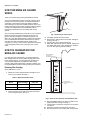
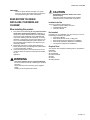
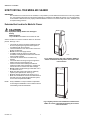
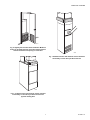
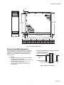
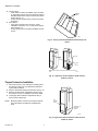
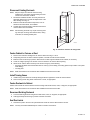
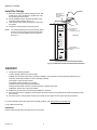
Media Air Cleaner INSTALLATION INSTRUCTIONS AND OWNER’S MANUAL Contents How Your Media Air Cleaner Works ............................................................................................................................................ How You Can Maintain Your Media Air Cleaner.......................................................................................................................... Read Before You Begin installing Your Media Air Cleaner .......................................................................................................... How to Install Your Media Air Cleaner......................................................................................................................................... 3 3 4 5 69-1866-01 MEDIA AIR CLEANER HOW YOUR MEDIA AIR CLEANER WORKS 2 Thank you for purchasing a Honeywell Media Air Cleaner. Your Honeywell Media Air Cleaner works by capturing small particles, such as dust and pollen, in between thousands of small fibers. These fibers provide high efficiency filtration while allowing air to pass with minimal resistance. Since your heating and cooling system relies on proper air flow to operate correctly, this feature allows improved filtration without impacting the performance of your heating and cooling system. The 4 inch deep pleated design of the filter in your Honeywell Media Air Cleaner also lasts significantly longer than the typical 1 inch filter it replaces. Compared to typical 1 inch filters, the 4 inch deep pleated design contains a lot more filter area. Increased filter area means that the filter can capture and hold more dust and particles before needing to be changed. As a result, you only need to replace the Honeywell 4 inch deep pleat air filter once or twice per year, in most cases. 1 M13640 Fig. 1. Removing air cleaner door. 4. 5. 6. 7. HOW YOU CAN MAINTAIN YOUR MEDIA AIR CLEANER Lift slightly upwards and remove door. Note direction “AIR FLOW” arrow on filter cartridge is pointing. See Fig. 2. Pull dirty filter out of cabinet and discard. Slide clean replacement filter into cabinet, making sure the “AIR FLOW” arrow on the cartridge is in the direction of air flow (pointing towards furnace). NOTE DIRECTION OF AIR FLOW (TOWARDS FURNACE) For optimum system performance, you should replace the filter cartridge every six months (before heating season and before cooling season). You may adjust the schedule to fit your particular application, but replace the filter at least annually. With regular replacement of the filter cartridge, your Honeywell Media Air Cleaner should provide years of service. AIR FLOW Make sure the air flow is in the direction of the arrow. 16 X 25 This Filter Fits: • • Replacing Filter Cartridge Honeywell 20x25 Air Cleaners ® ® Aprilaire Space-Gard Model 2200 Air Cleaners* FURNACE MERV (Every 6 Months to 1 year) 12 2.5 meters per second Choose better indoor air for your family by installing Honeywell solutions. You’ll enhance your comfort and peace of mind. 1. Obtain the correct replacement filter cartridge for your unit from your retailer. See Table 1. For information on installation of these solutions visit our website at www.honeywell.com/yourhome/ Ultraviolet Air Treatment System Zap airborne germs and prevent mold growth on air conditioning coils Whole-House Air Cleaner Trap a high percentage of airborne particles Whole-House Humidifier Moisturize parched air to minimize adverse health effects and protect woodwork in your home. Table 1. Replacement Filter Chart Zoning System Control temperature by area in your home, adding convenience and improving comfort Perfect Window™ Air Exchanger Ventilate your home to assure fresh air while minimizing energy loss Programmable Thermostat Media Air Cleaner Model RMAC1625 RMAC2025 2. 3. Replacement Filter Cartridge CF200A1008 CF200A1016 Save up to 30% in annual energy costs with this easy-to-use thermostat that’s accurate to within +/- 1 Replacement Filter Size Replace filters every 12 months, or more often if the filter appears dirty to the point of blocking air flow through the heating/cooling equipment. 1/1/2006 DATE INSTALLED: 16” X 25” WRITE FILTER INSTALLATION DATE HERE Sign up on our web site for free filter change reminder service. 20” x 25” www.honeywell.com/yourhome/ Disconnect power to your heating and cooling system. Grasp air cleaner door handle and pull firmly towards you to swing door open. See Fig. 1. ® ® *Aprilaire and Space-Gard are registered trademarks of Research Products Corporation. M13641 Fig. 2. Filter air flow direction and installation date. 8. 9. 10. 11. 69-1866—01 2 Record installation date in the space provided on the replacement filter cartridge. See Fig. 2. Insert the tab on the bottom of the door into the slot in the cabinet. Swing door closed and press it firmly into place. Reconnect power to your heating and cooling system. MEDIA AIR CLEANER IMPORTANT Failure to replace the filter cartridge on a regular basis may result in decreased system performance and possible damage to HVAC components. CAUTION Sharp Edges Installation Hazard. Can cause personal injury. Wear gloves and safety glasses when handling media air cleaner or sheet metal components. READ BEFORE YOU BEGIN INSTALLING YOUR MEDIA AIR CLEANER: Included in the Box This box contains the following items: — Media Air Cleaner Cabinet and Door — CF200 Media Air Filter — Instruction Manual When installing this product... 1. 2. 3. This product is intended only for very experienced doit-yourself or professional installers. Installation of this product requires disassembling and reassembling furnace duct work. Depending on the application this may require building metal duct transitions, re-routing ductwork, or cutting holes in the furnace cabinet. If you are not comfortable installing this product please contact a licensed HVAC installer to have this device professionally installed. Read these instructions carefully before beginning. Failure to follow them could damage the media air filter or cause a hazardous condition. Check the ratings given in the instructions and on the media air cleaner to make sure the product is suitable for your application. WARNING Not Included Depending on your installation you may need one or more of the following to install the air cleaner: — Duct Tape or Mastic — Sheet-metal Screws, Rivets, or Slip-joints — Sheet-metal Ducts (size depends on installation) — Sheet-metal Transitions (depends on installation) — Turning Vanes (depends on installation) Required Tools You will also need at least the following tools to complete the installation: Tin snips Screwdrivers Drill and drill bits Pliers Gloves Safety Glasses Can cause personal injury or equipment damage. Do not cut or drill into any air conditioning or electrical accessory. Disconnect furnace and accessory power supplies before installing or servicing media air cleaner. 3 69-1866—01 MEDIA AIR CLEANER HOW TO INSTALL YOUR MEDIA AIR CLEANER IMPORTANT: Due to differences in how furnaces are installed, it is impossible to provide detailed instructions that cover every installation. The following instructions provide general guidelines on installation of the Media Air Cleaner. It is the responsibility of the installer to determine how to properly install the Media Air Cleaner in accordance with local codes, standards, and accepted building practices. Determine Best Location for Media Air Cleaner CAUTION Equipment Damage Hazard. Can damage or destroy HVAC equipment. Only install Media Air Cleaner on the return air duct. Select a location to mount the media air cleaner on the return plenum. See Figs. 3 to 9. • The media air cleaner should be installed such that all of the air passing through the HVAC system is circulated through the air cleaner. • The best location is in the return air duct next to the blower compartment. • Do not mount in the supply air duct. • If installing media air cleaner in system with humidifier, avoid applications where water mist will reach the filter cartridge. • The media air cleaner can be mounted in any position. • The metal cabinet is strong enough to support the weight of furnace and evaporator coil. • Choose a location that is readily accessible for replacing the filter. Allow at least 26 in. clearance in front of the unit for removal of the filter cartridge. • Do not install in locations that get colder than -40° F or hotter than 140° F. • Make sure filter pressure drop will not negatively impact system performance. See Fig. 10. • Media air cleaner dimensions are given in Fig. 11. • Make sure the Media Air Cleaner is located at least 3 feet away from any ultraviolet air treatment system, such as the Honeywell RUVLAMP1. M13642 Fig. 3. Highboy furnace with side installation. Media air cleaner is mounted vertically where return enters side inlet of furnace. NOTE: Every installation is unique. Installer is responsible for ensuring that installation is in accordance with all local building codes and standards. M940A Fig. 4. Highboy furnace with installation beneath furnace. Media air cleaner is mounted horizontally where return enters from below. 69-1866—01 4 MEDIA AIR CLEANER M941A Fig. 5. Highboy furnace with closet installation. Media air cleaner is mounted vertically on furnace between furnace and louvered return air opening in closet door. M943A Fig. 7. Downflow furnace with media air cleaner mounted horizontally in return duct just above furnace. M942A Fig. 6. Lowboy furnace with media air cleaner mounted horizontally in return duct just above furnace and opposite heating duct. 5 69-1866—01 MEDIA AIR CLEANER M944A Fig. 8. Central return installation with media air cleaner mounted horizontally in central return duct. M945A Fig. 9. Horizontal furnace with media air cleaner mounted vertically in return duct near furnace. FILTER SIZE 20 X 25 16 X 25 0.300 PRESSURE DROP (IN. WC) 1 0.250 0.200 0.150 0.100 0.050 0.000 0 1 500 1000 AIRFLOW (CFM) 1500 2000 WHEN FIRST INSTALLED. PRESSURE DROP INCREASES AS FILTER BECOMES LOADED. REPLACE FILTER WHEN PRESSURE DROP REACHES 0.5 IN. WC. (0.1 kPa). M13644 Fig. 10. Pressure drop versus airflow of CF200A media filter. 69-1866—01 6 MEDIA AIR CLEANER 1 1 (29) 8 DIM. B (SEE TABLE) DIM. A (SEE TABLE) 3 6 4 (171) 7 5 8 (22) 8 (16) IN. DIM. D (SEE TABLE) RMAC SIZE MM 16 X 25 16 X 20 7 8 (22) DIM. C (SEE TABLE) 406 X 635 406 X 508 DIM. A DIM. B IN. MM 14 7/16 367 367 14 7/16 IN. MM 16 3/16 16 3/16 411 411 DIM. D DIM. C IN. MM 23 1/4 18 1/4 591 457 IN. MM 25 1/2 20 1/2 648 521 M13643 Fig. 11. Air cleaner dimensions. Determine Sheet-Metal Requirements The media air cleaner is adaptable to all new or existing for forced air heating and cooling systems used in residential applications. Some applications may require transitions, turning vanes, or duct offsets for proper installation of the media air cleaner. 1. DUCT SIZE CHANGED GRADUALLY TO PREVENT TURBULENCE. 20 DEGREE EXPANSION PER SIDE PER FITTING (4 IN. PER RUNNING FOOT [100 MM PER 300 LINEAR MM]) Transitions • Transitions are needed when the duct is a different size than the air cleaner cabinet. • Use gradual transitions to reduce air turbulence and increase efficiency. See Fig. 12. • Use no more than 20 degrees (about 4 in. per running foot) of expansion on each side of the transition fitting. RETURN AIR DUCT TRANSITION FITTING MEDIA AIR CLEANER CABINET M947B Fig. 12. Typical duct transitions. 7 69-1866—01 MEDIA AIR CLEANER 2. 3. Turning Vanes • If the media air cleaner is installed next to an elbow or angel fitting, add turning vanes inside the angle to distribute airflow more evenly across the face of the media. See Fig. 13. • Turning vanes must be properly secured to prevent movement. Duct Offsets • If the duct connection to the furnace in a side installation is less than 7 in. you will need to add an offset. See Fig. 14. • Turning vanes may be required to distribute air flow evenly. TURNING VANES M5651 Fig. 13. Turning vanes help distribute airflow evenly over media. OFFSET LESS THAN 7 in. (178 mm) 1 AT LEAST 7 in. (178 mm) 1 REQUIRED TURNING VANES HELP DISTRIBUTE AIRFLOW EVENLY. M948A Fig. 14. Typical use of duct offsets to make room for media air cleaner. Prepare Furnace for Installation 1. 2. 3. 4. Disconnect power to your heating and cooling system and remove power from any ultraviolet air treatment system that is installed. Remove and discard existing furnace filter. See Fig. 15. Remove furnace blower compartment access cover. See furnace owners' or installation manual for details. Thoroughly clean the blower compartment using a power vacuum (Shop-Vac). FAN ACCESS PANEL NOTE: Media Air Cleaner cannot remove dirt that has settled in the blower compartment and distribution ducts. EXISTING 1 IN. FURNACE FILTER M13645 Fig. 15. Typical use of duct offsets to make room for media air cleaner 69-1866—01 8 MEDIA AIR CLEANER Disconnect Existing Ductwork NOTE: Skip this step if the media air cleaner is being installed on a new system without existing duct that needs to be removed or modified. 1. 2. 3. Review the installation location and verify that there is adequate clearance for removal and replacement of the filter cartridge. See Fig. 16. Make sure that all sheet-metal components, such as transitions and duct offsets, are available. Carefully disconnect the existing ductwork where the air cleaner cabinet is to be installed. NOTE: Disconnecting ductwork may require removing existing duct tape, removing sheet metal screws, cutting metal duct, or breaking sealed joints. 26 IN. (637 MM) MINIMUM M13646 Fig. 16. Check for clearance to change filter. Fasten Cabinet to Furnace or Duct 1. 2. 3. 4. 5. Remove door and filter cartridge from air cleaner cabinet. See Figs. 1 and 2. Temporarily place the air cleaner cabinet in position, oriented as it will be when installed. Make sure unit sits securely in position. Place blocks or other support materials under cabinet, as necessary. Create or enlarge opening in the furnace or duct to match the air cleaner cabinet opening. Attach the air cleaner cabinet securely to the furnace using any of the following: • Drill holes and fasten with sheet metal screws or rivets. (If you are drilling, use locking pliers to help hold the unit in place while drilling.) • Use slip joints. NOTE: Make sure fasteners do not interfere with installation and removal of the filter. Install Turning Vanes 1. 2. Install turning vanes wherever an abrupt 90 degree elbow is against the media air cleaner cabinet. Secure turning vanes using sheet metal screws or rivets, as appropriate. Fasten Ductwork to Cabinet Fasten side of media air cleaner cabinet to ductwork using sheet metal screws, rivets, or slip joints, as appropriate. NOTE: Make sure fasteners do not interfere with installation and removal of the filter. Reconnect Existing Ductwork 1. 2. Connect remaining ductwork using sheet metal screws, rivets, or slip joints, as appropriate. Add support straps and bracing to prevent excessive movement. Seal Duct Joints 1. Seal all duct joints in the return air system between media air cleaner cabinet and the furnace. NOTE: Use only duct-rated metalized tape or mastic to seal duct connections. 9 69-1866—01 MEDIA AIR CLEANER Install Filter Cartridge 1. 2. 3. 4. Slide filter cartridge into cabinet, making sure the “AIR FLOW” arrow on the cartridge is in the direction of air flow (pointing towards furnace). Record installation date in the space provided on the replacement filter cartridge. See Fig. 17. Insert the tab on the bottom of the door into the slot in the cabinet. Swing door closed and press it firmly into place. NOTE: It is recommended that you use a permanent marker to draw an arrow showing the proper air flow direction on the top of the cabinet, for future reference. See Fig. 17. MARK AIR FLOW DIRECTION WITH PERMANENT MARKER AIR FLOW Make sure the air flow is in the direction of the arrow. 16 X 25 This Filter Fits: • • Honeywell 20x25 Air Cleaners ® ® Aprilaire Space-Gard Model 2200 Air Cleaners* NOTE DIRECTION OF AIR FLOW (TOWARDS FURNACE) MERV 12 FURNACE 2.5 meters per second Choose better indoor air for your family by installing Honeywell solutions. You’ll enhance your comfort and peace of mind. For information on installation of these solutions visit our website at www.honeywell.com/yourhome/ Ultraviolet Air Treatment System Zap airborne germs and prevent mold growth on air conditioning coils Whole-House Air Cleaner Trap a high percentage of airborne particles Whole-House Humidifier Moisturize parched air to minimize adverse health effects and protect woodwork in your home. Zoning System Control temperature by area in your home, adding convenience and improving comfort Perfect Window™ Air Exchanger Ventilate your home to assure fresh air while minimizing energy loss Programmable Thermostat Save up to 30% in annual energy costs with this easy-to-use thermostat that’s accurate to within +/- 1 Replace filters every 12 months, or more often if the filter appears dirty to the point of blocking air flow through the heating/cooling equipment. 1/1/2006 DATE INSTALLED: WRITE FILTER INSTALLATION DATE HERE Sign up on our web site for free filter change reminder service. www.honeywell.com/yourhome/ ® ® *Aprilaire and Space-Gard are registered trademarks of Research Products Corporation. M13647 Fig. 17. Install furnace filter and mark airflow direction. CHECKOUT 1. 2. 3. 4. Complete the following checklist: Filter cartridge inserts and removes easily. Make sure the “AIR FLOW” arrow on the filter cartridge is in the direction of air flow (pointing towards furnace). Turning vanes and transitions, if used, are properly installed. All joints in sheet-metal are sealed. All sheet-metal connections are complete. Ductwork is securely fastened and supported Original furnace filter has been removed and blower compartment is clean. Media air cleaner door is securely installed. Replace any access doors removed during installation or checkout. Reconnect power to the heating and cooling system and restore power to any ultraviolet air treatment system that was disconnected. Run the furnace or cooling system through one complete cycle to make sure the system operates as desired. For more information about Honeywell Indoor Air Quality products, visit: http://yourhome.honeywell.com or call:1-800-345-6770 x531 IMPORTANT Please read these instructions and keep them in your records. 69-1866—01 10 MEDIA AIR CLEANER Limited Warranty Honeywell warrants this product, excluding bulbs, to be free from defects in the workmanship or materials, under normal use and service, for a period of one (1) year from the date of purchase by the consumer. If, at any time during the warranty period, the product is defective or malfunctions, Honeywell shall repair or replace it (at Honeywell’s option) within a reasonable period of time. If the product is defective, return it, with a bill of sale or other dated proof of purchase, to the retailer from which you purchased it. This warranty does not cover removal or reinstallation costs. This warranty shall not apply if it is shown by Honeywell that the defect or malfunction was caused by damage which occurred while the product was in the possession of a consumer. Honeywell’s sole responsibility shall be to repair or replace the product within the terms stated above. HONEYWELL SHALL NOT BE LIABLE FOR ANY LOSS OR DAMAGE OF ANY KIND, INCLUDING ANY INCIDENTAL OR CONSEQUENTIAL DAMAGES RESULTING, DIRECTLY OR INDIRECTLY, FROM ANY BREACH OF ANY WARRANTY, EXPRESS OR IMPLIED, OR ANY OTHER FAILURE OF THIS PRODUCT. Some states do not allow the exclusion or limitation of incidental or consequential damages, so this limitation may not apply to you. THIS WARRANTY IS THE ONLY EXPRESS WARRANTY HONEYWELL MAKES ON THIS PRODUCT. THE DURATION OF ANY IMPLIED WARRANTIES, INCLUDING THE WARRANTIES OF MERCHANTABILITY AND FITNESS FOR A PARTICULAR PURPOSE, IS HEREBY LIMITED TO THE ONE YEAR DURATION OF THIS WARRANTY. Some states do not allow limitations on how long an implied warranty lasts, so the above limitation may not apply to you. This warranty gives you specific legal rights, and you may have other rights which vary from state to state. If you have any questions concerning this warranty, please write Honeywell Customer Relations, 1985 Douglas Dr. N MN101461, Golden Valley, MN 55422 or call 1-800-468-1502, Monday-Friday, 7:00 a.m. to 5:30 p.m., Central time. In Canada, write Honeywell Limited/Honeywell Limitée, 35 Dynamic Dr., ON15, Scarborough, Ontario M1V4Z. 11 69-1866—01 MEDIA AIR CLEANER Automation and Control Solutions Honeywell International Inc. Honeywell Limited-Honeywell Limitée 1985 Douglas Drive North 35 Dynamic Drive Golden Valley, MN 55422 Scarborough, Ontario M1V 4Z9 customer.honeywell.com ® U.S. Registered Trademark © 2009 Honeywell International Inc. 69-1866—01 E.K. Rev. 05-09