1
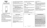
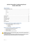
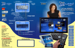
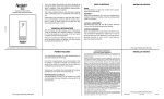
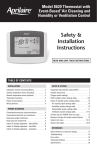
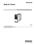
®
ELECTRONIC THERMOSTATS
MODEL 8353
5 - 2 Day Programmable
1 Heat / 1 Cool
Electric / Gas
User’s Manual
Installation and
Programming
Installation Guide
IMPORTANT SAFETY INFORMATION WARNING:
•
Always turn off power at the main power source by unscrewing
fuse or switching circuit breaker to the off position before installing,
removing, cleaning, or servicing thermostat.
•
Read all of the information in this manual before installing or
programming this thermostat.
•
This is a 24V AC low-voltage thermostat. Do not install on voltages
higher than 30V AC.
•
All wiring must conform to local and national building and electrical
codes and ordinances.
•
Do not short (jumper) across terminals on the gas valve or at the
system control to test installation. This will damage the thermostat
and void the warranty.
1
Features
• Four setpoints for weekday programming—two setpoints for
weekend comfort.
• Two “AA” ENERGIZER brand batteries retain program memory,
even during power outages.
• Low battery indicator.
• Fahrenheit/Celsius display option.
• Programmable from 45°F (4°C) to 90°F (32°C).
• Accuracy within ± 1 degree.
• Adjustable temperature differential: 1-3 degrees.
• Maintains summer and winter programming.
• Low temperature freeze protection. While in heat mode, thermostat
will mechanically turn on heat if temperature drops to 40°F (4°C) –
even if batteries are missing or drained.
• Automatic heating shutdown if temperature exceeds 90°F (32°C).
Replacing Existing Thermostat
1. Turn off power to heating and cooling system.
2. Remove cover of old thermostat to expose wires. Do not
disconnect wires. (Fig. 1)
3. Label wires per Table 1.
Table 1
Old Label
New Label
Description
M, 4, RH, R5 or R
RH
Heat Transformer,
hot side
V or RC
RC
Cooling Transformer, hot
side
Y or Y6
Y
Cooling control
H, W or 4
W
Heating control
F or G
G
C*
Y or None
Fan control relay
Either cooling control or
common side of transformer
*NOTE: On some older models, the C terminal can be either the coolingcontrol or the common side of the transformer. Check furnace wiring
diagram to verify C terminal. If it is the common side of the transformer,
cap the wire and tuck into the wall. If it is the cooling control, connect to
the Y terminal.
4. After labeling wires, remove wires from terminals.
5. Remove existing thermostat base from wall.
6. Refer to the following section for instructions on how to
install thermostat.
2
Figure 1
Installing the Model 8353 Thermostat
NOTE: For new installations, mount thermostat on inside wall, 4-5 feet
above the floor. Do not install behind a door, in a corner, near air vents,
in direct sunlight, or near any heat or steam generating fixtures.
Installation at these places will affect thermostat operation.
1. Turn power off to the heating and cooling systems.
2. Place COOL-OFF-HEAT In OFF position.
COOL-OFF-HEAT
PROG
>
>
MAN
SET PROG/MAN
COOL-OFF-HEAT
FAN: AUTO - ON
FAN: AUTO-ON
3. Place FAN: AUTO–ON switch
Into AUTO position.
4. Remove the cover using a coin
or screwdriver.
Figure 2
5. Place thermostat against the wall at desired location. Make sure
wires will feed through opening on base of thermostat.
6. Mark placement of mounting holes. See Fig. 3. Set base aside.
3
Figure 3
MOUNTING HOLES
AM
PM
PROG
MORN DAY EVE NITE
CHANGE
SET
RH
RC
MAN
W
Y
AUTO/MAN
G
COOL OFF HEAT
Elec
Gas
FAN AUTO ON
7. Drill the marked holes using a 3/16” drill bit. Note: Enclosed plastic
anchors do not require a drilled hole for drywall.
8. Tap plastic anchors into the wall.
9. Align base with plastic anchors and feed wires through opening.
See Fig 4.
Figure 4
AM
PM
PROG
RH
RC
MORN DAY EVE NITE
CHANGE
SET
MAN
W
Y
AUTO/MAN
G
COOL OFF HEAT
Elec
Gas
FAN AUTO ON
10. Secure base to wall with supplied screws.
11. Connect wires to terminal strip. Refer to wiring diagrams on other
side of this sheet. Make sure wire connections are secure.
12. Place fan option switch into either the “ELEC” or “GAS” position
depending upon the type of furnace. Refer to Figure 5.
Figure 5
AM
PM
PROG
RH
RC
MORN DAY EVE NITE
CHANGE
SET
MAN
W
Y
AUTO/MAN
G
COOL OFF HEAT
4
Elec
Gas
FAN AUTO ON
FAN
OPTION
SWITCH
Controls
fan delay.
13. Install two “AA” ENERGIZER brand batteries or equivalent into
battery compartment. Be sure to match positive (+) ends of batteries
with positive (+) battery terminals in the battery compartment. The
display will show as follows:
14. Replace cover onto thermostat by snapping into place.
15. Turn on power to system . Test thermostat as described in the
following section.
Programming Guide
Set Time of Day, Day of Week,
Temperature Differential
1. Press & Hold SET. Press PROG/MAN
Release simultaneously.
SET PROG/MAN
PROG
COOL-OFF-HEAT
FAN: AUTO - ON
>
to change
4. Press
>
3. Press
>
>
2. Press or
Time of Day.
SET P
>
SET PROG/MAN
>
>
>
MAN
To Change
Day of Week
5
1=MO
2=TU
3=WE
4=TH
5=FR
6=SA
7=SU
>
6. Press
>
5. Press
SET P
To change
Temperature Differential*
*The Temperature Differential is Factory preset at 1°. This means that
whenever the room temperature changes by one full degree from the
temperature setting, the system will turn on. If the system turns on too
often, increase the temperature differential.
7. Press SET to finish.
Changing Fahrenheit (F) to Celsius (C)
Press
>
Press and Hold SET
SET P
Release both simultaneously.
Setting Daily Programming
1. Place COOL-OFF-HEAT switch
in COOL position.
COOL-OFF-HEAT
PROG
>
>
MAN
SET PROG/MAN
COOL-OFF-HEAT
FAN: AUTO - ON
SET PR
3. Press
or
to change
MORN time in 30-minute
intervals.
6
>
>
>
>
2. Press SET.
4. Press SET.
SET PR
PROG
COOL-OFF-HEAT
FAN: AUTO - ON
>
SET PROG/MAN
>
>
>
MAN
>
>
5. Press or to change
MORN temperature.
6. Repeat Steps 2-5 for DAY, EVE, and NITE.
COOL-OFF-HEAT
7. Press SET to finish.
8. Shift COOL-OFF-HEAT switch to
HEAT position.
9. Repeat steps 2-7 to program HEAT (winter) settings.
NOTE: Both summer and winter programs use the same time settings.
Your thermostat is now programmed for summer and winter operation.
It will follow the four settings (MORN, DAY, EVE, NITE) for weekday
operation and two settings (MORN and NITE) for weekend operation.
Adjust the program at any time by following the steps as outlined above.
Begin Programmed Operation
1. Place FAN: AUTO–ON switch
Into AUTO.
FAN: AUTO-ON
PROG
>
>
MAN
SET PROG/MAN
COOL-OFF-HEAT
FAN: AUTO - ON
COOL-OFF-HEAT
SUMMER
2. Place COOL-OFF-HEAT switch
Into COOL or HEAT
Depending upon the season.
COOL-OFF-HEAT
3. Press PROG/MAN button
until indicator is in PROG position.
WINTER
ET PROG/MAN
PROG
>
>
MAN
SET PROG/MAN
COOL-OFF-HEAT
FAN: AUTO - ON
PROG
MAN
7
Temporary Program Override
>
>
or
>
Press
>
To temporarily increase or decrease temperature
PROG
>
>
MAN
SET PROG/MAN
COOL-OFF-HEAT
FAN: AUTO - ON
The thermostat will automatically return
to the program at the next scheduled
setting change or after four hours.
Manual Operation
Manual operation allows continuous override of the program settings.
1. Press PROG/MAN until indicator is in MAN position.
PROG
PROG
MAN
MAN
COOL-OFF-HEAT
FAN: AUTO - ON
>
>
2. Press
or to adjust
temperature settings.
>
SET PROG/MAN
>
>
>
T PROG/MAN
Reset
To reset the thermostat to factory pre-programmed
conditions, press the reset button located directly
to the right of the display.
AM
PM
PROG
MORN DAY EVE NITE
CHANGE
SET
MAN
AUTO/MAN
RESET
BUTTON
RH
RC
W
Y
Elec
Gas
G
COOL OFF HEAT
8
FAN AUTO ON
To Test Thermostat
WARNING: DO NOT SHORT (JUMPER) ACROSS TERMINALS OF GAS
VALVE OR SYSTEM CONTROL TO TEST OPERATION. THIS WILL DAMAGE THE THERMOSTAT AND VOID YOUR WARRANTY.
CAUTION: Do not switch system to cool if the temperature is below
50°F (10°C). This can damage the air conditioning system and cause
personal injury.
COOL-OFF-HEAT
1. Place the COOL-OFF-HEAT
switch into the COOL position
>
2. Press the button until the temperature
setting is at least 3 degrees below the room temperature. The
air conditioning system should turn on within a few seconds.
NOTE: There is a built in 5-minute delay on break for compressor
protection. A second attempt to turn on the air conditioning will
result in a 5-minute delay in compressor activation.
3. Put the COOL-OFF-HEAT switch into
the OFF position. The air conditioning
system should turn off. The fan may
continue to run for a short period of time.
COOL-OFF-HEAT
>
4. Put the COOL-OFF-HEAT switch
into the HEAT position.
COOL-OFF-HEAT
5. Press the button until the temperature setting is at least
3 degrees above room temperature. The heating system should
turn on. The fan may not turn on immediately, depending upon
the fan delay built into the furnace.
6. Put the COOL-OFF-HEAT switch
into the OFF position. The heating
system should turn off. Once again,
the fan may have a delay.
7. Put the FAN: AUTO–ON switch
to the ON position. The blower
fan should turn on.
COOL-OFF-HEAT
FAN: AUTO - ON
8. Put the FAN: AUTO–ON switch
to the AUTO position. The blower
fan should turn off.
9
FAN: AUTO-ON
Troubleshooting
Symptom
Thermostat does not turn
on system
Remedy
Check Wiring
(see INSTALLATION).
Check fuse. Replace with 2 amp
Slo-Blo fuse if fuse has opened.
Thermostat turns on and off too
frequently.
Increase Temperature Differential
(see PROGRAMMING).
Display is blank, flashing or
constant “LO BAT.”
Replace batteries.
Weekend Program follows four
adjustment settings.
Verify that day of week is set
correctly (see PROGRAMMING).
System fan does not operate
properly.
Move fan option switch to either
gas or electric, to match system
(see INSTALLATION).
Time shown on display is not the
current time of day.
Change time of day setting
(see PROGRAMMING).
Thermostat does not
follow program.
Thermostat in MANUAL mode
(see PROGRAMMING).
Thermostat may not have been
programmed in HEAT or COOL
position. Verify program.
Check AM/PM indicators at time
of day and programmed time
changes (see PROGRAMMING).
Verify program and day of week
is correct (see PROGRAMMING).
If problems with thermostat cannot be solved, call:
Technical Support: 608-257-8801
Monday-Friday 7:45 am - 5:00 pm CST
10
Wiring Diagrams
The following is just a sample of the most common types of HVAC systems. Refer to your systems installation manual for wiring information.
HEAT ONLY
3-WIRE
SINGLE TRANSFORMER
HEAT/COOL
4-WIRE
SINGLE TRANSFORMER
Factory- Installed
jumper
Factory-Installed
jumper
RH
Transformer
RC
Hot
120 VAC
24 VAC
Heating
Control
W
Cooling
Control
Y
Fan
Control
G
T
H
E
R
M
O
S
T
A
T
RH
Transformer
Hot
120 VAC
RH
RC
24 VAC
Heating
Control
W
Y
G
NOTE: Remove factory
installed jumper
T
H
E
R
M
O
S
T
A
T
(HEATING)
Transformer
120 VAC
RH
24 VAC
RC
Hot
120 VAC
24 VAC
Heating
Control
W
Cooling
Control
Y
Fan
Control
G
T
H
E
R
M
O
S
T
A
T
G
T
H
E
R
M
O
S
T
A
T
COOL ONLY
3-WIRE
SINGLE TRANSFORMER
RH
Transformer
Hot
120 VAC
RC
24 VAC
W
HEAT/COOL
5-WIRE
TWO TRANSFORMER
Hot
W
Y
Fan
Control
NOTE: Remove factory
installed jumper
Hot
120 VAC
24 VAC
Heating
Control
HEAT ONLY
2-WIRE
SINGLE TRANSFORMER
Transformer
RC
NOTE: Cut center of
factory installed jumper
and bend back
NOTE: Both transformers
must be in phase.
(COOLING)
Transformer
11
Cooling
Control
Y
Fan
Control
G
T
H
E
R
M
O
S
T
A
T
Limited Warranty
Your Research Products Corporation Aprilaire® Thermostat unit is expressly
warranted for two (2) years from date of installation to be free from defects in
materials and workmanship.
Research Products Corporation’s exclusive obligation under this warranty shall
be to supply, without charge, a replacement for any thermostat which is found
to be defective within a two (2) year period and which is returned, together with
the date of installation, no later than thirty (30) days after said two (2) year
period by you to either your original supplier or to Research Products
Corporation, Madison, Wisconsin 53701.
THIS WARRANTY SHALL NOT OBLIGATE RESEARCH PRODUCTS CORPORATION FOR ANY LABOR COSTS AND SHALL NOT APPLY TO DEFECTS IN
WORKMANSHIP OR MATERIALS FURNISHED BY YOUR INSTALLER AS CONTRASTED TO DEFECTS IN THE THERMOSTAT ITSELF.
IMPLIED WARRANTIES OF MERCHANTABILITY OR FITNESS FOR A PARTICULAR PURPOSE SHALL BE LIMITED IN DURATION TO THE AFORESAID
TWO YEAR PERIOD. RESEARCH PRODUCTS CORPORATION’S LIABILITY
FOR INCIDENTAL OR CONSEQUENTIAL DAMAGES, OTHER THAN DAMAGES
FOR PERSONAL INJURIES, RESULTING FROM ANY BREACH OF THE AFORESAID IMPLIED WARRANTIES OR THE ABOVE LIMITED WARRANTY IS
EXPRESSLY EXCLUDED. THIS LIMITED WARRANTY IS VOID IF DEFECT(S)
RESULT FROM FAILURE TO HAVE THIS THERMOSTAT INSTALLED BY A
QUALIFIED HEATING AND AIR CONDITIONING CONTRACTOR. IF THE
LIMITED WARRANTY IS VOID DUE TO FAILURE TO USE A QUALIFIED
CONTRACTOR, ALL DISCLAIMERS OF IMPLIED WARRANTIES SHALL BE
EFFECTIVE UPON INSTALLATION.
Some states do not allow limitations on how long an implied warranty lasts or
the exclusion or limitation of incidental or consequential damages, so the
above exclusion or limitations may not apply to you.
This warranty gives you specific legal rights and you may also have other rights
which vary from state to state.
P.O. BOX 1467 • MADISON, WI 53701-1467
Products For Better Indoor Air Quality ™
B2202517 REV. 12/00
12