1
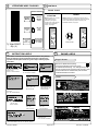
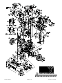
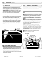
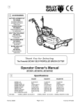
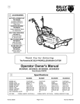
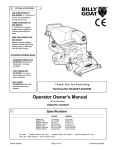
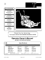
1
ACCESSORIES
2
NUT REPLACEMENT KIT
P/N 500208.
To replace stripped or
damaged insert nuts in
engine base.
BLADE BC2401
P/N 500210.
Original Equipment Blade
for replacement.
BELT TRACTION DRIVE
P/N 500119.
Traction Drive Belt
for BC2401
BELT BLADE DRIVE
P/N 500237.
Blade Drive Belt
for BC2401
BLADE HIGH LIFT
BC2401
P/N 500102.
Optional blade for
replacement
Thank You for Selecting
The Powerful BC2401 SELF-PROPELLED BRUSH CUTTER
Operator Owner's Manual
BC2401IC, BC2401H, BC2401HE
Specifications
3
ENGINE: H.P.
ENGINE: TYPE
ENGINE MODEL NO:
ENGINE: FUEL CAP.
ENGINE: OIL CAP.
WEIGHT: UNIT
WEIGHT: SHIPPING
ENGINE WEIGHT:
MAX. OPERATING SLOPE
UNIT SIZE:
Part No. 500264
BC2401IC
BC2401H
BC2401HE
10.5 (7.83 kW)
B&S
28B702118-E1
3.0 qt. (2.84 L)
1.34 qt. (1.41 L)
282# (128.5 kg)
310# (141.3 kg)
66.0# (30.0 kg)
15°
11 (8.20 kW)
HONDA
GXV340K1DX3
2.3 qt. (2.18 L)
1.20 qt. (1.13 L)
278# (126.1 kg)
306# (138.8 kg)
70.5# (32.0 kg)
20°
11 (8.20 kW)
HONDA
GXV340K1DE33
2.3 qt. (2.18 L)
1.20 qt. (1.13 L)
282# (127.9 kg)
310# (140.6 kg)
72.5# (32.9 kg)
20°
OVERALL LENGTH: 82.5"(2.09 m)
OVERALL WIDTH 32.0" (0.81m)
Page 1 of 12
OVERALL HEIGHT43" (1.09m)
Form No. F101001A
5
IN THE INTEREST OF SAFETY
BEFORE STARTING ENGINE, READ AND UNDERSTAND THE “ENTIRE OPERATOR'S MANUAL &
ENGINE MANUAL.”
THIS SYMBOL MEANS WARNING OR CAUTION. DEATH, PERSONAL INJURY AND/OR PROPERTY
DAMAGE MAY OCCUR UNLESS INSTRUCTIONS ARE FOLLOWED CAREFULLY.
WARNING: The Engine Exhaust from this product contains chemicals known
to the State of California to cause cancer, birth defects or other reproductive harm.
WARNING: DO NOT
laws apply on federal lands.
& /or damage to unit.
13. DO NOT tamper with governor springs,
1. DO NOT run engine in an enclosed
governor links or other parts which may
area. Exhaust gases contain carbon
monoxide, an odorless and deadly poison. change the governed engine speed.
14. DO NOT tamper with the engine speed
selected by the engine manufacturer.
2. DO NOT place hands or feet near
moving or rotating parts.
3. DO NOT store, spill or use gasoline
near an open flame, or devices such as a
stove, furnace, or water heater which use
a pilot light or devices which can create a
spark.
4. DO NOT refuel indoors where area is
not well ventilated. Outdoor refueling is
recommended.
5. DO NOT fill fuel tank while engine is
running. Allow engine to cool for 2
minutes before refueling. Store fuel in
approved safety containers.
6. DO NOT remove fuel tank cap while
engine is running.
7. DO NOT operate engine when smell of
gasoline is present or other explosive
conditions exist.
8. DO NOT operate engine if gasoline is
spilled. Move machine away from the spill
and avoid creating any ignition until the
gasoline has evaporated.
9. DO NOT transport unit with fuel in tank.
10. DO NOT smoke when filling fuel tank.
11. DO NOT choke carburetor to stop
engine. Whenever possible, gradually
reduce engine speed before stopping.
12. DO NOT run engine at excessive speeds. This may result in
injury
6
15. DO NOT check for spark with spark plug
or spark plug wire removed. Use an
approved tester.
16. DO NOT crank engine with spark plug
removed. If engine is flooded, place throttle
in “FAST” position and crank until engine
starts.
17. DO NOT strike flywheel with a hard
object or metal tool as this may cause
flywheel to shatter in operation. Use proper
tools to service engine.
18. DO NOT operate engine without a
muffler. Inspect periodically and replace, if
necessary. If engine is equipped with
muffler deflector, inspect periodically and
replace, if necessary, with correct deflector.
19. DO NOT operate engine with an
accumulation of grass, leaves, dirt or other
combustible material in the muffler area.
20. DO NOT use this engine on any forest
covered, brush covered, or grass covered
unimproved land unless a spark arrester is
installed on the muffler. The arrester must
be maintained in effective working order by
the operator. In the State of California the
above is required by law (Section 4442 of
the California Public Resources Code).
Other states may have similar laws. Federal
7
Part No. 500264
TEMPERATURE:
WIND DIRECTION:
OPERATOR
Sunny
HUMIDITY:
BAROMETRIC PRESSURE:
25. DO NOT park machine on a steep grade
or slope.
WARNING: DO
1. ALWAYS DO remove the wire from the
spark plug when servicing the engine or
equipment TO PREVENT ACCIDENTAL
STARTING.
2. DO keep cylinder fins and governor
parts free of grass and other debris
which can affect engine speed.
3. DO pull starter cord slowly until resistance is felt. Then pull cord rapidly to avoid
kickback and prevent hand or arm injury.
4. DO examine muffler periodically to be
sure it is functioning effectively. A worn or
leaking muffler should be repaired or
replaced as necessary.
5. DO use fresh gasoline. Stale fuel can
gum carburetor and cause leakage.
6. DO check fuel lines and fittings frequently
for cracks or leaks. Replace if necessary
7. Follow engine manufacturer operating
and maintenance instructions.
8. Inspect machine and work area before
starting unit.
VIBRATION
Vibration levels at the operators handles were
measured in the vertical, lateral, and longitudinal
directions using calibrated vibration test equipment.
Tests were performed on 05/19/95 under the
conditions listed:
Sunny
GENERAL CONDITION:
62 °F (16.7 °C)
5 MPH (8 kmh)
WIND SPEED:
23. DO NOT operate during excessive
vibration!
24. DO NOT leave machine unattended
while in operation.
VIBRATION LEVEL 1.1g
SOUND TESTS
GENERAL CONDITION:
22. DO NOT run engine without air cleaner
or air cleaner cover.
8
Sound tests conducted were in accordance
with 79/113/EEC and were performed on 05/19/
95 under the conditions listed:
TABLE OF CONTENTS
SAFETY INSTRUCTIONS
2
GENERAL SAFETY
3
ASSEMBLY
3
LIT. BAG & CONTROLS
4
4
LABELS
OPERATION
5, 9
10 - 12
MAINTENANCE
PARTS DRAWING & LIST
6-8
12
TROUBLESHOOTING
WARRANTY PROCEDURE
12
SOUND
21. DO NOT touch hot muffler, cylinder, or
fins because contact may cause burns.
South
67%
30.06" Hg (763mm Hg)
Page 2 of 12
72 °F (22.2 °C)
TEMPERATURE:
5 MPH (8 kmh)
WIND SPEED:
S.W.
WIND DIRECTION:
67 %
HUMIDITY:
30.06" Hg (763mm Hg)
BAROMETRIC PRESSURE:
Form No. F101001A
9
GENERAL SAFETY
For your safety and the safety of others, these directions should be followed:
Do not operate this machine without first reading
owner's manual and engine manufacturer's manual.
Use of Ear Protection is recommended while
operating this machine.
Use of Eye and Breathing protection is recommended when using this machine.
·DO NOT place hands or feet beneath cutting deck, near
debris outlet or near any moving parts.
·DO NOT start engine or operate unit with bystanders in or
near the work area.
·DO NOT start or operate machine with blade or drive clutch
engaged.
10
ASSEMBLY
Read all safety and operating instructions
before assembling or starting this unit.
PUT OIL IN ENGINE BEFORE STARTING.
DISCONNECT SPARK PLUG WIRE
BEFORE ASSEMBLING UNIT.
Your Billy Goat Brush Cutter is shipped from the
factory in one carton, completely assembled except
for the upper handle, and front guard bar.
11
·DO NOT operate during excessive vibration.
·DO NOT perform any maintenance or inspection until engine has
been turned off and has come to a complete stop, and the spark
plug has been removed
·DO NOT operate machine with guards removed.
·DO NOT use this machine for cutting areas containing rock,
glass, string like material, wire, rags, cans, metal, or other nonorganic material.
·DO NOT operate this machine on slopes greater than specified
on page 1.
·DO NOT operate machine near any hot or burning debris, or any
toxic or explosive material.
·DO NOT allow children to operate this equipment.
1. REMOVE unit from carton and allow upper handle (item 40) to lay on
ground behind unit. Set guard bar(Item 31) to the side for now.
2. REMOVE hardware items 115, 117, 141, 143, & 144 from temporary
storage positions on lower handle (items 51, & 52).
3. ATTACH upper handle to lower as shown below, and securely tighten
all fasteners. For easy alignment of handles during installation, loosen the
four screws that secure the lower handles. Line up and hand tighten all
handle hardware before final tightening. Note: Be sure the engine starter
rope is properly installed in the starter rope guide (item 145) before
tightening the corresponding fasteners.
4. REMOVE hardware items 102, 103, 117, 119, 124, 141, & 152 from
temporary storage positions on deck and skid assy at front of unit
(items 2, 155, & 156)
5. ATTACH guard bar(Item 31) to deck as shown below. Install the center
bolts(Item 153) first, and install the bolts that fasten through the sides of
the deck last. Securely tighten all fasteners. Note: Hardware items 117,
119, & 141 are used to secure both the front skid attachment and the
sides of the guard bar. Be sure both are securely attached.
6. CONNECT spark plug wire to spark plug.
PACKING CHECKLIST
These items should be included in your carton. If
any of these parts are missing, contact your dealer.
Per Model
Handle Upper
Assembly
500256
Bar Support WA
500235
Literature
Assy
Literature Assy
500263
Briggs & Stratton
Engine
Manual
Honda(English)
Honda W/Electric
Start (English)
Part No. 500264
Page 3 of 12
Form No. F101001A
12
LITERATURE ASSY P/N 500263
13 CONTROLS
Literature Checklist
Ty Wrap 900407
Qty: (4)
14
Owner's
Manual
Owner's
Manual
Warranty
Card
Warranty
Card
400972
EU Declaration
of Conformity
& EU
Distributor List
500264
Throttle Control
BRIGGS &
STRATTON
HONDA
Briggs engines have a choke
type carburetor that is
operated by moving the
throttle control to the full start
position. See STARTING
section, see page 5.
EU Declaration
of Conformity &
EU Distributor
List 500265
Honda engines have a separate choke lever that is
operated by pulling back along with moving the throttle
control to the full start position if necessary. See
STARTING section, see page 5.
Pull to choke
INSTRUCTION LABELS
15
These labels should be included on your Brush Cutter. If any of these
labels are damaged, replace them before putting this equipment into
operation. Item and part numbers are given to help in ordering replacement labels..
ENGINE LABELS
Briggs & Stratton
Read Owner’s Manual Before Operating.
Lire le manuel d’utilisation avant la mise en route.
Label Do Not Fill While
Engine Is Hot
Item 63 Part No.400268
Vor Inbetriebnahme Bedienungs - und Wartungsanleitung lesen.
Favor leer las instrucciones de operacion
' antes de operar el motor.
Label Ear Eye Breathing Item
No. 188 Part No. 890254
Label Warning Guards
Item 185 Part No.900327
Consultare il Manuale' Uso e Manutenzione prima dell 'utilizzo.
.. ..
Las Skotselinstruktionen Innan Start.
Honda
Label Danger Keep Hands and
Feet Away
Item 180 PartNo.400424
Label Danger Flying
Material Item 184
Part No.810736
Label Read Owner's
Manual Item No. 187
Part No. 890301
Label Shift BC2400
Item No. 186
Part No. 500202
Label Clutch Blade
Item 192
Part No.500177
Label Clutch Drive
Item 191
Part No.500176
Label Patent No
Item 190 Part No.500279
Label Chock Wheels Item No. 189 Part No. 500168
Part No. 500264
Page 4 of 12
Form No. F101001A
OPERATION
16
INTENDED USE: This is not a lawn mower. The BC2401 is
designed for cutting overgrown weeds, brush, and other
types of organic growth to a height of 3-1/2". The unit may
also be used to clear small saplings 1-1/2" in dia. or less. It
does not provide the cut quality of a finish cut lawn mower.
The unit is designed for use in rural areas, and should not
be used in settings where conditions require that the unit be
operated in tight or confined areas. Be sure to inspect work
area and machine before operating. Make sure that all
operators of this equipment are trained in general machine
use and safety.
Like all mechanical tools, reasonable care must
be used when operating machine. Do not operate unit
in areas where bystanders may be present.
Do not operate if excessive vibration occurs. If excessive
vibration occurs, shut engine off immediately and check for
damaged or worn blade, loose blade bolt, loose blade adapter
key, loose engine or lodged foreign objects. Note: See parts list
for proper blade bolt torque specifications. (See trouble shooting
section on page 12).
16.1
NOTE: Do not engage blade during transport between work
sites. The blade should remain disengaged at all times when
work is not being performed.
The best performance is achieved when cutting in dry
conditions. If the deck becomes choked with grass or debris
during operation, back unit off of debris allowing machine to
clear itself and continue cutting, or shut the unit off and clear the
clog by hand (See below). A drop in engine RPM or a noticeable change in engine sound is usually a good indicator of a
clogged discharge or other interference.
Under most conditions cutting should be done in first or
second gear. Third gear should be reserved for conditions
where weeds and brush are thinned out or not as tall. The
quality of the cut produced is directly related to the unit's ground
speed during cutting. If the quality of the cut is not satisfactory
(i.e. material left standing) you should shift into a lower gear
during cutting. For improved control in confined areas, this
machine can be pushed forward or backward by releasing the
operator's clutch lever, placing the transaxle in neutral, and
pushing the machine.
CLEARING A CLOGGED CUTTING DECK:
Turn engine off and wait for blade to stop completely.
Disconnect spark plug wire. Wearing durable gloves,
remove clog.
Danger, the clog may contain sharp materials.
Reconnect spark plug wire.
STARTING
PUT OIL IN ENGINE BEFORE STARTING.
ENGINE: See engine manufacturer’s instructions
for type and amount of oil and gasoline used.
Engine must be level when checking and filling oil and
gasoline.
BLADE CLUTCH
ENGINE SPEED: Controlled by throttle lever on the handle.
FUEL VALVE: Move fuel valve to "ON" position (when
provided on engine).
The Brush Cutter blade clutch is controlled by an operator
presence control. To engage the blade, depress the operator's
left hand control lever against operator's handle. The blade is
disengaged by releasing this lever.(See Fig. 1.1)
NOTE: The blade clutch must be either fully engaged for cutting
or fully disengaged to bring the blade to a stop. Do not operate
the unit with the blade clutch partially engaged. Premature belt
wear and clutch failure will result from improper operation of the
clutch.
CAUTION: Use extreme care when operating the
blade. Inspect the work area for foriegn objects
that could cause damage to the unit or injure the
operator if struck by the blade. Never operate the
blade with bystanders in the work area.
CHOKE:
Briggs engines have a choke type carburetor that is
operated by moving the throttle control to the full start
position.
Honda engines have a separate choke lever that is operated by pulling back when starting. Push it back to its
original position after the engine has started.
THROTTLE: Move remote throttle control to fast position.
Pull starting rope to start engine.
ELECTRIC START: Choke the engine if necessary. Push
and hole down on the rocker switch until engine starts, then
release switch to run.
Lever Up
Disengages
Clutch
Handle
IF YOUR UNIT FAILS TO START:
See Troubleshooting on page 12.
16.2
Lever
CUTTING OPERATION
Lever
Down
Engages
Clutch
GENERAL OPERATION: To engage the blade, depress
the operator's left hand control lever against operator's handle.
The blade is disengaged by releasing this lever.(See Fig. 1.1)
To engage the wheel drive, lift the operator's right hand
control lever against operator's handle. The drive is disengaged by releasing this lever.(See Fig. 1.2) Ground speed can
be varied by shifting gears as described on page 9. To begin
cutting engage the blade lever, allow the blade to spin up to
speed, and engage the wheel drive to begin moving forward
into the material to be cut.
Part No. 500264
Page 5 of 12
Fig. 1.1
Form No. F101001A
18
PARTS DRAWING
BC2401HE, BC2401H, BC2401IC
Part No. 500264
Page 6 of 12
Form No. F101001A
19
PARTS
LIST
ITEM
NO.
1
2
3
4
5
6
7
8
DESCRIPTION
Deck Assembly with labels
Deck WA BC2401
Deflector Front BC2400
Base Assembly with labels
Handle Brace Left
Handle Brace Right
Door Base Engine
Transaxle 3 SPD BC2400
BC2401HE
Part No
500239
500266
500125
500240
500196
500200
500233
500100
QTY
1
1
1
1
1
1
1
1
BC2401H
Part No
500239
500266
500125
500240
500196
500200
500233
500100
QTY
1
1
1
1
1
1
1
1
BC2401IC
Part No
QTY
500239
1
500266
1
500125
1
500240
1
500196
1
500200
1
500233
1
500100
1
9
10
11
12
13
14
15
16
17
18
Pulley 5.0" OD ‘A’ Sec.
Belt Traction Drive
Plate Pivot Idler / Shifter
Shifter Pivot WA
Pulley Idler
Wheel & Tire 16" AG SP LH
Wheel & Tire 16" AG SP RH
Arm Idler WA
Cable Clutch Blade BC2400
Cable Clutch Drive BC2400
830180
500119
500122
500169
800260
500103
500104
500170
500259
500327
1
1
1
1
1
1
1
1
1
1
830180
500119
500122
500169
800260
500103
500104
500170
500259
500327
1
1
1
1
1
1
1
1
1
1
830180
500119
500122
500169
800260
500103
500104
500170
500259
500327
1
1
1
1
1
1
1
1
1
1
19
20
21
22
23
24
25
26
27
28
Bar Shift T-axle
Angle Support T-axle
Rod Link Shifter
Tube Shift With Grip
Clutch Brake BC2401
Grip 3/4 ID - Black
Tube Pointer
Plate Mount Idler WA
Pulley Idler 4.5" OD X 3/8
Hub Cap
500121
500127
500144
500171
500258
610102
500184
500228
500270
900486
1
1
1
1
1
1
1
1
1
2
500121
500127
500144
500171
500258
610102
500184
500228
500270
900486
1
1
1
1
1
1
1
1
1
2
500121
500127
500144
500171
500258
610102
500184
500228
500270
900486
1
1
1
1
1
1
1
1
1
2
29
30
31
32
33
34
35
36
37
38
Belt Blade Drive
Spacer Spindle BC2401
Bar Guard WA BC2401
Bushing Shifter
Washer Hub Cap
Spindle WA BC2400
Bearing 7/8" ID Sealed Press
Shaft Drive Blade
Spacer Spindle Bearing
Pulley 7" OD x 7/8" BORE
500237
500232
500235
500130
850237
500174
500101
500107
500115
500253
1
1
1
1
2
1
2
1
1
1
500237
500232
500235
500130
850237
500174
500101
500107
500115
500253
1
1
1
1
2
1
2
1
1
1
500237
500232
500235
500130
850237
500174
500101
500107
500115
500253
1
1
1
1
2
1
2
1
1
1
39
40
41
42
43
44
45
46
Lever Control Blade
Handle Upper BC2400
Grip Handle 1 ID x 7.5
Lever Control Clutch
Bushing Lever Control
Fitting Mount Cable
Engine 11 HP Honda GXV340 Electric Start
Engine 11 HP Honda GXV340
Engine 10.5 HP B & S I/C
Pulley Drive Traction BC2401
500312
500243
500267
500142
500152
500187
500294
500238
1
1
2
1
4
2
1
1
500312
500243
500267
500142
500152
500187
620100
500238
1
1
2
1
4
2
1
1
500312
500243
500267
500142
500152
500187
500323
500238
1
1
2
1
4
2
1
1
47
48
49
50
51
52
53
54
55
56
Spacer Engine WA 2401
Control Throttle BC2400
Tube Cable Cover
Blade 24" BC2400
Handle Lower RH BC2400
Handle Lower LH BC2400
Adapter Blade WA
Washer Friction Blade
Guard Hand BC2401
Screwcap 8x3/8 HWH Type B
500262
500154
500186
500210
500140
500141
500191
500108
500257
100121
1
1
2
1
1
1
1
1
2
2
500262
500154
500186
500210
500140
500141
500191
500108
500257
100121
1
1
2
1
1
1
1
1
2
2
500262
500213
500186
500210
500140
500141
500191
500108
500257
100121
1
1
2
1
1
1
1
1
2
2
100
101
102
103
104
105
106
107
108
Washer Lock 5/16 Twist. Tooth
Bolt Carraige 1/4 - 20 x 3/4
Nut Lock 1/4 - 20
Screw Cap 5/16 - 18 x 1 1/4
Washer Lock 5/16 split
Plate Impeller Washer
Screw Cap 7/16-20 X 3"
SCREWCAP 5/16-18 X 1"
Screw Cap 5/16 - 18 x 2 3/4
8177011
8024021
*8160001
*8041029
*8177011
850443
500269
*8041028
*8041035
2
4
14
18
7
1
1
5
6
8177011
8024021
*8160001
*8041029
*8177011
850443
500269
*8041028
*8041035
2
4
10
18
7
1
1
4
6
8177011
8024021
*8160001
*8041029
*8177011
850443
500269
*8041028
*8041035
2
4
10
18
7
1
1
4
6
109
110
111
Bolt Carraige 5/16 - 18 x 3/4
Washer Flat 1/2"
Pin Cotter 3/32 x 3/4"
8024039
900230
*8197016
2
1
1
8024039
900230
*8197016
2
1
1
8024039
900230
*8197016
2
1
1
Part No. 500264
Page 7 of 12
Form No. F101001A
19
Parts List
continued from
page 9.
* Denotes
standard
hardware item,
that may be
purchased
locally.
Item
No.
112
113
114
115
116
117
118
119
120
121
122
123
124
125
126
127
128
129
130
131
132
133
134
135
136
137
138
139
140
141
142
143
144
145
146
147
148
149
150
151
152
153
154
155
156
157
158
159
160
161
162
163
164
165
166
167
168
169
180
184
185
186
187
188
189
190
191
192
193
194
195
Part No. 500264
Description
Bolt Shoulder 1/2 x 1
Nut Lock 3/8-16
Bolt Idler
Screw Cap 5/16 x 2"
Nut Jam 5/16 - 18
Nut Lock 5/16 - 18
Bolt Carraige 5/16 - 18 x 1
Screw Cap 5/16 x 1 1/2
Washer 3/8 FC
Terminal Piggyback 3/16
Screw Cap 1/4 - 28 x 1/2 GR5
Washer Lock 1/4 Split
Washer 1/4 FC
Screw Self Tap 5/16
Pin Hair Cotter
Washer 5/16 SAE
Screw Cap 1/4 - 20 x 2 1/2
Washer 3/4 SAE
Washer 0.765 x 1.250 x 0.060
Plate Control Box
Ring Snap 0.750
Key 3/16 x 2 1/8
Washer Fender 1/4"
Screw Cap 7/16 - 20 x 1 1/4 GR8
Washer 1.25 x 0.882 x 0.125
Ty Wrap
Key Sq 3/16 x 5/8
Screw Cap 7/16 - 20 x 2 GR8
Washer Lock 7/16 Tw. Tooth
Washer 5/16 FC
Bracket Clutch Cable Guard
Screw Cap 5/16 - 18 x 1 3/4
Screw Cap 5/16 - 18 x 2 1/2
Guide Rope
Grip Lever
Label Start/Stop Toggle
Spacer Engine Honda SP VQ
Guide Belt LH
Guide Belt RH
Screw Cap 5/16 - 24 x 1
Screw Cap 1/4 - 20 x 1 1/4
Screw Cap 1/4 - 20 x 2 3/4
Screwcap 1/4-20 x 2”
Skid RH BC v-cup WA
Skid LH BC v-cup WA
Switch Box Assy BC
Switch Toggle
Harness Assy
Bushing Strain Relief
Label Throttle
Cable Battery Red W/Charge
Cable Battery Black 10"
Lid Box Battery
Box Battery Drilled
Plate Guard Bottom Battery
Strap Battery
Bracket Mount Battery Wa
Bar Support Battery
Label OPEI
Label Flying Debris
Label Guards
Label Shift BC2400
Label Read
Label Ear Eye Breathe
Label Chock Wheels
Label Patent No
Label Clutch Drive
Label Clutch Blade
Plate cChoke Mount BC
Screw Machine 10-24x5/8"
Control Cable Choke BC
BC2401HE
Part No.
500114
*8160003
800888
*8041032
*8142002
*8160002
*8024040
*8041030
*8171004
890010
850408
*8177010
*8171002
*8123128
900471
*8172008
*8041012
*8172015
850238
500305
850230
9201087
8172019
800554
500182
900407
9201072
500188
850132
*8171003
500321
*8041031
*8041034
830533
500181
500329
830113
500230
500231
*400164
*8041007
*8041013
*8041010
500291
500292
500318
500307
500306
500282
810656
500304
790133
500301
Qty.
500299
500303
500302
500297
500298
400424
810736
900327
500202
890301
890254
500168
500279
500176
500177
1
1
1
1
1
2
1
2
1
1
1
1
1
1
1
Page 8 of 12
1
3
1
5
3
29
6
4
1
1
1
1
5
1
2
2
1
2
2
1
2
2
4
1
1
4
2
1
3
27
1
7
1
2
2
1
1
1
1
2
7
1
2
1
1
1
1
1
1
1
1
1
1
BC2401H
Part No.
500114
*8160003
800888
*8041032
*8142002
*8160002
*8024040
*8041030
*8171004
890010
850408
*8177010
*8171002
*8123128
900471
*8172008
*8041012
*8172015
850238
500305
850230
9201087
Qty.
Qty.
1
3
1
5
3
28
6
4
1
1
1
1
5
1
2
2
1
2
2
1
2
2
BC2401IC
Part No.
500114
*8160003
800888
*8041032
*8142002
*8160002
*8024040
*8041030
*8171004
850408
*8177010
*8171002
*8123128
900471
*8172008
*8041012
*8172015
850238
850230
9201087
800554
500182
900407
9201072
500188
850132
*8171003
500321
*8041031
*8041034
830533
500181
1
1
4
2
1
3
27
1
7
1
2
2
800554
500182
900407
9201072
500188
850132
*8171003
500321
*8041031
*8041034
830533
500181
1
1
4
2
1
3
23
1
9
1
2
2
830113
500230
500231
*400164
*8041007
*8041013
*8041010
500291
500292
500283
500281
890442
500282
810656
1
1
1
2
3
1
2
1
1
1
1
1
1
1
830113
500230
500231
*400164
*8041007
*8041013
*8041010
500291
500292
500283
500281
890442
500282
810656
1
1
1
2
3
1
2
1
1
1
1
1
1
1
400424
810736
900327
500202
890301
890254
500168
500279
500176
500177
500325
8059135
500326
2
1
2
1
1
1
1
1
1
1
1
1
1
400424
810736
900327
500202
890301
890254
500168
500279
500176
500177
500325
8059135
500326
2
1
2
1
1
1
1
1
1
1
1
1
1
1
3
1
5
3
30
6
4
1
1
1
5
1
2
2
1
2
2
2
2
Form No. F101001A
OPERATION
16
16.3
continued
16.5
PROPULSION
This Brush Cutter is self-propelled, and is controlled by an
operator presence control. To engage the wheel drive, lift the
operator's right hand control lever against operator's handle. The
drive is disengaged by releasing this lever.(See Fig. 1.2)
GROUND SPEED can be varied by selecting a higher or lower
gear using the gear shift lever at the rear of the machine(See
Fig. 2), or by changing the engine rpm. To shift the Brush
Cutter into reverse, release all controls and rotate the shift lever
to the left, when the lever stops lift it up and continue to turn it to
the left until it stops again.
Under most conditions cutting should be done in first or second
gear. Third gear should be reserved for conditions where
weeds and brush are thinned out or not as tall. The quality of
the cut produced is directly related to the unit's ground speed
during cutting. If the quality of the cut is not satisfactory (i.e.
material left standing) you should shift into a lower gear during
cutting. For improved control in confined areas, this machine
can be pushed forward or backward by releasing the operator's
clutch lever, placing the transaxle in neutral, and pushing the
machine.
Using three people to lift machine is recommended. Lift holding the
handle and front of deck. Secure in place during transport.
16.6
STORAGE
Never store engine indoors or in enclosed poorly ventilated
areas with fuel in tank, where fuel fumes may reach an open
flame, spark or pilot light, as on a furnace, water heater, clothes
dryer or other gas appliance.
If engine is to be unused for 30 days or more, prepare as
follows:
Be sure engine is cool. Do not smoke. Remove all gasoline
from carburetor and fuel tank to prevent gum deposits from
forming on these parts and causing possible malfunction of
engine. Drain fuel outdoors, into an approved container, away
from open flame. Run engine until fuel tank is empty and
engine runs out of gasoline.
NOTE: Fuel stabilizer (such as Sta-Bil) is an acceptable
alternative in minimizing the formation of fuel gum deposits
during storage. Add stabilizer to gasoline in fuel tank or storage
container. Always follow mix ratio found on stabilizer container.
Run engine at least 10 min. after adding stabilizer to allow it to
reach the carburetor.
Lever Up
Engages
Clutch
Handle
HANDLING & TRANSPORTING:
CAUTION: Wheels must be chocked or blocked
when unit is parked on a slope.
SHIFT LEVER
Lever
Fig. 1.2
16.4
CUTTING HEIGHT ADJUSTMENT
Cutting height can be adjusted to allow a 1” lower cutting height.
This is particularly useful for cutting grasses that lay over when
over grown. (i.e. Bermuda, Johnson, etc.)
Fig. 2
Note: When cutting brush and normal field grasses it is
strongly recommended that you operate your brush cutter at the
standard (top) cutting height.
Part No. 500264
Page 9 of 12
Form No. F101001A
MAINTENANCE
17
17.2
Use only a qualified mechanic for
any adjustments, disassembly or
any kind of repair .
BELT REPLACEMENT
When replacing one belt the other should be inspected for wear and
replaced if worn. It is good practice to change both belts when either
is worn beyond use. Use only original equipment belts for replacement. Billy Goat uses only premium quality, kevlar corded and coated
belts in your unit. Substitute belts do not meet the design and
performance requirements for your unit , and will greatly reduce
machine performance and belt life.
WARNING: TO AVOID PERSONAL INJURY, ALWAYS
TURN MACHINE OFF, MAKE SURE ALL MOVING
PARTS COME TO A COMPLETE STOP.
Transaxle Drive Belt
DISCONNECT SPARK PLUG WIRE
BEFORE SERVICING UNIT.
RECONNECT SPARK PLUG WIRE,
AND ALL GUARDS BEFORE STARTING ENGINE.
Note: Blade, and drive belts are normal wear items.
These should be inspected on a regular basis and
replaced if worn.
ENGINE
When servicing engine refer to specific manufacturers engine
owner's manual. All engine warranty is covered by the specific
engine manufacturer. If your engine requires warranty or other
repair work contact your local servicing engine dealer. When
contacting a dealer for service it is a good idea to have your
engine model number available for reference(See table page 11).
If you can not locate a servicing dealer in your area you can
contact the manufacturers national service organization.
To reach:
Briggs & Stratton: 800-233-3723
American Honda: 800-426-7701
17.1
BLADE REMOVAL / SHARPENING
Tools required: 1/2 inch socket, 1/2 inch universal extension bar, pry
bar or long screw driver, adequate support for machine.
1. Disconnect spark plug wire.
2. Support rear of unit to allow access to underside of the machine
towards the rear. Note: Unit is heavy. Be sure support is adequate to
prevent personal injury.
3. Loosen but do not remove the two nuts (116) holding the plate mount
idler (item 26) in place. This will release the tension on the blade drive
belt (29). NOTE: It may be necessary to apply some force to the pulley
to slide it over from it’s tight position and release the belt.
4. Working from the underside of the machine, loosen but do not
remove the four screws (103) holding the two belt guides(Items 149 &
150) in place next to the crankshaft drive pulley (9) at the rear of the
machine. This will loosen the belt guides(Items 149 & 150) and allow
them to move to the side. NOTE: This step requires the use of a
universal joint or universal extension bar to reach the screws(103)
holding the belt guide(149). If universal joint is not available you may
remove the “neutral stop bolt”(Item 115) and associated nuts (116 &
117) to allow the idler arm to swing back and allow access to the
screws(103) holding the belt guide(149).
5. With the guides loose slip the transaxle drive belt(Item 10) out of the
groove on the drive pulley and down past the pulley.
6. Slip the old belt(10) up and over the pulley on the transaxle (Item 9)
and remove belt from machine.
7. Install new belt in groove on transaxle pulley(Item 9) and slip into
groove on transaxle drive pulley(46).
8. Tighten four screws(103) to secure belt guides(149 & 150) in place.
Note: With clutch levers engaged, be sure belt guides do not touch
belts after installation.
9. Reconnect spark plug wire.
Blade Drive Belt
NOTE: When sharpening the blade it is a good idea to check the
balance of the blade. A properly balanced blade will increase
life of the bearings and other components.
Tools required: 5/8 inch socket, torque wrench, adequate
support.
1. Disconnect spark plug wire.
2. Support front of unit to allow access to the blade. Note: Unit
is heavy. Be sure support is adequate to prevent personal injury.
3. Block the blade to prevent it from rotating during removal.
4. Remove the blade bolt (Item 139), lockwasher (140), and
large friction washer (54).
5. Remove the blade (50) and, replace or sharpen the blade.
NOTE: When replacing the blade use only B.G.I. Part no.
500210.
6.Replace the blade using all fasteners in the exact order
they were removed. Torque blade screw to 60 ft-lbs. NOTE:
Before installing the fasteners inspect them for wear and
replace as necessary.
Part No. 500264
Tools required: 1/2 inch socket, 1/2 inch universal extension bar, pry bar
or long screw driver, adequate support for machine.
1. Disconnect spark plug wire.
2. Support rear of unit to allow access to underside of the machine
towards the rear. Note: Unit is heavy. Be sure support is adequate to
prevent personal injury.
3. Remove the two screws (103) and washers (141) holding the engine
base door (7), and remove the door.
4. Loosen but do not remove the two nuts (116) holding the plate mount
idler (item 26) in place. This will release the tension on the blade drive
belt (29). NOTE: It may be necessary to apply some force to the pulley
to slide it over from it’s tight position and release the belt.
5. Working from the underside of the machine, loosen but do not remove
the four screws (103) holding the two belt guides(Items 149 & 150) in
place next to the crankshaft drive pulley (9) at the rear of the machine.
This will loosen the belt guides(Items 149 & 150) and allow them to
move to the side. NOTE: This step requires the use of a universal joint
or universal extension bar to reach the screws(103) holding the belt
guide(149). If universal joint is not available you may remove the
“neutral stop bolt”(Item 115) and associated nuts (116 & 117) to allow
the idler arm to swing back and allow access to the screws(103) holding
the belt guide(149).
Page 10 of 12
Form No. F101001A
17
MAINTENANCE
continued
Blade Drive Belt
6. With the guides loose slip the blade drive belt(29) out of the groove
on the drive pulley and down past the pulley. Note: It is necessary to
remove the transaxle drive belt(10) from its groove to allow removal of
the blade drive belt.
7. Pull the belt back through the hole in the top of the engine base
and remove it from the machine. NOTE: Removal of the belt from the
blade drive pulley requires some force to walk the belt past the front
portion of the pulley.
8. Install new belt into groove on blade drive pulley. Push remaining
length of belt back through engine base toward clutch/brake drive
pulley.
9. Reach through from rear of machine and pull new belt through and
install it in the groove on the clutch/brake drive pulley. NOTE: Make
sure the blade belt is properly seated in the clutch/brake drive
pulley(Item 23) and not resting in the gap between the clutch/brake
pulley(23) and the transaxle drive pulley(46)
10. Tighten four screws to secure belt guides (item 149 & 150) in
place. NOTE: Be sure belt is correctly routed when replacing. (See
Fig. 3)
11. Set tension on belt by reaching in through top of engine base with
a long screwdriver or other pry bar and pushing the idler pulley over
against the belt to increase tension. While holding the belt under
tension tighten the two screws (107) that hold the idler arm in place.
Note: Proper belt tension can be verified by checking the tight side
(non-idler side)belt deflection. The belt should deflect 3/16”-1/4” with
force applied perpendicular to the belt after tensioning.
12. Replace engine base door (item 7) and tighten screws to hold it in
place
13. Reconnect spark plug.
Belt in top groove
of engine pulley
Transaxle
Drive Belt
Belt in bottom groove
of engine pulley
Fig. 3
BLADE DRIVE BELT TENSION ADJUSTMENT
Maintenance Schedule
1. Disconnect spark plug wire.
2. Remove the two screws holding the engine base door (item 7),
and remove the door.
3. Examine the condition of the belt and note the position of the idler
assembly and the amount of tension on the blade belt.
3. Loosen the two nuts (Item 117) on top of the engine base, holding
the idler arm assembly (Item 26) in place .
4. Reset tension on belt by reaching in through top of engine base
with a long screwdriver or other pry bar and pushing the idler pulley
over against the belt to increase tension. While holding the belt
under tension tighten the two screws that hold the idler arm in place.
5. Replace engine base door and verify blade belt tension setting by
operating the unit in the conditions that caused it to slip
originally.NOTE: If belt continues to slip it may be worn out and
require replacement before proper operation can resume.
Maintenance Operation
Follow these hourly
maintenance intervals.
Every Every 5 hrs Every 25 Every 50
or (Daily)
hrs
hrs
Use
Engine (See Engine Manual)
Check for excessive vibration
Inspect for loose parts
Inspect for worn or damaged parts
Sharpen Blade
Inspect belts for wear
Check blade clutch cable tension
Replace blade and traction belts
Inspect battery for damage or leak
Check battery terminal for corrosion
STARTER SWITCH WIRING
Lubricate throttle control cable and
linkage.
MAINTENANCE HISTORY
Date of Service
Part No. 500264
Page 11 of 12
Service Performed
Form No. F101001A
MAINTENANCE
17
continued
CLUTCH ADJUSTMENT
17.3
Clutch/Brake Adjustment:
As the clutch/brake wears, adjustments may be required to
maintain proper control cable tension, and clutch engagement.
If the clutch/brake begins slipping or squealing during normal
operation it may require an adjustment to increase the clutch
cable tension. A properly adjusted blade clutch should require a
minimum of 10 lbs. of force to completely depress the end of the
clutch lever.(See Fig. 4) Adjust by tightening or by loosening
clutch cable adjusting nut as required, located at the rear of the
engine base. When adjusting cable tension on blade control
cable be sure to leave slack in cable to allow for engagement of
blade brake. Replacement of cable or clutch/brake may be
necessary if adjustment will not allow for proper clutch and
brake engagement.
WARNING: If the clutch begins to squeal or slip, do not
continue to operate your unit until adequate adjustment or repair
has been performed.
Improper adjustment can cause clutch to slip and overheat,
greatly reducing machine performance and clutch life.
20
TROUBLESHOOTING
Problem
MINIMUM FORCE = 3 LBS.
WHEN FULLY DEPRESSED
MOVE ADJUSTER OUT TO
INCREASE CABLE TENSION
MOVE ADJUSTER IN TO
DECREASE CABLE TENSION
Fig. 4
Before Requesting Service Review These Suggestions
Possible Cause
Solution
The engine will not start
Stop switch is off. Throttle is not in ON position. Out of gasoline. Bad
or old gasoline. Spark plug wire disconnected. Dirty air cleaner.
Check switch, throttle, & gasoline. Check for spark with an approved
tester. Clean or replace air cleaner. Contact service dealer.
Starter does not turn
(Electric start unit only)
Battery is too low or dead. Battery cable is disconnected or battery
terminal is corroded. Bad starter switch or wire harness. Bad starter.
Charge battery or replace with a new one. Clean battery terminals.
Replace starter switch. Replace Wire harness. Contact service dealer.
The engine will not stop
Damaged stop switch. Stop switch wire is disconnected. Stop switch
wire is worn or damaged.
Replace stop switch. Connect stop switch wire. Replace stop switch
wire.
Will not cut or has poor
cutting performance.
Dull Blade. Clogged deck. Excessive quantity of debris built up or
blocking blade. Engine RPM set too low.
Unclog deck (see page 5). Sharpen blade.
Check engine RPM.(see page 11 for settings)
Abnormal vibration.
Loose or out of balance blade or loose engine.
Check blade and replace if required. Check Engine.
Belt slips or smokes.
Belt tension too low . Belt worn or stretched. Pulleys worn or
damaged.
Increase tension at idler(see page 11). Replace belt. Replace
pulleys
Clutch slips or squeals.
Clutch cable tension too low . Clutch worn or damaged.
Increase clutch cable tension (see above). Replace clutch/brake
Blade brake will not engage.
Inadequate slack in clutch cable . Clutch worn or damaged.
Adjust or replace cable (see above). Replace clutch/brake
No self propelling.
Operator's clutch lever not releasing clutch. Broken or out of
adjustment clutch cable. Worn or broken belt.
Adjust clutch cable. Replace any worn, damaged or malfunctioning
parts.
Self propelled drive will not
release .
Engine is locked, will not
pull over.
Clutch cable out of adjustment.
Adjust clutch cable. See page 12 Clutch Adjustment.
Debris locked against blade. Engine problem.
Remove debris (see page 5 ). Contact an engine servicing dealer
for engine problems.(see page 10)
22.1
21
WARRANTY PROCEDURE
Engine Service and Warranty
Contact your nearest engine manufacturer's authorized
servicing dealer.
Record your machine model, serial number and
date-of-purchase and where purchased
Serial Plate
22
Please fill in the WARRANTY CARD and send the upper part to Billy Goat.
The WARRANTY terms are stated on the lower part which remains with the
user. Whenever a Billy Goat Machine is faulty due to a defect in material
and / or workmanship, the owner should make a warranty claim as follows:
The Machine should be taken to the dealer from whom it was
purchased or to an authorized Billy Goat dealer.
The owner should present the remaining half of the Warranty
Registration Card, or, if this is not available, the invoice or receipt.
Model
The Warranty Claim will be filled in by the authorized Billy Goat Dealer,
who will send it with the faulty part to Billy Goat headquarters.
Serial No.
The Quality / Service department at Billy Goat headquarters will study
the claim and parts and will notify their conclusions.
Unit(Weight)
lbs.
kg
Part No. 500264
kW
rpm
min-1
Operator
Purchase
Date
The decision by the Quality / Service department at Billy Goat
headquarters to approve or reject a Warranty claim is final and
binding.
Engine Power
Note:
To process a Warranty Claim, it is necessary to quote the Model
& Serial number who are printed on the Billy Goat Serial Plate.
BILLY GOAT INDUSTRIES INC.
1803 S.W. JEFFERSON STREET LEE'S SUMMIT, MO 64082 / USA
PHONE: 816-524-9666 FAX: 816-524-6983
www.billygoat.com
Purchased
from
Page 12 of 12
Form No. F101001A
Gardening Supply
Patio Barbecues
Outdoor Barbecues
Landmann Barbecues
Gas Barbecues UK
Charcoal Barbecues
Brush Cutters
Gas Barbecues
Brushcutters
Cheap Gas Barbecues
Blower Vacs
Masonry Barbecues
Chain Saws
Chainsaws
Cultivators
Cylinder Lawn Mowers
Echo Chainsaws
Echo Strimmers
Electric Chainsaws
Fertiliser Spreaders
Garden Blowers
Garden Rollers
Lawn Rollers
Garden Shredders
Garden Tractors
Garden Vacuums
Hayter Lawn Mowers
Hedge Cutters
Hover Mowers
Husqvarna chainsaws
Kawasaki Brush Cutters
Hedgecutters
Kawasaki
Strimmers
Lawn Mowers
Scarifiers
Lawn Tractors
Leaf Vacuums
Ride on mowers
Electric Garden
Shredders
Petrol Chainsaws
Rotary Mowers
Petrol Garden
shredders
Leaf Blowers
Ride on lawn
Petrol Hedge Cutters
mowers
Rotavators
Ryobi Strimmers
Cheap Garden
ALKO Garden Shredders Shredders
Garden Patio Heaters
Outdoor Patio Heaters
Gas Patio Heaters
Patio Heater Covers
Garden Heaters
Greenhouse Heaters
Patio Heaters
Green house
heaters
Gas Greenhouse
heaters
Stainless Steel Patio
Heaters
Table Top Patio Heaters
Patio Heaters UK
Grit Spreaders
Patio Heaters with
Covers
Gardena Hedgecutters
Christmas Gardening
Gifts
Kawasaki brushcutters
Petrol Strimmers
Midgeater Plus
Barbecues
Cylinder Mowers