1
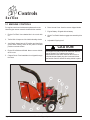
OWNER OPERATORS MANUAL 6" and 8" Chipper Models 74824 8" 24 HP Chipper with Hydraulic Feed 72620 6" 20 HP Chipper with Hydraulic Feed 71620 6" 20 HP Chipper Crary Company A Division of TerraMarc Industries 237 12th St. NW P.O. Box 849 West Fargo, ND 58078-0849 (701)282-5520 FAX: (701)282-9522 www.bearcatproducts.com www.terramarc.com Manual P/N 13987-00 Rev. 02/03 Companion to 13988-00 Before you Begin DEAR BEAR CAT CUSTOMER, Thank you for purchasing a Crary Bear Cat product. The Bear Cat line is designed, tested, and manufactured to give years of dependable performance. To keep your machine operating at peak efficiency, it is necessary to adjust it correctly and make regular inspections. The following pages will assist you in the operation and maintenance of your machine. Please read and understand this manual before operating. If you have any questions or comments about this manual, please call us toll-free at 1-800-2477335. If you have any questions or problems with your machine, please call or write your local factory-authorized Bear Cat dealer. How to Contact Bear Cat A D D R E S S Crary Bear Cat 237 NW 12th Street PO Box 849 West Fargo, ND 58078 P PLEASE SEND US YOUR WARRANTY CARD A warranty card is included in your owner's kit packaged with your machine. Please take the time to fill in the information requested on the card. When you send your completed card to us, we will register your machine and start your coverage under our limited warranty. H O N E 800-247-7335 701-282-5520 Fax: 701-2829522 EM A I L [email protected] [email protected] H O U R S M-F, 8 a.m. to 5 p.m. Central Time EMISSION INFORMATION WARNING WARNING TO ALL CALIFORNIA AND OTHER STATES OPERATING OUTDOOR POWER EQUIPMENT Under California Law and under the laws of several other states you are not permitted to operate an internal combustion engine using hydrocarbon fuels on any forest covered, brush covered or grass covered land or on land covered with grain hay or other I flammable agricultural crop, without an engine spark arrester in continuous effective working order. The engine on your power equipment, like most outdoor power equipment, is an internal combustion engine that burns gasoline, a hydrocarbon fuel. Therefore, your power equipment must be equipped with a spark arrester muffler in continuous effective working order. The spark arrester must be attached to the engine exhaust system in such a manner that flames or heat from the system will not ignite flammable material. violation of other state and or federal regulations, laws, ordinances, or codes. Contact your local fire marshal or forest service for specific information about what regulations apply in your area. The standard muffler installed on the engine is not equipped with a spark arrester. One must be added before use if this machine is intended to be used in an area where a spark arrester is required by law. Contact the local authorities if these laws apply to you. See your authorized engine dealer for spark arrester options. Failure of the owner/operator of the equipment to comply with this regulation is a misdemeanor under California law, and may also be a 6" and 8" Bear Cat Chipper Operators Manual Limited Warranty Crary Bear Cat chippers are warranted for 1 year from date of sale for consumers , commercial, or rental operations. Within the above stated period, Crary Co. will replace any part(s) found to be defective in material and/or workmanship, after the receipt of the part in our plant. Labor costs to replace these defective parts will be paid at a Crary established labor rate and time allowed (flat rate) for repair. All transportation charges incurred in shipping part(s) are the responsibility of the purchaser. This warranty is void in the case of accidents, failure to perform normal maintenance, or failure to follow those instructions listed in the service manual. This warranty is also in lieu of all other expressed warranties and voids any implied warranty as to the merchantability or fitness of the product for a particular purpose and of any other obligation on the part of Crary Co. Some states do not allow limitations on how long the implied warranty lasts, so the above limitation may not apply to you. This warranty applies only to parts or components that are defective, and does not cover necessary repair due to normal wear, misuse, accidents, or lack of proper maintenance. This includes belts, pulleys, and chipper blades. Regular routine maintenance of the unit to keep it in proper operating condition is the responsibility of the owner. All warranty repair reimbursable under the Crary Co. warranty must be performed by an authorized Bear Cat service dealer using Bear Cat approved replacement parts. Repair or attempted repair by anyone other than an authorized Bear Cat service dealer is not reimbursable under the Crary Co. warranty. In addition, these unauthorized repair attempts may result in additional malfunction, the correction of which is not covered by warranty. Crary Co. is not liable for indirect, incidental, or consequential damages in connection with the use of this product including any cost or expense or providing substitute equipment or service during periods of malfunction or non-use. Some states do not allow the exclusion of incidental or consequential damages, so the above exclusion may not apply to you. This warranty gives you specific legal rights. You may also have other rights that vary from state to state. Be sure to note the serial number in any correspondence with Crary Co. or any authorized Bear Cat dealer. Crary Company A Division of TerraMarc Industries 237 12th St. NW P.O. Box 849 West Fargo, ND 58078-0849 (701)282-5520 FAX: (701)282-9522 www.bearcatproducts.com www.terramarc.com 6" & 8" Bear Cat Chipper Operators Manual II CONTENTS SAFETY .......................................................................................................................................................................... 1 1.1 THE SAFETY ALERT SYMBOL ................................................................................................................................ 1 1.2 BEFORE OPERATING .............................................................................................................................................. 1 1.3 BEFORE OPERATING .............................................................................................................................................. 2 1.4 OPERATION SAFETY ............................................................................................................................................... 2 1.5 MAINTENANCE AND STORAGE SAFETY ............................................................................................................... 3 1.6 TOWING SAFETY ..................................................................................................................................................... 3 1.7 BATTERY SAFETY ................................................................................................................................................... 3 ASSEMBLY .................................................................................................................................................................... 4 2.1 ASSEMBLING THE MACHINE .................................................................................................................................. 4 2.2 INSTALLING THE BATTERY ...................................................................................................................................... 5 CONTROLS .................................................................................................................................................................... 6 3.1 MACHINE CONTROLS .............................................................................................................................................. 6 OPERATION ................................................................................................................................................................... 7 4.1 STARTING THE MACHINE ........................................................................................................................................ 7 4.2 STOPPING THE ENGINE .......................................................................................................................................... 8 4.3 CHIPPING ................................................................................................................................................................. 8 4.4 ROTATING THE CHIPPER BASE .............................................................................................................................. 8 4.5 HYDRAULIC FEED OPERATION (MODELS 72620 & 74824) .................................................................................... 9 4.6 CONTROL ARM OPERATION (MODELS 72620 & 74824) ......................................................................................... 9 4.7 HYDRAULIC FEED COMPONENT LOCATIONS (MODELS 72620 & 74824) ............................................................ 9 SERVICE & MAINTENANCE ......................................................................................................................................... 10 5.1 SHARPENING CHIPPER BLADES ......................................................................................................................... 10 5.2 SETTING CHIPPER BLADE CLEARANCE .............................................................................................................. 11 5.3 ADJUSTING DRIVE BELTS ..................................................................................................................................... 11 5.4 REPLACING DRIVE BELTS .................................................................................................................................... 12 5.5 CLEARING PLUGGED ROTOR ............................................................................................................................... 12 5.6 REPAIRING OR REPLACING ROTOR BEARINGS .................................................................................................. 13 5.7 GREASEABLE BEARINGS AND PIVOTS .............................................................................................................. 13 5.8 OTHER SERVICE TIPS ........................................................................................................................................... 13 5.9 TRAILER SERVICE TIPS ........................................................................................................................................ 13 5.10 HYDRAULIC FLUID (MODELS 72620 & 74824) ..................................................................................................... 14 5.11 PUMP COMPONENT LOCATIONS (MODELS 72620 & 74824) ............................................................................. 14 5.12 HYDROSTATIC PUMP START UP PROCEDURE (MODELS 72620 & 74824) ........................................................ 14 5.13 HYDRAULIC FEED MAINTENANCE (MODELS 72620 & 74824) ........................................................................... 15 5.14 ADDING HYDRAULIC FLUID........................................................................ .................................................... 15 TROUBLESHOOTING .................................................................................................................................................. 16 6.1 GENERAL TROUBLESHOOTING ............................................................................................................................ 16 6.2 HYDROSTATIC PUMP TROUBLESHOOTING (MODELS 72620 & 74824) ............................................................... 17 SPECIFICATIONS ........................................................................................................................................................ 18 7.1 SPECIFICATIONS ................................................................................................................................................... 18 7.2 BOLT TORQUE ....................................................................................................................................................... 19 III 6" & 8" Chipper Bear Cat Operators Manual 1 Safety Section 1.1 THE SAFETY ALERT SYMBOL This is the safety alert symbol. It is used in this Owner / Operators Manual and on your machine to alert you to potential hazards. Whenever you see this symbol, read and obey the safety message that follows it. Failure to obey the safety message could result in personal injury, death or property damage. DANGER Indicates an imminently hazardous situation that, if not avoided, will result in death or serious injury. WARNING Indicates a potentially hazardous situation that, if not avoided, could result in death or serious injury. CAUTION Indicates a potentially hazardous situation that, if not avoided, may result in minor or moderate injury. 1.2 BEFORE OPERATING 1. Read this Owner / Operators manual. Be completely familiar with the controls and the proper use of this equipment. 4. Familiarize yourself with all of the safety and operating decals on this equipment and on any of its attachments or accessories. 7. Do not run this equipment in an enclosed area. Do not operate this equipment in or near buildings, windows, or air conditioners. 5. Do not allow children or any person unfamiliar with the use of the unit to use this machine. 8. If needed, always use an approved fuel container. Keep open flames, sparks, smoking materials, and other sources of combustion away from fuel. 6. Keep the area of operation clear of all persons, particularly small children. Keep bystanders at least 50 feet (15 meters) away from the area of operation. 2. Before inspecting or servicing any part of the machine, wait for all parts to stop moving. Be aware that rotating parts slow down gradually after power is stopped. 9. Do not operate this machine if you are under the influence of alcohol, medications, or substances that can affect your vision, balance, and judgement. Do not operate if tired or ill. You must be in good health to operate this machine safely. 3. Keep safety decals clean and legible. Replace missing or illegible safety decals. 6" & 8" Bear Cat Chipper Operators Manual Page 1 Safety 1.3 BEFORE OPERATING 10. Wear safety glasses at all times while operating this machine. 11. Use only in daylight or good artificial light. 12. Never use without proper guards in place. 13. Avoid wearing loose fitting clothing. Never operate this machine wearing clothing with drawstrings that could wrap around or get caught in the machine. 14. Check that all screws, nuts, bolts, and other fasteners are properly se- cured before starting the machine. Check all screws, nuts, bolts, and other fasteners for proper tightness to ensure everything is in proper working condition once every 10 hours of operation. 15. Keep all guards, deflectors, and shields in place and in good working condition. 16. Do not transport or move machine while the machine is running. 1.4 OPERATION SAFETY WARNING Material can kickup or shift suddenly and cause serious injury or death. Wear eye and hearing protection. DANGER Keep hands, feet and clothing out of inlets and discharge openings while machine is operating to avoid serious personal injury. 1. Do not allow hands or any part of body or clothing near any moving part. 2. Exclude pieces of metal, rocks, bottles, cans, and other foreign objects from entering the machine. Page 2 3. Shut off machine immediately if the cutting mechanism strikes any foreign object or the machine starts making an unusual noise or vibrating. Allow the machine to stop completely. After machine stops: A. Inspect for damage. B. Replace or repair any damaged parts. C. Check for and tighten any loose parts. 4. Stand clear of the discharge area when operating this machine. 5. Keep your face and body back from the feed opening. 6. Do not climb on machine when operating. Keep proper balance and footing at all times. 7. Keep the machine clear of debris and other accumulations. 6" & 8" Bear Cat Chipper Operators Manual 8. Set up your work site so you are not endangering traffic and the public. Take great care to provide adequate warnings. 9. Ensure debris does not blow into traffic, parked cars, or pedestrians. 10. Check the bolts for correct torque every 10 hours of operation. 11. Shut off engine and allow machine to stop completely before clearing debris if the machine becomes clogged. Safety 1.5 MAINTENANCE AND STORAGE SAFETY NOTE If equipped, see engine owners manual or contact the engine manufacturer for engine safety instructions and decals. 1.6 TOWING SAFETY 1. Rotate the discharge tube to face the opposite direction of the towing vehicle before towing. This prevents the discharge tube from projecting over the trailer wheels and striking foreign objects. 2. Connect hitch safety chains. Tighten and secure trailer hitch bolts. Do not attempt to tow the trailer if vehicle is not equipped with a 2 ball. 1. Replace any missing or unreadable safety decals. Refer to the parts manual for part numbers when ordering safety decals from an area Bear Cat dealer. 2. Store the machine out of reach of children and where potential fuel vapors will not reach an open flame or spark. 3. Do not exceed maximum towing speed, indicated on tire sidewall. Inflate tires to manufacturers specs as stated on the tire sidewall. secure it in the DOWN position before use. 3. Allow machine to cool before storing in an enclosure. 6. Never allow passengers to ride on the chipper chute while the vehicle is moving, whether the chipper is running or not. 4. Check wheel lug bolts periodically to ensure they are tight and secure. 7. If applicable, shut off fuel supply when towing. 5. Make sure the jack stand on trailer is in the UP position to clear the ground during towing. Place the jack stand on a level surface and 1.7 BATTERY SAFETY 1. Improper use and care of the battery on electric start models can result in serious personal injury or property damage. Always observe the following safety precautions: 2. Poison/Danger - Causes Severe Burns. The battery contains sulfuric acid. Avoid contact with skin, eyes or clothing. Keep out of reach of children. ANTIDOTE-External Contact: Flush immediately with lots of water. ANTIDOTE-Internal: Drink large quantities of water or milk. Follow with milk of magnesia, beaten egg or vegetable oil. Call a physician immediately. Neutralize acid spills with a baking soda and water solution. Properly dispose of a damaged or wornout battery. Check with local authorities for proper disposal methods. ANTIDOTE-Eye Contact: Flush with water for 15 minutes. Get prompt medical attention. 3. The battery produces explosive gases. Keep sparks, flame or cigarettes away. Ventilate area when charging battery. Always wear safety goggles when working near battery. 5. Do not short circuit battery. Severe fumes and fire can result. 6. Before working with electrical wires or components: disconnect battery ground (negative) cable first. Disconnect positive cable second. Reverse this order when reconnecting battery cables. 4. The battery contains toxic materials. Do not damage battery case. If case is broken or damaged, avoid contact with battery contents. DANGER / POISON FLUSH EYES IMMEDIATELY WITH WATER SHIELD EYES EXPLOSIVE GASES CAN CAUSE BLINDNESS OR INJURY NO • SPARKS • FLAMES • SMOKING SULFURIC ACID CAN CAUSE BLINDNESS OR SEVERE BURNS GET MEDICAL HELP FAST KEEP OUT OF THE REACH OF CHILDREN. DO NOT TIP. KEEP VENT CAPS TIGHT AND LEVEL. 6" & 8" Bear Cat Chipper Operators Manual Page 3 2 Assembly Section 2.1 ASSEMBLING THE MACHINE 1. Remove from shipping crate. flange and tighten the bolts to secure it. Install the second half of the clamp to the tube and flange. Rotate the tube 360 degrees and lock it in place with the handle to make sure it is mounted correctly. 2. Support the frame on wood blocks or other support device. 3. Mount the two tires and rims to the axle assembly with the lug nuts (supplied). 4. Mount the trailer hitch assembly to the frame using three 3/8 X 3-1/2 inch bolts and locknuts (supplied). 5. Fasten the chipper chute to the main frame mounting bracket using eight 3/8 X 1 inch bolts and locknuts. Use three bolts on each side and two on the bottom. 7. Install battery. (See Section 2.2) 8. Fill the engine with oil (per instructions in supplied Honda engine manual) and the gas tank with gasoline. 9. Fill the hydraulic reservoir. See Section 5.13 for specific instructions. 10. Your chipper should be ready to use. 6. Attach the blower discharge tube to the mounting flange on the chipper frame. Half of the mounting clamp is already attached to the tube. Slide the tube into the Fig. #1 Page 4 6" & 8" Bear Cat Chipper Operators Manual Assembly 2.2 INSTALLING THE BATTERY 1. The machine may or may not have been shipped with a battery depending on your area. If you did not receive a battery with your machine, you will need to purchase one. 2. Use a battery that meets or exceeds the following specifications: Battery, Category, Lawn and Garden BCI Group Size U1 200-250 CCA 7-3/4 X 5-3/16 X 7-5/16 Suggested Source: Exide Cutting Edge, Type GT-H 3. If you received a battery with your machine, proceed to the next step. NOTE The battery that was shipped with the machine was shipped dry. The battery will need to be serviced before installation. 4. Remove or destroy any sealing device which may have been used to close or restrict the vent openings. º 5. Remove battery vent caps and fill cells until baffle plate is covered with 1.25 of electrolyte at 80° F. Battery and electrolyte must be at a temperature above 60° F, but should not exceed 100° F. WARNING 6. After filling, battery should be charged to the specifications below and put into service immediately. Temperature over 60° F 3 amperes for 4 Hours. Temperature under 60° F 3 amperes for 6 Hours. 7. Place charged battery in battery box on chipper shredder. 8. Remove key from engine ignition. 9. Install the positive (+) battery cable to the positive (+) battery terminal using a 5/16 X 1 hex head bolt and 5/ 16 nylock nut. An insulating boot is loosely installed on this cable. Slide the insulating boot over the terminal, making sure that the terminal is completely covered. 10. Install the negative (-) cable on the negative (-) battery terminal using a 5/16 X 1 hex head bolt and 5/16 nylock nut. There is no insulating boot for this terminal. IMPORTANT DO NOT ATTEMPT TO START THE ENGINE AT THIS TIME. Wait until you have read the complete starting instructions in the Operation Section of this Manual. 11. Secure battery box cover. To avoid sparks and a possible explosion or fire due to a short circuit: 1. Do not touch the positive (+) battery terminal and any surrounding metal with tools, jewelry or other metal objects. 2. When installing battery cables, connect positive (+) cable first and negative (-) cable last. 6" & 8" Bear Cat Chipper Operators Manual Page 5 3 Controls Section 3.1 MACHINE CONTROLS For engine controls and maintenance please refer to the Honda engine owners manual included with the machine. 1. Engine Fuel Tank: Use unleaded fueldo not mix with oil. 2. Trailer Hitch: Always use 2 inch ball and safety chains. 3. Jack Stand: Always have in UP position and clear from ground when moving. When is use, place in DOWN position on a level surface. 4. Engine Drive Belts and Shield: Never remove shields when in use. 5. Chipper Chute: Feed materials to be chipped through the chute. 6. Rotor Access Cover: Used to remove chipper blades. 7. Engine Battery: Shipped without battery. 8. Clutch Foot Pedal: Used to engage rotor assembly drive belt. 9. Adjustable Chipping Anvil. CAUTION The chipper rotor may continue to rotate even with the engine stopped. Do not attempt any repair or adjustments until the entire machine has come to a complete stop and spark plug wire is removed. Never operate this machine without all safety shields in place. Fig. #2 Page 6 6" & 8" Bear Cat Chipper Operators Manual 4 Operation Section 4.1 STARTING THE MACHINE CAUTION Move machine to a clear, level area outdoors before starting. Do not operate machine on a paved, concrete, or gravel surface. Do not operate in the vicinity of bystanders. Make sure cutting chamber is empty before starting. CAUTION Obtain and wear safety glasses at all times when operating the machine. Do not wear loose fitting clothing. The operator should always wear heavy boots, gloves, pants, and shirt. Use common sense and practice safety to protect yourself from branches, sharp objects, and other harmful objects. 1. Before starting, fill engine with oil to the correct level. See engine manual for operation and maintenance instructions. 3. Depress foot clutch pedal down, this will disengage drive belts and enable engine to start. 4. Refer to Honda engine owners manual for engine staring. 5. Once engine is running and no choke is needed, slowly let foot clutch pedal up. This will engage drive belt and the rotor will turn. 6. If engine kills when engaging foot clutch pedal, either use more choke or increase engine RPM. 7. When clutch is engaged, the foot pedal may vibrate or shake until the engine and rotor have increased to full running RPM. 8. The chipper frame assembly can turn 360 degrees clockwise or counterclockwise. Press down on the foot pedal located underneath the frame near the tow hitch and the frame will pivot on the trailer to your desired location. Let up on the foot pedal and the frame will lock into place for use. The discharge tube can also turn 360 degrees to your desired location. NOTE Some oil usage is normal. Check level with each use. 2. Before starting, fill fuel tank with fresh, clean unleaded regular gasoline. DO NOT MIX OIL WITH GASOLINE. WARNING Handle fuel (gasoline) with care. It is highly flammable. Always use an approved container and fill tank outdoors. Never add fuel to a running or hot engine. 6" & 8" Bear Cat Chipper Operators Manual Page 7 Operation 4.2 STOPPING THE ENGINE CAUTION Obtain and wear safety glasses at all times when operating the machine. Avoid wearing loose fitting clothing. Always wear heavy boots, gloves, pants, and shirt. Use common sense and practice safety to protect yourself from branches, sharp objects, and other harmful objects. 3. Refer to Honda owners manual for stopping procedures. 4. Allow machine to come to a complete stop. You may release the foot clutch pedal to help slow the rotor once the engine has stopped running. NOTE The heavy rotor will continue to turn for some time after the engine has been shut off. You can tell that the rotor has stopped when no noise or machine vibration is present. Inserting a branch into the chipper chute to contact the blades will slow the rotor and shorten stopping time. 1. Move throttle to SLOW position. 2. Depress foot clutch pedal. 4.3 CHIPPING The Bear Cat chipper is designed to chip a variety of materials into a more readily decomposing or handled condition. The following guidelines can be used to help you get started. WARNING Keep face and body away from the feed opening. Do not overreach. Keep proper balance and footing at all times. 1. Trim side branches that cannot be bent enough to feed into the chipper chute. Hold small diameter branches together in a bundle and feed in simultaneously. 4.4 ROTATING THE CHIPPER BASE 2. Place limb, butt end first, into the chipper chute until it contacts the feed roller. The actual feed rate of the limb into the chipper depends on the type of material fed and sharpness of the cutting blades. Operate feed roller at a rate that will not kill the engine. 3. Rotate the branch to improve cutting action. 4. The chipping blades dull with use and require periodic sharpening. Refer to Service and Maintenance, "Sharpening Chipper Blades" for instructions. 1. Disengage the Chipper Lift Arm from the Chipper Base and then realese it by pressing it down. 2. Rotate the Chipper Base to desired position. 3. Once the Chipper Base has been positioned, lift up the Chipper Arm and lock it in place. WARNING The Chipper Base must always be locked in place. Failure to do so my result in machine vibration, serious bodily injury or death. Fig. #3 Page 8 6" & 8" Bear Cat Chipper Operators Manual Operation 4.5 HYDRAULIC FEED OPERATION MODELS 72620 & 74824 1. Start the chipper engine. Bring the chipper up to operating speed. See "Operation" section for starting, operation, and stopping instructions. 2. Engage the hydraulic feed by moving the control arm as shown below. The feed rate increases as the arm is moved. 3. If the chipper jams, reverse the feed by moving the control arm in the reverse direction. Remove the branch and rotate it before reinserting it into the chute again. WARNING Please read and follow all safety instructions in this manual. Failure to operate the chipper in accordance with the safety instructions MAY RESULT IN PERSONAL INJURY! 4.6 CONTROL ARM OPERATION MODELS 72620 & 74824 Fig. #4 4.7 HYDRAULIC FEED COMPONENT LOCATIONS MODELS 72620 & 74824 Roller Assembly Hydraulic Motor Chipper Chute Reservoir Crossover Relief Valve Hydrostatic Pump Fig. #5 6" & 8" Bear Cat Chipper Operators Manual Page 9 5 Service & Maintenance Section 5.1 SHARPENING CHIPPER BLADES When the Chipper Blades dull, chipping becomes difficult. It is recommended that the chipper blades are sharpened every 5-15 hours of chipper operation. The Chipper Blades are two edged. When the first edge dulls, flip the blade to use the sharp second edge. After both edges are dull, sharpen the chipper blades. Follow the procedure below to remove the chipping blades for sharpening: WARNING Before inspecting or servicing any part of the machine, shut off the power source, disconnect the spark plug wire from the spark plug, and make sure all moving parts have come to a complete stop. The chipping blades are sharp! Use care when working on machine to avoid injury. 1. Remove the two 3/8 inch retaining bolts holding the access cover to main frame assembly. 2. Tilt access cover over to allow rotor access. Rotate the WARNING The rotor assembly has a lock mechanism. When working on the rotor assembly, use the lock mechanism at all times. Remove plastic bearing cover under chipper chute. There is a hole in the rotor jack shaft and a matching hole in the bracket mounted to the rotor bearing front side. Install a punch through the rotor shaft and bracket to lock the rotor in place. rotor so that the bolts holding the chipper blades are most accessible (See Fig. #6). 3. Remove the two hex head bolts holding the blade itself. Repeat for all four blades. The four chipping blades have two edges per blade and can be reversed one time each before sharpening. Reinstall chipping blades and proceed with chipping. 4. If already reversed, the chipping blades will have to be ground to a 45 degree angle. Be careful when grinding so that the blade material does not get too hot and change colorthis will remove the blade's special heat treated properties. Use short grinding times and cool with water. Try to remove an equal amount off each blade to maintain balance. 5. Replace the chipping blades and tighten bolts to 75 ft. lbs. Fig. #6 Page 10 6" & 8" Bear Cat Chipper Operators Manual Service and Maintenance 5.3 SETTING CLEARANCE CHIPPER BLADE The four edged chipping blades should clear the chipping anvil located directly under the chipper chute by 1/16 inch to 1/8 inch. The chipping anvil is adjustable and reversible. 1. Lift rotor access cover and expose rotor (See Fig. #7). Loosen the three 1/2 inch bolts that hold the chipper anvil to the frame. 2. Measure the amount of clearance between chipping blade and chipping anvil from inside of housing. 3. Adjust inward or outward to desired measurement. 4. Tighten bolts on chipping anvil to 75 ft. lbs. and resume operation. If chipping anvil edge is damaged or worn unevenly, remove the three bolts holding the anvil and use one of the other three edges. Adjust for correct measurement. 5.3 ADJUSTING DRIVE BELTS Check the condition of the drive belt annually or after every 30 hours of operation, whichever comes first. If the belt is cracked, frayed, worn, or stretched, replace it. Only replace belt with original branded type belt, do not use single type belts. To adjust the belt, proceed as follows: 1. Depress foot clutch pedal. Shut engine off and disconnect battery cables. 2. Remove large belt guard (three 5/16 inch bolts). 3. Adjust the eyebolt that anchors the idler spring to adjust belt tension. Tighten the eyebolt until the belt deflection at the center of the belt is 7/16" when a 20 lb. load is placed against the belt (See Fig. # 9). 4. Replace belt guard. 5. Start engine and test belt for looseness. Fig. #7 6" & 8" Bear Cat Chipper Operators Manual Page 11 Service and Maintenance 5.4 REPLACING DRIVE BELTS 1. Remove large belt guard (three 5/16" bolts). 2. Loosen bolts on hydraulic pump and remove belt, if equipped. 3. Lift belt idler pulley off drive belt and remove drive belt from pulleys. 4. Install new belt on pulleys and lower belt idler. Check alignment of pulleys and adjust if needed. 5. Adjust the eyebolt that anchors the idler spring to adjust belt tension. Tighten the eyebolt until the belt deflection at the center of the belt is 7/16" when a 20 lb load is place against the belt (See Fig. #9). 6. Replace hydraulic pump belt, if equipped. Readjust hydraulic pump belt tension by sliding the hydraulic pump in the mounting slots. Tighten bolts. 7. Replace belt guard. 8. Depress foot clutch pedal, start engine, release foot clutch pedal to engage belt, and test unit. Readjust pulleys and belt tension if needed. 5.5 CLEARING PLUGGED ROTOR WARNING If the machine becomes plugged, depress the foot clutch pedal, shut off the engine, disconnect the spark plug wire, and allow the machine to come to a complete stop before clearing debris. Do not operate the machine without proper guards and screens in place. CAUTION Remember to use rotor shaft lock when working on rotor. Feeding too large or too much chipable material at once may plug the chipper. To clear plugged rotor, proceed as follows: 1. Depress foot clutch pedal and stop engine. Release foot clutch pedal when engine is stopped. 2. Remove the two 3/8" retaining bolts holding the access cover to the main frame assembly. 3. Lift up rotor access cover. 4. Clean the debris out the chipper rotor. Turn the rotor by hand to be sure it is free to rotate. 7/16" Deflection 5. Close rotor access cover and replace bolts. 6. Depress foot clutch pedal, and start engine. Release foot clutch pedal when engine is running to engage drive belt. Resume operation. Fig.#8 Page 12 6" & 8" Bear Cat Chipper Operators Manual Service and Maintenance 5.6 REPAIRING OR REPLACING ROTOR BEARINGS 1. Remove the two 3/8 inch retaining bolts holding access cover to main frame assembly. Tilt access cover over to allow rotor access. 2. Remove large belt guard (three 5/16 inch bolts). 3. Lift belt idler pulley off drive belt and remove belt from pulleys. Using the push bolts from the bushing, remove the bushing and pulley from the rotor shaft. WARNING The rotor assembly has a lock mechanism. When working on the rotor assembly, use the lock mechanism at all times. To use, remove plastic bearing cover under the chipper chute. There is a hole in the rotor jack shaft and a matching hole in the bracket mounted to the rotor bearing front side. Install a punch through the rotor shaft and bracket to lock the rotor in place. 11. Close cover and replace bolts. 12. Replace belt guard and resume operation. 13. Depress foot clutch pedal, start engine, release foot clutch pedal to engage belt, and test unit. Readjust pulleys and belt tension if needed. 14. On hydraulic units remove hydraulic pump and belts prior to step 3 and replace prior to step 12. 5.7 GREASEABLE BEARINGS AND PIVOTS The models have five greaseable bearings and pivots that require grease every 50 hours: 1. Two bearings on the rotor shaft. 2. One greaseable bushing on the foot clutch pedal pivot. 3. One grease zerk on idler pivot. 4. If a rotor bearing needs repair, it is best to remove the complete rotor assembly from chipper frame. 4. One grease zerk on discharge chute. 5. Using an overhead hoist or lifting device, remove the four 1/2 inch bolts on each rotor bearing and lift the rotor assembly completely out of the frame. The complete rotor assembly weighs 275 lbs. 5.8 OTHER SERVICE TIPS 6. Once the rotor assembly is out of the frame, both bearings can be removed by a puller and replaced on the shaft. 1. Service engine according to the Honda engine manual. Change engine oil and filter as recommended in manual. 2. Every 10 hours of operation, all bolts and other fasteners should be checked for correct torque. 7. Use the overhead hoist or lifting device to return the complete rotor assembly to the chipper frame. 8. Install the four 1/2 inch bolts on each bearing to secure them to the frame. Tighten bolts to 75 ft. lbs. 9. Replace drive belt on pulleys and lower belt idler. Check alignment of pulleys and adjust engine if needed. 10. Check belt tension before start-up. Adjust the eyebolt that anchors the idler spring to adjust the belt tension. Tighten the eyebolt until the belt deflection at the center of the belt is 7/16" when a 20 lb. load is placed against the belt (See Fig. #8). 5.9 TRAILER SERVICE TIPS 1. Check wheel bolt torque every 10 hours of towing use. 2. Check air pressure in tires every 10 hours of towing. Inflate to pressure marked on sidewall of tire. 3. Check and repack wheel bearings with grease every 12 months. 4. When towing, use a 2 inch trailer ball, and always connect the safety chains. Make sure trailer hitch bolts are tight and secure. 6" & 8" Bear Cat Chipper Operators Manual Page 13 Service and Maintenance 5.10 HYDRAULIC FLUID (MODELS 72620 & 74824) Handle pressurized hydraulic fluid carefully. Escaping pressurized hydraulic fluid can have sufficient force to penetrate your skin causing serious injury. This fluid may also be hot enough to burn. Serious infection or reactions can develop if proper medical treatment is not administered immediately. Premium hydraulic fluids containing high quality rust, oxidation, and foam inhibitors are required. These include premium turbine oils, API CD engine oils per SAE J183, M2C33F or G automatic transmission fluids meeting Allison C-3 or Caterpillar TO-2, and certain specialty agricultural tractor fluids. 5.11 PUMP COMPONENT LOCATIONS (MODELS 72620 & 74824) 5.12 HYDROSTATIC PUMP START UP PROCEDURE (MODELS 72620 & 74824) Follow this start-up procedure when starting a new installation or when restarting an installation in which the hydrostatic pump has been removed from the system. 1. Before starting the hydrostatic pump, make sure all system components (reservoir, fittings, etc.) are clean. 2. Fill the reservoir with recommended hydraulic fluid, which should be filtered before entering the reservoir. 3. The inlet line leading from the reservoir to the charge pump must be filled before start-up. Loosen the fitting on this inlet line until oil bleeds out. WARNING Do not start engine unless pump is in neutral position on the cable. 4. Start the engine and run at the lowest possible RPM. 5. As air is purged from the unit, the oil level in the reservoir will drop and bubbles may appear in the fluid. Refill the reservoir as necessary. Fig. #9 6. Run the unit and move the control arm in both directions for several minutes until any remaining air is purged from the unit. Refill the reservoir as necessary. 7. Check to ensure feed roller stops when control arm is in the neutral position. Adjust the cable clevis or anchor if the feed roller doesn't stop. NOTE A motor fitting may have to be loosened and oil bled to remove air from the system (use same procedures as steps 3-5). 8. Shut down the engine, check for and correct any fluid leaks, and check the reservoir level. Add fluid if necessary. The hydrostatic pump is now ready for operation. NOTE Hydrostatic pressure controlled by the crossover relief valve is factory set at 1750 PSI. Page 14 6" & 8" Bear Cat Chipper Operators Manual Service and Maintenance 5.13 HYDRAULIC FEED MAINTENANCE (72620 & 74824) CAUTION Before servicing or repairing any of the hydrostatic feed components (pump, motor, and/or relief valve), contact your dealer or factory service department. Warranty on these items may be void without prior authorization. CAUTION Hydraulic systems contain fluid under high pressure. Never check for leaks with your hands. Relieve pressure before disconnecting any hydraulic lines. The hydrostatic pump normally does not require regular fluid changes. The system filter should be changed at 250 hour or annual intervals. The fluid and filter should be changed and system cleaned if the fluid becomes contaminated with foreign matter (water, dirt, grease, etc.) or if the fluid has been subjected to temperature levels greater than the maximum recommended. 2. Fill the reservoir with recommended hydraulic fluid. (Note: The hydraulic fluid must be filtered before before entering the reservoir) 3. The inlet line leading from the reservoir to the charge pump must be filled before start-up. Loosen the fitting at the pump on the inlet line until oil bleeds out. 4. Start the engine and run at the lowest possible RPM. 5. Loosen the motor fittings until oil bleeds out to remove air from the system. Retighten fittings. 6. As air is expelled from the unit, the oil level in the reservoir drops down and bubbles may appear in the fluid. Refill the reservoir as necessary. 7. Run the feed roller in both directions for several minutes until any remaining air is completely expelled from the unit. Refill the reservoir as necessary. 8. Shut down the engine, check and correct any fluid leaks. check. Check the reservoir level and add fluid if necessary. The hydrostatic pump is now ready for operation. There is a greaseable bearing on each side of the main jack shaft on the main hydraulic feed housing. Grease periodically. 5.14 ADDING HYDRAULIC FLUID Hydraulic fluid is used to drive the feed roller. The hydraulic pump is attached to the motor (diesel models) or connected to the motor with a belt (gasoline models). Premium hydraulic fluids containing high quality rust, oxidation, and foam inhibitors are required. These include premium turbine oils, API CD engine oils per SAE J183, M2C33F or G automatic transmission fluids meeting Allison C-3 or Caterpillar TO-2, and certain specialty agricultural tractor fluids. Below are the necessary startup procedures: 1. Before starting the hydrostatic pump, make sure all system components (reservoir, fittings, etc.) are clean. 6" & 8" Bear Cat Chipper Operators Manual Page 15 6 Troubleshooting Section 6.1 GENERAL TROUBLESHOOTING Problem Rotor does not turn Hard to feed chipper or excessive power needed to chip Chipper requires excessive power or stalls Drive belts squealing or smoking Probable Cause Suggested Remedies Obstructed discharge Use branch or similar object to clear discharge Plugged rotor Clear rotor Obstructed discharge Use branch or similar object to clear discharge Dull chipper blades Sharpen blades Improper blade clearance Adjust clearance Obstructed discharge Use branch or similar object to clear discharge Plugged rotor Clear rotor, feed material into shredder more evenly Green material will not discharge Alternately feed dry material, or allow material to dry Plugged rotor Clear rotor Loose or worn belts Adjust belt tension or replace belts if needed Drivehead vibration Check drive belts and pulleys for bad or worn spots Rotor out of balance Inspect rotor for broken or missing chipper blades and paddles. Repair if needed. Check rotor to see if it wobbles. Check to see if the rotor is assembled correctly Engine problems Contact local Honda dealer Vibration while running Engine dies or runs poorly Page 16 6" & 8" Bear Cat Chipper Operators Manual Troubleshooting 6.2 HYDROSTATIC PUMP TROUBLESHOOTING MODELS 72620 & 74824 Symptom Will not attain normal feed rate Probable Cause Suggested Remedy Engine not operating at correct speed. Repair engine governor Control linkage damaged or binding. Repair control linkage. Bypass valve stuck partially Repair bypass valve. Remove open. (Problem in one direction foreign material from valve. only.) Will not feed when control arm is moved Feed rate is sluggish under load Hydraulic feed will not pull in logs over 4" in diameter, or continuously stalls or stops Control linkage damaged or not connected Repair or reconnect control linkage Drive between engine and pump damaged Repair drive (replace broken belt, repair sheared key, repair splined coupling, etc. Pump low on fluid. Refill reservoir. Purge air from transmission. Loose belt between engine and pump. Tension drive belt (replace if necessary). Pump low on fluid. Refill reservoir. Purge air from transmission. Large amount of water in Drain fluid from reservoir and hydraulic fluid (evaporates unit, replace filter element, and when hot resulting in low fluid refill with new fluid. level). Check relief pressure in Hydraulic system overloading system with a pressure gauge and causing system to go over rated to 2500 psi. (System set relief. by factory at 1750 psi.) 6" & 8" Bear Cat Chipper Operators Manual Page 17 7 Specifications Section 7.1 SPECIFICATIONS Specifications Overall size (LxWxH) Max. Chipper Capacity Chipper Blade Qty. Rotor Speed Rotor Size Rotor Weight Rotor Shaft Diameter Discharge Size Drive Type Belt Size Model 71620 Model 72620 Model 72824 76x80x90" 93x80x90" 93x80x90" 6" 6" 8" 4 4 4 Reversible Reversible Reversible Tool Steel Tool Steel Tool Steel 1500 RPM 1500 RPM 1500 RPM 30" Dia. X 30" Dia.x 30" Dia. X 1.25" 1.25" 1.25" 275 lbs. 275 lbs. 275 lbs. 1.75 1.75 1.75" 8" Belt 3B83 8" Belt 3D83 8" Belt 3B83 Weight 1445 1865 1870 Wheel Base Tire Size Fuel Tank Cap. (Gal.) 66" 5.31-12 66" 5.31-12 66" 5.31-12 6 6 6 Honda 20 HP Honda 20 HP Honda 24 HP Engine Specifications are subject to change because of design modifications. Page 18 6" & 8" Bear Cat Chipper Operators Manual Specifications 7.2 BOLT TORQUE CHECKING BOLT TORQUE: The tables shown below give correct torque values for various bolts and capscrews. Tighten all bolts to the torques specified in chart unless otherwise noted. Replace hardware with the same strength bolt. SAE - 2 SAE - 5 SAE - 8 A ENGLISH Bolt Diameter 1/4 5/16 3/8 7/16 1/2 9/16 5/8 3/4 7/8 1 1-1/8 1-1/4 TORQUE Bolt Torque* SAE 2 7.5 15 27 44 67 95 135 240 240 360 510 725 5.5 11 20 32 50 70 100 175 175 270 375 530 SAE 5 9.5 25 44 70 110 155 215 375 625 925 1150 1650 SAE 8 9 18 33 52 80 115 160 280 450 675 850 1200 12.5 26 46 75 115 160 225 400 650 975 1350 1950 17 35 63 100 150 225 300 550 875 1300 1850 2600 A METRIC TORQUE SPECIFICATIONS Bolt Diameter M3 M4 M5 M6 M8 M10 M12 M14 M16 M18 M20 M22 M24 M27 Bolt Torque* 8.8 4.8 .5 3 5 6 15 29 50 80 125 175 240 330 425 625 .4 2.2 4 4.5 11 21 37 60 92 125 180 250 310 450 11 28 55 95 150 240 330 475 650 825 1200 10.9 8.5 20 40 70 110 175 250 350 475 600 875 17 40 80 140 225 350 475 675 925 1150 1700 12 30 60 105 165 255 350 500 675 850 1250 12.9 19 47 95 165 260 400 560 800 1075 1350 2000 14.5 35 70 120 190 300 410 580 800 1000 1500 Torque figures indicated above are valid for non-greased or non-oiled threads and heads unless otherwise specified. Therefore, do not grease or oil bolts or capscrews unless otherwise specified in this manual. When using locking elements, increase torque values by 5%. * Torque value for bolts and capscrews are identified by their head markings. 6" & 8" Bear Cat Chipper Operators Manual Page 19 Crary Company A Division of TerraMarc Industries 237 12th St. NW P.O. Box 849 West Fargo, ND 58078-0849 (701)282-5520 FAX: (701)282-9522 www.bearcatproducts.com Manufactured in the United States of America by Crary Company www.terramarc.com Gardening Supply Patio Barbecues Outdoor Barbecues Landmann Barbecues Gas Barbecues UK Charcoal Barbecues Brush Cutters Gas Barbecues Brushcutters Cheap Gas Barbecues Blower Vacs Masonry Barbecues Chain Saws Chainsaws Cultivators Cylinder Lawn Mowers Echo Chainsaws Echo Strimmers Electric Chainsaws Fertiliser Spreaders Garden Blowers Garden Rollers Lawn Rollers Garden Shredders Garden Tractors Garden Vacuums Hayter Lawn Mowers Hedge Cutters Hover Mowers Husqvarna chainsaws Kawasaki Brush Cutters Hedgecutters Kawasaki Strimmers Lawn Mowers Scarifiers Lawn Tractors Leaf Vacuums Ride on mowers Electric Garden Shredders Petrol Chainsaws Rotary Mowers Petrol Garden shredders Leaf Blowers Ride on lawn Petrol Hedge Cutters mowers Rotavators Ryobi Strimmers Cheap Garden ALKO Garden Shredders Shredders Garden Patio Heaters Outdoor Patio Heaters Gas Patio Heaters Patio Heater Covers Garden Heaters Greenhouse Heaters Patio Heaters Green house heaters Gas Greenhouse heaters Stainless Steel Patio Heaters Table Top Patio Heaters Patio Heaters UK Grit Spreaders Patio Heaters with Covers Gardena Hedgecutters Christmas Gardening Gifts Kawasaki brushcutters Petrol Strimmers Midgeater Plus Barbecues Cylinder Mowers