1
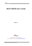
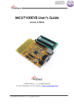
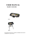
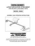
®
AIR COMPRESSOR PUMP
3 HORSEPOWER
Model 09592
ASSEMBLY AND
OPERATING INSTRUCTIONS
®
3491 Mission Oaks Blvd., Camarillo, CA 93011
Visit our Web site at http://www.harborfreight.com
Copyright 2003 by Harbor Freight Tools®. All rights reserved. No portion of this
manual or any artwork contained herein may be reproduced in any shape or form
without the express written consent of Harbor Freight Tools.
For technical questions, please call 1-800-444-3353.
PRODUCT SPECIFICATIONS
Item
Product Capability
Pump Stage
Maximum Pressure
Maximum Intake Capacity
Pump RPM
Cylinder Design
Stroke
Oil Capacity
Shaft Diameter
Mounting Holes
Description
For use with 3 HP, 3400 RPM (not included)
Single
140 PSI
8.05 CFM
1,200 RPM
Twin
1.57”
28.73 ounces
15/16”
Qty. 4 / 3/8” Diameter /
Bolt Pattern: 5-1/2” L x 7-1/2” W
Lubrication System Design
Construction
Pulley Design / Size
Splash
Aluminum Head, Pump, Flywheel / Cast Iron Sleeve
Belt Driven
10-5/8” Dia. X 1/2” Belt, CCW Rotation
23.25 Pounds
Weight
SAVE THIS MANUAL
You will need this manual for the safety warnings and precautions, assembly,
operating, inspection, maintenance and cleaning procedures, parts list and
assembly diagram. Keep your invoice with this manual. Write the invoice
number on the inside of the front cover. Keep this manual and invoice in a safe
and dry place for future reference.
GENERAL SAFETY WARNINGS AND PRECAUTIONS
1.
KEEP WORK AREA CLEAN AND DRY. Cluttered, damp, or wet work areas
invite injuries.
2.
KEEP CHILDREN AWAY FROM WORK AREA. Do not allow children to handle
this product.
3.
STORE IDLE EQUIPMENT. When not in use, tools and equipment should be
stored in a dry location to inhibit rust. Always lock up tools and equipment, and
keep out of reach of children.
4.
DO NOT USE THIS PRODUCT IF UNDER THE INFLUENCE OF ALCOHOL OR
DRUGS. Read warning labels on prescriptions to determine if your judgement or
reflexes are impaired while taking drugs. If there is any doubt, do not attempt to
use this product.
SKU 09592
PAGE 2
REV 04/04
5.
USE EYE AND HAND PROTECTION. Wear ANSI approved safety impact eye
goggles and heavy-duty work gloves when using this product. ANSI
approved safety impact eye goggles and heavy-duty work gloves are available
from Harbor Freight Tools.
6.
DRESS SAFELY. Do not wear loose clothing or jewelry, as they can become
caught in moving parts. Wear a protective hair covering to prevent long hair from
becoming caught in moving parts. If wearing a long-sleeve shirt, roll sleeves up
above elbows.
7.
DO NOT OVERREACH. Keep proper footing and balance at all times to prevent
tripping, falling, back injury, etcetera.
8.
INDUSTRIAL APPLICATIONS MUST FOLLOW OSHA REQUIREMENTS.
9.
STAY ALERT. Watch what you are doing at all times. Use common sense. Do
not use this product when you are tired or distracted from the job at hand.
10.
CHECK FOR DAMAGED PARTS. Before using this product, carefully check that
it will operate properly and perform its intended function. Check for damaged
parts and any other conditions that may affect the operation of this product. Replace or repair damaged or worn parts immediately.
11.
REPLACEMENT PARTS AND ACCESSORIES: When servicing, use only
identical replacement parts. Only use accessories intended for use with this
product. Approved accessories are available from Harbor Freight Tools.
12.
MAINTAIN THIS PRODUCT WITH CARE. Keep this product clean and dry for
better and safer performance.
13.
MAINTENANCE: For your safety, service and maintenance should be performed
regularly by a qualified technician.
14.
USE THE RIGHT TOOL FOR THE JOB. Do not attempt to force a small tool or
attachment to do the work of a larger industrial tool. There are certain
applications for which this tool was designed. It will do the job better and more
safely at the rate for which it was intended. Do not modify this tool, and do not
use this tool for a purpose for which it was not intended.
15.
WARNING: The warnings, precautions, and instructions discussed in this manual
cannot cover all possible conditions and situations that may occur. The operator
must understand that common sense and caution are factors, which cannot be
built into this product, but must be supplied by the operator.
SKU 09592
PAGE 3
SPECIFIC PRODUCT WARNINGS AND PRECAUTIONS
1.
THIS AIR COMPRESSOR PUMP IS DESIGNED FOR USE ONLY WITH A
3 HORSEPOWER MOTOR 3,400 RPM (not included).
2.
WARNING! Make sure to fill the Air Compressor Pump with a premium quality,
30-weight, non-detergent oil before each use. Running the Air Compressor
Pump with no oil or low oil will cause damage to the equipment.
3.
WHEN FILLING WITH OIL: Make sure to unscrew (do not pull) the Oil Fill Plug
(part #20) out. (See Figure D.)
4.
MAKE SURE ALL TOOLS AND EQUIPMENT USED WITH THE AIR
COMPRESSOR PUMP ARE RATED TO THE APPROPRIATE CAPACITY. Do
not use any tool or equipment that does not operate from 0 to 140 PSI.
5.
MAINTAIN A SAFE WORKING ENVIRONMENT. Keep the work area well lit.
Make sure there is adequate surrounding workspace. Always keep the work
area free of obstructions, grease, oil, trash, and other debris. Do not use the Air
Compressor Pump in areas near flammable chemicals, dusts, and vapors.
6.
AVOID INJURY: Never direct the Exhaust Elbow (part #3) at people or animals.
(See Figure D.)
7.
AVOID BURNS: The Air Compressor Pump becomes very hot during use and for
a while after its use. Do not touch the Air Compressor Pump until it has completely cooled.
8.
WARNING! DO NOT USE THE AIR COMPRESSOR PUMP UNTIL A PROPERLY FUNCTIONING PULLEY/BELT GUARD (not included) HAS BEEN
INSTALLED. (See Figure C.)
9.
BEFORE PERFORMING ANY INSPECTION, MAINTENANCE, OR CLEANING
PROCEDURES, MAKE SURE ALL AIR PRESSURE HAS BEEN RELEASED
FROM THE AIR COMPRESSOR’S TANK (not included) AND THAT THE
EQUIPMENT IS UNPLUGGED FROM ITS ELECTRICAL OUTLET, and ALL
COMPONENTS HVAE COLLED.
WARNING! This product contains or produces a chemical known to the State of
California to cause cancer and birth defects (or other reproductive harm).
(California Health & Safety Code 25249.5 et seq.)
10.
SKU 09592
PAGE 4
UNPACKING
When unpacking, check to make sure all the parts shown on the Parts List on page 9 are
included. If any parts are missing or broken, please call Harbor Freight Tools at the number shown on the cover of this manual as soon as possible.
ASSEMBLY INSTRUCTIONS
NOTE: For additional references to the parts mentioned in the following pages, refer to
the Assembly Diagram on page 10.
To Attach The Air Compressor Pump To A Mounting Surface:
1.
NOTE: Depending on your level of assembly expertise, you may wish to have a
qualified technician perform the assembly procedures.
2.
CAUTION: Make sure the mounting surface (air compressor stand, workbench, etc.) to which the Air Compressor Pump will be attached is flat, level, and
sturdy enough to withstand the weight of the Air Compressor Pump and all other
necessary equipment and accessories.
3.
At the base of the Air Compressor Pump are four 3/8” mounting holes with a hole
pattern of 5-1/2” long by 7-1/2” wide. If four 3/8” mounting holes with a hole
pattern of 5-1/2” long by 7-1/2” wide do not already exist in the mounting surface,
it will be necessary to drill the four 3/8” mounting holes through the mounting
surface. IMPORTANT: Prior to drilling, make sure there are no electrical cables,
wires or other obstructions in the drilling path. (See Figure A.)
4.
To do so, temporarily position the Air Compressor Pump in the desired location
on the mounting surface. Use the base of the Air Compressor Pump, with its four
3/8” mounting holes, as a template by which to mark the four 3/8” mounting holes
that are to be drilled through the mounting surface. Then, remove the Air Compressor Pump from the mounting surface. NOTE: You may also follow the illustration below by which to measure where each of the four 3/8” mounting holes
should be drilled. (See Figure A.)
5-1/2”
7-1/2”
BOTTOM VIEW
PULLEY
(#38)
BASE OF AIR COMPRESSOR PUMP
FIGURE A
SKU 09592
PAGE 5
5.
Once the four 3/8” mounting holes are drilled through the mounting surface,
place the Air Compressor Pump on the mounting surface and align its four
mounting holes with the four drilled mounting holes on the mounting surface.
Then, secure the Air Compressor Pump to the mounting surface, using four 3/8”
Bolts of appropriate length, four Lockwashers, and four Nuts (all not included).
6.
The Air Compressor Pump requires the use of a “V” Pulley Belt (not included).
The “V” Pulley Belt should be no wider than 1-5/16” wide at its widest point and
of appropriate length depending on the distance between the Air Compressor
Pump’s Pulley (part #38) and the 3 HP Motor’s Pulley (not included). Once the
“V” Belt Pulley is installed, its proper length is indicated by pushing down with
your finger midway on the “V” Belt Pulley. The “V” Belt Pulley should not depress more than 1/2”. (See Figure B.)
“V” BELT PULLEY
(NOT INCLUDED)
3 HP MOTOR PULLEY
(NOT INCLUDED)
PULLEY
(#38)
FIGURE B
7.
WARNING! To avoid personal injury and/or property damage, it is recommended
that a properly functioning Pulley/Belt Guard (not included) be installed. The
Pulley/Belt Guard should fully enclose (front, back, top, bottom) the Air Compressor Pump’s Pulley (part #38), the “V” Belt, and the Motor’s Pulley. NOTE: Make
sure to allow for about 1” clearance, on all sides, between the Pulley/Belt Guard
and the Air Compressor Pump’s Pulley, the “V” Belt, and the Motor’s Pulley.
(See Figure C.)
CONVENTIONAL PULLEY/BELT GUARD
(NOT INCLUDED)
FIGURE C
SKU 09592
PAGE 6
8.
Attach the Air Compressor Tank’s Inlet Hose (not included) to the 1/2” by 14-TPI
Exhaust Elbow (part #3). NOTE: Make sure to wrap the male threads of Tank’s
Inlet Hose Connector with pipe seal tape (not included). Then, screw the Connector firmly into the Exhaust Elbow. (See Figure D.)
EXHAUST ELBOW
(#3)
ATTACH
AIR TANK INLET HOSE
(NOT INCLUDED)
HERE.
AIR FILTER
(#4)
OIL FILL PLUG
(#20)
OIL WINDOW
(#25)
FIGURE D
OPERATING INSTRUCTIONS
NOTE: For additional references to the parts mentioned in the following pages, refer to
the Assembly Diagram on page 10.
To Check The Oil Level:
1.
The Oil Window (part #25) is used to determine if oil is needed. To check the oil,
observe the Oil Window. The oil should appear at the midway point (horizontally) in the circle of the Oil Window. (See Figure D.)
Note: The optimal capacity of the oil tank is 28.73 ounces.
2.
If the oil level is below the midway point in the Oil Window (part #25) then it is
necessary to add a premium quality, 30-weight, non-detergent oil until the level of
oil reaches the midway point in the Oil Window. Do not overfill. NOTE: Make
sure to unscrew the Oil Fill Plug and remove it from its Oil Fill Hole. Add the
new oil. Then screw the Oil Fill Plug back into the Oil Fill Hole, being careful not
to strip the threads. (See Figure D.)
SKU 09592
PAGE 7
REV 02/04
3.
Start the Air Compressor, and visually check the “V” Belt for proper tension. Also
check for air leaks in the system, abnormal noise or vibration. If a problem occurs immediately disconnect the Air Compressor from its electrical supply source,
release all air pressure from the system, and have the problem corrected before
further use.
4.
IMPORTANT: After starting the Air Compressor Pump, it should run for about 30
minutes without a load in order for it to build up sufficient air pressure.
INSPECTION, MAINTENANCE, AND CLEANING
1.
WARNING! Before performing any inspection, maintenance, and cleaning procedures, make sure all air pressure has been released from the Air Compressor’s
Tank and that the Air Compressor is unplugged from its electrical outlet.
2.
BEFORE EACH USE, inspect the general condition of the Air Compressor
Pump. Check all air fittings for leaks. Check for loose screws, misalignment or
binding of moving parts, cracked or broken parts, and any other condition that
may affect the safe operation of this equipment. If abnormal noise or vibration
occurs, immediately disconnect the Air Compressor from its electrical supply
source and have the problem corrected before further use.
Do not use damaged equipment.
3.
DAILY: Check the Air Compressor Pump’s oil level. If necessary, fill with a premium quality, 30-weight, non-detergent oil. NOTE: When checking the oil level,
make sure to unscrew (do not pull) the Oil Fill Plug (part #20).
(See Figure D.)
4.
EVERY 100 HOURS OF USE: Clean the Air Filter Element (part #4) with a mild
solvent. Then, dry and re-attach the Air Filter Element. NOTE: Replace the Air
Filter Element if it is too dirty to properly clean. (See Assy. Diagram.)
5.
EVERY 500 HOURS OR 12 MONTHS: Replace the old oil with new, premium
quality, 30-weight, non-detergent oil.
6.
TO CLEAN: wipe with a damp cloth, using a mild detergent or mild solvent.
7.
WHEN STORING: Keep the Air Compressor Pump in a clean, dry location.
SKU 09592
PAGE 8
PLEASE READ THE FOLLOWING CAREFULLY
THE MANUFACTURER AND/OR DISTRIBUTOR HAS PROVIDED THE PARTS LIST AND ASSEMBLY
DIAGRAM IN THIS MANUAL AS A REFERENCE TOOL ONLY. NEITHER THE MANUFACTURER OR
DISTRIBUTOR MAKES ANY REPRESENTATION OR WARRANTY OF ANY KIND TO THE BUYER THAT
HE OR SHE IS QUALIFIED TO MAKE ANY REPAIRS TO THE PRODUCT, OR THAT HE OR SHE IS
QUALIFIED TO REPLACE ANY PARTS OF THE PRODUCT. IN FACT, THE MANUFACTUER AND/OR
DISTRIBUTOR EXPRESSLY STATES THAT ALL REPAIRS AND PARTS REPLACEMENTS SHOULD BE
UNDERTAKEN BY CERTIFIED AND LICENSED TECHNICIANS, AND NOT BY THE BUYER. THE BUYER
ASSUMES ALL RISK AND LIABILITY ARISING OUT OF HIS OR HER REPAIRS TO THE ORIGINAL
PRODUCT OR REPLACEMENT PARTS THERETO, OR ARISING OUT OF HIS OR HER INSTALLATION
OF REPLACEMENT PARTS THERETO.
PARTS LIST
Part #
1
2
3
4
5
6
7
8
9
10
11
12
13
14
15
16
17
18
19
20
Description
Screw
Cylinder Head
Exhaust Elbow
Air Filter
Spring Washer
Screw
Cylinder Head Washer
Valve Plate Seat
Valve Plate
Aluminum Washer
Cylinder Up Washer
Piston Ring Assembly
Piston
Piston Pin
Retaining Ring In Hole
Connect Rod Assembly
Bolt
Cylinder
Cylinder Down Washer
Oil Fill Plug
Qty.
6
1
1
1
2
2
1
2
4
1
2
2
2
2
4
2
6
1
1
1
Part #
21
22
23
24
25
26
27
28
29
30
31
32
33
34
35
36
37
38
39
40
Description
Bolt
Crankcase Front Cover
Crankcase Front Washer
O-Ring
Oil Window
Oil Drain Plug
O-Ring
Crankcase Seal
Crankcase Down Cover
Bolt
Crankcase
Bearing
Crankshaft
Crankcase Back Washer
Oil Seal
Crankcase Back Cover
Bolt
Pulley
Large Washer
Bolt
Qty.
3
1
1
1
1
1
1
1
1
8
1
2
1
1
1
1
3
1
1
1
NOTE: Some parts are listed and shown for illustration purposes only, and are not
available individually as replacement parts.
SKU 09592
PAGE 9
ASSEMBLY DIAGRAM
1
6
5
4
2
3
7
8
9
10
8
11
12
14
15
16
13
37
40
20
39
17
18
19
35
32
32
20
22
36
38
34
33
23
31
21
24
25
28
27
26
29
30
NOTE: Some parts are listed and shown for illustration purposes only, and are not
available individually as replacement parts.
SKU 09592
PAGE 10