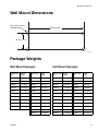
1
Instructions - Parts List
Merkur™ Spray
Packages
309463N
Important Safety Instructions
Read all warnings and instructions in this manual.
Save these instructions.
TI2101A
TI2102A
TI2103A
II 2 G
Contents
Manual Conventions . . . . . . . . . . . . . . . . . . . . . . 2
Related Manuals . . . . . . . . . . . . . . . . . . . . . . . . . 2
Model Information . . . . . . . . . . . . . . . . . . . . . . . . . . 3
Wall Mount Sprayers . . . . . . . . . . . . . . . . . . . . . . 3
Cart Mount Sprayers . . . . . . . . . . . . . . . . . . . . . . 4
Warning . . . . . . . . . . . . . . . . . . . . . . . . . . . . . . . . . . . 5
Installation . . . . . . . . . . . . . . . . . . . . . . . . . . . . . . . . 8
General Information . . . . . . . . . . . . . . . . . . . . . . 8
Grounding . . . . . . . . . . . . . . . . . . . . . . . . . . . . . . 8
Install the Muffler . . . . . . . . . . . . . . . . . . . . . . . . . 8
Air and Fluid Hoses . . . . . . . . . . . . . . . . . . . . . . . 8
Wall Mount Packages . . . . . . . . . . . . . . . . . . . . 10
Air Inlet Fitting . . . . . . . . . . . . . . . . . . . . . . . . . . 10
Air Line Accessories . . . . . . . . . . . . . . . . . . . . . 10
Fluid Inlet Fitting . . . . . . . . . . . . . . . . . . . . . . . . 10
Suction Tube Strainer . . . . . . . . . . . . . . . . . . . . 10
Fluid Line Accessories . . . . . . . . . . . . . . . . . . . 10
Flush the Pump Before First Use . . . . . . . . . . . 10
Installing a Fluid Regulator (accessory) . . . . . . 11
Operation . . . . . . . . . . . . . . . . . . . . . . . . . . . . . . . . 12
Pressure Relief Procedure . . . . . . . . . . . . . . . . 12
Starting and Adjusting the Pump . . . . . . . . . . . 13
Shutdown and Care of the Pump . . . . . . . . . . . 13
Flush the Equipment . . . . . . . . . . . . . . . . . . . . . 14
Maintenance . . . . . . . . . . . . . . . . . . . . . . . . . . . . . . 15
Preventive Maintenance Schedule . . . . . . . . . . 15
Storage . . . . . . . . . . . . . . . . . . . . . . . . . . . . . . . 15
Tightening Threaded Connections . . . . . . . . . . 15
Cleaning . . . . . . . . . . . . . . . . . . . . . . . . . . . . . . 15
Wet-Cup . . . . . . . . . . . . . . . . . . . . . . . . . . . . . . 15
Troubleshooting . . . . . . . . . . . . . . . . . . . . . . . . . . . 16
Parts . . . . . . . . . . . . . . . . . . . . . . . . . . . . . . . . . . . . 18
Wall Mount Packages . . . . . . . . . . . . . . . . . . . . 18
Cart Mount Packages . . . . . . . . . . . . . . . . . . . . 20
Air Inlet Details . . . . . . . . . . . . . . . . . . . . . . . . . 22
Hose and Gun Details . . . . . . . . . . . . . . . . . . . . 24
Technical Data . . . . . . . . . . . . . . . . . . . . . . . . . . . . 26
Wall Mount Dimensions . . . . . . . . . . . . . . . . . . . . 27
Package Weights . . . . . . . . . . . . . . . . . . . . . . . . . . 27
Wall Mount Sprayers . . . . . . . . . . . . . . . . . . . . . 27
Cart Mount Sprayers . . . . . . . . . . . . . . . . . . . . . 27
Graco Standard Warranty . . . . . . . . . . . . . . . . . . . 28
Graco Information . . . . . . . . . . . . . . . . . . . . . . . . . 28
2
Manual Conventions
Warning
WARNING
A warning alerts you to the possibility of serious injury
or death if you do not follow the instructions.
Symbols, such as fire and explosion (shown above),
alert you to a specific hazard and direct you to read
the indicated hazard warnings (pages 5-6) for detailed
information.
Caution
CAUTION
A caution alerts you to the possibility of damage to or
destruction of equipment if you do not follow the
instructions.
Note
A note calls attention to additional helpful information.
Related Manuals
AA Series Spray Gun Manual 311001
Merkur Pump Manual 309462
Fluid Filter Manual 307273
309463N
Model Information
Model Information
Wall Mount Sprayers
Sprayer Includes:
Sprayer
Part No.
Series
Ratio
Pump
Model
Thread
Type
Bare
Sprayer
Air
Siphon Fluid
Controls Hose
Filter
Maximum Fluid
Maximum Air
Working
Input Pressure
Hose
Pressure
and Gun psi (MPa, bar) psi (MPa, bar)
233891* A
15:1
015.050 BSPP
✔
100 (0.7, 7)
1500 (10.5, 105)
233892* A
20:1
020.035 BSPP
✔
100 (0.7, 7)
2000 (14.0, 140)
233893* A
30:1
030.020 BSPP
✔
100 (0.7, 7)
3000 (21.0, 210)
233894* A
30:1
030.050 BSPP
✔
100 (0.7, 7)
3000 (21.0, 210)
233895* A
40:1
040.035 BSPP
✔
100 (0.7, 7)
4000 (28.0, 280)
233896
A
15:1
015.050 NPT
✔
100 (0.7, 7)
1500 (10.5, 105)
233897
A
20:1
020.035 NPT
✔
100 (0.7, 7)
2000 (14.0, 140)
233898
A
30:1
030.020 NPT
✔
100 (0.7, 7)
3000 (21.0, 210)
233899
A
30:1
030.050 NPT
✔
100 (0.7, 7)
3000 (21.0, 210)
233900
A
40:1
040.035 NPT
✔
100 (0.7, 7)
4000 (28.0, 280)
233901
A
15:1
015.050 NPT
✔
✔
✔
100 (0.7, 7)
1500 (10.5, 105)
233902
A
20:1
020.035 NPT
✔
✔
✔
100 (0.7, 7)
2000 (14.0, 140)
233903
A
30:1
030.020 NPT
✔
✔
✔
100 (0.7, 7)
3000 (21.0, 210)
233904
B
30:1
030.050 NPT
✔
✔
✔
100 (0.7, 7)
3000 (21.0, 210)
233905
A
40:1
040.035 NPT
✔
✔
✔
100 (0.7, 7)
4000 (28.0, 280)
233906
B
15:1
015.050 NPT
✔
✔
✔
✔
✔ (AA)
100 (0.7, 7)
1500 (10.5, 105)
233907
B
20:1
020.035 NPT
✔
✔
✔
✔
✔ (AA)
100 (0.7, 7)
2000 (14.0, 140)
233908
B
30:1
030.020 NPT
✔
✔
✔
✔
✔ (AA)
100 (0.7, 7)
3000 (21.0, 210)
233909
B
30:1
030.050 NPT
✔
✔
✔
✔
✔ (AA)
100 (0.7, 7)
3000 (21.0, 210)
233910
B
40:1
040.035 NPT
✔
✔
✔
✔
✔ (AA)
100 (0.7, 7)
4000 (28.0, 280)
288120
A
15:1
015.050 NPT
✔
✔
✔
✔
✔ (AA
Carbide)
100 (0.7, 7)
1500 (10.5, 105)
*
These packages are only available in Europe.
(AA) These packages are Air Assisted Spray packages.
309463N
3
Model Information
Cart Mount Sprayers
Sprayer Includes:
Sprayer
Part No.
Series
Ratio
Pump
Model
Thread
Type
Air
Siphon
Controls Cup
Siphon
Hose
Fluid
Filter
Maximum Air Maximum Fluid
Input Pressure Working Pressure
Hose and
psi (MPa, bar) psi (MPa, bar)
Gun
233911* A
15:1
015.050
NPT
✔
✔
100 (0.7, 7)
1500 (10.5, 105)
233912* A
20:1
020.035
NPT
✔
✔
100 (0.7, 7)
2000 (14.0, 140)
233913* A
30:1
030.020
NPT
✔
✔
100 (0.7, 7)
3000 (21.0, 210)
233914* A
30:1
030.050
NPT
✔
✔
100 (0.7, 7)
3000 (21.0, 210)
233915* A
40:1
040.035
NPT
✔
✔
100 (0.7, 7)
4000 (28.0, 280)
233916* B
15:1
015.050
NPT
✔
✔
✔
✔ (AA)
100 (0.7, 7)
1500 (10.5, 105)
233917* B
20:1
020.035
NPT
✔
✔
✔
✔ (AA)
100 (0.7, 7)
2000 (14.0, 140)
233918* B
30:1
030.020
NPT
✔
✔
✔
✔ (AA)
100 (0.7, 7)
3000 (21.0, 210)
233919* B
30:1
030.050
NPT
✔
✔
✔
✔ (AA)
100 (0.7, 7)
3000 (21.0, 210)
233920* B
40:1
040.035
NPT
✔
✔
✔
✔ (AA)
100 (0.7, 7)
4000 (28.0, 280)
233921
A
15:1
015.050
NPT
✔
✔
100 (0.7, 7)
1500 (10.5, 105)
233922
A
20:1
020.035
NPT
✔
✔
100 (0.7, 7)
2000 (14.0, 140)
233923
A
30:1
030.020
NPT
✔
✔
100 (0.7, 7)
3000 (21.0, 210)
233924
A
30:1
030.050
NPT
✔
✔
100 (0.7, 7)
3000 (21.0, 210)
233925
A
40:1
040.035
NPT
✔
✔
100 (0.7, 7)
4000 (28.0, 280)
233926
B
15:1
015.050
NPT
✔
✔
✔
✔ (AA)
100 (0.7, 7)
1500 (10.5, 105)
233927
B
20:1
020.035
NPT
✔
✔
✔
✔ (AA)
100 (0.7, 7)
2000 (14.0, 140)
233928
B
30:1
030.020
NPT
✔
✔
✔
✔ (AA)
100 (0.7, 7)
3000 (21.0, 210)
233929
B
30:1
030.050
NPT
✔
✔
✔
✔ (AA)
100 (0.7, 7)
3000 (21.0, 210)
233930
B
40:1
040.035
NPT
✔
✔
✔
✔ (AA)
100 (0.7, 7)
4000 (28.0, 280)
234725
A
30:1
030.050
NPT
✔
✔
100 (0.7, 7)
3000 (21.0, 210)
234726
A
40:1
040.035
NPT
✔
✔
100 (0.7, 7)
4000 (28.0, 280)
234727
A
30:1
030.050
NPT
✔
✔
✔
✔(A)
100 (0.7, 7)
3000 (21.0, 210)
234728
A
40:1
040.035
NPT
✔
✔
✔
✔(A)
100 (0.7, 7)
4000 (28.0, 280)
288123
A
15:1
015.050
NPT
✔
✔
✔
✔ (AA
Carbide)
100 (0.7, 7)
1500 (10.5, 105)
*These packages are only available in Europe.
(A) Airless Spray packages.
(AA) Air Assisted Spray packages.
4
309463N
Warning
WARNING
EQUIPMENT MISUSE HAZARD
Equipment misuse can cause the equipment to rupture or malfunction and result in serious injury.
•
This equipment is for professional use only.
•
Read all instruction manuals, tags, and labels before operating the equipment.
•
Use the equipment only for its intended purpose. If you are not sure, call your Graco distributor.
•
Do not alter or modify this equipment. Use only genuine Graco parts and accessories.
•
Check equipment daily. Repair or replace worn or damaged parts immediately.
•
Do not exceed the maximum working pressure of the lowest rated system component. Refer to the
Technical Data on page 26 for the maximum working pressure of this equipment.
•
Use fluids and solvents which are compatible with the equipment wetted parts. Refer to the Technical Data section of all equipment manuals. Read the fluid and solvent manufacturer's warnings.
•
Do not use hoses to pull equipment.
•
Route hoses away from traffic areas, sharp edges, moving parts, and hot surfaces. Do not expose
Graco hoses to temperatures above 82°C (180°F) or below -40°C (-40°F).
•
Wear hearing protection when operating this equipment.
•
Comply with all applicable local, state, and national fire, electrical, and safety regulations.
SKIN INJECTION HAZARD
Spray from the gun, leaks or ruptured components can inject fluid into your body and cause extremely
serious injury, including the need for amputation. Fluid splashed in the eyes or on the skin can also
cause serious injury.
309463N
•
Fluid injected into the skin might look like just a cut, but it is a serious injury. Get immediate surgical
treatment.
•
Do not point the gun at anyone or at any part of the body.
•
Do not put your hand or fingers over the spray tip.
•
Do not stop or deflect leaks with your hand, body, glove or rag.
•
Do not "blow back” fluid; this is not an air spray system.
•
Always have the tip guard and the trigger guard on the gun when spraying.
•
Check the gun diffuser operation weekly. Refer to the gun manual.
•
Be sure the gun trigger safety operates before spraying.
•
Lock the gun trigger safety when you stop spraying.
•
Follow the Pressure Relief Procedure on page 12 if the spray tip clogs and before cleaning, checking or servicing the equipment.
•
Tighten all fluid connections before operating the equipment.
•
Check the hoses, tubes, and couplings daily. Replace worn or damaged parts immediately.
•
Do not repair high pressure couplings; you must replace the entire hose.
5
Warning
WARNING
FIRE AND EXPLOSION HAZARD
Improper grounding, poor ventilation, open flames or sparks can cause a hazardous condition and result
in a fire or explosion and serious injury.
•
Ground the equipment and the object being sprayed. Refer to Grounding on page 8.
•
If there is any static sparking or you feel an electric shock while using this equipment, stop spraying
immediately. Do not use the equipment until you identify and correct the problem.
•
Provide fresh air ventilation to avoid the buildup of flammable fumes from solvents or the fluid being
sprayed.
•
Keep the spray area free of debris, including solvent, rags, and gasoline.
•
Electrically disconnect all equipment in the spray area.
•
Extinguish all open flames or pilot lights in the spray area.
•
Do not smoke in the spray area.
•
Do not turn on or off any light switch in the spray area while operating or if fumes are present.
•
Do not operate a gasoline engine in the spray area.
TOXIC FLUID HAZARD
Hazardous fluid or toxic fumes can cause serious injury or death if splashed in the eyes or on the skin,
inhaled, or swallowed.
6
•
Know the specific hazards of the fluid you are using.
•
Store hazardous fluid in an approved container. Dispose of hazardous fluid according to all local,
state and national guidelines.
•
Always wear protective eyewear, gloves, clothing and respirator as recommended by the fluid and
solvent manufacturer.
309463N
Warning
309463N
7
Installation
Installation
General Information
2. Air and fluid hoses: use only electrically conductive
hoses.
3. Air compressor: follow manufacturer's recommendations.
•
Reference numbers and letters in parentheses
in the text refer to the callouts in the figures
and the parts drawing.
•
Always use Genuine Graco Parts and Accessories, available from your Graco distributor. If
you supply your own accessories, be sure they
are adequately sized and pressure-rated for
your system.
5. Fluid supply container: follow your local code.
FIG. 2 is a guide for selecting and installing
system components and accessories. It is not
an actual system design. Contact your Graco
distributor for assistance in designing a system
to suit your particular needs.
7. Solvent pails used when flushing: follow your local
code. Use only metal pails, which are conductive,
placed on a grounded surface. Do not place the pail
on a nonconductive surface, such as paper or cardboard, which interrupts the grounding continuity.
•
4. Spray gun: ground through connection to a properly
grounded fluid hose and pump.
6. Object being sprayed: follow your local code.
Grounding
WARNING
TI1102
Before operating the pump, ground the system as
explained below. Read the warnings on page 6.
1. Pump: use Part No. 238909 Ground Wire and
Clamp (supplied). See FIG. 1. Insert one end of the
ground wire (Y) into the pump’s grounding clamp (X)
and tighten the screw (W) securely. Connect the
other end of the wire to a true earth ground.
TI1102
8. To maintain grounding continuity when flushing or
relieving pressure, hold a metal part of the spray
gun firmly to the side of a grounded metal pail, then
trigger the gun.
Install the Muffler
The muffler (C, FIG. 2) is shipped loose. Screw the muffler into the muffler port before installing the pump.
Air and Fluid Hoses
Y
See FIG. 2. Be sure all air hoses (A, P) and fluid hoses
(R, U) are properly sized and pressure-rated for your
system. Use only electrically conductive hoses. Fluid
hoses must have spring guards on both ends. Use a
swivel (S) between the fluid hose (R) and the gun (T) to
allow easier gun movement.
X
W
ti1930a
FIG. 1. Grounding Wire
8
309463N
Installation
M
L
A
D
T
N
C
P
Y
S
B
H
U
E
F
K
G
J
G
R
TI1763C
FIG. 2. Typical Installation
Key:
A Pump Air Supply Line
B Bleed-Type Master Air Valve
C Muffler
D Pump Air Pressure Regulator
E Pump
F Fluid Filter
G Fluid Drain Valve
H Fluid Shutoff Valve
J Fluid Pressure Regulator
K Fluid Suction Tube
L Air Shutoff Valve
309463N
M
N
P
R
S
T
U
Y
Air Line Filter
Gun Air Pressure Regulator
Gun Air Supply Line
Gun Fluid Supply Line
Gun Swivel
Air-Assisted Spray Gun
Fluid Whip Hose
Pump Ground Wire
9
Installation
Wall Mount Packages
Fluid Inlet Fitting
FIG. 2 illustrates a wall mount system.
The packages include either a fluid inlet adapter (7) or
an elbow (8). These fittings include a sealing o-ring (7a,
8a). Be sure the o-ring is in place before installing the fitting. Screw the fitting into the pump a minimum of two
full turns, until it faces the desired direction. It is not necessary to fully engage the threads. Do not overtighten.
1. Be sure the wall can support the weight of the
pump, bracket, hoses and accessories, as well as
the stress caused during operation.
2. Position the wall bracket (4) about 1.2-1.5 m (4-5 ft)
above the floor. For ease of operation and service,
make sure the pump air inlet, fluid inlet, and fluid
outlet ports are easily accessible.
If your package uses the fluid inlet elbow (8), connect
the suction tube by pushing the tube into the elbow until
it seats, then tighten the elbow nut to secure the tube.
3. Using the wall bracket (4) as a template, drill 9 mm
mounting holes in the wall. Wall mounting dimensions are shown on page 27.
Suction Tube Strainer
4. Attach the bracket to the wall. Use screws that are
long enough to keep the pump from vibrating during
operation. Be sure the bracket is level.
To replace the suction tube stainer (9a), loosen the
clamp and remove the strainer. Slide the new clamp
onto the suction tube, install the new strainer, then slide
the clamp onto the strainer and squeeze it to tighten.
Air Inlet Fitting
Fluid Line Accessories
The air inlet fitting (104) is held in place with a setscrew.
See page 22. Loosen this setscrew before removing the
fitting. Tighten the setscrew to hold the fitting in place.
Install the following accessories in the positions shown
in FIG. 2, using adapters as necessary:
•
A fluid filter (F) with a 60 mesh (250 micron) stainless steel element, to filter particles from the fluid as
it leaves the pump. Install a fluid drain valve (G),
which is required in your system to relieve fluid pressure in the hose and gun.
•
A fluid shutoff valve (H) shuts off fluid flow.
•
A fluid pressure regulator (J) allows more precise
adjustment of the fluid pressure. See page 11.
•
A gun or valve (T) dispenses the fluid. The gun
shown in FIG. 2 is an air-assisted spray gun for light
to medium viscosity fluids.
•
A fluid line swivel (S) allows easier gun movement.
•
A suction kit (K) allows the pump to draw fluid from a
fluid container.
Air Line Accessories
Install the following accessories in the order shown in
FIG. 2, using adapters as necessary:
•
A bleed-type master air valve (B) is required in your
system to relieve air trapped between it and the air
motor when the valve is closed. Be sure the bleed
valve is easily accessible from the pump.
•
A pump air regulator (D) controls pump speed and
outlet pressure by adjusting the air pressure to the
pump. Locate the regulator close to the pump.
•
A gun air regulator (N) controls air pressure to the
air-assisted spray gun.
•
An air line filter (M) removes harmful dirt and moisture from the compressed air supply.
•
A second bleed-type air valve (L) isolates the air line
accessories for servicing. Locate upstream from all
other air line accessories.
10
Flush the Pump Before First Use
The pump is tested with lightweight oil, which is left in to
protect the pump parts. If the fluid you are using may be
contaminated by the oil, flush it out with a compatible
solvent before using the pump. See Flush the Equipment on page 14.
309463N
Installation
Installing a Fluid Regulator
(accessory)
Packages With a Fluid Filter
Packages Without a Fluid Filter
2. Install Part No. 235208 3/8 npt (mxf) Swivel (B) in
the inlet of Fluid Filter 223160 (F). The swivel and filter are supplied with some packages.
1. Install Kit 234083 (nipple and washer) into pump
fluid outlet.
2. Install Part No. 112497 1/4 npt(m) x 3/8 npsm(f)
Swivel (B) in the inlet of Fluid Regulator 222121 (J).
See manual 307886 for information on the fluid regulator.
3. Install Part No. 166846 1/4 npt x 1/4 npsm Nipple
(C) in the outlet of Fluid Regulator 222121 (J).
4. Screw the swivel (B) onto the nipple (A).
1. Install Kit 234083 (nipple and washer) into pump
fluid outlet.
3. Install Part No. 166846 1/4 npt x 1/4 npsm Nipple
(C) in the outlet of Fluid Regulator 222121 (J). See
manual 307886 for information on the fluid regulator.
4. Screw the fluid regulator (J) onto the nipple (D) at
the outlet of the fluid filter (F).
5. Screw the swivel (B) onto the nipple (A).
6. Connect the fluid hose to nipple (C).
5. Connect the fluid hose to nipple (C).
F
B
B
A
TI2104A
A
TI2104A
C
J
FIG. 3. Fluid Regulator on Package Without Fluid
Filter
309463N
C
J
D
FIG. 4. Fluid Regulator on Package With Fluid Filter
11
Operation
Operation
Pressure Relief Procedure
4. Trigger the gun into a grounded metal waste container to relieve the fluid pressure.
WARNING
Read the warnings on page 5, and follow the Pressure
Relief Procedure below whenever you:
•
are instructed to relieve pressure
•
stop spraying
•
check or service any of the equipment
•
install or clean the spray tip.
5. Lock the trigger.
1. Lock the trigger.
LOCK
6. Open the drain valve on the fluid filter and all other
fluid drain valves in the system, having a waste container ready to catch the drainage. Leave the drain
valve(s) open until you are ready to spray again.
LOCK
2. Turn off the air bleed valves to the fluid source and
to the gun.
OPEN
7. If the nozzle or hose is completely clogged or pressure is not fully relieved, slowly loosen the hose end
coupling. Now clear the nozzle or hose.
3. Unlock the trigger.
ti1298a
UNLOCK
12
309463N
Operation
Starting and Adjusting the Pump
1. Connect the suction kit (K) to the pump's fluid inlet,
and place the tube into the fluid supply.
8. If the pump fails to prime properly, open the drain
valve (G). Use the drain valve as a priming valve
until fluid flows from the valve. Close the drain valve
when all air is eliminated.
2. Close the pump air regulator (D).
OPEN
3. Open the pump's bleed-type master air valve (B).
4. Hold a metal part of the gun (T) firmly to the side of
a grounded metal pail and hold the trigger open.
CLOSED
9. With the pump and lines primed, and with adequate
air pressure and volume supplied, the pump will
start and stop as you open and close the gun. In a
circulating system, the pump will speed up or slow
down on demand, until the air supply is shut off.
10. Use the air regulator to control the pump speed and
the fluid pressure. Always use the lowest air pressure necessary to get the desired results. Higher
pressures cause premature tip and pump wear.
CAUTION
5. Slowly open the air regulator (D) until the pump
starts.
Never allow the pump to run dry of the fluid being
pumped. A dry pump will quickly accelerate to a high
speed, possibly damaging itself. If your pump accelerates quickly, or is running too fast, stop it immediately
and check the fluid supply. If the supply container is
empty and air has been pumped into the lines, refill
the container and prime the pump and the lines with
fluid, or flush and leave it filled with a compatible solvent. Be sure to eliminate all air from the fluid system.
Shutdown and Care of the Pump
6. Cycle the pump slowly until all air is pushed out and
the pump and hoses are fully primed.
7. Release the gun trigger and lock the trigger safety
latch. The pump should stall against pressure.
For a brief shutdown, relieve the pressure, page 12.
Stop the pump at the bottom of its stroke to prevent fluid
from drying on the exposed displacement rod and damaging the throat packings.
For a longer shutdown, or overnight, always flush the
pump before the fluid dries on the displacement rod,
page 14. Relieve the pressure, page 12.
LOCK
309463N
13
Operation
Flush the Equipment
3. Change the fluid source to solvent.
Flush before changing colors, at the end of the day,
before storing, and before repairing the equipment.
FLUSH
WARNING
Before flushing, be sure the entire system and all
grounding pails are properly grounded. See page 8.
Flush with a fluid that is compatible with the fluid you are
pumping and with the wetted parts of your system.
Check with your fluid manufacturer or supplier for recommended flushing fluids and flushing frequency.
Always flush the pump before fluid dries on the displacement rod.
1. Relieve the pressure, page 12.
4. Hold a metal part of the gun firmly to the side of a
grounded metal pail.
5. Start the pump. Always use the lowest possible fluid
pressure when flushing.
6. Trigger the gun. Flush until clean solvent flows from
the gun.
7. Relieve the pressure, page 12.
2. Remove the spray tip from the gun. See the gun
manual.
14
309463N
Maintenance
Maintenance
Preventive Maintenance
Schedule
Establish a preventive maintenance schedule, based on
the sprayer's service history.
Storage
Before storing the sprayer, always flush it, page 14.
Relieve pressure, page 12.
Cleaning
Clean the outside of the equipment daily, using a soft
cloth and compatible solvent.
Clean the suction tube (K) and inlet strainer daily, using
a compatible solvent.
Clean the air filter (M) in your main air line at least once
a week.
Wet-Cup
Tightening Threaded
Connections
Before each use, check all hoses for wear or damage.
Replace as necessary. Check that all threaded connections are tight and leak-free.
309463N
See FIG. 5. The level display is an indicator of the fluid
level in the wet-cup. Keep the level display 1/2 full of
Graco Throat Seal Liquid (TSL) or another compatible
fluid.
Periodically drain the wet-cup by removing the plug on
the opposite side from the level display, then refill with
TSL.
15
Troubleshooting
Troubleshooting
1. Relieve the pressure, page 12, before checking or
servicing the equipment.
Problem
Pump fails to operate.
Pump operates, but output is low on
both strokes.
Pump operates, but output is low on
downstroke.
Pump operates, but output is low on
upstroke.
Erratic or accelerated pump speed.
Fluid being pumped is visible in the
level display.
2. Check all possible problems and causes before disassembling the pump.
Cause
Solution
Restricted line or inadequate air supply; closed or clogged valves.
Obstructed fluid hose or gun; fluid
hose ID is too small.
Fluid dried on the displacement rod.
Clear line or increase air supply.
Check that valves are open.
Open, clear*; use hose with larger ID.
Clean; always stop pump at the bottom of its stroke. Keep wet-cup filled
with compatible fluid.
Dirty, worn, or damaged air motor
Clean or repair air motor. See manparts.
ual 309462.
Restricted line or inadequate air sup- Clear line or increase air supply.
ply; closed or clogged valves.
Check that valves are open.
Obstructed fluid hose or gun; fluid
Open, clear*; use hose with larger ID.
hose ID is too small.
Worn packings in displacement
Replace packings.
pump.
Held open or worn intake valve.
Clear valve, service; see manual
309462.
Held open or worn piston valve or
Clear valve; replace packings. See
packings.
manual 309462.
Exhausted fluid supply.
Refill and prime.
Held open or worn piston valve or
Clear valve; replace packings. See
packings.
manual 309462.
Held open or worn intake valve.
Clear valve, service; see manual
309462.
Worn throat packings.
Replace throat packings; see manual
309462. Clean level display.
* To determine if the fluid hose or gun is obstructed, relieve the pressure. Disconnect the fluid hose and place a container at the pump fluid outlet to catch any fluid. Turn on the air just enough to start the pump. If the pump starts when
the air is turned on, the obstruction is in the hose or gun.
16
309463N
Troubleshooting
Air Motor Piston
Wet-Cup Area
Air Valve
Level Display
Throat Packings
[
Piston Valve
and Packings
[
Intake Valve
[
Displacement Rod
TI1895A
FIG. 5. Cutaway View of Merkur Pump
309463N
17
Parts
Parts
Wall Mount Packages
3
12
1
2
1a
See page 24 for hose and gun details,
used on 233906 through 233910.
4
6
13
11
See page 22 for air control details,
used on 233901 through 233910.
7a
8a
7
8
9a
9
TI2104A
18
309463N
Parts
Wall Mount Packages
Ref.
No.
1
1a
2
3
4
6
7
7a
Part No. Description
233752 PUMP; used on 233891, 233896,
233901, and 233906; see manual
309462
233753 PUMP; used on 233892, 233897,
233902, and 233907; see manual
309462
233754 PUMP; used on 233893, 233898,
233903, and 233908; see manual
309462
233755 PUMP; used on 233894, 233899,
233904, and 233909; see manual
309462
233756 PUMP; used on 233895, 233900,
233905, and 233910; see manual
309462
117237 MUFFLER; part of item 1; shipped
loose
100186 WASHER, lock, internal; 5/16
115264 SCREW, cap, socket-hd; M8 x 16
117351 BRACKET, wall
234083 KIT, conversion (consists of 3/8 npt
x 3/8 bspp nipple and washer)
245681 ADAPTER, inlet, fluid; 3/4 npt(m);
includes item 7a; used on 233896
through 233900
15F150 . O-RING
309463N
Qty
1
1
1
1
1
1
2
2
1
1
1
Ref.
No.
8
8a
9
9a*
11
12
13
Part No. Description
233888 ELBOW, inlet, fluid; M26 x 1.5(f);
includes item 8a; used on 233901
through 233910
15F150 . O-RING
287258 ASSY, tube, suction; 3 ft (0.9 m);
includes item 9a; used on 233901
through 233910
233946 . STRAINER, suction tube; nylon
with stainless steel 1.8 mm mesh
screen
223160 FILTER, fluid; used on 233906
through 233910; see manual
307273
238909 GROUND WIRE AND CLAMP
235208 UNION, swivel; 3/8 npt (m x f); used
on 233906 through 233910
Qty
1
1
1
1
1
1
1
See page 22 for air control details, used on
233901 through 233910.
See page 24 for hose and gun details, used on
233906 through 233910.
* Part No. 233952 Strainer with 1.0 mm mesh screen is
available as an option.
1
19
Parts
Cart Mount Packages
See page 24 for hose and gun details,
used on 233916 through 233920, and
233926 through 233930.
3
2
12
1
5
1a
4
6
11
10
13
8a
See page 22 for air control details,
used on all models.
8
9a
TI2105A
TI2106A
9
20
309463N
Parts
Cart Mount Packages
Ref.
No.
1
1a
2
3
4
5
6
8
8a
9
Ref.
No.
Part No. Description
233752 PUMP; used on 233911, 233916,
233921, and 233926; see manual
309462
233753 PUMP; used on 233912, 233917,
233922, and 233927; see manual
309462
233754 PUMP; used on 233913, 233918,
233923, and 233928; see manual
309462
233755 PUMP; used on 233914, 233919,
233924, 233929, 234725, and
234727; see manual 309462
233756 PUMP; used on 233915, 233920,
233925, 233930, 234726, and
234728; see manual 309462
117237 MUFFLER; part of item 1; shipped
loose
100186 WASHER, lock, internal; 5/16
117368 SCREW, cap, socket-hd; M8 x 65
243606 CART, portable
15A796 BLOCK, mounting
234083 KIT, conversion (consists of a 3/8
npt x 3/8 bspp nipple and washer)
233888 ELBOW, inlet, fluid; M26 x 1.5(f);
includes item 8a
15F150 . O-RING
287258 ASSY, tube, suction; 3 ft (0.9 m);
includes item 9a; used on 233921
through 233930 and 234725
through 234728
309463N
Qty
9a*
1
10
1
11
1
1
12
13
1
14
1
2
2
1
1
1
1
1
1
Part No. Description
233946 . STRAINER, suction tube; nylon
with stainless steel 1.8 mm mesh
screen
245717 CUP, fluid; 5 liter (1.3 gal.); used on
233911 through 233920 (only available in Europe)
223160 FILTER, fluid; used on 233916
through 233920, 233926 through
233930, 234727, and 234728; see
manual 307273
238909 GROUND WIRE AND CLAMP
235208 UNION, swivel; 3/8 npt (m x f); used
on 233916 through 233920,
233926 through 233930, 234727,
and 234728
235992 VALVE, ball; only used on 234727
and 234728 (Not Shown)
Qty
1
1
1
1
1
1
See page 22 for air control details, used on all
models.
See page 24 for hose and gun details, used on
233916 through 233920, and 233926 through
233930.
* Part No. 233952 Strainer with 1.0 mm mesh screen is
available as an option.
21
Parts
Air Inlet Details
245722 Air Control Kit
102
104a
104
101
102
106
101
105
103
245723 Air Control Kit
104
104a
102
101
Setscrew
105
103
104a
104
104b
245682 Air Inlet Adapter
234729 Air Control Kit
3
104a
104
245718 Air Inlet Adapter
2
5
TI2107A
4
8
1
8
TI4738a
22
309463N
Parts
Air Inlet Details
245722 Air Control Kit, used on 233906
through 233910, 233916 through 233920,
and 233926 through 233930
Ref.
No.
245682 Air Inlet Adapter, used on 233891
through 233895
Ref.
No.
Part No. Description
100
245722 CONTROL, air; includes items
101-106
101 116513 . AIR REGULATOR
102 110436 . GAUGE, air
103 116473 . VALVE, air, bleed-type; 1/4 npt
(fbe)
104 245718 . ADAPTER; 1/4 npt(m); includes
item 104a
104a 117114 . . O-RING
105 162453 . NIPPLE; 1/4 npt x 1/4 npsm
106 115219 . TEE; 1/4 npt(m)
Qty
1
2
2
1
1
1
1
1
245723 Air Control Kit, used on 233901
through 233905, 233911 through 233915,
and 233921 through 233925
Ref.
No.
Part No. Description
100
245723 CONTROL, air; includes items
101-105
101 116513 . AIR REGULATOR
102 110436 . GAUGE, air
103 116473 . VALVE, air, bleed-type; 1/4 npt
(fbe)
104 245718 . ADAPTER; 1/4 npt(m); includes
item 104a
104a 117114 . . O-RING
105 156971 . NIPPLE; 1/4 npt
309463N
Part No. Description
Qty
104
245682 ADAPTER; 3/8 bspp(m); includes
items 104a and 104b
104a 117114 . O-RING
104b 117001 . SEAL, flat
1
1
1
245718 Air Inlet Adapter, used on 233896
through 233900
Ref.
No.
Part No. Description
104
245718 ADAPTER; 1/4 npt(m); includes
item 104a only
104a 117114 . O-RING
Qty
1
1
234729 Air Control Kit, used on 234725
through 234728
Qty
1
1
1
1
1
Ref.
No.
Part No. Description
1
2
3
4
5
7
8
113911
116473
119361
156971
245718
113630
110220
GAUGE, pressure
VALVE
REGULATOR
NIPPLE
ADAPTER, assy.
ELBOW, street 45° 1/8 NPT
UNION, adapter, swivel
Qty.
1
1
1
1
1
1
1
1
1
23
Parts
Hose and Gun Details
Used on Models 233906, 233916,
233926, 28120, and 288123
205*
201
201 (Ref)
200
203
200 (Ref)
TI2108A
205
Used on Models 233907 through 233910, 233917
through 233920, and 233927 through 233930
200
203
202
200 (Ref)
204
Fluid and air hoses (200) are bundle-wrapped.
TI2109A
24
309463N
Parts
Hose and Gun Details
Used on Models 233906, 233916, 233926,
288120 and 288123
Ref.
No.
Part No. Description
200
241812 HOSE, fluid; 1/4 npsm(fbe); 1/4 in.
(6 mm) ID; 25 ft (7.6 m); nylon
201 241811 HOSE, air; 1/4 npsm(fbe); 1/4 in. (6
mm) ID; 25 ft (7.6 m)
203 115898 SWIVEL; 1/4 npsm (m x f)
205* 288844 GUN, spray, AA Series; see manual
311001
287926 GUN, spray, AA Series; see manual
311001 (288120 and 288123 only)
Used on Models 234727 and 234728
Ref.
No.
Qty
1
1
200
202
203
204
205
204
205
Qty.
239107 HOSE, cpld, 6.3 mm (1/4 in.) SST
239069 HOSE, whip, fluid; 1/4 npsm (fbe);
3/16 in. (5 mm) ID; 2 ft (0.6 m)
166846 ADAPTER, 1/4 npt x 1/4 npsm
XTR504 GUN, spray, airless; see manual
309092
1
1
1
1
1
1
200
204
Used on Models 233907 through 233910,
233917 through 233920, and 233927
through 233930
Ref.
No.
200
202
Part No. Description
203
Part No. Description
239074 HOSE, bundle, fluid/air; 1/4
npsm(fbe); 1/4 in. (6 mm) ID nylon
fluid hose, 3/16 in. (5 mm) ID air
hose; 25 ft (7.6 m)
239069 HOSE, whip, fluid; 1/4 npsm (fbe);
3/16 in. (5 mm) ID; 2 ft (0.6 m)
189018 SWIVEL; 1/4 npsm (m x f)
166846 ADAPTER; 1/4 npt x 1/4 npsm
(mbe)
249242 GUN, spray, air-assisted; see manual 311001
309463N
Qty
1
202
205
06688A
1
1
1
1
25
Technical Data
Technical Data
Category
Data
Maximum fluid working pressure Part No. 233891, 233896, 233901, 233906, 233911, 233916, 233921, 233926,
288120, 288123: 1500 psi (10.5 MPa, 105 bar)
Part No. 233892, 233897, 233902, 233907, 233912, 233917, 233922, 233927:
2000 psi (14.0 MPa, 140 bar)
Part No. 233893, 233894, 233898, 233899, 233903, 233904, 233908, 233909,
233913, 233914, 233918, 233919, 233923, 233924, 233928, 233929, 234725,
234727:
3000 psi (21.0 MPa, 210 bar)
Maximum air input pressure
Minimum air input pressure
Ratio
Part No. 233895, 233900, 233905, 233910, 233915, 233920, 233925, 233930,
234726, 234728: 4000 psi (28.0 MPa, 280 bar)
100 psi (0.7 MPa, 7 bar)
7 psi (0.05 MPa, 0.5 bar)
Part No. 233891, 233896, 233901, 233906, 233911, 233916, 233921, 233926,
288120, 288123: 15:1
Part No. 233892, 233897, 233902, 233907, 233912, 233917, 233922, 233927:
20:1
Part No. 233893, 233894, 233898, 233899, 233903, 233904, 233908, 233909,
233913, 233914, 233918, 233919, 233923, 233924, 233928, 233929, 234725,
234727:
30:1
Operating temperature range
Wetted parts
Part No. 233895, 233900, 233905, 233910, 233915, 233920, 233925, 233930,
234726, 234728: 40:1
50-160°F (10-71°C)
Pump: See manual 309462.
Gun (if present): See manual 311001 or 306686.
Fluid Filter (if present): See manual 307273.
Fluid Hoses (if present): stainless steel, nylon
Suction Tube: synthetic rubber, nylon, stainless steel
26
309463N
Wall Mount Dimensions
Wall Mount Dimensions
Four 9 mm (0.35 in.)
diameter holes
150 mm (5.9 in.)
43 mm (1.7 in.)
TI2110A
Package Weights
Wall Mount Sprayers
Cart Mount Sprayers
Sprayer Part
No.
Weight
kg (lb)
Sprayer Part
No.
Weight
kg (lb)
Sprayer Part
No.
Weight
kg (lb)
Sprayer Part
No.
Weight
kg (lb)
233891
14.5 (32.0)
233901
16.3 (36.0)
233911
39.7 (87.5)
233923
37.2 (82.0)
233892
13.8 (30.5)
233902
15.7 (34.5)
233912
39.0 (86.0)
233924
40.4 (89.0)
233893
13.4 (29.5)
233903
15.2 (33.5)
233913
38.6 (85.0)
233925
40.0 (88.0)
233894
16.6 (36.5)
233904
18.4 (40.5)
233914
41.8 (92.0)
233926
43.6 (96.0)
233895
16.1 (35.5)
233905
17.9 (39.5)
233915
41.3 (91.0)
233927
43.6 (96.0)
233896
14.8 (32.5)
233906
21.8 (48.0)
233916
45.2 (99.5)
233928
43.1 (95.0)
233897
14.1 (31.0)
233907
21.8 (48.0)
233917
45.2 (99.5)
233929
46.3 (102.0)
233898
13.6 (30.0)
233908
21.3 (47.0)
233918
44.7 (98.5)
233930
45.9 (101.0)
233899
16.8 (37.0)
233909
24.5 (54.0)
233919
47.9 (105.5)
234725
40.4 (89.0)
233900
16.3 (36.0)
233910
24.1 (53.0)
233920
47.4 (104.5)
234726
40.0 (88.0)
288120
21.8 (48.0)
233921
38.4 (84.5)
234727
44.5 (98.2)
288123
43.6 (96.0)
233922
37.7 (83.0)
234728
44.1 (97.2)
309463N
27
Graco Standard Warranty
Graco warrants all equipment referenced in this document which is manufactured by Graco and bearing its name to be free from defects in
material and workmanship on the date of sale to the original purchaser for use. With the exception of any special, extended, or limited warranty
published by Graco, Graco will, for a period of twelve months from the date of sale, repair or replace any part of the equipment determined by
Graco to be defective. This warranty applies only when the equipment is installed, operated and maintained in accordance with Graco’s written
recommendations.
This warranty does not cover, and Graco shall not be liable for general wear and tear, or any malfunction, damage or wear caused by faulty
installation, misapplication, abrasion, corrosion, inadequate or improper maintenance, negligence, accident, tampering, or substitution of
non-Graco component parts. Nor shall Graco be liable for malfunction, damage or wear caused by the incompatibility of Graco equipment with
structures, accessories, equipment or materials not supplied by Graco, or the improper design, manufacture, installation, operation or
maintenance of structures, accessories, equipment or materials not supplied by Graco.
This warranty is conditioned upon the prepaid return of the equipment claimed to be defective to an authorized Graco distributor for verification of
the claimed defect. If the claimed defect is verified, Graco will repair or replace free of charge any defective parts. The equipment will be returned
to the original purchaser transportation prepaid. If inspection of the equipment does not disclose any defect in material or workmanship, repairs will
be made at a reasonable charge, which charges may include the costs of parts, labor, and transportation.
THIS WARRANTY IS EXCLUSIVE, AND IS IN LIEU OF ANY OTHER WARRANTIES, EXPRESS OR IMPLIED, INCLUDING BUT NOT LIMITED
TO WARRANTY OF MERCHANTABILITY OR WARRANTY OF FITNESS FOR A PARTICULAR PURPOSE.
Graco’s sole obligation and buyer’s sole remedy for any breach of warranty shall be as set forth above. The buyer agrees that no other remedy
(including, but not limited to, incidental or consequential damages for lost profits, lost sales, injury to person or property, or any other incidental or
consequential loss) shall be available. Any action for breach of warranty must be brought within two (2) years of the date of sale.
GRACO MAKES NO WARRANTY, AND DISCLAIMS ALL IMPLIED WARRANTIES OF MERCHANTABILITY AND FITNESS FOR A
PARTICULAR PURPOSE, IN CONNECTION WITH ACCESSORIES, EQUIPMENT, MATERIALS OR COMPONENTS SOLD BUT NOT
MANUFACTURED BY GRACO. These items sold, but not manufactured by Graco (such as electric motors, switches, hose, etc.), are subject to
the warranty, if any, of their manufacturer. Graco will provide purchaser with reasonable assistance in making any claim for breach of these
warranties.
In no event will Graco be liable for indirect, incidental, special or consequential damages resulting from Graco supplying equipment hereunder, or
the furnishing, performance, or use of any products or other goods sold hereto, whether due to a breach of contract, breach of warranty, the
negligence of Graco, or otherwise.
FOR GRACO CANADA CUSTOMERS
The Parties acknowledge that they have required that the present document, as well as all documents, notices and legal proceedings entered into,
given or instituted pursuant hereto or relating directly or indirectly hereto, be drawn up in English. Les parties reconnaissent avoir convenu que la
rédaction du présente document sera en Anglais, ainsi que tous documents, avis et procédures judiciaires exécutés, donnés ou intentés, à la suite
de ou en rapport, directement ou indirectement, avec les procédures concernées.
Graco Information
TO PLACE AN ORDER, contact your Graco distributor, or call this number to identify the distributor closest to you:
1-800-328-0211 Toll Free
612-623-6921
612-378-3505 Fax
All written and visual data contained in this document reflects the latest product information available at the time of publication.
Graco reserves the right to make changes at any time without notice.
This manual contains English. MM 309463
Graco Headquarters: Minneapolis
International Offices: Belgium, China, Japan, Korea
GRACO INC. P.O. BOX 1441 MINNEAPOLIS, MN 55440-1441
Copyright 2002, Graco Inc. is registered to I.S. EN ISO 9001
www.graco.com
Revised 4/2008