1
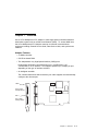
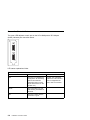
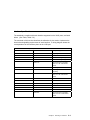
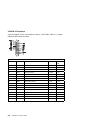
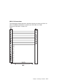
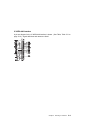
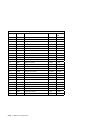
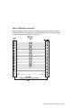
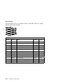
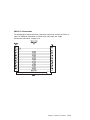
2-Port Multiprotocol PCI Adapter Installation and User's Guide 2-Port Multiprotocol PCI Adapter Installation and User's Guide Note Before using this information and the product it supports, be sure to read the general information under "Product Warranties and Notices" included with your system unit. First Edition (April 1997) The following paragraph does not apply to the United Kingdom or any country where such provisions are inconsistent with local law: THIS PUBLICATION IS PROVIDED “AS IS” WITHOUT WARRANTY OF ANY KIND, EITHER EXPRESS OR IMPLIED, INCLUDING, BUT NOT LIMITED TO, THE IMPLIED WARRANTIES OF MERCHANTABILITY OR FITNESS FOR A PARTICULAR PURPOSE. Some states do not allow disclaimer of express or implied warranties in certain transactions, therefore, this statement may not apply to you. This publication could include technical inaccuracies or typographical errors. Changes are periodically made to the information herein; these changes will be incorporated in new editions of the publication. The manufacturer may make improvements and/or changes in the product(s) and/or the program(s) described in this publication at any time, without notice. It is possible that this publication may contain reference to, or information about, products (machines and programs), programming, or services that are not announced in your country. Such references or information must not be construed to mean that these products, programming, or services will be announced in your country. Any reference to a specific licensed program in this publication is not intended to state or imply that you can use only that licensed program. You can use any functionally equivalent program instead. Requests for technical information about products should be made to your authorized reseller or marketing representative. International Business Machines Corporation 1997. All rights reserved. Note to U.S. Government Users -- Documentation related to restricted rights -- Use, duplication or disclosure is subject to restrictions set forth is GSA ADP Schedule Contract with IBM Corp. Contents Safety Information . . . . . . . . . . . . . . . . . . . . . . . . . . . . . . . . . . . . Handling Static Sensitive Devices Electrostatic Discharge Protection . About This Book Related Publications . . . . . ISO 9000 Trademarks . . . . . . . . . . . . . . . . . . . . . . . . . . . . . . . . . . . . . . . . . . . . . . . . . . . . . . . . . . . . . . . . . . . . . . . . . . . . . . . . . . . . . . . . . . . . . . . . . . . . . . . . . . . . . . . . . . . . . . . . . . . . . . . . . . . . . . . . . . . . . . . . . . . . . . . . . . . . . . . . . . . . . . . . . . . . . . . . . . . . . . . . . . . . . . . . . . . . . . . Chapter 1. Overview Software Requirements . . . . . . . . . . . . . . . . . . . . . . . . . . . . . . . . . . . . . . . . . . . . . . . . . . . . . . . . . . . . . . . . . . . Chapter 2. Preparing for Installation Inventory . . . . . . . . . . . . . . . . . . . . . . . . . . . . . . . . . . . . . . . . . . . . . . . . . . . . . . . . . . . . . . . . . . Chapter 3. Installing Device Driver Software Device Driver Software Installation . . . . . . . Chapter 4. Installing Hardware Installing the Adapter . . . . . . . Troubleshooting . . . . . . . . . . . Verify AIX Hardware Installation Verify Adapter Ports . . . . . . . . Verify AIX Software Installation Chapter 5. Selecting an Interface Connection Status Indicators . . . Interface Specifications . . . . . . V.24/EIA-232 Interface . . . . . VHSI V.24 Connections . . . . The V.35 Interface . . . . . . . VHSI V.35 Connections . . . . V.36/EIA-449 Interface . . . . . VHSI V.36/EIA-449 Connections X.21 Interface . . . . . . . . . . VHSI X.21 Connections . . . . Cable Construction Information . . . . . . . . . . . . . . . . . . . . . . . . . . . . . . . . . . . . . . . . . . . . . . . . . . . . . . . . . . . . . . . . . . . . . . . . . . . . . . . . . . . . . . . . . . . . . . . . . . . . . . . . . . . . . . . . . . . . . . . . . . . . . . . . . . . . . . . . . . . . . . . . . . . . . . . . . . . . . . . . . . . . . . . . . . . . . . . . . . . . . . . . . . . . . . . . . . . . . . . . . v vii vii ix ix ix ix 1-1 1-2 2-1 2-1 3-1 3-1 4-1 4-1 4-2 4-2 4-3 4-3 5-1 5-2 . 5-3 . 5-4 . 5-5 . 5-6 . 5-8 . 5-9 5-11 5-12 5-13 5-14 . . . . . . . . . . . . . . . . . . . . . . . . . . . . . . . . . . . . . . . . . . . . . . . . . . . . . . . . . . . . . . . . . . . . . . . . . . . . . . . . . . . . . . . . . . . . . . . . . . . . . . . . . . . . . . . . . . . . . . . . . . . . . . . . . . . . . . . . . . . . . . . . . . . . . . . . . . . . . . . . . . . . . . . . . . . . . . . . . . . . . . . . . . . . . . . . . . . . . . . . . . . . . . . . . . . . . . . . . . . . . . . . . . . . . . . . . . . . . . . . . . . . . . . . . . . . . . . . . . . . . . . . . . . . . . . . . . . . . . . . . . . . . . . . . . . . . . . . . . . . . . . . . . . . . . . . Appendix A. Technical Specifications . . . . . . . . . . . . . . . . . . . . . . Contents A-1 iii Appendix B. Communications Statements . . . . . . . . . . . . . . . . . . Federal Communications Commission (FCC) Statement . . . . . . . . . . . . European Union (EU) Statement . . . . . . . . . . . . . . . . . . . . . . . . . . International Electrotechnical Commission (IEC) Statement . . . . . . . . . . United Kingdom Telecommunications Safety Requirements . . . . . . . . . . Avis de conformité aux normes du ministère des Communications du Canada Canadian Department of Communications Compliance Statement . . . . . . VCCI Statement . . . . . . . . . . . . . . . . . . . . . . . . . . . . . . . . . . . Radio Protection for Germany . . . . . . . . . . . . . . . . . . . . . . . . . . . iv Installation and User's Guide . . . . . . . . B-1 B-1 B-2 B-2 B-2 B-3 B-3 B-3 B-3 Safety Information DANGER An electrical outlet that is not correctly wired could place hazardous voltage on metal parts of the system or the devices that attach to the system. It is the responsibility of the customer to ensure that the outlet is correctly wired and grounded to prevent an electrical shock. Before installing or removing signal cables, ensure that the power cables for the system unit and all attached devices are unplugged. When adding or removing any additional devices to or from the system, ensure that the power cables for those devices are unplugged before the signal cables are connected. If possible, disconnect all power cables from the existing system before you add a device. Use one hand, when possible, to connect or disconnect signal cables to prevent a possible shock from touching two surfaces with different electrical potentials. During an electrical storm, do not connect cables for display stations, printers, telephones, or station protectors for communication lines. Safety Information v vi Installation and User's Guide Handling Static Sensitive Devices Attention: Static electricity can damage this device and your system unit. To avoid damage, keep this device in its static protective bag until you are ready to install it. To reduce the possibility of electrostatic discharge, follow the precautions listed below. Electrostatic Discharge Protection To prevent electrostatic discharge: Limit your movement. Movement can cause static electricity to build up around you. Handle the device carefully, holding it by its edges or its frame. Do not touch solder joints, pins, or exposed printed circuitry. Do not leave the device where others can handle and possibly damage the device. While the device is still in its anti-static package, touch it to an unpainted metal part of the system unit for at least two seconds. (This drains static electricity from the package and from your body.) Remove the device from its package and install it directly into your system unit without setting it down. If it is necessary to set the device down, place it on its static-protective package. (If your device is an adapter, place it component side up.) Do not place the device on your system unit cover or on a metal table. Take additional care when handling devices during cold weather as heating reduces indoor humidity and increases static electricity. Handling Static Sensitive Devices vii viii Installation and User's Guide About This Book Use this book with your system unit documentation to install a 2-Port Multiprotocol PCI Adapter in a system unit with a PCI-compatible bus. Related Publications This book refers to the documentation that came with your system unit and to the documentation that came with your operating system. ISO 9000 ISO 9000 registered quality systems were used in the development and manufacturing of this product. Trademarks AIX is a registered trademark of International Business Machines Corporation. About This Book ix x Installation and User's Guide Chapter 1. Overview Use a 2-Port Multiprotocol PCI Adapter to make high speed connections between stand alone system units on a Wide Area Network (WAN). To access WAN lines, the 2-Port Multiprotocol PCI Adapter connects via external communications equipment including Channel Service Units, Data Service Units, and synchronous modems. Adapter Features: A 10MHz controller. 512 KB on-board RAM. Two independent Very High-Speed Interface (VHSI) ports. Ports support full duplex communications over a V.24/EIA-232, V.35, V.36/EIA-449, or X.21 interface. Port supports speeds up to 2 Mbps per port depending on the type of interface selected. An intelligent controller. The controller determines which interface your cable supports and automatically configures the relevant port. LED 0 Port 0 (highdensity 36-pin) LED 1 Port 1 (highdensity 36-pin) Chapter 1. Overview 1-1 Software Requirements The 2-Port Multiprotocol PCI Adapter is supported on AIX Version 4.2.1. If support is required on an AIX release other than AIX 4.2.1, please ensure this adapter is supported on that release of AIX prior to install. Contact your support representatives for assistance. 1-2 Installation and User's Guide Chapter 2. Preparing for Installation This section outlines the installation procedure for the 2-Port Multiprotocol PCI Adapter device driver and adapter. The process includes: An inventory of installation materials. The installation of your device driver software. The installation of your adapter. Note: If AIX is not installed on your system unit, install your adapter before you install the operating system. (See Chapter 4, “Installing Hardware” on page 4-1.) When you install AIX, your device driver software automatically installs. If AIX is operating on your system, install your device driver software prior to installing your adapter. (See Chapter 3, “Installing Device Driver Software” on page 3-1.) Inventory To install the 2-Port Multiprotocol PCI Adapter, you need: The adapter. This document, 2-Port Multiprotocol PCI Adapter Installation and User's Guide. The system unit User's Guide. The operating system documentation. A flat-blade screw driver. Media containing device driver software. Chapter 2. Preparing for Installation 2-1 2-2 Installation and User's Guide Chapter 3. Installing Device Driver Software This section explains how to install device driver software. Device Driver Software Installation 1. Be sure you have read Chapter 2, “Preparing for Installation” on page 2-1. Determine if you should install your device driver software first. Determine if you should install your adapter hardware first. If you should install your device driver software first, go to step 2 and continue with this section. If you should install your hardware first, go to Chapter 4, “Installing Hardware” on page 4-1. When you install AIX, your adapter device driver automatically installs. 2. Turn the system unit power on. 3. Log in as root. 4. Insert the media containing the device driver software (example: CD-ROM) into the appropriate media device. 5. Type the following smit devinst and press Enter. 6. The Install Additional Device Software screen highlights the "INPUT device/directory for software" option. 7. Select or type your input device: Press F4 to display the input device list. Select the name of the device (example: CD-ROM) that you are using and press Enter. -- or - In the Entry Field, type the name of the input device you are using and press Enter. 8. The Install Additional Device Software window highlights the SOFTWARE to install option. 9. Press F4 to display the SOFTWARE to install window. Chapter 3. Installing Device Driver Software 3-1 10. Type the following to display the Find window: / 11. Type the following devices.pci.331121b9 and press Enter. (The system finds and highlights this device driver software.) 12. Press PF7 to select the highlighted device driver software. Note: If synchronous data link control (SDLC) emulation is desired, repeat steps 10-12. Type: devices.common.IBM.hdlc.sdlc. 13. Press Enter. Screen appears. Example: 4.2.1.ð devices.pci.331121b9 ALL 14. The Install Additional Device Software screen displays. Entry data fields are automatically updated. Press Enter to accept the data. 15. The ARE YOU SURE window displays. Press Enter to accept the data. 16. The COMMAND STATUS screen appears. The term RUNNING is highlighted to indicate that the install and configure command is in progress. When RUNNING changes to OK, scroll down to the bottom of the page and locate the Installation Summary. After a successful installation, SUCCESS appears in the Result column of the summary at the bottom of the page. 17. Remove the installation media from the drive. 18. Press F10 to exit SMIT. 19. Refer to your system unit documentation to shutdown your system unit. 20. Go to the adapter install procedure, Chapter 4, “Installing Hardware” on page 4-1. 3-2 Installation and User's Guide Chapter 4. Installing Hardware This section provides the guidance necessary to install an adapter. Before you begin, be sure you have read “Handling Static Sensitive Devices” on page vii. Attention: Do not remove the 2-Port Multiprotocol PCI Adapter from its anti-static package at this time. Installing the Adapter 1. Be sure you have read Chapter 2, “Preparing for Installation” on page 2-1. Determine if you should install your adapter hardware first. Determine if you should install your device driver software first. If you should install your adapter hardware first, go to Step 2 and continue with this section. If you should install your device driver software first, go back to Chapter 3, “Installing Device Driver Software” on page 3-1. Return here to install your hardware. 2. Refer to the User's Guide that shipped with your system unit to perform the following: Shutdown your system unit. Install the adapter in your system unit in any available slot. Secure the adapter to the system unit chassis using the bracket screw. 3. After the basic installation is complete, connect your keyboard and mouse to the system unit and connect the cable to the adapter. 4. Turn on your system unit. Go to “Verify AIX Hardware Installation” on page 4-2. Chapter 4. Installing Hardware 4-1 Troubleshooting Initial installation problems are often resolved using a few basic troubleshooting steps: Check Installed Hardware (lsdev) Check Installed Software (lslpp) Verify AIX Hardware Installation 1. To verify your system unit recognizes the 2-Port Multiprotocol PCI Adapter: If necessary, login as root. Type: lsdev -Cs pci | grep 331121b9 and press Enter. 2. Possible Results: If the 2-Port Multiprotocol PCI Adapter did install, the following is an example of the data that appears on your screen: dpmpað Available ð4-ð5 IBM 2-Port Multiprotocol Adapter If you get the above message, go to “Verify Adapter Ports” on page 4-3. If the message on your screen indicates your adapter is Defined instead of Available, shut down your machine. Check the 2-Port Multiprotocol PCI Adapter to insure it is installed correctly. Go to Chapter 4, “Installing Hardware” on page 4-1, and return here and repeat step 1. Note: If the message on your screen indicates your adapter is Defined a second time, it may be necessary to contact your service representative. If no data appears on your screen, two possible problems exist: – Device drivers did not install. – Adapter did not install correctly. If that is not the problem, check your adapter installation. Go to Chapter 3, “Installing Device Driver Software” on page 3-1. 4-2 Installation and User's Guide Verify Adapter Ports 1. To verify your system unit recognizes the ports: If necessary, login as root. Type: lsdev -Cs 331121b9 and press Enter. 2. If the ports are active, the following is an example of the data that appears on your screen: hdlcð Available ð4-ð5-ðð IBM HDLC Network Device Driver hdlc1 Available ð4-ð5-ð1 IBM HDLC Network Device Driver Verify AIX Software Installation 1. Verify the device driver for the 2-Port Multiprotocol PCI Adapter is installed. If necessary, login as root. Type: lslpp -l all | grep 331121b9 and press Enter. 2. Possible Results: If the 2-Port Multiprotocol PCI Adapter device driver is installed, the following is an example of the data that appears. devices.pci.331121b9.com 4.2.1.ð COMMITTED IBM PCI 2-Port Multiprotocol devices.pci.331121b9.diag 4.2.1.ð COMMITTED IBM PCI 2-Port Multiprotocol Adapter (331121b9) Diagnostics devices.pci.331121b9.rte 4.2.1.ð COMMITTED IBM PCI 2-Port Multiprotocol devices.pci.331121b9.com 4.2.1.ð COMMITTED IBM PCI 2-Port Multiprotocol devices.pci.331121b9.rte 4.2.1.ð COMMITTED IBM PCI 2-Port Multiprotocol If this appears when your device drivers are installed, but you continue to have problems, go to Chapter 4, “Installing Hardware” on page 4-1. If no data appears on your screen, the 2-Port Multiprotocol PCI Adapter device driver did not install, return to Chapter 3, “Installing Device Driver Software” on page 3-1. If you continue to experience problems, it may be necessary to call your system support organization. Refer to your operating system documentation for directions. Chapter 4. Installing Hardware 4-3 4-4 Installation and User's Guide Chapter 5. Selecting an Interface The 2-Port Multiprotocol PCI Adapter connects like data terminal equipment (DTE) to devices such as data service units (DSUs) or data communications equipment (DCEs), that support one of the following interfaces: V.24/EIA-232, V.35, V.36/EIA-449, or X.21. Each very high speed integrated port (VHSI) is configured independently. The Standard Interface Cable list below describes the most common connections for each interface. To make your own cable, see “Interface Specifications” on page 5-3. Standard Interface Cables V.24/EIA-232 for the 2-Port Multiprotocol PCI Adapter V.35 for the 2-Port Multiprotocol PCI Adapter V.36/EIA-449 for the 2-Port Multiprotocol PCI Adapter X.21 for the 2-Port Multiprotocol PCI Adapter To use one of the above interfaces, install the appropriate cable. The 2-Port Multiprotocol PCI Adapter recognizes the cable and automatically prepares the port for that interface. Refer to the documentation that came with your networking software for additional port configuration information. Chapter 5. Selecting an Interface 5-1 Connection Status Indicators The green LED adjacent to each port on the 2-Port Multiprotocol PCI Adapter (below) indicates port connection status. LED status explanations follow: Table 5-1. Explanation of LED States LED State Connection Status Action Off The port is not loaded (the configuration file describing protocol and interface parameters was not read by the device driver on the system unit.) Consult your networking software for instructions to load a configuration file and to start a connection. Flash The connection is up and data is being transmitted or received. On The port is active and the connection is good. 5-2 Installation and User's Guide Interface Specifications The standards, compliant with each interface supported on the VHSI ports, are listed below. (See Table, Table 5-2.) The remainder of this section describes the allocation of pins used to implement the electrical and signalling requirements of each interface. A wiring diagram shows the correspondence of the interface pinout to the VHSI port. Table 5-2. Interface Compatibility Interface Standard Compatibility V.24/EIA-232 CCITT V.24 Signalling CCITT V.28 Electrical CCITT X.21bis Electrical and signalling EIA-232-E Electrical and signalling ISO 2110 Connector type for the DCE side of a V.24 VHSI Modem Cable CCITT V.28 Some signals for electrical CCITT V.35 Some signals for electrical and signalling ISO 2593 Connector type for the DCE side of a V.35 VHSI Modem Cable CCITT V.10 Electrical CCITT V.11 Electrical CCITT X.21 Signalling CCITT V.11 Electrical CCITT X.27 Electrical EIA-422-A Electrical ISO 4903 Connector type for the DCE side of an X.21 VHSI Modem Cable V.35 V.36/EIA-449 X.21 Chapter 5. Selecting an Interface 5-3 V.24/EIA-232 Interface A pin-out diagram for the V.24 interface is shown. (See Table, Table 5-3.) Signal definitions and names are listed. Table 5-3. V.24 Interface Signals Pin No. Signal Name Direction CCITT No. 1 PGND Protective Ground Common 101 2 TXD Transmit Data Output 103 3 RXD Receive Data Input 104 4 RTS Request to Send Output 105 5 CTS Clear to Send Input 106 6 DSR Data Set Ready Input 107 7 SGND Signal Ground Common 102 8 DCD Data Carrier Detect Input 109 15 TCLK Transmit Clock (DCE) Input 114 17 RCLK Receive Clock Input 115 18 TEST Local Loopback Activation Output 141 20 DTR Data Terminal Ready Output 108 21 RLB Remote Loopback Output 140 22 RI Ring Indicator Input 125 24 DTECLK Transmit Clock (DTE) Output 113 25 TI Test Indicator Input 142 5-4 Installation and User's Guide VHSI V.24 Connections The wiring diagram below shows the connections required to construct a VHSI V.24 cable. For additional information to construct your own cable, see “Cable Construction Information” on page 5-14. Chapter 5. Selecting an Interface 5-5 The V.35 Interface A pin-out diagram for the V.35 interface is shown. (See Table, Table 5-4 on page 5-7.) Signal definitions and names are listed. 5-6 Installation and User's Guide Table 5-4. V.35 Interface Signals Pin No. Signal Name Direction CCITT No. A PGND Protective Ground Common 101 B SGND Signal Ground Common 102 C RTS Request to Send Output 105 D CTS Clear to Send Input 106 E DSR Data Set Ready Input 107 F DCD Data Carrier Detect Input 109 H DTR Data Terminal Ready Output 108 J RI Ring Indicator Input 125 L TEST Local Loopback Activation Output 141 N RLB Remote Loopback Output 140 P TXD+ Transmit Data Output 103A R RXD+ Receive Data Input 104A S TXD- Transmit Data Output 103B T RXD- Receive Data Input 104B U CLK+ Transmit Clock (DTE) Output 113A V RCLK+ Receive Clock (DCE) Input 115A W CLK- Transmit Clock (DTE) Output 113B X RCLK- Receive Clock (DCE) Input 115B Y TCLK+ Transmit Clock (DCE) Input 114A AA TCLKTransmit Clock (DCE) Output 114B NN TI Test Indicator Input 142 Chapter 5. Selecting an Interface 5-7 VHSI V.35 Connections The wiring diagram below shows the connections required to construct a VHSI V.35 cable. For additional information to construct your own cable, see “Cable Construction Information” on page 5-14. Adapter End Twisted Pairs (Manditory) V.35 Drain Wire Braid 5-8 Installation and User's Guide V.36/EIA-449 Interface A pin-out diagram for the V.36/EIA-449 interface is shown. (See Table, Table 5-5 on page 5-10.) Signal definitions and names are listed. Chapter 5. Selecting an Interface 5-9 Table 5-5. V.36/EIA-449 Interface Signals Pin No. Signal Name Direction CCITT No. Case PGND Protective Ground Common 101 4 TXD+ Transmit Data Output 103A 5 TRXC+ Transmit Clock (DCE) Input 114A 6 RXD+ Receive Data Input 104A 7 RTS+ Request to Send Output 105A 8 RTXC+ Receive Clock (DCE) Input 115A 9 CTS+ Clear to Send Input 106A 10 TEST Local Loopback Activation Output 141A 11 DSR+ Data Set Ready Input 107A 12 DTR+ Data Terminal Ready Output 108A 13 DCD+ Data Carrier Detect Input 109A 14 RLB Remote Loopback Output 140A 15 RI Ring Indicator Input 125A 17 CLK+ Transmit Clock (DTE) Output 113A 18 TI Test Indicator Input 142A 19 GND DTE Common Return Common 102A/B 22 TXD- Transmit Data Output 103B 23 TRXC- Transmit Clock (DCE) Output 114B 24 RXD- Receive Data Input 104B 25 RTS- Request to Send Output 105B 26 RTXC- Receive Clock (DCE) Input 115B 27 CTS- Clear to Send Output 106B 29 DSR- Data Set Ready Input 107B 30 DTR- Data Terminal Ready Output 108B 31 DCD- Data Carrier Detect Input 109B 35 CLK- Transmit Clock (DTE) Output 113B 5-10 Installation and User's Guide VHSI V.36/EIA-449 Connections The wiring diagram below shows the connections required to construct a VHSI V.36/EIA-449 cable. For additional information to construct your own cable, see “Cable Construction Information” on page 5-14. Chapter 5. Selecting an Interface 5-11 X.21 Interface A pin-out diagram for the X.21 interface is shown. (See Table, Table 5-6.) Signal definitions and names are listed. Table 5-6. X.21 Interface Signals Pin No. Signal Name Direction CCITT No. 1/15 PGND Protective Ground Common 101 2 T(A) Transmit Data (+) Output 103A 3 C(A) Control Signal (+) Output 105A 4 R(A) Receive Data (+) Input 104A 5 I(A) Indication (+) Input 109A 6 S(A) Signal Element Timing (+) Input 115A 7 B(A) Byte Timing (+) Input 114A 8 SGND Signal Ground Common 102 9 T(B) Transmit Data (-) Output 103B 10 C(B) Control Signal (-) Output 105B 11 R(B) Receive Data (-) Input 104B 12 I(B) Indication (-) Input 109B 13 S(B) Signal Element Timing (-) 14 B(B) Byte Timing (-) 5-12 Installation and User's Guide Input Input 115B 114B VHSI X.21 Connections The wiring diagram below shows the connections required to construct a VHSI X.21 cable. For additional information to construct your own cable, see “Cable Construction Information” on page 5-14. Chapter 5. Selecting an Interface 5-13 Cable Construction Information If you plan to construct your own VHSI cables, be sure to observe the guidelines below. Wire Gauge, Grounding, and Pairing Use 28 AWG 7-strand wire with 0.020--0.028 inch insulation. The chassis must be grounded both by a drain wire and by the braid; both must be connected to the connector case and shell at each end of the cable. The braid must be connected through its full circumference. Wires identified under the heading "Twisted Pairs" must be paired. If you do not install twisted pairs correctly, the cable does not work. Type of Connectors: The VHSI port accepts a high density 36-pin male cable connector. The types of connector used on the interface-specific end of the cable are: Table 5-7. Connector Types Interface Connector V.35 Type M V.24 DB25 V.36/EIA-449 DB37 X.21 DB15 5-14 Installation and User's Guide Appendix A. Technical Specifications Technical Data PCI bus compatible (32-bit slot) Hitachi 64570 HDLC controller at 10 MHz 512 KB of DRAM Hardware Installation Automatic configuration of interrupt request level setting and memory address 32-bit memory access External Interface Two 36-pin female VHSI ports connect to 36-pin high-density male connectors Support for V.24/EIA-232, V.35, and V.36/EIA-449 X.21 with V.11 (X.27) signalling External clocking Performance 2 Mbps full duplex per physical port Power Requirements 1.25 A @ +5V 50 mA @ +12V 25 mA @ -12V Environmental Requirements Operating temperature: 0DEGC to 50DEGC Operating humidity: 0 to 90% (non-condensing) Barometric operating pressure: 86 to 106 kPascals Maximum tolerance in power supply variation: +5% to -5% Appendix A. Technical Specifications A-1 A-2 Installation and User's Guide Appendix B. Communications Statements The following statement applies to this product. The statement for other products intended for use with this product appears in their accompanying documentation. Federal Communications Commission (FCC) Statement Note: The 2-Port Multiprotocol PCI Adapter has been tested and found to comply with the limits for a Class B digital device, pursuant to Part 15 of the FCC Rules. These limits are designed to provide reasonable protection against harmful interference in a residential installation. This equipment generates, uses, and can radiate radio frequency energy and, if not installed and used in accordance with the instructions, may cause harmful interference to radio communications. However, there is no guarantee that interference will not occur in a particular installation. If this equipment does cause harmful interference to radio or television reception, which can be determined by turning the equipment off and on, the user is encouraged to try to correct the interference by one or more of the following measures: Reorient or relocate the receiving antenna. Increase the separation between the equipment and receiver. Connect the equipment into an outlet on a circuit different from that to which the receiver is connected. Consult an authorized dealer or service representative for help. Properly shielded and grounded cables and connectors must be used in order to meet FCC emission limits. Proper cables and connectors are available from authorized dealers. Neither the provider nor the manufacturer are responsible for any radio or television interference caused by using other than recommended cables and connectors or by unauthorized changes or modifications to this equipment. Unauthorized changes or modifications could void the user's authority to operate the equipment. This device complies with Part 15 of the FCC Rules. Operation is subject to the following two conditions: (1) this device may not cause harmful interference, and (2) this device must accept any interference received, including interference that may cause undesired operation. Responsible Party: International Business Machines Corporation New Orchard Road Armonk, New York 10504 Telephone: (919) 543-2193 Appendix B. Communications Statements B-1 European Union (EU) Statement This product is in conformity with the protection requirements of EU Council Directive 89/336/EEC on the approximation of the laws of the Member States relating to electromagnetic compatibility. The manufacturer cannot accept responsibility for any failure to satisfy the protection requirements resulting from a non-recommended modification of the product, including the fitting of option cards supplied by third parties. Consult with your dealer or sales representative for details on your specific hardware. This product has been tested and found to comply with the limits for Class B Information Technology Equipment according to CISPR 22 / European Standard EN 55022. The limits for Class B equipment were derived for typical residential environments to provide reasonable protection against interference with licensed communication devices. International Electrotechnical Commission (IEC) Statement This product has been designed and built to comply with IEC Standard 950. United Kingdom Telecommunications Safety Requirements This equipment is manufactured to the International Safety Standard EN60950 and as such is approved in the UK under the General Approval Number NS/G/1234/J/100003 for indirect connection to the public telecommunication network. The network adapter interfaces housed within this equipment are approved separately, each one having its own independent approval number. These interface adapters, supplied by the manufacturer, do not use or contain excessive voltages. An excessive voltage is one which exceeds 70.7 V peak ac or 120 V dc. They interface with this equipment using Safe Extra Low Voltages only. In order to maintain the separate (independent) approval of the manufacturer's adapters, it is essential that other optional cards, not supplied by the manufacturer, do not use main voltages or any other excessive voltages. Seek advice from a competent engineer before installing other adapters not supplied by the manufacturer. B-2 Installation and User's Guide Avis de conformité aux normes du ministère des Communications du Canada Cet appareil numérique de la classe B respecte toutes les exigences du Réglement sur le matériel brouilleur du Canada. Canadian Department of Communications Compliance Statement This Class B digital apparatus meets the requirements of the Canadian Interference-Causing Equipment Regulations. VCCI Statement The following is a summary of the VCCI Japanese statement in the box above. This is a Class B product based on the standard of the Voluntary Control Council for Interference from Information Technology Equipment (VCCI). If this is used near a radio or television receiver in a domestic environment, it may cause radio interference. Install and use the equipment according to the instruction manual. When used near a radio or TV receiver, it may become the cause of radio interference. Read the instructions for correct handling. Radio Protection for Germany Dieses Gerät ist berechtigt in Übereinstimmung mit dem deutschen EMVG vom 9.Nov.92 das EG–Konformitätszeichen zu führen. Der Aussteller der Konformitätserklärung ist die IBM Germany. Dieses Gerät erfüllt die Bedingungen der EN 55022 Klasse B. Appendix B. Communications Statements B-3 B-4 Installation and User's Guide Part Number: 93H5648 Printed in U.S.A. 93H5648


![HiSoft Devpac 3 (text version) [1992] [Manual: PDF]](http://vs1.manualzilla.com/store/data/005668901_1-67cf8256fc448cd2edf58a11a6ec729e-150x150.png)