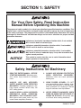
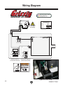
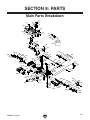
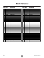
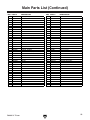
1
MODEL G0689 13" PLANER WITH BUILT-IN DUST COLLECTION OWNER'S Manual Copyright © SEPTEMBER, 2008 By Grizzly Industrial, Inc. Warning: No portion of this manual may be reproduced in any shape Or form without the written approval of Grizzly Industrial, inc. #JB11086 printed in CHINA 4HISMANUALPROVIDESCRITICALSAFETYINSTRUCTIONSONTHEPROPERSETUP OPERATIONMAINTENANCEANDSERVICEOFTHISMACHINEEQUIPMENT &AILURETOREADUNDERSTANDANDFOLLOWTHEINSTRUCTIONSGIVENINTHIS MANUALMAYRESULTINSERIOUSPERSONALINJURYINCLUDINGAMPUTATION ELECTROCUTIONORDEATH 4HEOWNEROFTHISMACHINEEQUIPMENTISSOLELYRESPONSIBLEFORITS SAFEUSE4HISRESPONSIBILITYINCLUDESBUTISNOTLIMITEDTOPROPER INSTALLATIONINASAFEENVIRONMENTPERSONNELTRAININGANDUSAGE AUTHORIZATIONPROPERINSPECTIONANDMAINTENANCEMANUALAVAILABILITY ANDCOMPREHENSIONAPPLICATIONOFSAFETYDEVICESBLADECUTTERINTEG RITYANDTHEUSAGEOFPERSONALPROTECTIVEEQUIPMENT 4HEMANUFACTURERWILLNOTBEHELDLIABLEFORINJURYORPROPERTYDAMAGE FROMNEGLIGENCEIMPROPERTRAININGMACHINEMODIFICATIONSORMISUSE 3OMEDUSTCREATEDBYPOWERSANDINGSAWINGGRINDINGDRILLINGAND OTHERCONSTRUCTIONACTIVITIESCONTAINSCHEMICALSKNOWNTOTHE3TATE OF#ALIFORNIATOCAUSECANCERBIRTHDEFECTSOROTHERREPRODUCTIVE HARM3OMEEXAMPLESOFTHESECHEMICALSARE s ,EADFROMLEADBASEDPAINTS s #RYSTALLINESILICAFROMBRICKSCEMENTANDOTHERMASONRYPRODUCTS s !RSENICANDCHROMIUMFROMCHEMICALLYTREATEDLUMBER 9OURRISKFROMTHESEEXPOSURESVARIESDEPENDINGONHOWOFTENYOU DOTHISTYPEOFWORK4OREDUCEYOUREXPOSURETOTHESECHEMICALS 7ORKINAWELLVENTILATEDAREAANDWORKWITHAPPROVEDSAFETYEQUIP MENTSUCHASTHOSEDUSTMASKSTHATARESPECIALLYDESIGNEDTOFILTER OUTMICROSCOPICPARTICLES Table of Contents INTRODUCTION................................................ 2 Manual Accuracy............................................ 2 Contact Info.................................................... 2 Functional Overview....................................... 2 Identification.................................................... 3 SECTION 1: SAFETY........................................ 6 Safety Instructions for Machinery................... 6 Additional Safety Instructions for Planers....... 8 SECTION 2: CIRCUIT REQUIREMENTS......... 9 110V Operation............................................... 9 SECTION 3: SETUP........................................ 10 Setup Safety................................................. 10 Unpacking..................................................... 10 Inventory....................................................... 10 Clean Up....................................................... 11 Site Considerations....................................... 11 Assembly...................................................... 12 Test Run....................................................... 12 Mounting....................................................... 13 SECTION 4: OPERATIONS............................ 14 Operation Safety........................................... 14 Basic Controls............................................... 14 ON/OFF Switch............................................. 15 Reset Button................................................. 15 Depth-of-Cut................................................. 16 Elevation Lock.............................................. 17 Basic Operations.......................................... 18 Planing Tips.................................................. 18 Wood Characteristics.................................... 19 Wood Types.................................................. 20 SECTION 5: ACCESSORIES.......................... 21 SECTION 6: MAINTENANCE.......................... 23 Schedule....................................................... 23 Cleaning........................................................ 23 Lubrication.................................................... 23 SECTION 7: SERVICE.................................... 24 Troubleshooting............................................ 24 Knife Replacement....................................... 25 Motor............................................................. 27 Drive Belt...................................................... 28 Impeller Belt.................................................. 29 Feed Rollers................................................. 29 Extension Wing/Table Alignment.................. 30 Elevation Lock Adjustment........................... 30 Thickness Stop Calibration........................... 31 Wiring Diagram............................................. 32 SECTION 8: PARTS........................................ 33 Main Parts Breakdown.................................. 33 Main Parts List............................................. 34 Base Parts Breakdown................................. 36 Warning Labels Breakdown and List............ 38 WARRANTY AND RETURNS......................... 41 INTRODUCTION Manual Accuracy Functional Overview We are proud to offer this manual with your new machine! We've made every effort to be exact with the instructions, specifications, drawings, and photographs of the machine we used when writing this manual. However, sometimes errors do happen and we apologize for them. The Model G0689 Planer allows the user to plane material from the surface of boards in precise increments. The depth-of-cut is adjusted with the cutterhead elevation crank and is measured by the cutterhead elevation scale or the depth-of-cut gauge. One turn of the crank raises or lowers the cutterhead 1⁄16". Also, owing to our policy of continuous improvement, your machine may not exactly match the manual. If you find this to be the case, and the difference between the manual and machine leaves you in doubt, immediately call our technical support for updates or clarification. For your convenience, we always keep current Grizzly manuals and most updates available on our website at www.grizzly.com. Any updates to your machine will be reflected in these documents as soon as they are complete. Visit our site often to check for the latest updates! Once the depth-of-cut is adjusted, the operator feeds the board into the infeed roller which pulls the board into the cutterhead, where material is removed. The outfeed roller then pulls the board away from the cutterhead. After the board is completely free from the outfeed roller, it can be returned to the infeed side of the machine. Larger workpieces can be passed across the return rollers on top of the machine. The depth-of-cut is again adjusted, and the process is continued until the desired board thickness is reached. Contact Info We stand behind our machines. If you have any service questions, parts requests or general questions about the machine, please call or write us at the location listed below. Grizzly Industrial, Inc. 1203 Lycoming Mall Circle Muncy, PA 17756 Phone: (570) 546-9663 Fax: (800) 438-5901 E-Mail: [email protected] If you have any comments regarding this manual, please write to us at the address below: Grizzly Industrial, Inc. /O Technical Documentation Manager P.O. Box 2069 Bellingham, WA 98227-2069 Email: [email protected] C -2- G0689 13" Planer Identification B C A D E F K G J H I Figure 1. Identification. A. Carrying Handle B. Return Rollers C. Cutterhead Elevation Crank D. Reset Button E.Depth-of-cut Gauge F.Thickness Stop G.ON/OFF Switch H.Infeed Extension Wing I.Outfeed Extension Wing J.Platen K. Cutterhead Elevation Scale G0689 13" Planer -3- MACHINE DATA SHEET 8jhidbZgHZgk^XZ/*,%*)+".++(IdDgYZg8Vaa/-%%*'("),,,;Vm/-%%)(-"*.%& MODEL G0689 13" PLANER WITH BUILT-IN DUST COLLECTION Product Dimensions: LZ^\]i############################################################################################################################################################################# --aWh# AZc\i]$L^Yi]$=Z^\]i####################################################################################################################################'+&¿'m')&¿'m'& ;ddiEg^ciAZc\i]$L^Yi]######################################################################################################################################'),¿&+m&((¿- Shipping Dimensions: IneZ###########################################################################################################################################################################8VgYWdVgY 8dciZci########################################################################################################################################################################## BVX]^cZ LZ^\]i############################################################################################################################################################################## .*aWh# AZc\i]$L^Yi]$=Z^\]i############################################################################################################################################ '-m&+m'& Electrical: Hl^iX]#####################################################################################################################################################DC$D;;HV[ZinId\\aZ 8dgYAZc\i]##########################################################################################################################################################################-[i# 8dgY<Vj\Z################################################################################################################################################################## &)6L< GZXdbbZcYZY7gZV`ZgH^oZ############################################################################################################################################### '%6 Eaj\>cXajYZY########################################################################################################################################################################NZh Motors: Main IneZ################################################################################################################################################ Jc^kZghVa7gjh]IneZ =dghZedlZg###############################################################################################################################################################'=E KdaiV\Z##################################################################################################################################################################### &&%K E]VhZ######################################################################################################################################################################H^c\aZ 6beh########################################################################################################################################################################## &*6 HeZZY############################################################################################################################################################&,!*%%GEB 8nXaZ######################################################################################################################################################################## +%=o CjbWZgD[HeZZYh##########################################################################################################################################################& EdlZgIgVch[Zg############################################################################################################################################## K"7Zai9g^kZ 7ZVg^c\h#####################################################################################################################################H]^ZaYZYVcYAjWg^XViZY Main Specifications: Operation Information BVm#8jiL^Yi]############################################################################################################################################################ &( BVm#8ji=Z^\]i############################################################################################################################################################# + B^c#HidX`AZc\i]######################################################################################################################################################## &* B^c#HidX`L^Yi]######################################################################################################################################################## &(¿+) BVm#HidX`I]^X`cZhh################################################################################################################################################### + Cd#D[8jihEZg>cX]#####################################################################################################################################################,% Cd#D[8jihEZgB^cjiZ##########################################################################################################################################&+!%%% 8jiiZg]ZVYHeZZY############################################################################################################################################-%%%GEB EaVc^c\;ZZYGViZ################################################################################################################################################ &.;EB BVm#8ji9Zei]EaVc^c\;jaaL^Yi]############################################################################################################################# &¿&+ BVm#8ji9Zei]EaVc^c\*>cX]L^YZ7dVgY############################################################################################################### (¿(' Model G0689 -4- Page 1 of 2 G0689 13" Planer Cutterhead Info 8jiiZg]ZVYIneZ########################################################################################################################################## HigV^\]i@c^[Z 8jiiZg]ZVY9^V############################################################################################################################################################## ' Cd#d[@c^kZh###################################################################################################################################################################' @c^[ZIneZ############################################################################################################################HigV^\]i9djWaZ:Y\ZY=HH @c^[ZH^oZAZc\i]######################################################################################################################################################## &( @c^[ZH^oZL^Yi]######################################################################################################################################################### &*¿(' @c^[ZH^oZI]^X`cZhh################################################################################################################################################### &¿&+ @c^[Z6Y_jhibZci################################################################################################################################### <^WhVcYHeg^c\h Table Info IVWaZ7ZYH^oZAZc\i]############################################################################################################################################# &%&¿) IVWaZ7ZYH^oZL^Yi]################################################################################################################################################## &( :miZch^dcL^c\H^oZAZc\i]#################################################################################################################################### ')*¿- :miZch^dcL^c\H^oZL^Yi]######################################################################################################################################### &( Construction IVWaZ8dchigjXi^dc###################################################################################################################HiZZaVcY8Vhi6ajb^cjb 7dYn8dchigjXi^dc#####################################################################################################################################################HiZZa 8jiiZg]ZVY6hhZbWan8dchigjXi^dc###########################################################################################################################HiZZa >c[ZZYGdaaZg8dchigjXi^dc############################################################################################################################HiZZa$GjWWZg Dji[ZZYGdaaZg8dchigjXi^dc#########################################################################################################################HiZZa$GjWWZg EV^ci########################################################################################################################################################################:edmn Other 9jhiEdgiH^oZ############################################################################################################################################################ '&¿' BZVhjgZbZciHXVaZ################################################################################################################################# >cX]VcYBZig^X Other Specifications: 8djcignD[Dg^\^c############################################################################################################################################################## 8]^cV LVggVcin########################################################################################################################################################################### &NZVg HZg^VaCjbWZgAdXVi^dc#####################################################################################################BVX]^cZ>9aVWZadcided[BVX]^cZ 6hhZbWanI^bZ######################################################################################################################################################### '%b^cjiZh Features: 7j^ai"^c9jhi8daaZXi^dc IdeBdjciZYGZijgcGdaaZgh :migVAVg\Z;daY"9dlcIVWaZ:miZch^dch IdeBdjciZY9Zei]6Y_jhibZci I]ZgbVaDkZgadVYEgdiZXi^dc 8dckZc^Zci8Vggn=VcYaZhdcH^YZ =Z^\]iHXVaZ Model G0689 G0689 13" Planer Page 2 of 2 -5- 3%#4)/.3!&%49 &OR9OUR/WN3AFETY2EAD)NSTRUCTION -ANUAL"EFORE/PERATINGTHIS-ACHINE 4HEPURPOSEOFSAFETYSYMBOLSISTOATTRACTYOURATTENTIONTOPOSSIBLEHAZARDOUSCONDITIONS4HIS MANUALUSESASERIESOFSYMBOLSANDSIGNALWORDSINTENDEDTOCONVEYTHELEVELOFIMPORTANCE OFTHESAFETYMESSAGES4HEPROGRESSIONOFSYMBOLSISDESCRIBEDBELOW2EMEMBERTHATSAFETY MESSAGESBYTHEMSELVESDONOTELIMINATEDANGERANDARENOTASUBSTITUTEFORPROPERACCIDENT PREVENTIONMEASURES )NDICATESANIMMINENTLYHAZARDOUSSITUATIONWHICHIFNOTAVOIDED 7),,RESULTINDEATHORSERIOUSINJURY )NDICATESAPOTENTIALLYHAZARDOUSSITUATIONWHICHIFNOTAVOIDED #/5,$RESULTINDEATHORSERIOUSINJURY )NDICATESAPOTENTIALLYHAZARDOUSSITUATIONWHICHIFNOTAVOIDED -!9RESULTINMINORORMODERATEINJURY)TMAYALSOBEUSEDTOALERT AGAINSTUNSAFEPRACTICES ./4)#% 4HISSYMBOLISUSEDTOALERTTHEUSERTOUSEFULINFORMATIONABOUT PROPEROPERATIONOFTHEMACHINE Safety Instructions for Machinery 3AFETY)NSTRUCTIONSFOR-ACHINERY 2%!$4(%%.4)2%-!.5!,"%&/2% 34!24).'-!#().%29BVX]^cZgnegZh" Zcih hZg^djh ^c_jgn ]VoVgYh id jcigV^cZY jhZgh# !,7!93 53% (%!2).' 02/4%#4)/. 7(%. /0%2!4).' -!#().%29 BVX]^cZgn cd^hZ XVc XVjhZ eZgbVcZci ]ZVg^c\adhh# !,7!93 53% !.3) !002/6%$ 3!&%49',!33%37(%./0%2!4).' -!#().%29 :kZgnYVn ZnZ\aVhhZh dcan ]VkZ ^beVXi gZh^hiVci aZchZh·i]Zn VgZ CDIhV[Zin\aVhhZh# 7%!2 02/0%2 !00!2%, 9D CDI lZVgaddhZXadi]^c\!\adkZh!cZX`i^Zh!g^c\h! dg _ZlZagn i]Vi XVc XViX] ^c bdk^c\ eVgih# LZVg egdiZXi^kZ ]V^g XdkZg^c\ id XdciV^c adc\]V^gVcYlZVgcdc"ha^e[ddilZVg# !,7!93 7%!2 ! .)/3( !002/6%$ 2%30)2!4/2 7(%. /0%2!4).' -!#().%29 4(!4 02/$5#%3 $534 BdhiineZhd[YjhilddY!bZiVa!ZiX#XVc XVjhZhZkZgZgZhe^gVidgn^aacZhhZh# .%6%2 /0%2!4% -!#().%29 7(%. 4)2%$/25.$%24(%).&,5%.#%/& $25'3/2!,#/(/,7ZbZciVaanVaZgi ViVaai^bZhl]Zcgjcc^c\bVX]^cZgn# -6- G0689 13" Planer 3AFETY)NSTRUCTIONSFOR-ACHINERY /.,9 !,,/7 42!).%$ !.$ 02/0 %2,9 350%26)3%$ 0%23/..%, 4/ /0%2!4% -!#().%29 BV`Z hjgZ deZgVi^dc^chigjXi^dchVgZhV[ZVcYXaZVgan jcYZghiddY# +%%0#(),$2%.!.$6)3)4/23!7!9 @ZZe Vaa X]^aYgZc VcY k^h^idgh V hV[Z Y^h" iVcXZ[gdbi]Zldg`VgZV# -!+% 7/2+3(/0 #(),$02//& JhZ eVYadX`h! bVhiZg hl^iX]Zh! VcY gZbdkZ hiVgihl^iX]`Znh# .%6%2 ,%!6% 7(%. -!#().% )3 25..).'IjgcedlZg/&&VcYVaadlVaa bdk^c\ eVgih id XdbZ id V XdbeaZiZ hide WZ[dgZaZVk^c\bVX]^cZjcViiZcYZY# $/ ./4 53% ). $!.'%2/53 %.6)2/.-%.43 9D CDI jhZ bVX]^c" Zgn ^c YVbe! lZi adXVi^dch! dg l]ZgZ Vcn [aVbbVWaZdgcdm^djh[jbZhbVnZm^hi# +%%07/2+!2%!#,%!.!.$7%,, ,)'(4%$8ajiiZgVcYYVg`h]VYdlhbVn XVjhZVXX^YZcih# 53% ! '2/5.$%$ %84%.3)/. #/2$ 2!4%$&/24(%-!#().%!-0%2!'% <gdjcYZY XdgYh b^c^b^oZ h]dX` ]VoVgYh# JcYZgh^oZY XdgYh XgZViZ ZmXZhh^kZ ]ZVi# 6alVnhgZeaVXZYVbV\ZYZmiZch^dcXdgYh# !,7!93 $)3#/..%#4 &2/- 0/7%2 3/52#% "%&/2% 3%26)#).' -!#().%29# BV`Z hjgZ hl^iX] ^h ^c D;; edh^i^dcWZ[dgZgZXdccZXi^c\# -!).4!). -!#().%29 7)4( #!2% @ZZeWaVYZhh]VgeVcYXaZVc[dgWZhiVcY hV[ZhieZg[dgbVcXZ#;daadl^chigjXi^dch[dg ajWg^XVi^c\VcYX]Vc\^c\VXXZhhdg^Zh# -!+% 352% '5!2$3 !2% ). 0,!#% !.$ 7/2+ #/22%#4,9 "%&/2% 53).'-!#().%29 G0689 13" Planer 2%-/6% !$*534).' +%93 !.$ 72%.#(%3BV`ZV]VW^id[X]ZX`^c\[dg `Znh VcY VY_jhi^c\ lgZcX]Zh WZ[dgZ ijgc" ^c\bVX]^cZgn/.# #(%#+ &/2 $!-!'%$ 0!243 "%&/2%53).'-!#().%298]ZX`[dg W^cY^c\dgb^hVa^\cZYeVgih!Wgd`ZceVgih! addhZ Wdaih! VcY Vcn di]Zg XdcY^i^dch i]Vi bVn ^beV^g bVX]^cZ deZgVi^dc# GZeV^g dg gZeaVXZYVbV\ZYeVgihWZ[dgZdeZgVi^dc# 53% 2%#/--%.$%$ !##%33/2)%3 GZ[Zgidi]Z^chigjXi^dcbVcjVa[dggZXdb" bZcYZY VXXZhhdg^Zh# >begdeZg VXXZhhd" g^Zh^cXgZVhZg^h`d[^c_jgn# $/ ./4 &/2#% -!#().%29 Ldg` Vi i]ZheZZY[dgl]^X]i]ZbVX]^cZdgVXXZh" hdgnlVhYZh^\cZY# 3%#52% 7/2+0)%#% JhZ XaVbeh dg V k^hZ id ]daY i]Z ldg`e^ZXZ l]Zc egVXi^" XVa# 6 hZXjgZY ldg`e^ZXZ egdiZXih ndjg ]VcYhVcY[gZZhWdi]]VcYhiddeZgViZi]Z bVX]^cZ# $/ ./4 /6%22%!#( BV^ciV^c hiVW^a^in VcYWVaVcXZViVaai^bZh# -!.9 -!#().%3 #!. %*%#4 7/2+0)%#%3 4/7!2$ /0%2!4/2 @cdlVcYVkd^YXdcY^i^dchi]ViXVjhZi]Z ldg`e^ZXZid`^X`WVX`# !,7!93 ,/#+ -/"),% "!3%3 )& 53%$ "%&/2% /0%2!4).' -!#().%29# #%24!). $534 -!9 "% (!:!2$/53 id i]Z gZhe^gVidgn hnhiZbh d[ eZdeaZ VcY Vc^bVah!ZheZX^Vaan[^cZYjhi#7ZVlVgZd[ i]Z ineZ d[ Yjhi ndj VgZ ZmedhZY id VcY ValVnhlZVgVgZhe^gVidgYZh^\cZYid[^aiZg i]ViineZd[Yjhi# -7- Additional Safety Instructions for Planers 1. Instruction manual. This machine presents significant safety hazards to untrained users. Read/understand this entire manual before starting the planer. 2. REACHING INSIDE PLANER. Never reach inside planer or remove cover when the planer is connected to power. 3. Infeed clearance Safety. The infeed roller is designed to pull material into the cutterhead. Always keep hands, clothing, and long hair away from the infeed roller during operation to prevent being pulled in. 4. Body position while operating. The workpiece may kickback during operation. To avoid getting hit, stand to the side of the planer during the entire operation. 5. Planing correct material. Only plane natural wood stock with this planer. DO NOT plane MDF, plywood, laminates, metal, stone, plastic, drywall, backerboard, or synthetic products. 8. Cutting limitations. The planer may kickback a workpiece at the operator or be damaged if pushed beyond these limits. • Maximum Depth-of-cut <5" Wide..........3⁄32" • Maximum Depth-of-cut >5" Wide..........1⁄16" • Minimum Board Length.........................15" • Minimum Board Thickness...................13⁄64" • Maximum # of Boards at One Time..........1 9. CLEAN STOCK. Planing stock with nails, staples, or loose knots MAY cause debris to kick out at the operator and WILL damage your cutters when they contact the cutterhead. Always thoroughly inspect and prepare stock to avoid these hazards. 10. Removing jammed workpieces. To avoid serious injury, always stop the planer and disconnect power before removing jammed workpieces. 11. DULL/DAMAGED KNIVES. The planer may kickback a workpiece at the operator or give poor finish results if it is operated with dull or damaged knives. 6. GRAIN DIRECTION. Planing across the grain is hard on the planer and may cause workpiece kickback. Always plane in the same direction or at a slight angle with the wood grain. 12. Unplugging during adjustments. When connected to power, the planer can be accidentally turned ON. Always disconnect power when servicing or adjusting the components of the planer. 7. LOOKING INSIDE PLANER. Wood chips fly around inside the planer at a high rate of speed. DO NOT look inside the planer or remove guards/covers during operation. 13. WORKPIECE CLEARANCE. Always verify workpiece has enough room to exit the planer before starting. Like all machinery there is potential danger when operating this machine. Accidents are frequently caused by lack of familiarity or failure to pay attention. Use this machine with respect and caution to lessen the possibility of operator injury. If normal safety precautions are overlooked or ignored, serious personal injury may occur. -8- No list of safety guidelines can be complete. Every shop environment is different. Always consider safety first, as it applies to your individual working conditions. Use this and other machinery with caution and respect. Failure to do so could result in serious personal injury, damage to equipment, or poor work results. G0689 13" Planer SECTION 2: CIRCUIT REQUIREMENTS 110V Operation Serious personal injury could occur if you connect the machine to power before completing the setup process. DO NOT connect the machine to the power until instructed later in this manual. Power Connection Device The Model G0689 comes with a 5-15 plug, similar to Figure 2, to connect the machine to power. <gdjcY^c\Egdc\^h Adc\Zhid[i]ZI]gZZ Egdc\h 8jggZci 8Vggn^c\Egdc\h Electrocution or fire could result if machine is not grounded and installed in compliance with electrical codes. Compliance MUST be verified by a qualified electrician! <gdjcYZY DjiaZi Figure 2. Typical 5-15 plug and receptacle. Full Load Amperage Draw Motor Draw............................................. 15 Amps Circuit Requirements You MUST connect your machine to a grounded circuit that is rated for the amperage given below. Never replace a circuit breaker on an existing circuit with one of higher amperage without consulting a qualified electrician to ensure compliance with wiring codes. If you are unsure about the wiring codes in your area or you plan to connect your machine to a shared circuit, consult a qualified electrician. Recommended Circuit Size.................... 20 Amps This machine MUST have a ground prong in the plug to help ensure that it is grounded. DO NOT remove ground prong from plug to fit into a two-pronged outlet! If the plug will not fit the outlet, have the proper outlet installed by a qualified electrician. Extension Cords We do not recommend using extension cords, but if you find it absolutely necessary: •Use at least a 14 gauge cord that does not exceed 50 feet in length! •The extension cord must have a ground wire and plug pin. •A qualified electrician MUST size cords over 50 feet long to prevent motor damage. G0689 13" Planer -9- SECTION 3: SETUP Setup Safety This machine presents serious injury hazards to untrained users. Read through this entire manual to become familiar with the controls and operations before starting the machine! Inventory The following is a description of the main components shipped with your machine. Lay the components out to inventory them. Items: (Figure 3) Qty A.. Planer (Not Shown)..................................... 1 B.. Magnets....................................................... 2 C.. Dust Collection Bag..................................... 1 D.. Bag Clamp................................................... 1 E.. Cap Screw M6-1 x 20 (Crank)..................... 1 F..Lock Washer 6mm (Crank)......................... 1 G.. Elevation Crank........................................... 1 H..Hex Wrench 4mm........................................ 1 Wear safety glasses during the entire setup process! Unpacking C D B E Your machine was carefully packaged for safe transportation. Remove the packaging materials from around your machine and inspect it. If you discover the machine is damaged, please immediately call Customer Service at (570) 546-9663 for advice. Save the containers and all packing materials for possible inspection by the carrier or its agent. Otherwise, filing a freight claim can be difficult. F G H Figure 3. Inventory. If any nonproprietary parts are missing (e.g. a nut or a washer), we will gladly replace them; or for the sake of expediency, replacements can be obtained at your local hardware store. When you are completely satisfied with the condition of your shipment, inventory the contents. SUFFOCATION HAZARD! Immediately discard all plastic bags and packing materials to eliminate choking/suffocation hazards for children and animals. -10- G0689 13" Planer Clean Up The unpainted surfaces are coated with a waxy oil to prevent corrosion during shipment. Remove this protective coating with a solvent cleaner or degreaser, such as shown in Figure 4. For thorough cleaning, some parts must be removed. For optimum performance, clean all moving parts or sliding contact surfaces. Avoid chlorine-based solvents, such as acetone or brake parts cleaner that may damage painted surfaces. Always follow the manufacturer’s instructions when using any type of cleaning product. Gasoline and petroleum products have low flash points and can explode or cause fire if used to clean machinery. DO NOT use these products to clean the machinery. Site Considerations Workbench Load Refer to the Machine Data Sheet for the weight and footprint specifications of your machine. Some workbenches may require additional reinforcement to support both the machine and the workpiece. Placement Location Consider existing and anticipated needs, size of material to be processed through each machine, and space for auxiliary stands, work tables or other machinery when establishing a location for your new machine. See Figure 5 for the minimum working clearances. 24 1⁄2" Many cleaning solvents are toxic if inhaled. Minimize your risk by only using these products in a well ventilated area. G2544—Solvent Cleaner & Degreaser H9692—Orange Power Degreaser Great products for removing shipping grease. 261⁄2" Figure 5. Minimum working clearances. Children and visitors may be seriously injured if unsupervised around this machine. Lock entrances to the shop or disable start switch or power connection to prevent unsupervised use. Figure 4. Cleaner/degreasers available from Grizzly. G0689 13" Planer -11- Assembly To attach the elevation crank assembly: 1. Align the flat portion inside the crank bore with the flat portion on the shaft, then place the crank assembly on the elevation shaft. 2.Thread the M6-1 x 20 button head screw with the flat washer through the crank and into the shaft to secure the crank in place, as shown in Figure 6. DO NOT over-tighten. Screw & Washer Test Run Once the assembly is complete, test run your machine to make sure it runs properly and is ready for regular operation. The test run consists of verifying the following: 1) The motor powers up and runs correctly, and 2) the safety disabling key on the switch works correctly. If, during the test run, you cannot easily locate the source of an unusual noise or vibration, stop using the machine immediately, then review Troubleshooting on Page 24. If you still cannot remedy a problem, contact our Tech Support at (570) 546-9663 for assistance. To test run the machine: 1. Make sure you have read the safety instructions at the beginning of the manual and that the machine is setup properly. Crank Figure 6. Attaching crank. 3. Attach the dust collection bag to the planer dust outlet by sliding the clamp over the mouth of the bag, placing the bag over the dust outlet, then positioning and locking the clamp over both the bag and the outlet, as shown in Figure 7. 2. Make sure all tools and objects used during setup are cleared away from the machine. 3. Connect the machine to the power source. 4. Verify that the machine is operating correctly by turning the machine ON. —When operating correctly, the machine runs smoothly with little or no vibration or rubbing noises. —Investigate and correct strange or unusual noises or vibrations before operating the machine further. Always disconnect the machine from power when investigating or correcting potential problems. Figure 7. Dust collection bag. -12- G0689 13" Planer 5.Turn the machine OFF. 6.Remove the switch disabling key, as shown in Figure 8. Mounting Once you have confirmed that your machine is running properly, you may choose to mount it to a workbench through the holes in the base. The strongest mounting option is a "Through Mount" where holes are drilled all the way through the workbench, and hex bolts, washers, and hex nuts are used to secure the planer to the workbench. Figure 8. Removing switch key from paddle switch. 7.Try to start the machine with the paddle switch. —If the machine does not start, the switch disabling feature is working as designed. —If the machine starts, immediately stop the machine. The switch disabling feature is not working correctly. This safety feature must work properly before proceeding with regular operations. Call Tech Support for help. 7dai ;aViLVh]Zg -ACHINE"ASE 7ORKBENCH ;aViLVh]Zg AdX`LVh]Zg =ZmCji Figure 9. Example of a through mount setup. Another option for mounting is a "Direct Mount" where the machine is simply secured to the workbench with a lag screw. AV\HXgZl ;aViLVh]Zg -ACHINE"ASE 7ORKBENCH Figure 10. Example of a direct mount setup. G0689 13" Planer -13- SECTION 4: OPERATIONS Operation Safety Basic Controls Use the descriptions and figures below to become familiar with the basic controls of your machine. Damage to your eyes, lungs, and ears could result from using this machine without proper protective gear. Always wear safety glasses, a respirator, and hearing protection when operating this machine. Cutterhead Elevation Scale: Displays the elevation the cutterhead is above the platen. The value indicated is the effective thickness of the board after it is processed through the machine. ON/OFF Safety Paddle Switch: Turns the cutterhead ON/OFF. Safety key can be removed to disable the machine. Depth-of-cut Gauge: Displays the depth of the cut being made, depending upon the actual workpiece thickness. Loose hair and clothing could get caught in machinery and cause serious personal injury. Keep loose clothing and long hair away from moving machinery. ON/OFF Switch NOTICE If you have never used this type of machine or equipment before, We strongly recommend that you read books, trade magazines, or get formal training before beginning any projects. Regardless of the content in this section, Grizzly Industrial will not be held liable for accidents caused by lack of training. -14- Depth-of-cut Gauge: Cutterhead Elevation Scale Figure 11. Basic controls. G0689 13" Planer Elevation Crank: Controls the elevation of the cutterhead. Elevation Lock: Locks the vertical position of the cutterhead to prevent unwanted movement during use. Thickness Stop: Limits downward travel of the cutterhead at specific distances from the platen to easily plane workpieces to specific thicknesses. ON/OFF Switch The ON/OFF switch is located on the front of the planer. The switch has a disabling key that, when removed, allows it to be locked in the OFF position. To use this feature, push the switch to the OFF position and pull the disabling key out. If the key is removed when the planer is ON, it can still be turned OFF, but it will not be able to be restarted until the key is replaced (Figure 13). Elevation Crank Reset Button Elevation Lock Thickness Stop Disabling Key Figure 12. Basic controls (continued). ON/OFF Switch Figure 13. Location of switch and reset button. Reset Button The Model G0689 Planer comes equipped with a thermal overload protection switch which will trip if the motor gets too hot. To reset the button, turn the switch to the OFF position, wait a few minutes for the motor to cool, and then depress the reset button. If the reset button does not stay depressed, wait longer before resetting to allow the motor to cool. G0689 13" Planer -15- Depth-of-Cut The planing depth is controlled by the cutterhead elevation crank on top of the planer. Turning the crank clockwise raises the cutterhead and turning it counterclockwise lowers the cutterhead. The Model G0689 has multiple methods for determining the depth-of-cut depending on your planing needs. The elevation crank, cutterhead elevation scale, thickness stop, and depth-of-cut gauge all provide a means for accurately measuring the material that will be removed from wood workpieces. Elevation Crank The elevation crank provides a simple and accurate method for producing consistent-depth cuts on multiple passes. The pitch of the elevation leadscrew is 16 threads per inch, meaning that every turn of the crank will lower the cutterhead 1 ⁄16". Using this as a base, you can make passes with a depth-of-cut of 1⁄64", 1⁄32", 3⁄64" and 1⁄16" by turning the crank 1⁄4 turn, 1⁄2 turn, 3⁄4 turn, and one full turn, respectively (Figure 14). Depth-of-Cut Gauge The depth-of-cut gauge can be used to accurately and directly measure the depth-of-cut, independent of workpiece thickness. By measuring the difference in elevation of the top surface of the workpiece and the cutterhead knives (at their lowest points), the value displayed on the depth-ofcut gauge accurately represents the thickness of material that will be removed in that pass. To use the depth-of-cut gauge: 1. Lower the cutterhead assembly to just above your workpiece, then place your workpiece under the center of the cutterhead assembly, as shown in Figure 15. (Make sure the workpiece only extends 1"–2" under the front of the gauge and does not extend into the path of the cutterhead knives.) Depth-of-Cut Gauge ¿ Ijgc 2&¿(' &' Gauge Cover Je 9dlc ¿ Ijgc 2(¿+) ¿ Ijgc 2&¿+) () &) &Ijgc 2&¿&+ Figure 14. Crank elevation increments. Note: Any time you switch directions with the cutterhead elevation crank, there will be a small amount of backlash—so the first turn of the crank after switching directions will be slightly less than 1 ⁄16". However, as long as you move the crank in the same direction during operation, backlash will not be a factor. -16- Figure 15. Depth-of-cut gauge. 2. Continue lowering the cutterhead assembly until you see the depth-of-cut gauge indicator begin to move. Turn the cutterhead elevation crank until the desired depth-of-cut is indicated by the gauge. 3.Remove the workpiece, then make your planing pass. Note: The depth-of-cut gauge should only be used for approximate measurements. If precise workpiece thicknesses are needed, use calipers to ensure your workpieces meet your standards. Note: Sliding the gauge cover to the "Open" position disables the gauge. G0689 13" Planer Thickness Stop The thickness stop stops the cutterhead assembly at pre-set workpiece thicknesses. Use the thickness stop to plane to any of the following thicknesses: 1⁄8", 1⁄4", 1⁄2", 3⁄4", 1", and 1 1⁄4". Cutterhead Elevation Indicator To use the thickness stop: 1. Rotate the thickness stop knob to the desired setting (Figure 16). Cutterhead Elevation Scale Figure 17. Depth-of-cut scale and indicator. Example: If you need to plane a board down to 9 ⁄16", simply make multiple passes (no greater than the maximum depth-of-cut) until the cutterhead elevation scale reads 9⁄16". A final pass at this setting will create a 9⁄16" thick workpiece. Thickness Stop Knob Figure 16. Thickness Stop Knob. 2.Plane the board, pass by pass, lowering the cutterhead with each pass until the cutterhead assembly reaches the thickness stop and no longer lowers. Note: The thickness stop should only be used for approximate measurements. If precise workpiece thicknesses are needed, use calipers to ensure your workpieces meet your standards. Cutterhead Elevation Scale The cutterhead elevation scale displays the distance between the cutterhead knives (at their lowest points) and the platen. This represents the workpiece thickness produced after the planing pass is made (Figure 17). Note: The cutterhead elevation scale does not provide a precise measurement and should only be used for approximate measurements. If precise workpiece thicknesses are needed, use calipers to ensure your workpieces meet your standards. Elevation Lock To ensure that the cutterhead assembly does not move during planing, the Model G0689 is equipped with an elevation lock. To use the elevation lock, set the cutterhead assembly to the desired elevation, then lower the elevation lock lever. To release the lock, lift the lever (Figure 18). Elevation Lock Lever Figure 18. Elevation lock lever. G0689 13" Planer -17- Basic Operations To use the planer: 1.Put on safety glasses. 2.If your workpiece is bowed, surface plane the workpiece on a jointer until one side is flat— doing so will ensure that it sits solidly on the planer table during operation. 3.Place the workpiece onto the infeed extension wing with the flat side down, so that the front edge of the workpiece is just under the cutterhead assembly enough to set the depth of cut, and set the depth-of-cut, using the Depth-of-Cut Gauge (Page 16). Be sure not to exceed the maximum depth-of-cut. 4.Lower the elevation lock lever, then remove the workpiece. Planing Tips •Inspect your lumber for twisting or cupping, and surface one face on a jointer if necessary. • •DO NOT plane more than one piece at a time. •Never remove more than the recommended amount of material on each pass. Remove less material on each pass when planing wide or dense stock. • Support the workpiece on both ends. Get assistance if you are planing long lumber, or use roller stands to support the workpiece. • Measure the workpiece thickness with calipers to get exact results. • Carefully inspect all stock to make sure it is free of large knots or foreign objects that may damage your knives, cause kickback or eject from the planer. • When possible, plane equal amounts on each side of the board to reduce the chance of twisting or cupping. 5.Turn the planer ON. 6. With the flat side of the board down on the table, make sure not to stand directly in front or behind the workpiece to reduce the risk of a kickback injury, then feed the workpiece into the front of the planer. —If the cut is too deep and bogs down the planer, turn the planer OFF immediately, allow it to come to a complete stop, raise the cutterhead, remove the workpiece, reduce the depth-of-cut, then return to Step 4. Note: The infeed and outfeed rollers will control the feed rate of the workpiece as it passes through the planer. Do not push or pull on the workpiece. Scrape off all glue before planing glued-up panels. •Use the entire width of the planer to wear knives evenly. •Always plane WITH the grain direction of the wood. Never plain cross-grain or end-grain. 7.Once the workpiece is clear of the outfeed roller, measure the workpiece thickness. If further planing is needed, return the workpiece to the infeed extension wing, lift the elevation lock lever, adjust the depth-of-cut, then continue. 8. Continue this process until the desired thickness is reached. -18- G0689 13" Planer Wood Characteristics Below is a list of wood characteristics you may encounter when planing. The following descriptions of defects will give you some possible answers to problems you may encounter while planing different materials. Possible solutions follow the descriptions. Chipped Grain Problem: Usually a result of cutting against the grain, planing lumber with knots or excessive amount of cross grain, or using dull knives. Solution: Decrease the depth-of-cut. Inspect your lumber and determine if its grain pattern is causing the problem. If the lumber does not show substantial crossgrain, inspect your knives. Fuzzy Grain Problem: Usually caused by surfacing lumber with too high of a moisture content. Sometimes fuzzy grain is an unavoidable characteristic of some woods, such as basswood. Fuzzy grain can also be caused by dull knives. Solution: Check the lumber with a moisture meter. If moisture is greater than 20%, sticker the lumber and allow it to dry. Otherwise, inspect the knife condition. Pitch & Glue Build-up Problem: Glue and resin buildup on the rollers and cutterhead will cause overheating by decreasing cutting sharpness while increasing drag in the feed mechanism. The result can include scorched lumber as well as uneven knife marks and chatter. Solution: Clean the rollers and cutterhead. Chip Marks or Indentations Problem: Chip indentation or chip bruising is the result of wood chips not being thrown away from the cutterhead and out of the machine. Instead they are carried around the cutterhead, deposited on the planed surface and crushed by the outfeed roller. Chip indentations can be caused by a number of reasons, some of which are: •The type of lumber being planed. Certain species have a tendency to chip bruise. •A high moisture content (over 20%) or surface moisture. Typically found in air-dried stock where the surface is dry but the inside needs a longer time to season. •Dull knives. •Too much material being removed in one pass. •Dust bag is full. Solution: Snipe Problem: Occurs when board ends have more material removed than the rest of the board. Usually caused when the workpiece is not properly supported as it goes through the machine. In many cases, however, a small amount of snipe is inevitable. Solution: The best way to deal with snipe is by planing lumber longer than your intended work length and then cutting off the excess after planing is completed. G0689 13" Planer •Lumber must be completely dry, preferably kiln-dried (KD). Air-dried (AD) lumber must be seasoned properly and have no surface moisture. DO NOT surface partially-air-dried (PAD) lumber. • Make sure planer knives are sharp. •Reduce depth-of-cut. • Empty dust bag. -19- Wood Types Similarly, common softwood shear strengths are displayed in Figure 20. The species of wood, as well as its condition, has a dramatic effect on the depth-of-cut the planer can effectively take with each pass. A greater shear strength indicates a harder wood. A shallower cut should be used with harder woods. Increasing Difficulty Type Shear (PSI) Black Locust Sugar Maple Pecan Hickory White Oak White Ash Black Cherry American Elm Black Walnut Red Alder Basswood Cottonwood 2,480 2,330 2,080 2,000 1,950 1,700 1,510 1,370 1,080 980 930 Increasing Difficulty Commonly used hardwoods and their associated shear strengths are illustrated in Figure 19. Type Shear (PSI) Western Larch Tamarack Douglas Fir Alaska Cedar Sitka Spruce Sugar Pine Cypress Redwood (OG) Red Cedar White Pine Balsam Fir 1,410 1,280 1,160 1,130 1,150 1,050 1,000 940 860 850 710 Figure 20. Common softwood shear strengths. Figure 19. Common hardwood shear strengths. -20- G0689 13" Planer ACCESSORIES SECTION 5: ACCESSORIES T20803—13" Replacement Knives Set of two reversible replacement knives for the Model G0689 13" Planer. T20501—Face Shield, 4" Crown, Clear T20502—Face Shield, 7" Crown, Clear T20448—Economy Clear Safety Glasses T20452—"Kirova" Anti-Relective Glasses T20456—"Dakura" Clear Safety Glasses H0736—Shop Fox® Safety Glasses These glasses meet ANSI Z87.1-2003 specifications. Buy extras for visitors or employees. You can't be too careful with shop safety! T20448 H4978 H4979 H4977 T20452 T20501 T20456 H4978—Deluxe Earmuffs - 27dB H4979—Twin Cup Hearing Protector - 29dB H4977—Work-Tunes Radio Earmuffs - 25dB Protect yourself comfortably with a pair of cushioned earmuffs. Especially important if you or employees operate for hours at a time. Figure 23. Our most popular earmuffs. H0736 Figure 21. Our most popular eye protection. G7313—700 lb Capacity SHOP FOX® Stand A perfect stand for mounting your smaller machines on. Sturdy and rugged for everyday shop use. G2525—Dust Collection Basics Handbook This inexpensive, 64-page book carefully guides you through setting up a quality dust collection system in your shop. Includes an easy-to-follow walk-through on designing the optimum dust collection system, and practical tips for minimizing cost and maximizing performance. A must have for beginners! Figure 24. Dust Collection Basics handbook. Figure 22. G7313 SHOP FOX® Stand. G0689 13" Planer -21- T20514—Small Half-Mask Respirator T20515—Medium Half-Mask Respirator T20516—Large Half-Mask Respirator T20511—Pre-Filter P100 T20539—Cartridge Filter 2PK P100 T20541—Cartridge Filter 2PK P100 & O Vapor Wood and other types of dust can cause severe respiratory damage. If you work around dust everyday, a half-mask respirator can greatly reduce your risk. Compatible with safety glasses! G2752—4" Rolling Floor Sweep G2753—4" Bench Dust Collection Attachment G2754—4" Floor Dust Collection Attachment These attachments are indispensable for collecting dust at any machine. The rolling floor sweep is also a convenient way to keep the shop floor or workbench top clean! Designed for use with 4" flexible hose (not included). G2752 Figure 25. Half-mask respirator with disposable cartridge filters. G8983—Tilting Roller Stand Adjusts from 26" to 44", 0º-45º. 150 lb. capacity. G8984—Single Roller Stand Adjusts from 26 5⁄8" to 45". 250 lb. capacity. G8985—5 Roller Stand Adjusts from 26" to 445⁄8". 250 lb. capacity. These super heavy-duty roller stands feature convenient hand knobs for fast height adjustment. G2753 G2754 Figure 27. Dust collection attachments. G8983 G8985 G8984 Figure 26. SHOP FOX® Roller Stands. -22- G0689 13" Planer SECTION 6: MAINTENANCE Lubrication Always disconnect power to the machine before performing maintenance. Failure to do this may result in serious personal injury. Schedule For optimum performance from your machine, follow this maintenance schedule: There are four primary points that require periodic lubrication—the head elevation screws, the elevation lock cams, the columns, and the feed roller chain drive. Access for lubrication requires removing the top and side covers of the machine first (Figure 28). Cam Chain Daily • Check/correct loose hardware. • Check/correct damaged knives. • Check/correct worn or damaged wires. • Correct any other unsafe condition. • Lubricate elevation screws, elevation lock cams, columns, and feed roller chain drive. Monthly • Check for belt tension, damage, or wear. •Remove cutterhead guard and thoroughly clean all built-up sawdust from the cutterhead area. Cleaning Column Elevation Screw Figure 28. Lubrication points of chain and elevation screws. The elevation screws, cams, and columns on each side of the machine should be cleaned with minerals spirits, then coated with a light multipurpose grease. The chain drive can be lubricated with a spray oil. Saturate each chain link, then wipe off the excess so that sawdust will not be attracted. Replace the sides, cover, and crank when complete. Vacuum excess wood chips and sawdust, and wipe off the remaining dust with a dry cloth. If resin has built up, use a resin dissolving cleaner to remove it. G0689 13" Planer -23- SECTION 7: SERVICE Review the troubleshooting and procedures in this section to fix or adjust your machine if a problem develops. If you need replacement parts or you are unsure of your repair skills, then feel free to call our Technical Support at (570) 546-9663. Troubleshooting Symptom Possible Cause Possible Solution Motor will not run. 1.No power to planer. 2. Motor overload protection tripped. 1. Check power supply. 2.Turn planer OFF. Reset overload protection (Page 15). 3.Inspect all lead connections on switch/ motor for loose or open connections. 4.Inspect/Replace. 3.Defective switch or loose wiring. 4. Brushes are at fault. Fuses or circuit breakers blow. 1. Short circuit in line cord or plug. 2. Brushes are at fault. Motor overheats or operates at 1. Motor overloaded during operation. limited RPM. 2. Brushes are at fault. 1.Repair or replace cord or plug for damaged insulation and shorted wires. 2.Inspect/Replace. 1.Reduce cutting load; take lighter cuts. 2.Inspect/Replace. 1.Reduce depth-of-cut. 2.Turn planer OFF. Reset overload protection (Page 15). 3. Short circuit in motor or loose 3.Repair or replace connections on motor for loose or shorted terminals or worn connections. insulation. 4.Install correct or repair circuit breaker; 4. Circuit breaker tripped. reduce number of machines running on that circuit. 5.Inspect/Replace. 5. Brushes are at fault. Motor stalls or shuts off during a 1. Cut is too deep. cut. 2. Motor overload protection tripped. Cutterhead slows or squeals when 1. Belt worn out. cutting, especially on start-up. 2. Brushes are at fault. 1.Replace belt (Page 28). 2.Inspect/Replace. Infeed/outfeed rollers not rotating. 1. Chain and sprockets are worn. 1.Replace chain and sprockets. Vibration when running or cutting. 1. Knives are dull. 2.Loose or damaged cutterhead. 3.Damaged belt. 4. Worn cutterhead bearings. 1.Replace knives. 2.Tighten or replace cutterhead. 3.Replace (Page 28). 4. Check/replace cutterhead bearings. Boards don't feed properly into 1. Knives are dull. machine. 2. Sawdust in feed rollers. -24- 1.Replace knives. 2. Clean feed roller (Page 29) G0689 13" Planer Knife Replacement The cutterhead knives on the Model G0689 are extremely sharp. Brushing your finger along the edge can result in a severe cut. Take extreme caution when doing any of the adjustments involving the cutterhead knives. Wear heavy leather gloves anytime it is necessary to manually rotate the cutterhead assembly. To maintain accurate and consistent planing results, we do not recommend sharpening the knives. Instead, replace both knives when they get dull. Knife Guard Cap Screws Figure 29. Removing knife guard (top and side covers removed for clarity). 3. Wearing heavy leather gloves, carefully turn the cutterhead towards you until the safety latch engages and the cutterhead no longer turns (Figure 30). The condition of the knives on the Model G0689 Planer will affect the precision of the cut. During operation, watch for the following signs of dulled knives. •Raised grain occurs as a result of dull knives hammering at the surface of the wood. • A "fuzzy" appearance on the surface of the wood occurs as a result of dull knives tearing, rather than cutting the wood fibers. •Grooves occur as a result of nicks along the knife edge. Safety Latch Gib Cutterhead Figure 30. Exposed cutterhead. •Difficulty feeding the workpiece into the planer. If any of these signs become apparent during use, the knives must be reversed or replaced. Do not attempt to sharpen the knives. Tools Needed Qty Hex Wrench 4mm............................................... 1 To remove the knives: 1. DISCONNECT PLANER FROM POWER! 2.Remove the cap screws from the knife guard, then remove the guard (Figure 29). G0689 13" Planer -25- 4.Remove the six button head cap screws from the gib. 5.Use the included magnets, as shown in Figure 31, to first remove the gib, then the knife. Before re-installing the knives, the cutterhead, gib and knife must be inspected. Neglecting to inspect these components may result in damage to the planer. To inspect the cutterhead, gib, and knives: 1. DISCONNECT PLANER FROM POWER! Magnets 2. Carefully clean the cutterhead with a rag and with a flashlight, inspect the following: • Make sure the threaded screw holes do not contain wood material or sawdust. • Make sure that the hex socket and the threads of all cap screws are in good condition. Replace if questionable. • Make sure any resin or glue buildup on the cutterhead, gib, and knives is removed so the knife and gib will sit flat on the cutterhead. • Make sure the knives are free of cracks. If any cracks exist, replace both knives. Knife Figure 31. Knife removal. 6. Depress the safety latch (shown in Figure 30), then carefully rotate the cutterhead towards you approximately ¼ turn. Release the safety latch and continue rotating the cutterhead until the second knife is exposed and the safety latch again engages. 7.Repeat Steps 4 and 5 for the second knife. -26- The knives on the Model G0689 Planer are reversible and should always be reversed or replaced as a matched set. To avoid downtime, we recommend having an extra set of knives for your planer (Model T20803 in the Grizzly catalog or website). Once the cutterhead, gib, and knives have been inspected and prepared, install the knives. G0689 13" Planer To install the knives: 1. DISCONNECT PLANER FROM POWER! 2. Using the magnets, position the knife over the two pins on the cutterhead. Be sure the knife is oriented with the beveled edge up, as shown in Figure 32. Beveled Edge Up Motor Keep the motor as clean as possible. Prevent any water, oil, or wood chips from penetrating inside the motor. Be sure to clean the machine after every use. The bearings inside the motor are shielded and lubricated for the life of the bearing and require no routine maintenance. This motor is equipped with long life carbon brushes. However, brush life expectancy is affected by motor loading. Planing very wide, dense boards or cutting too deep will reduce brush life from overheating. Check brushes after every ten to fifteen hours of operation or if motor loses power or becomes noisy (Figure 34). Pins Figure 32. Knife installation. 3.Using the magnets, replace the gib over the knife. Secure the gib with the six screws in the locations shown in Figure 33. Figure 33. Gib installation. 4.Depress the safety latch, then carefully rotate the cutterhead towards you approximately ¼ turn. Release the safety latch and continue rotating the cutterhead until the second knife slot is exposed and the safety latch again engages. Figure 34. Brush holder location (another brush is located on the other side of the motor from the one shown in this picture). When the brushes are worn down to 1⁄4'' (6mm), it is time for replacement. When checking brushes, be sure to return each brush in the same position that it came from. When replacing old brushes, be sure to replace both brushes at the same time. 5.Repeat Steps 2 and 3 for the second knife, then replace the knife guard. G0689 13" Planer -27- Drive Belt The cutterhead is driven by a belt that is located on the right-hand side of the motor and cutterhead assembly (when facing the front of the machine). The belt is very durable, but with extended use may begin to slip, indicating the need for replacement. Tools Needed Qty Hex Wrench 4mm............................................... 1 Hex Wrench 5mm............................................... 1 Hex Wrench 6mm............................................... 1 To replace the belt: 1. DISCONNECT PLANER FROM POWER! Belt Guard Figure 36. Belt guard. 5.Loosen the motor mount bolt, shown in Figure 37, to release tension on the belt. Drive Belt 2.Remove the elevation crank and the four button head cap screws that secure the top cover. Remove the top plate (Figure 35). Impeller Belt Elevation Crank Motor Mount Bolt Top Plate Cutterhead Pulley Assembly Figure 37. Cutterhead drive components. Thickness Stop Knob Figure 35. Top and side cover removal. 3.Remove the thickness stop knob by pulling outward on it, then lift and pull the right side cover off. 4.Remove the belt guard shown in Figure 36 by removing the cap screws that secure it. -28- 6.Remove the impeller belt by rolling it off the cutterhead pulley assembly, then remove the drive belt. 7.Place the new drive belt over both pulleys. Lift the motor by hand using moderate force to apply tension to the belt, then tighten the motor mount bolt. 8.Replace the impeller belt, belt guard, side and top covers, thickness stop knob, button head cap screws, and cutterhead elevation crank in the reverse order from which they were removed. G0689 13" Planer Impeller Belt Feed Rollers The dust collection system on the Model G0689 is powered by a belt-driven impeller. The belt is very durable, but with extended use it may begin to slip, resulting in a reduction in dust collection performance. The feed rollers rotate in bushing blocks that are spring loaded. The feed rollers ride up on the board so that the roller pressure is maintained. If chips or sawdust build up between the bracket and bushing block, the amount of roller vertical travel will be reduced, potentially causing improper feeding of lumber through the machine (Figure 39). Tools Needed Qty Hex Wrench 4mm............................................... 1 Hex Wrench 5mm............................................... 1 To replace the belt: 1. DISCONNECT PLANER FROM POWER! 2.Perform Steps 2–3 from Drive Belt on Page 28. 3.Remove the impeller belt by first rolling it off the cutterhead pulley, then remove it completely (Figure 38). Impeller Belt Bracket Bushing Block Remove trapped sawdust from between the bushing block and the bracket. Figure 39. Location of potential trapped sawdust. Periodically check and clean chips and sawdust from between the bushing blocks and brackets. To clean the feed rollers: 1. DISCONNECT PLANER FROM POWER! Figure 38. Impeller belt. 2.Remove the elevation crank and the top and side covers. This provides easy access to depress the rollers so that chips and sawdust can be easily removed. 4.Replace the belt with a new one, then re-assemble the removed components in the reverse order from which they were removed. 3.Place a 4'' high block of wood between one of the feed rollers and the planer bed. Ensure that the block of wood is not under the cutterhead. 4.Lower the cutterhead assembly down just enough so that the roller is pushed up against the spring and pressure is off of the two brackets. 5.Remove any trapped material from between the roller assembly and bracket. G0689 13" Planer -29- 6.Raise the cutterhead assembly and remove the block of wood. 7. Repeat Steps 1–4 for the other feed roller. 8. Replace the sides, top plates, and elevation crank. Extension Wing/ Table Alignment Your planer is equipped with front and rear extension wings. Each wing folds up for machine mobility and folds down for machine operation. To check the alignment, lay a straightedge across the table and both wings (see Figure 40). If the straightedge does not sit flat across the table and both extension wings, adjustment is needed. 3. Without turning the adjustment bolts, tighten the lock nuts. Recheck to ensure consistency from side-to-side. Elevation Lock Adjustment The elevation lock lever adjustment is set at the factory and should not require adjustment. However, with extended use, it is possible that the locks may wear or come out of adjustment. If you notice that the elevation lock lever is lowering all the way without locking the cutterhead assembly movement, you may need to adjust it. Tools Needed Qty Hex Wrench 4mm............................................... 1 Hex Wrench 5mm............................................... 1 Wrench 8mm...................................................... 1 To adjust the elevation lock: 1.DISCONNECT PLANER FROM POWER! 2.Remove the side and top covers by performing Steps 2–3 from Drive Belt, starting on Page 28. Adjustment Bolt and Lock Nut 3.Locate the four elevation lock adjustment bolts (two at each end of the cutterhead assembly; See Figure 41). Figure 40. Aligning extension wings. Tools Needed Qty Wrench 10mm.................................................... 1 Straightedge....................................................... 1 Adjustment Bolts W/ Lock Nuts Lock Lever If adjustment is necessary, proceed as follows: 1.Loosen the lock nuts and adjustment bolts underneath each extension wing. 2.Hold a straightedge across the table and both wings, and turn the adjustment bolts so the wings and the table are on the same plane. -30- Cam Figure 41. Elevation lock adjustment. G0689 13" Planer 4.Loosen the lock nuts, then turn each adjustment bolt so that it just touches the cam when the lock lever is approximately halfway through its travel, then tighten the lock nuts. Note: It is important that all four adjustment bolts are set equally. Failure to do this could cause the cutterhead to move during use, resulting in inconsistent planing. Thickness Stop Calibration 4.Locate the thickness stop bolt and lock nut. Manually rotate the thickness stop to the position shown in Figure 42. IdjX]^c\ I]^X`cZhh Hide AdX`Cji Hide7dai 8jiiZg]ZVY@c^[Z IdjX]^c\ &I]^X`Ldg`e^ZXZ Figure 42. Thickness stop adjustment. The thickness stop is set at the factory and should not require adjustment. However, with extended use, it is possible that the thickness stop may come out of adjustment. If you notice that use of the thickness stop is not producing results to your standards, you may need to adjust it. Tools Needed Qty Hex Wrench 4mm............................................... 1 Hex Wrench 5mm............................................... 1 Wrench 8mm...................................................... 1 To adjust the thickness stop: 5.Place the 1 1⁄4" thick board on the table and lower the cutterhead until the knife just touches the board when the knife is at its lowest position (turn the belt pulley to rotate the cutterhead as needed). 6.Loosen the lock nut and adjust the stop bolt as needed until it just touches the thickness stop, then re-tighten the lock nut. 7.Reassemble the machine, then check to see if the thickness stop is producing the desired results. Repeat as necessary. 1.Using a caliper to accurately measure the thickness, plane a board to exactly 1 1⁄4". 2.DISCONNECT PLANER FROM POWER! 3.Remove the side and top covers by performing Steps 2–3 from Drive Belt, starting on Page 28. Replace the elevation crank and raise the cutterhead approximately 1". G0689 13" Planer -31- Wiring Diagram View this page in color at www.grizzly.com. CZjigVa COLOR KEY =di 110 VAC 5-15 Plug <gdjcY 7A68@ 7` L=>I: Li <G::C <c 7` <c Li <c <c <c MOTOR <gdjcY Li 7` 7` 7` Li 7` Li 7` E699A:HL>I8= DK:GAD69HL>I8= k^ZlZY[gdbWZ]^cY k^ZlZY[gdbWZ]^cY Figure 43. Switch wiring. -32- G0689 13" Planer SECTION 8: PARTS Main Parts Breakdown + , & ' ) . &% &* && &+ &' ''. (% (& (' &( &- &, &. '% '& +( +) +% +& +* ++ +, +- +' ,& ,' ,) &&' &&% +. ,% ,( ,* ,+ &&& ,, '+ '' '( ') &) '* -( -) -* -+ -% -& -, -' ,. -- (( ', )' () (* (+ (, (-. .% .& .' (. .( .) )& .* .+ )( ()% )) *% )* )+ ), )+ )). ** *+ *& *' *( *) ,*, *&&* &'&&) *. &&( &'. .. ., .&%. &%% &%, &%&%( &%* &&. &'% &%' &'+ &', &)& &(% &&+ &(& &(, &)( &%+ &'& &&, &(* &)' &(&%* &%) &&&)) &%& &(. &'' &)% &(+ &'( &') &(' &)* &)+ &'* &(( &() &), &*% &)&). G0689 13" Planer -33- Main Parts List REF PART # DESCRIPTION REF PART # DESCRIPTION 1 2 3 4 5 6 7 8 9 10 11 12 13 14 15 16 17 18 19 20 21 22 23 24 25 26 27 28 29 30 31 32 33 34 35 36 37 BUTTON HD CAP SCR M6-1 X 20 FLAT WASHER 6MM SIDE COVER (RH) HANDLE STEP KNOB HANDLE CAP HANDLE BOLT HANDLE BASE PLUG UPPER COVER CLEVIS PIN BUSHING ROLLER PLUG BUTTON HD CAP SCR M8-1.25 X 16 GRIP TAP SCREW M4 X 6 AIR GUIDE CAP SCREW M5-.8 X 10 DUST GUARD TAP SCREW M4 X 10 CAP SCREW M5-.8 X 10 DUST CHUTE CAP SCREW M5-.8 X 10 FAN COVER BUTTON HD CAP SCR M6-1 X 25 COLLECTOR TUBE HEX NUT M6-1 CLAMP ROLL PIN 5 X 20 CLAMP LEVER SPECIAL BOLT M6-1 X 20 DUST COLLECTION BAG HEX NUT M8-1.25 LOCK WASHER 8MM CAM (LEFT) EXT RETAINING RING 9MM 38 39 40 41 42 43 44 45 46 47 48 49 50 51 52 53 54 55 56 57 58 59 60 61 62 63 64 65 66 67 68 69 70 71 72 73 74 SPECIAL PIN LOCK LEVER TORSION SPRING LOCK LEVER CAP BUTTON HD CAP SCR M6-1 X 12 FLAT WASHER 6MM FAN FAN SHAFT BALL BEARING 6000ZZ IMPELLER SPACER (INNER) IMPELLER SPACER (OUTER) CAP SCREW M5-.8 X 10 DEFLECTOR COVER SET SCREW M6-1 X 6 FAN PULLEY IMPELLER BELT 135J2 ROD COMPRESSION SPRING PAD CAM (RIGHT) LOCK WASHER 8MM HEX NUT M8-1.25 EXT RETAINING RING 24MM CHAIN SPROCKET CAP SCREW M5-.8 X 20 FLAT WASHER 5MM TENSION SPRING TENSION WHEEL ASSY SPACER CAP SCREW M5-.8 X 30 CAP SCREW M5-.8 X 35 OUTSIDE COVER BALL BEARING 6002ZZ SHAFT KEY 4 X 4 X 20 GEAR (INTERMEDIATE) 58T X 12T -34- PSBS05M PW03M P0689003 P0689004 P0689005 P0689006 P0689007 P0689008 P0689009 P0689010 P0689011 P0689012 P0689013 P0689014 PSBS03M P0689016 PHTEK14M P0689018 PSB50M P0689020 PHTEK15M PSB50M P0689023 PSB50M P0689025 PSBS21M P0689027 PN01M P0689029 PRP03M P0689031 P0689032 P0689033 PN03M PLW04M P0689036 PR16M P0689038 P0689039 P0689040 P0689041 PSBS09M PW03M P0689044 P0689045 P6000 P0689047 P0689048 PSB50M P0689050 PSS02M P0689052 P0689053 P0689054 P0689055 P0689056 P0689057 PLW04M PN03M PR58M P0689061 P0689062 PSB15M PW02M P0689065 P0689066 P0689067 PSB95M PSB79M P0689070 P6002 P0689072 PK48M P0689074 G0689 13" Planer Main Parts List (Continued) REF PART # DESCRIPTION REF PART # DESCRIPTION 75 76 77 78 79 80 81 82 83 84 85 86 87 88 89 90 91 92 93 94 95 96 97 98 99 100 101 102 103 104 105 106 107 108 109 110 111 112 GEAR (LARGE) 70T BRACKET STANDOFF INSIDE COVER PINION GEAR BALL BEARING 6202ZZ GEAR (SMALL) 52T X 12T BUSHING SPACER UNDERCUT SPECIAL NUT M14 SET SCREW M6-1 X 6 ELEVATING NUT (LH) CAP SCREW M5-.8 X 10 SET PLATE CAP SCREW M5-.8 X 14 BUTTON HD CAP SCR M5-.8 X 10 CABLE CLAMP CAP SCREW M5-.8 X 10 BELT GUARD SPECIAL SCREW ELEVATING NUT (RH) HEX BOLT M5-.8 X 16 HEX NUT M5-.8 TAP SCREW M5 X 8 EXT TOOTH WASHER 5MM COVER CAP SCREW M5-.8 X 10 POINTER COVER BUTTON HD CAP SCR M4-.7 X 16 TORSION SPRING POINTER BUSHING BUTTON HD CAP SCR M4-.7 X 8 POINTER HOUSING HEX NUT M4-.7 UPPER FRAME MOTOR 2HP 1-PH 110V GASKET STRAIN RELIEF 113 114 115 116 117 118 119 120 121 122 123 124 125 126 127 128 129 130 131 132 133 134 135 136 137 138 139 140 141 142 143 144 145 146 147 148 149 150 PHLP HD SCR M4-.7 X 6 FLAT WASHER 4MM POINTER STEEL BALL 12MM RETAINING PLATE TAP SCREW M3 X 6 MAGNET MAGNET SEAT FLAT HD SCR M5-.8 X 10 HEX NUT M10-1.5 STEP ROD HEX NUT M5-.8 HEX BOLT M5-.8 X 16 FLAT WASHER 8MM CAP SCREW M8-1.25 X 25 FLAT WASHER 5MM CAP SCREW M5-.8 X 10 CUTTERHEAD KEY 5 X 5 X 12 KNIVES KNIFE LOCK BAR BUTTON HD CAP SCR M6-1 X 16 CUTTERHEAD PIN COMPRESSION SPRING BEARING RETAINER BALL BEARING 6204 BEARING COVER CAP SCREW M5-.8 X 12 COMPRESSION SPRING CUTTERHEAD LOCK LOCK SPACER CAP SCREW M5-.8 X 10 CUTTERHEAD PULLEY HEX NUT M16-2 BELT 135J6 SET SCREW M6-1 X 6 CUTTERHEAD EXTEND PULLEY MOTOR PULLEY P0689075 P0689076 P0689077 P0689078 P6202 P0689080 P0689081 P0689082 P0689083 PSS02M P0689085 PSB50M P0689087 PSB20M P0689089 P0689090 PSB50M P0689092 P0689093 P0689094 PB148M PN06M PHTEK36M PTLW02M P0689099 PSB50M P0689101 PSBS14M P0689103 P0689104 P0689105 PSBS27M P0689107 PN04M P0689109 P0689110 P0689111 PSW04-4 G0689 13" Planer PS17M PW05M P0689115 P0689116 P0689117 PHTEK30M P0689119 P0689120 PFH07M PN02M P0689123 PN06M PB148M PW01M PSB31M PW02M PSB50M P0689130 PK10M P0689132 P0689133 PSB115M P0689135 P0689136 P0689137 PR4AZZ P0689139 PSB33M P0689141 P0689142 P0689143 PSB50M P0689145 PN13M P0689147 PSS02M P0689149 P0689150 -35- Base Parts Breakdown &+' &+( &*& &*. &+) &+% &+& &*( &+* &++ &*' &*) &** &*& &*' &*( &+, &*+ &*, &*- &,& &,&.. '%% &,' &,("& &,. &-% &,) &-& &-' &-( &-) &-* &-+ &-, &-- -36- '%' '%( &,, &,+ '%) '%* &,* &., &.- '%& '%+ '%, ( * &.% &.& &-. &.' &.( &.) &.* &.+ G0689 13" Planer Base Parts List REF PART # DESCRIPTION REF PART # DESCRIPTION 151 152 153 154 155 156 157 158 159 160 161 162 163 164 165 166 167 171 172 173-1 174 175 176 177 178 179 180 COMPRESSION SPRING ROLLER COMPRESSION SPRING (INFEED) EXT RETAINING RING 15MM SPROCKET BEARING BLOCK RETAINER CAP SCREW M5-.8 X 10 SIDE COVER (LH) TAP SCREW M5 X 25 CORD SPOOL HEX WRENCH 4MM MAGNET PLATEN GUIDE CAP SCREW M5-.8 X 10 COLUMN ELEVATING SCREW BASE SPECIAL NUT HEX BOLT M6-1 X 20 HEX NUT M6-1 FLAT HD SCR M4-.7 X 6 FLAT WASHER 4MM TABLE SUPPORT EXTENSION TABLE ROLLER PLATE (RIGHT) 181 182 183 184 185 186 187 188 189 190 191 192 193 194 195 196 197 198 199 200 201 202 203 204 205 206 207 IDLER BRACKET FLAT WASHER 5MM CAP SCREW M5-.8 X 12 SPROCKET SPACER FLAT WASHER 6MM BUTTON HD CAP SCR M6-1 X 20 CHAIN FLANGE BOLT M5-.8 X 10 BALL BEARING 6000ZZ BEARING RETAINER SPINDLE WASHER SPROCKET FLAT WASHER 4MM SPACER BUTTON HD CAP SCR M4-.7 X 12 HEX NUT M10-1.5 SPECIAL ADJUSTER SCREW EXT RETAINING RING 8MM STEP BRACKET STEP SHAFT CAP SCREW M5-.8 X 16 STEEL BALL 6MM COMPRESSION SPRING SET SCREW M6-1 X 6 ROLL PIN 4 X 18 P0689151 P0689152 P0689153 PR05M P0689155 P0689156 P0689157 PSB50M P0689159 PHTEK16M P0689161 PAW04M P0689163 P0689164 P0689165 PSB50M P0689167 P0689171 P0689172 P0689173-1 PB08M PN01M PFH27M PW05M P0689178 P0689179 P0689180 P0689181 PW02M PSB33M P0689184 P0689185 PW03M PSBS05M P0689188 PFB08M P6000 P0689191 P0689192 P0689193 PW05M P0689195 PSBS26M PN02M P0689198 PR39M P0689200 P0689201 P0689202 PSB24M P0689204 P0689205 PSS02M PRP01M Warning Labels Breakdown and List 302 303 301 304 307 306 305 308 309 REF PART # DESCRIPTION REF PART # DESCRIPTION 301 302 303 304 305 HEARING PROTECTION LABEL VS MACHINE ID LABEL GLASSES/RESPIRATOR LABEL VS MODEL NUMBER LABEL ELECTRICITY LABEL 0.7" 306 307 308 309 READ MANUAL LABEL VS GRIZZLY LOGO LABEL DISCONNECT POWER LABEL HS REMOVE COVER LABEL PLABEL-15B P0689302 PLABEL-57A P0689304 PLABEL-14A PLABEL-12C P0689307 PLABEL-62C P0689309 Safety labels warn about machine hazards and ways to prevent injury. The owner of this machine MUST maintain the original location and readability of the labels on the machine. If any label is removed or becomes unreadable, REPLACE that label before using the machine again. Contact Grizzly at (800) 523-4777 or www.grizzly.com to order new labels. -38- G0689 13" Planer 7!22!.49#!2$ CVbZTTTTTTTTTTTTTTTTTTTTTTTTTTTTTTTTTTTTTTTTTTTTTTTTTTTTTTTTTTTTTTTTTTTTTTTTTTTTT HigZZiTTTTTTTTTTTTTTTTTTTTTTTTTTTTTTTTTTTTTTTTTTTTTTTTTTTTTTTTTTTTTTTTTTTTTTTTTTTTT 8^in TTTTTTTTTTTTTTTTTTTTTTT HiViZTTTTTTTTTTTTTTTTTTTTTTTTT O^e TTTTTTTTTTTTTTTTTTTTT E]dcZTTTTTTTTTTTTTTTTTTTT :bV^a TTTTTTTTTTTTTTTTTTTTTTTT >ckd^XZTTTTTTTTTTTTTTTTT BdYZaTTTTTTTTTTTTTTTTTTTT DgYZgTTTTTTTTTTTTTTTTTTTTTTT HZg^VaTTTTTTTTTTTTTTTTTT 4HEFOLLOWINGINFORMATIONISGIVENONAVOLUNTARYBASIS)TWILLBEUSEDFORMARKETINGPURPOSESTOHELPUSDEVELOP BETTERPRODUCTSANDSERVICES/FCOURSEALLINFORMATIONISSTRICTLYCONFIDENTIAL =dlY^YndjaZVgcVWdjijh4 TTTT 6YkZgi^hZbZci TTTT 8VgY9ZX` TTTT ;g^ZcY TTTT LZWh^iZ TTTT 8ViVad\ TTTT Di]Zg/ 8JI6ADC<9DII:9A>C: L]^X]d[i]Z[daadl^c\bV\Vo^cZhYdndjhjWhXg^WZid4 TTTT TTTT TTTT TTTT TTTT TTTT TTTT TTTT TTTT TTTT 8VW^cZiBV`Zg ;Vb^an=VcYnbVc =VcYAdVYZg =VcYn =dbZH]deBVX]^c^hi ?djgcVad[A^\]i8dci# A^kZHiZVb BdYZa6^geaVcZCZlh BdYZaiZX DaY=djhZ?djgcVa TTTT TTTT TTTT TTTT TTTT TTTT TTTT TTTT TTTT TTTT EdejaVgBZX]Vc^Xh EdejaVgHX^ZcXZ EdejaVgLddYldg`^c\ EgVXi^XVa=dbZdlcZg EgZX^h^dcH]ddiZg Egd_ZXih^cBZiVa G8BdYZaZg G^ÄZ H]deCdiZh H]di\jcCZlh TTTT TTTT TTTT TTTT TTTT TTTT TTTT TTTT TTTT IdYVn»h=dbZdlcZg LddY LddYZc7dVi LddYh]deCZlh LddYhb^i] LddYldg` LddYldg`ZgLZhi LddYldg`Zg»h?djgcVa Di]Zg/ L]Vi^hndjgVccjVa]djhZ]daY^cXdbZ4 TTTT '%!%%%"'.!%%% TTTT (%!%%%"(.!%%% TTTT *%!%%%"*.!%%% TTTT +%!%%%"+.!%%% TTTT )%!%%%").!%%% TTTT ,%!%%% L]Vi^hndjgV\Z\gdje4 TTTT '%"'. TTTT *%"*. TTTT )%"). TTTT ,% TTTT (%"(. TTTT +%"+. =dladc\]VkZndjWZZcVlddYldg`Zg$bZiValdg`Zg4 TTTT %"'NZVgh TTTT '"-NZVgh TTTT -"'%NZVgh TTTT '% NZVgh =dlbVcnd[ndjgbVX]^cZhdgiddahVgZ<g^ooan4 TTTT %"' TTTT ("* TTTT +". TTTT &% 9dndji]^c`ndjgbVX]^cZgZegZhZcihV\ddYkVajZ4 TTTTT NZh TTTTTCd LdjaYndjgZXdbbZcY<g^ooan>cYjhig^VaidV[g^ZcY4 TTTTT NZh TTTTTCd LdjaYndjVaadljhidjhZndjgcVbZVhVgZ[ZgZcXZ[dg<g^ooanXjhidbZgh^cndjgVgZV4 .OTE7ENEVERUSENAMESMORETHANTIMES TTTTT NZh TTTTTCd 8dbbZcih/????????????????????????????????????????????????????????????????????? ????????????????????????????????????????????????????????????????????????????????? ????????????????????????????????????????????????????????????????????????????????? ????????????????????????????????????????????????????????????????????????????????? ;DA96ADC<9DII:9A>C: EaVXZ HiVbe =ZgZ '2)::,9).$5342)!,).# 0/"/8 "%,,).'(!-7! ;DA96ADC<9DII:9A>C: HZcYV<g^ooan8ViVad\idV[g^ZcY/ CVbZTTTTTTTTTTTTTTTTTTTTTTTTTTTTTTT HigZZiTTTTTTTTTTTTTTTTTTTTTTTTTTTTTTT 8^inTTTTTTTTTTTTTTHiViZTTTTTTO^eTTTTTT I6E:6ADC<:9<:H""EA:6H:9DCDIHI6EA: WARRANTY AND RETURNS 7!22!.49!.$2%452.3 <g^ooan>cYjhig^Va!>cX#lVggVcihZkZgnegdYjXi^ihZaah[dgVeZg^dYd[YEARidi]Zdg^\^cVaejgX]VhZg[gdb i]ZYViZd[ejgX]VhZ#I]^hlVggVcinYdZhcdiVeeanidYZ[ZXihYjZY^gZXiandg^cY^gZXianidb^hjhZ!VWjhZ! cZ\a^\ZcXZ!VXX^YZcih!gZeV^ghdgVaiZgVi^dchdgaVX`d[bV^ciZcVcXZ#I]^h^h<g^ooan»hhdaZlg^iiZclVggVcin VcYVcnVcYVaalVggVci^Zhi]VibVnWZ^bea^ZYWnaVl!^cXajY^c\VcnbZgX]VciVW^a^indg[^icZhh![dgVcneVg" i^XjaVgejgedhZ!VgZ]ZgZWna^b^iZYidi]ZYjgVi^dcd[i]^hlg^iiZclVggVcin#LZYdcdilVggVcidggZegZhZci i]Vii]ZbZgX]VcY^hZXdbea^Zhl^i]i]Zegdk^h^dchd[VcnaVldgVXihjcaZhhi]ZbVcj[VXijgZghdlVggVcih# >ccdZkZcih]Vaa<g^ooan»ha^VW^a^injcYZgi]^hlVggVcinZmXZZYi]ZejgX]VhZeg^XZeV^Y[dgi]ZegdYjXiVcY VcnaZ\VaVXi^dchWgdj\]iV\V^chi<g^ooanh]VaaWZig^ZY^ci]ZHiViZd[LVh]^c\idc!8djcind[L]ViXdb# LZh]Vaa^ccdZkZciWZa^VWaZ[dgYZVi]!^c_jg^ZhideZghdchdgegdeZgindg[dg^cX^YZciVa!Xdci^c\Zci!heZX^Va! dgXdchZfjZci^VaYVbV\ZhVg^h^c\[gdbi]ZjhZd[djgegdYjXih# IdiV`ZVYkVciV\Zd[i]^hlVggVcin!XdciVXijhWnbV^adge]dcZVcY\^kZjhVaai]ZYZiV^ah#LZl^aai]Zc ^hhjZ ndj V ¸GZijgc CjbWZg!»» l]^X] bjhi WZ XaZVgan edhiZY dc i]Z djih^YZ Vh lZaa Vh i]Z ^ch^YZ d[ i]Z XVgidc# LZ l^aa cdi VXXZei Vcn ^iZb WVX` l^i]dji i]^h cjbWZg# Egdd[ d[ ejgX]VhZ bjhi VXXdbeVcn i]Z bZgX]VcY^hZ# I]ZbVcj[VXijgZghgZhZgkZi]Zg^\]iidX]Vc\ZheZX^[^XVi^dchViVcni^bZWZXVjhZi]ZnXdchiVcianhig^kZid VX]^ZkZWZiiZgfjVa^inZfj^ebZci#LZbV`ZZkZgnZ[[dgiidZchjgZi]VidjgegdYjXihbZZi]^\]fjVa^inVcY YjgVW^a^inhiVcYVgYhVcYlZ]deZndjcZkZgcZZYidjhZi]^hlVggVcin# EaZVhZ[ZZa[gZZidlg^iZdgXVaajh^[ndj]VkZVcnfjZhi^dchVWdjii]ZbVX]^cZdgi]ZbVcjVa# I]Vc`ndjV\V^c[dgndjgWjh^cZhhVcYXdci^cjZYhjeedgi#LZ]deZidhZgkZndjV\V^chddc# "UY$IRECTAND3AVEWITH'RIZZLY®n4RUSTED0ROVENANDA'REAT6ALUE 6ISIT/UR7EBSITE4ODAY!ND$ISCOVER 7HY'RIZZLY®)S4HE)NDUSTRY,EADER s3%#52%/2$%2).' s/2$%233()00%$7)4().(/523 s%-!),2%30/.3%7)4()./.%(/52 /2 #ALL4ODAY&OR!&2%% &ULL#OLOR#ATALOG