1
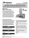
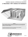
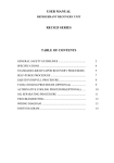
Part #459968
Tubular Centrifugal & Mixed Flow
®
Installation, Operation and Maintenance Manual
Please read and save these instructions. Read carefully before attempting to assemble, install, operate or maintain the
product described. Protect yourself and others by observing all safety information. Failure to comply with instructions
could result in personal injury and/or property damage! Retain instructions for future reference.
Model TCF
Tubular Centrifugal Inline Fan
Models QEI and QEID
Mixed Flow Inline Fan
General Safety Information
Only qualified personnel should install this fan.
Personnel should have a clear understanding of these
instructions and should be aware of general safety
precautions. Improper installation can result in electric
shock, possible injury due to coming in contact with
moving parts, as well as other potential hazards.
Other considerations may be required if high winds
or seismic activity are present. If more information
is needed, contact a licensed professional engineer
before moving forward.
DANGER
Always disconnect power before working on or near
a fan. Lock and tag the disconnect switch or breaker
to prevent accidental power up.
CAUTION
When servicing the fan, motor may be hot enough
to cause pain or injury. Allow motor to cool before
servicing.
CAUTION
Precaution should be taken in explosive
atmospheres.
1
Model TCF and Models QEI/QEID Centrifugal
1. Follow all local electrical and safety codes, as
well as the National Electrical Code (NEC) and the
National Fire Protection Agency (NFPA), where
applicable. Follow the Canadian Electric Code
(CEC) in Canada.
2. The rotation of the wheel is critical. It must be free
to rotate without striking or rubbing any stationary
objects.
3. Motor must be securely and adequately grounded.
4. Do not spin fan wheel faster than max cataloged
fan rpm. Adjustments to fan speed significantly
effects motor load. If the fan RPM is changed, the
motor current should be checked to make sure it is
not exceeding the motor nameplate amps.
5. Do not allow the power cable to kink or come in
contact with oil, grease, hot surfaces or chemicals.
Replace cord immediately if damaged.
6. Verify that the power source is compatible with the
equipment.
7. Never open access doors to a duct while the fan is
running.
Receiving
Upon receiving the product check to make sure all
items are accounted for by referencing the bill of
lading to ensure all items were received. Inspect
each crate for shipping damage before accepting
delivery. Notify the carrier if any damage is noticed.
The carrier will make notification on the delivery
receipt acknowledging any damage to the product.
All damage should be noted on all the copies of the
bill of lading which is countersigned by the delivering
carrier. A Carrier Inspection Report should be filled out
by the carrier upon arrival and the Traffic Department.
If damaged upon arrival, file claim with carrier. Any
physical damage to the unit after acceptance is not
the responsibility of Greenheck Fan Corporation.
Unpacking
Verify that all required parts and the correct quantity
of each item have been received. If any items are
missing report shortages to your local representative
to arrange for obtaining missing parts. Sometimes it
is not possible that all items for the unit be shipped
together due to availability of transportation and truck
space. Confirmation of shipment(s) must be limited to
only items on the bill of lading.
Handling
Fans are to be rigged and moved by the lifting
brackets provided or by the skid when a forklift is
used. Location of brackets varies by model and size.
Handle in such a manner as to keep from scratching
or chipping the coating. Damaged finish may reduce
the ability of the fan to resist corrosion.
Fans should never be lifted by the shaft, fan housing,
motor, belt guard, windband or accessories.
Storage
Fans are protected against damage during shipment.
If the unit cannot be installed and operated
immediately, precautions need to be taken to prevent
deterioration of the unit during storage. The user
assumes responsibility of the fan and accessories
while in storage. The manufacturer will not be
responsible for damage during storage. The following
suggestions are provided solely as a convenience to
the user.
INDOOR
The ideal environment for the storage of fans and
accessories is indoors, above grade, in a low humidity
atmosphere which is sealed to prevent the entry of
blowing dust, rain, or snow. Temperatures should
be evenly maintained between 30°F (-1°C) and
110°F (43°C) (wide temperature swings may cause
condensation and “sweating” of metal parts). All
accessories must be stored indoors in a clean, dry
atmosphere.
2
Model TCF and Models QEI/QEID Centrifugal
Remove any accumulations of dirt, water, ice or snow
and wipe dry before moving to indoor storage. To
avoid “sweating” of metal parts allow cold parts to
reach room temperature. To dry parts and packages
use a portable electric heater to get rid of any
moisture build up. Leave coverings loose to permit air
circulation and to allow for periodic inspection.
The unit should be stored at least 3½ inches (89 mm)
off the floor on wooden blocks covered with moisture
proof paper or polyethylene sheathing. Aisles between
parts and along all walls should be provided to permit
air circulation and space for inspection.
OUTDOOR
Roads or aisles for portable cranes and hauling
equipment are needed.
The fan should be placed on a level surface to prevent
water from leaking into the fan. The fan should be
elevated on an adequate number of wooden blocks so
that it is above water and snow levels and has enough
blocking to prevent it from settling into soft ground.
Locate parts far enough apart to permit air circulation,
sunlight, and space for periodic inspection. To
minimize water accumulation, place all fan parts on
blocking supports so that rain water will run off.
The use of a tarp to cover the unit will aid in keeping it
clean and dry. Avoid using a black plastic tarp as it will
promote condensation.
Fan wheels should be blocked to prevent spinning
caused by strong winds.
Inspection and Maintenance during
Storage
While in storage, inspect fans once per month. Keep a
record of inspection and maintenance performed.
If moisture or dirt accumulations are found on parts,
the source should be located and eliminated. At each
inspection, rotate the wheel by hand ten to fifteen
revolutions to distribute lubricant on motor. If paint
deterioration begins, consideration should be given
to touch-up or repainting. Fans with special coatings
may require special techniques for touch-up or repair.
Machined parts coated with rust preventive should
be restored to good condition promptly if signs of
rust occur. Immediately remove the original rust
preventive coating with petroleum solvent and clean
with lint-free cloths. Polish any remaining rust from
surface with crocus cloth or fine emery paper and oil.
Do not destroy the continuity of the surfaces. Wipe
clean thoroughly with Tectyl® 506 (Ashland Inc.) or
the equivalent. For hard to reach internal surfaces or
for occasional use, consider using Tectyl® 511M Rust
Preventive or WD-40® or the equivalent.
®
REMOVING FROM STORAGE
QEI/QEID Radial Gap
As fans are removed from storage to be installed
in their final location, they should be protected and
maintained in a similar fashion, until the fan equipment
goes into operation.
Adjust inlet cone position such that the radial gap
between the wheel cone and inlet cone is evenly
distributed around the wheel.
Prior to fully assembling and installing the fan and
system components, inspect the fan assembly to
make sure it is in working order.
If necessary, adjust wheel position by loosening the
wheel hub from the fan shaft so that a straight edge
held tight to the wheel cone just touches the inlet
cone. Refer to drawing below.
1. Check all fasteners, set screws, wheel, bearings,
drive, motor base and accessories for tightness.
QEI/QEID Alignment
Straight Edge
2. Rotate the fan wheel by hand and assure no parts
are rubbing. Access to the wheel is obtained
through an access panel located on the side of the
fan housing.
Wheel
Cone
3. Ensure proper wheel settings for radial gap and
alignment. See below.
1 Fan
Wheel
Dia.
Radial Gap, Overlap & Alignment
Efficient fan performance can be maintained by having
the correct radial gap, overlap and alignment. These
items should be checked before start-up and after the
fan has been in operation for 24 hours.
TCF Radial Gap
Radial gap is adjusted by loosening the inlet
cone bolts and centering the cone on the wheel.
If additional adjustment is required to maintain a
constant radial gap, loosening the bearing bolts and
centering wheel is acceptable
Overlap
as a secondary option.
TCF Overlap
Overlap is adjusted by
loosening the wheel hub from
the shaft and moving the
wheel to the desired position
along the shaft. The chart
shows the proper distance
between the wheel and
Radial
the inlet cone.
Gap
TCF Size
18
20
22
24
27
30
33
36
40
44
49
54
60
66
73
®
Dimension A (in.)
6 ⁄8
7
713⁄16
85⁄8
97⁄16
109⁄16
117⁄16
123⁄4
143⁄16
159⁄16
171⁄8
1813⁄16
2015⁄16
227⁄8
251⁄2
3
± ⁄8
±13⁄16
±13⁄16
±1⁄4
±1⁄4
±3⁄8
±3⁄8
±3⁄8
±3⁄8
±3⁄8
±1⁄2
±1⁄2
±1⁄2
±1⁄2
±1⁄2
1
Poor
Radial
Gap
Inlet Cone
Installation
Length of
Installations with poor inlet or discharge
Straight Duct
configurations may result in reduced fan performance.
Ducted Installations
Inlet Duct Turns – Installation of a duct turn or elbow
too close to the fan inlet reduces fan performance.
Restricted or unstable flow at the fan Good
inlet can cause
pre-rotation of incoming air or uneven loading of the
fan wheel, yielding large system losses and increased
sound levels. To achieve full fan performance, there
should be at least one fan wheel diameter between
the turn or elbow and the fan inlet.
Good
Poor
1 Fan
Wheel
Dia.
A
Turning
Vanes
Dimension A (mm)
86
178
198
219
240
268
291
324
360
395
435
478
532
581
648
±3
±5
±5
±6
±6
±10
±10
±10
1 Fan
Wheel
Dia.
±10
±10
±13
±13
±13
±13
±13
Discharge Duct
Turns – Fan performance
is reduced
Poor
Good
Poor
when duct turns are made immediately
off the fan
discharge. To achieve cataloged fan performance
there should be at least three equivalent duct
1 straight
Fan
diameters ofWheel
ductwork between the fan
Dia.
Poor
discharge and any duct turns.
Poor
Length of
Straight Duct
Good
Length of
Straight Duct
Good
Models TCF and Model QEI/QEID Centrifugal
3
Non-Ducted Installation
1 Fan
Wheel
Inlet Clearance – Installation of a fan with an openDia.
inlet too close to a wall or bulkhead will cause
reduced fan performance.
It is desirable to have a
1 Fan
minimum of one fan wheel
Wheel
Dia.
diameter between the fan
inlet and the wall.
Free Discharge – Free
or abrupt discharge
into a plenum results
in a reduction in fan
performance. The effect
of discharge static regain
is not realized, and
performance is reduced.
Unit Start-Up
Poor
DANGER
High voltage electrical input is needed for this
equipment. This work should be performed by a
qualified electrician.
Length of
Straight Duct
WARNING
Disconnect and secure to the “Off” position all
electrical power to the fan prior to inspection
or servicing. Failure to comply with this safety
Length of
precaution could result
in Duct
serious injury or death.
Straight
Duct Connections
It is highly recommended to use a flexible sleeve
connection instead of a rigid duct connection. This will
reduce vibration transmission through the ductwork.
Slip-Fit End Connection (QEI/QEID)
Directly attach the flexible sleeve to the duct and fan.
1 Fan
No additional parts are required.
Wheel
Dia.
Flexible Sleeve
Flexible Sleeve
Fan
Duct
Turning
Vanes
Fan
Duct
1 Fan
Wheel
Dia.
Flanged End Connection (TCF/QEI/QEID)
Good
Optional companion flanges Turning
are bolted to the fan to
Vanes
Flexible Sleeve
provide a slip-fit connection
for a flexible sleeve.
Flexible Sleeve
Good
Fan
Duct
Fan
Duct
1. Disconnect
and lock-out all power switches to
Good
fan.
2. Check all fasteners, set screws and locking
collars on the fan, wheel, bearings, drive, motor
base and accessories for tightness.
Good
3. Rotate
the fan wheel by hand and assure no parts
are rubbing.
4. Check for bearing alignment and lubrication.
5. Check the V-belt drive for proper alignment and
tension.
6. Check all guarding (if supplied) to ensure that it is
securely attached and not interfering with rotating
parts.
7. Check operation of variable inlet vanes or
discharge dampers (if supplied) for freedom of
movement.
8. Check all electrical connections for proper
attachment.
Poor
9. Check housing and ductwork, if accessible,
for obstructions and foreign material that may
damage the fan wheel.
10. Check for proper wheel rotation by momentarily
energizing
the fan. Rotation should correspond
Poor
to the rotation decal affixed to the unit (CCW
rotation is correct as viewed from the fan inlet).
Companion Flange
Companion Flange
Note: Flexible sleeve & attachment hardware not provided.
Mixed Flow
Centrifugal Airfoil
NOTE: One of the most frequently encountered
problems with centrifugal fans is motors which are
wired to run in the wrong direction. This is especially
true with 3-phase installations where the motor will
run in either direction, depending on how it has
been wired. To reverse rotation of a 3-phase motor,
interchange any two of the three electrical leads.
Single phase motors can be reversed by changing
internal connections as described on the motor label
or wiring diagram.
4
Model TCF and Models QEI/QEID Centrifugal
®
11. If the fan has inlet vanes, they should be partially
closed to reduce power requirements.
12. Fans with multi-speed motors should be checked
on low speed during initial start-up.
13. Ensure proper wheel location for radial gap,
overlap and alignment (see Radial Gap, Overlap
& Alignment section on page 3).
14. Grease may be forced out of the bearing seals
during initial start-up. This is a normal selfpurging feature of the bearing.
15. Check for unusual noise, vibration or overheating
of bearings. Refer to the Troubleshooting section
of this manual if a problem develops.
Vibration
Excessive vibration is the most frequent problem
experienced during initial start-up. Left unchecked,
excessive vibration can cause a multitude of
problems, including structural and/or component
failure.
The most common sources of vibration are:
Wheel unbalance
Drive pulley misalignment
Incorrect belt tension
Bearing misalignment
Mechanical looseness
Faulty belts
Drive component unbalance
Poor inlet/outlet conditions
Foundation stiffness
Many of these conditions can be discovered by careful
observation. Refer to the Troubleshooting section
of this manual for corrective actions. If observation
cannot locate the source of vibration, a qualified
technician using vibration analysis equipment should
be consulted. If the problem is wheel unbalance,
in‑place balancing can be done providing there is
access to the fan wheel. Any correction weights
added to the wheel should be welded to either the
wheel back (single-plane balance) or to the wheel
back and wheel cone (two-plane balance).
Maintenance
WARNING
Disconnect and secure to the “Off” position all
electrical power to the fan prior to inspection
or servicing. Failure to comply with this safety
precaution could result in serious injury or death.
Once the unit has been put into operation, a routine
maintenance schedule should be set up to accomplish
the following:
1. Lubrication of bearings and motor.
2. Variable inlet vanes should be checked for freedom
of operation and wear.
3. Wheel, housing, bolts and set screws on the entire
fan should be checked for tightness.
®
4. Any dirt accumulation on the wheel or in the
housing should be removed to prevent unbalance
and possible damage.
5. Isolation bases should be checked for freedom
of movement and the bolts for tightness. Springs
should be checked for breaks and fatigue. Rubber
isolators should be checked for deterioration.
6. Inspect fan impeller and housing looking for
fatigue, corrosion or wear.
WARNING
Changing the belts or drives can significantly
increase the amp draw of the motor. If changes
are made to the drives or belts, the amps must be
checked to assure no overamping.
V-Belt Drives
V-belt drives must be checked on a regular basis
for wear, tension, alignment and dirt accumulation.
Premature or frequent belt failures can be caused by
improper belt tension (either too loose or too tight)
or misaligned sheaves. Abnormally high belt tension
or drive misalignment will cause excessive bearing
loads and may result in failure of the fan and/or motor
bearings. Conversely, loose belts will cause squealing
on start-up, excessive belt flutter, slippage and
overheated sheaves. Either excessively loose or tight
belts may cause fan vibration.
When replacing V-belts on multiple groove drives,
all belts should be changed to provide uniform drive
loading. Do not pry belts on or off the sheave. Loosen
belt tension until belts can be removed by simply
lifting the belts off the sheaves. After replacing belts,
ensure that slack in each belt is on the same side of
the drive. Belt dressing should never be used.
Do not install new belts on worn sheaves. If the
sheaves have grooves worn in them, they must be
replaced before new belts are installed.
The proper tension for operating a V-belt drive is
the lowest tension at which the belts will not slip at
peak load conditions. Belts are adjusted by raising or
lowering the motor pivot plate. For initial tensioning,
the proper belt deflection half-way between sheave
centers is 1/64 of the belt span. For example, if the
belt span is 64 inches, the belt deflection should be
1 inch using moderate thumb pressure at mid-point
of the drive. Check belt tension two times during
the first 24 hours of operation and periodically
thereafter.
Deflection = Belt Span
64
Belt Span
Models TCF and Model QEI/QEID Centrifugal
5
V-Belt Replacement
Fan Bearing Lubrication
The V-belt drive components, when supplied by
Greenheck Fan Corporation, have been carefully
selected for this unit’s specific operating condition.
Changing V-belt drive components could result
in unsafe operating conditions which may cause
personal injury or failure of fan components.
The bearings for Greenheck fans are carefully
selected to match the maximum load and operating
conditions of the specific class, arrangement and
fan size. The instructions provided in this manual
and those provided by the bearing manufacturer will
minimize any bearing problems. Bearings are the
most critical moving part of the fan. Therefore, special
care is required when mounting them on the unit and
maintaining them.
1. Remove the protective coating from the end of the
fan shaft using mineral spirits or another similar
solvent. Check to ensure that the shaft is free of
nicks and burrs.
2. Slide sheaves on shafts. Do not drive sheaves on
as this may result in bearing damage.
3. Align fan and motor sheaves
with a straight-edge or string
and tighten.
4. Place belts over sheaves. Do
not pry or force belts, as this
could result in damage to the
cords in the belts.
5. Adjust the tension until the
Aligning sheaves
belts appear snug. Run the
with a straight edge
unit for a few minutes (refer to
unit start-up section) and allow the belts to “set”
properly.
6. With the fan off, adjust the belt tension by moving
the motor pivot plate. (Belts are adjusted by
raising or lowering the motor pivot plate). When in
operation, the tight side of the belts should be in
a straight line from sheave to sheave with a slight
bow on the slack side.
FAN
MOTOR
FAN
Motors
Motor maintenance is generally limited to cleaning
and lubrication. Cleaning should be limited to exterior
surfaces only. Removing dust and grease build-up on
the motor housing assists proper motor cooling.
CAUTION
Do not allow water or solvents to enter the motor or
bearings. Under no circumstances should motors or
bearings be sprayed with steam, water or solvents.
Greasing of motor bearings is only required when
fittings are provided. Many fractional motors are
permanently lubricated and require no further
lubrication. Motors supplied with grease fittings
should be greased in accordance with the
manufacturer’s recommendations. When motor
temperature does not exceed 104ºF (40ºC), the grease
should be replaced after 2000 hours of running time.
6
Model TCF and Models QEI/QEID Centrifugal
MOTOR
Refer to the following chart and the manufacturer’s
instructions for grease types and intervals for various
operating conditions. Never mix greases made with
different bases. This will cause a breakdown of the
grease and possible failure of the bearing.
Recommended Fan Bearing Lubrication Schedule (in Months*)
Fan
RPM
Bearing Bore
15
⁄2 - 1 1 ⁄8 - 1 ⁄2 1 ⁄8 - 17⁄8 -123⁄16
⁄16
1
1
1
5
27⁄16
-3
33⁄16
- 31⁄2
315⁄16
- 41⁄2
To 250
6
6
6
6
6
5
4
500
6
6
6
5
4
3
3
750
6
5
4
3
3
2
2
1000
6
4
3
2
2
1
1
1250
5
3
2
1
1
0.5
0.5
1500
5
2
1
1
0.5
0.5
0.25
2000
5
1
1
0.5
0.25
0.25
0.25
2500
4
0.5
0.5
0.25
0.25
0.25
3000
4
0.5
0.25
0.25
0.25
*Suggested initial greasing interval is based on 12 hour per
day operation and 150º F. maximum housing temperature.
For continuous (24 hour) operation, decrease greasing
interval by 50%.
• If possible, relubricate with grease while in operation
without endangering personnel.
• For ball bearings (operating) relubricate until clean
grease is seen purging at the seals. Be careful not to
unseat the seal by over lubricating.
• For ball bearings (idle) add 1-2 shots of grease up to 2
in. bore sizes, and 4-5 shots of grease above 2 in. bore
sizes with hand grease gun.
• For roller bearings, relubricate with 4 shots of grease up
to 2 in. bore size, 8 shots for 2-5 in. bore size, and 16
shots above 5 in. bore size with hand grease gun.
• Adjust lubrication frequency based on condition of
purged grease.
• A high quality lithium base grease conforming to NLGI
Grade 2 consistency, such as those listed below, should
be used.
Mobilith SHC 220
Texaco Multifak AFB2
Mobilith AW2
Texaco Premium RB
Shell Alvania #2
Exxon Unirex N2
WARNING
Lubricate bearings prior to periods of extended
shutdowns or storage and rotate shaft monthly to
aid in preventing corrosion. If the fan is stored more
than three months, the bearings should be purged
with new grease prior to start-up.
®
Fan Bearing Replacement
Replacement of bearings requires disassembly of internal components. For this procedure access must be
available to both the inlet and outlet ends. The following procedure assumes belts have already been loosened
and removed. (Belts are removed by adjusting the motor pivot plate).
Reinstall components in reverse order of removal. Reference the Radial Gap, Overlap & Alignment section to
ensure proper wheel installation.
Model TCF
Model QEI
1. Remove cover plate from drive chamber (outlet
side).
2. Unbolt and remove inlet cone (inlet side).
3. Loosen set screws at the wheel hub and remove
wheel (inlet side).
4. Unbolt both sets of bearings from support bars
(outlet side).
5. Remove shaft/bearing assembly (outlet side).
6. Replace bearings on drive shaft.
If the bearings cannot be removed from the shaft due
to corrosion or damage, the bearing plates can be
removed from the inner chamber. The shaft/bearing/
bearing plates can be removed as a complete
assembly from the fan inlet.
Housing
Inlet
Cone
Wheel
Shaft/Bearing
Assembly
Cover
Plate
1. Unbolt and remove inlet cone (inlet side).
2. Loosen set screws at the wheel hub and remove
wheel (inlet side).
3. Remove bolts from drive bearing plate (outlet side).
4. Remove bolts from wheel bearing plate (inlet side).
5. Pull shaft/bearing/bearing plate assembly out of
the fan housing (inlet side).
6. Replace bearings on shaft/bearing/bearing plate
assembly.
Inlet
Cone
®
Shaft/Bearing/
Bearing Plate Assembly
Wheel
Housing
Models TCF and Model QEI/QEID Centrifugal
7
Troubleshooting
Problem
Cause
Corrective Action
Wheel Rubbing Inlet
Adjust wheel and/or inlet cone. Tighten wheel hub or bearing collars
on shaft.
V-Belt Drive
Tighten sheaves on motor/fan shaft. Adjust belt tension. Align sheaves
properly (see page 6). Replace worn belts or sheaves.
Bearings
Replace defective bearing(s). Lubricate bearings. Tighten collars and
fasteners.
Wheel Unbalance
Clean all dirt off wheel. Check wheel balance, rebalance in-place if
necessary.
Fan
Check wheel for correct rotation. Increase fan speed.
Duct System
See pages 3 and 4.
Fan
Decrease fan speed.
Duct System
Resize ductwork. Access door, filters, grilles not installed.
Duct system has more or less
restriction than anticipated
Change obstructions in system. Use correction factor to adjust for
temperature/altitude. Resize ductwork. Clean filters/coils. Change fan
speed.
Fan
Check rotation of wheel.
Duct System
Resize ductwork. Check proper operation of face and bypass
dampers. Check filters and access doors.
Electrical Supply
Check fuses/circuit breakers. Check for switches turned off or
disconnected. Check for correct supply voltage.
Drive
Check for broken belts. Tighten loose pulleys.
Motor
Assure motor is correct horsepower and not tripping overload
protector.
Lubrication
Check for excessive or insufficient grease in the bearing.
Mechanical
Replace damaged bearing. Relieve excessive belt tension. Align
bearings. Check for bent shaft.
Belts
Adjust tightness of belts. Replacement belts should be a matched set.
System Unbalance
Check alignment of shaft, motor and pulleys. Adjustable pitch pulleys
with motors over 15 hp motors are especially prone to unbalance.
Check wheel balance, rebalance if necessary.
Excessive Noise
Volume Too Low
Volume Too High
Static Pressure Wrong
Excessive Power Consumption
High Horsepower
Fan Doesn’t Operate
Bearings Overheated
Excessive Vibration
Warranty
Greenheck warrants this equipment to be free from defects in material and workmanship for a period of one year from
the purchase date. Any units or parts which prove defective during the warranty period will be replaced at our option
when returned to our factory, transportation prepaid. Motors are warranted by the motor manufacturer for a period of
one year. Should motors furnished by Greenheck prove defective during this period, they should be returned to the
nearest authorized motor service station. Greenheck will not be responsible for any removal or installation costs.
As a result of our commitment to continuous improvement, Greenheck reserves the right to change specifications
without notice.
Greenheck Catalogs Model TCF and Models QEI/QEID
provide additional information describing the equipment, fan
performance, available accessories, and specification data.
AMCA Publication 410-96, Safety Practices for Users and
Installers of Industrial and Commercial Fans, provides
additional safety information. This publication can be
obtained from AMCA International, Inc. at www.amca.org.
®
Phone: (715) 359-6171 • Fax: (715) 355-2399 • E-mail: [email protected] • Website: www.greenheck.com
8
459968 • TCF and QEI/QEID, Rev. 3, July 2008
Copyright 2008 © Greenheck Fan Corporation