1
INSTRUCTIONS–PARTS LIST
308846
Rev. D
This manual contains important
warnings and information.
READ AND KEEP FOR REFERENCE.
First choice when
quality counts.t
INSTRUCTIONS
ACETAL HUSKYt 307, STAND MOUNT
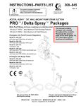
PROt/ Delta Sprayt Packages
Metal fluid fittings and hose couplings are stainless steel.
100 psi (0.7 MPa, 7 bar) Maximum Fluid Working Pressure
100 psi (0.7 MPa, 7 bar) Maximum Air Inlet Pressure
Packages with Fluid Pressure Regulators
Model No. 240367
with hoses and Delta Spray air spray gun
This manual contains
changes not included
throughout the contents.
Please see the second
page of this book (page 1A)
for a description of the
revisions and additions.
Model No. 240368
with hoses and Delta Spray HVLP gun
Model No. 240369
with hoses and PRO 3500sc electrostatic gun
Model No. 240370
with hoses and PRO 4500sc electrostatic gun
Model No. 240371
no hoses or gun
Packages with Surge Tanks
Model No. 240379
with hoses and Delta Spray air spray gun
Model No. 240380
with hoses and Delta Spray HVLP gun
Model No. 240381
no hoses or gun
8115A
This gun and hose for Delta Spray Air Spray
packages and Delta Spray HVLP packages
GRACO INC.
P.O. BOX 1441
This gun and hose for PRO 3500sc
Electrostatic packages
MINNEAPOLIS, MN
ECOPYRIGHT 1998, GRACO INC.
Graco Inc. is registered to I.S. EN ISO 9001
55440–1441
Instruction Manual – Parts List Changes
This page contains a summary of changes or additions that do not appear in the contents
of the manual.
Improve pressure control instructions (Graco ref. V6557).
Change 30psi HVLP fluid regulator and gauge to 60psi (Graco ref. V6808).
308846
1A
Notes
308846
1B
Table of Contents
Warnings . . . . . . . . . . . . . . . . . . . . . . . . . . . . . . . . . 2
Setup . . . . . . . . . . . . . . . . . . . . . . . . . . . . . . . . . . . . 4
Operation . . . . . . . . . . . . . . . . . . . . . . . . . . . . . . . . 6
Maintenance . . . . . . . . . . . . . . . . . . . . . . . . . . . . . . 9
Parts List and Parts Drawing
240367 to 240371 . . . . . . . . . . . . . . . . . . . . 10
240379 and 240381 . . . . . . . . . . . . . . . . . . . 12
Fluid Filter Kit 240440 . . . . . . . . . . . . . . . . . . . . . 14
Suction Tube Kit 240465 . . . . . . . . . . . . . . . . . . 15
Technical Data . . . . . . . . . . . . . . . . . . . . . . . . . . . 16
Dimensions . . . . . . . . . . . . . . . . . . . . . . . . . . . . . . 17
Graco Standard Warranty . . . . . . . . . . . . . . . . . 20
Graco Phone Number . . . . . . . . . . . . . . . . . . . . . 20
Symbols
Warning Symbol
WARNING
WARNING
This symbol alerts you to the possibility of serious
injury or death if you do not follow the instructions.
Caution Symbol
CAUTION
This symbol alerts you to the possibility of damage to
or destruction of equipment if you do not follow the
corresponding instructions.
WARNING
PRESSURIZED FLUID HAZARD
Spray from the gun, hose leaks, or ruptured components can splash fluid in the eyes or on the skin
and cause serious injury.
D Do not stop or deflect fluid leaks with your hand, glove, or rag.
D Follow the Pressure Relief Procedure on page 6 before cleaning, checking, or servicing the
equipment.
D Tighten all fluid connections before each use.
D Check the hoses, tubes, and couplings daily. Replace parts immediately if worn, damaged, or
loose. Permanently coupled hoses cannot be repaired.
FIRE AND EXPLOSION HAZARD
Improper grounding, poor air ventilation, open flames, or sparks can cause a hazardous condition and
result in fire or explosion and serious injury.
D Ground the equipment, personnel in or close to the spray area, the object being sprayed, and all
other electrically conductive objects in the spray area. See Grounding on page 5.
D If there is any static sparking while using the equipment, stop spraying immediately. Identify and
correct the problem.
D Provide fresh air ventilation to avoid the buildup of flammable vapors from the solvent or the fluid
being sprayed.
D Do not smoke in the spray area.
D Extinguish all open flames or pilot lights in the spray area.
D Do not turn on or off any light switch in the spray area.
D Electrically disconnect all equipment in the spray area.
D Keep the spray area free of debris, including solvent, rags, and gasoline.
D Do not operate a gasoline engine in the spray area.
2
308846
WARNING
EQUIPMENT MISUSE HAZARD
INSTRUCTIONS
Equipment misuse can cause the equipment to rupture, malfunction, or start unexpectedly and result
in a serious injury.
D This equipment is for professional use only.
D Read all the instruction manuals, tags, and labels before operating the equipment.
D Use the equipment only for its intended purpose. If you are uncertain about usage, call your Graco
distributor.
D Do not alter or modify this equipment. Use only genuine Graco parts and accessories.
D Check the equipment daily. Repair or replace worn or damaged parts immediately.
D Do not exceed the maximum working pressure of the lowest rated system component. This package has a 100 psi (0.7 MPa, 7 bar) maximum working pressure.
D Use fluids that are compatible with the equipment wetted parts. See the Technical Data section of
all the equipment manuals. Read the fluid manufacturer’s warnings.
D Route the hoses away from traffic areas, sharp edges, moving parts, and hot surfaces. Do not
expose Graco hoses to temperatures above 180_F (82_C) or below –40_F (–40_C).
D Do not use the hoses to pull equipment.
D Do not move pressurized equipment.
D Wear hearing protection when operating this equipment.
D Comply with all applicable local, state, and national fire, electrical, and other safety regulations.
TOXIC FLUID HAZARD
Hazardous fluids or toxic fumes can cause a serious injury or death if splashed in the eyes or on the
skin, swallowed, or inhaled.
D Know the specific hazards of the fluid you are using. Read the fluid manufacturer’s warnings.
D Store hazardous fluid in an approved container. Dispose of the hazardous fluid according to all
local, state, and national guidelines.
D Wear appropriate protective clothing, gloves, eyewear, and respirator.
D If the pump diaphragm fails, hazardous fluid may be exhausted along with the air.
308846
3
Setup
CAUTION
Preparing the Operator
This equipment is compatible with most water-based
materials. See the wetted parts in the Technical
Data section and your fluid and solvent
manufacturer’s compatibility information.
Anybody who operates this system should be trained
in the safe, efficient operation of all system
components. At a minimum, all operators should
thoroughly read the safety, setup, and operation
sections of this manual.
Do not use acid catalyzed materials; they are incompatible with the acetal used in this pump.
Preparing the Site
WARNING
TOXIC FLUID HAZARD
Hazardous fluid or toxic fumes can
cause serious injury or death if splashed
in the eyes or on the skin, inhaled, or
swallowed.
D Read TOXIC FLUID HAZARD on page 3.
D Use fluids and solvents that are compatible with
the equipment wetted parts. Refer to the Technical Data section of all equipment manuals.
Read the fluid and solvent manufacturer’s
warnings.
General Information
D Always use Genuine Graco Parts and Accessories,
available from your Graco distributor. See the
Product Data Sheet for this package, Form No.
305898. If you supply your own accessories, be
sure they are adequately sized and pressure rated
for your system.
D Reference numbers and letters in parentheses refer
to the callouts in the figures and the parts lists on
pages 10 and 12.
4
308846
D Use a compressor capable of delivering 40 cfm
(1.12 m3) and a minimum of 80 psi (552 kPa,
5.4 bar) for efficient operation.
D Clear obstacles and debris that could cause an
unsafe operating environment.
D Run a 1/2 in. I.D. air line from your compressed air
supply to the pump location. Be sure the air is dry
and filtered.
D When the bleed-type master air valve (K) is closed
and the pump air regulator is opened, it relieves all
air pressure to the system components.
D Ventilate the spray booth.
WARNING
To prevent hazardous concentrations of toxic
and/or flammable vapors, spray only in a properly
ventilated spray booth. Never operate the spray
gun unless ventilation fans are operating.
Check and follow all of the national, state, and local
codes regarding air exhaust velocity requirements.
Setup
Hose Connections
This package is shipped with the hoses connected.
Before you disconnect any hoses, make a note of the
proper connections.
Flush Pump Before First Use
The pump was tested in water. If the test solution
could contaminate the fluid you are pumping, flush the
pump thoroughly with a compatible solvent. See
Flushing the System on page 8.
Grounding
WARNING
To reduce the risk of static sparking, the entire
system must be grounded. Check your local
electrical code for detailed grounding instructions
for your area and type of equipment. Ground all of
this equipment. Also read FIRE AND EXPLOSION
HAZARD on page 2.
D Pump: One end of the ground wire is already
connected to the pump grounding strip. Connect
the clamp end of the ground wire to a true earth
ground.
D Air compressor: Follow the manufacturer’s
recommendations.
D Object being sprayed: Follow the local code.
D Fluid supply container: Follow the local code.
D All solvent pails used when flushing: Follow the
local code. Use only metal pails, which are
conductive. Do not place the pail on a
non-conductive surface, such as paper or
cardboard, which interrupts the grounding
continuity.
D Systems with PRO 3500sc and PRO 4500sc
electrostatic gun: Make sure you read all of the
grounding instructions and warnings in your gun
instruction manual.
308846
5
Operation
Using the Gun
See the gun instruction manual for gun operation,
care, flushing, cleaning, and technical data. Read the
entire gun manual before operating the sprayer.
Pressure Relief Procedure
See Fig. 1
WARNING
The system remains pressurized until pressure is
manually relieved. To reduce the risk of serious
injury from pressurized fluid, accidental spray from
the gun, or splashing of any fluid, follow this procedure whenever you
D
D
D
D
Stop spraying
Are instructed to relieve pressure
Check or service any system equipment
Install, clean, or change spray nozzles
3. Slowly open the gun air regulator (F), and pull the
gun trigger just enough to open only the air valve
in the gun. With the gun air triggered, set the gun
air pressure to 60 psi (413 kPa, 4 bar).
NOTE: Gun air pressure higher than 60 psi (413
kPa, 4 bar) will cause excessive overspray and
lowered efficiency.
4. If your system has a fluid pressure regulator (G),
fully trigger the gun, and fine tune the fluid
pressure to obtain the desired atomization.
Systems with Fluid Pressure Regulator
See Fig. 1
With the fluid pressure regulator (G), you can control
fluid pressure from the pump to the gun. For an
accurate setting, adjust the fluid regulator only when
the gun is triggered and fluid is flowing through the
regulator. Be sure the jam nut under the T–handle (G)
does not interfere with your adjustments. Tighten the
jam nut to lock in the setting, if desired.
1. Turn off the air supply to the pump.
2. Be sure the pump air regulator is open by turning
the knob (E) clockwise several turns.
3. Open the bleed-type master air valve (K) to relieve
pump air pressure.
4. Trigger the gun (B) to relieve fluid pressure in the
hoses.
5. Open the recirculating valve (J) to relieve any fluid
pressure trapped in the system.
Adjusting Pump and Gun Air Regulators
See Fig. 1
NOTE: The pump air regulator knob (E) and gun air
regulator knob (F) have a locking feature. To unlock
the knobs, pull out on them. You will feel them click
out. To lock them at the desired setting, push them
back into the locked position.
Always adjust the pump air regulator (E) and gun air
regulator (F) slowly to prevent surging during startup.
Turn the knobs clockwise to increase pressure, and
counterclockwise to decrease air pressure.
1. Slowly adjust the pump air regulator (E), to set air
pressure to approximately 60 psi (413 kPa, 4 bar).
2. If your system has a fluid pressure regulator, turn
the fluid pressure regulator handle (G) to adjust
the fluid pressure to 40 to 60 psi ( 276 to 413 kPa,
2.8 to 4 bar).
6
308846
1. To open the fluid regulator, which allows fluid to
flow, turn the T-hand clockwise.
2. To close the fluid regulator, which restricts or shuts
off the fluid flow, turn the T-handle
counterclockwise.
Systems with Surge Tank
See Parts Drawing on page 13
In systems with a surge tank (30), the fluid pressure is
the same as the air pressure applied to the pump
(pump has 1:1 ratio of fluid to air). Adjust the fluid
pressure as required with the pump air regulator (E).
The surge tank filter screen may require periodic
cleaning. First, relieve the pressure. Unscrew the
surge tank cover from its base, and remove the filter
screen. Clean the screen with a compatible solvent,
and reinstall it in the surge tank. Make sure you
reinstall the cover with a firm hand torque to ensure a
good seal.
WARNING
To reduce the risk of serious injury whenever you
are instructed to relieve pressure, always follow the
Pressure Relief Procedure on page 6.
NOTE: The pump requires approximately 15 to 20 psi
(103 to 138 kPa, 1 to 1.4 bar)to function. This is the
lowest fluid pressure available. If lower fluid flow is
required, a smaller fluid tip may be required on the
spray device.
Operation
Priming the System See Fig. 1
1. Close the gun air regulator (F).
2. If your system has a fluid pressure regulator (G),
close it.
6. Slowly open the gun air regulator (F), and pull the
gun trigger just enough to open only the air valve
in the gun. With the gun air triggered, set the gun
air pressure to 60 psi (413 kPa, 4 bar).
7. Hold the gun against and aimed into a grounded
metal waste pail, and fully trigger the gun. If your
system has a fluid pressure regulator (G), slowly
open it.
3. Open the recirculating valve (J).
4. Open the bleed-type master air valve (K).
The gun emits air until the fluid arrives. When fluid
flows freely, release the gun trigger.
5. Slowly set the pump air regulator (E) pressure to
20 to 30 psi (140 to 210 kPa, 1.4 to 2.1 bar). The
pump cycles quickly, then it slows down when it is
primed. When it is primed, close the recirculating
valve (J); the pump will stall against the pressure.
If the pump does not start, reopen the recirculating
valve for 30 seconds, then close it. Set the pump
air pressure to 40 psi (280 kPa, 2.8 bar).
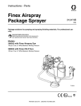
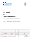
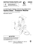
KEY
B
C
D
A
B
C
D
E
F
G
H
J
K
L
M
N
Husky 307 pump
Gun
Gun fluid hose
Gun air hose
Pump air regulator
Gun air regulator
Fluid pressure regulator
Pump ground wire
Recirculating valve
Bleed-type master air valve
Suction tube and return tube
Front shield assembly
Back shield
Delta Spray
regulated Air Spray package or
regulated HVLP package shown
G
K
F
J
N
M
D
L
C
E
A
H
8116A
Fig. 1
308846
7
Operation
Using the Recirculation Feature
See Fig. 1
3. Place the suction tube into a grounded metal pail
of compatible solvent.
The recirculation tube drains unused fluid back into the
fluid container, ensuring an even flow at the gun.
Recirculation also provides gentle fluid agitation. To
recirculate fluid, open the recirculation valve (J) while
you are spraying. To stop recirculation, close the valve.
4. Make sure the air regulators (E and F) and
bleed-type master air valve (K) are closed. Open
the recirculating valve (J).
When to Shut Down the System
5. Open the bleed-type master air valve (K).
Shut down the system at the end of the work shift and
before checking, adjusting, cleaning, or repairing the
system. Always relieve the pressure.
WARNING
To reduce the risk of serious injury whenever you
are instructed to relieve pressure, always follow the
Pressure Relief Procedure on page 6.
NOTE: The gun air regulator (F) always stays
closed during flushing.
6. Slowly open the pump air regulator (E) until the
pump starts. When fluid is flowing through the
recirculating valve (J), close the valve. The pump
will stall against pressure.
7. Hold the gun against a grounded metal waste pail,
and fully trigger the gun. If your system has a fluid
pressure regulator (G), slowly open it until the fluid
flows smoothly.
8. When solvent appears, release the gun trigger.
Flushing the System
Flush the system at the following times:
D Before the first-time use
D When changing colors
D Before fluid can dry or settle out in a dormant
system.
D Before storing the system
Flush the system as follows (See Fig. 1):
1. Relieve the pressure.
WARNING
To reduce the risk of serious injury whenever you
are instructed to relieve pressure, always follow the
Pressure Relief Procedure on page 6.
2. Remove the gun air cap before flushing, and clean
it separately.
8
308846
9. For a first-time flush: trigger the gun and flush with
solvent for 30 seconds.
For flushing after spraying fluid: trigger the gun
and flush with solvent until the system is
thoroughly cleaned. Open the recirculating valve
(J) slightly to clean the recirculation tube. Then
close it.
10. Repeat the procedure with clean solvent, if
needed.
11. Lift the fluid intake tube from the fluid supply, and
trigger the gun and run the pump until air comes
from the gun.
12. Relieve the pressure.
The system is now ready to be stored or primed with
another fluid. See Priming the System on page 7.
Maintenance
See the separate component instruction manuals for individual component maintenance procedures.
Access to some system components requires that you remove the shields. The following steps are for shield
removal. Shield replacement is the reverse of these steps, so make sure you take notes on the proper hose
connections. Depending on your system, see the Parts Drawings on pages 11 and 13 for number call-outs.
You cannot remove the front shield assembly while the pump and shields are mounted on the stand; thus, before
you can remove the front shield assembly (1) or the back shield (25), you must do the following steps:
1. Disconnect the gun air hose from the gun air regulator.
2. Disconnect the gun fluid hose from the fluid pressure regulator nipple (28) or surge tank nipple (40).
3. Remove the screws (32), nuts (23), and washer (22) from the mounting bracket (45).
4. Lift the entire system from the stand (41)
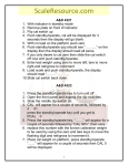
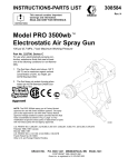
Front Shield Assembly (1)
Back Shield (25)
1. Disconnect the pump air hose from the pump air
regulator.
1. Disconnect the hose (18) that runs from the fluid
pressure regulator (40) or surge tank (30) to the
fitting on the pump outlet pipe tee (5).
2. Loosen, but do not remove, the two front pump
foot screws (24).
2. Loosen, but do not remove, the two top shield
screws (32).
3. Loosen, but do not remove, the two top shield
screws (32).
4. If your system has a fluid pressure regulator (40),
make sure the T–handle is horizontal.
5. Pull the front shield assembly free of the system.
1g
1c
1a
1f
1d
4. Pull the back shield free of the system. The fluid
pressure regulator (40) or surge tank (30) stays
mounted to the back shield.
Gauge Lense Covers
Clear, stick-on/peel-off lense covers are available for
the gauges. These covers protect the gauge lenses
from spray. When they get too dirty to read the
gauges, they can be peeled off, discarded, and
replaced.
1e
gun air
regulator
3. Loosen, but do not remove, the two back pump
foot screws (24).
NOTE: Several of these lense covers can be stacked
on the lense, and the gauge will still be clearly legible.
Then, as each lense cover gets dirty, only that one
layer will need to be peeled off.
1b 1h
pump air
regulator
Order as follows:
240441
for 2.5-inch gauges; package of 25
sheets, 12 lense covers to a sheet
240442
for 2-inch gauges; package of 25
sheets, 12 lense covers to a sheet
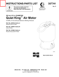
Front Shield Assembly Orderable Parts
Ref.
No.
Part No.
Description
1a
1b
192995
111804
1c
1d
1e
1f
1g
1h
160430
114362
159840
188077
114369
114370
SHIELD, front
REGULATOR, air
See instruction manual 308167
GAUGE, pressure
VALVE, ball
ADAPTER
NIPPLE
FITTING, tube
FITTING, tube
Fig. 2
Qty.
1
2
2
1
2
1
1
1
8263A
308846
9
Parts List
Stand-Mount Packages with Fluid Pressure Regulators
Model
Model
Model
Model
Model
No. 240367,
No. 240368,
No. 240369,
No. 240370,
No. 240371,
Ref.
No.
Part No.
1
240210
Delta Spray air spray package
Delta Spray HVLP package
PRO 3500sc electrostatic package
PRO 4500sc electrostatic package
no hoses or gun
Description
Qty.
SHIELD ASSY, front
Ref.
No.
Part No.
Description
38
239542
GUN, Delta Spray, air spray
Contains 1a to 1h, shown in Fig. 2 on
page 9
1
4
5
6
7
8
9
10
12
111917
113718
113222
114363
111811
114370
112903
D31331
NIPPLE; Nylon
TEE, pipe
CONNECTOR, male
VALVE, ball; sst
CONNECTOR, male
FITTING, tube, quick-connect
NUT, hex
PUMP, Husky 307
Model 240367
See instruction manual 308742
2
1
1
1
1
1
1
1
WASHER, lock
1
HOSE; Nylon
10 in.
TUBE; Nylon
11.5 in.
TUBE; PTFE R
10 in.
LABEL, warning
1
STRAP, tie, wire
3
WASHER, spring lock
6
NUT, hex
6
SCREW, cap, hex head
4
SHIELD, back
1
LUG, grounding
1
ELBOW, street
1
NIPPLE
1
HANDLE, shield
1
WASHER, flat
2
SCREW
2
SCREW, cap, hex head
4
FITTING, tube, quick-connect
1
LABEL, product
Models 240367, 240368, and 240371 1
LABEL, product
Models 240369 and 240370
1
GROUND WIRE & CLAMP ASSY 1
239561
222300
112899
054175
054139
054188
189220
103473
104123
102025
100021
192996
104029
113521
189436
192994
112789
100014
100333
114369
193251
193252
37
238909
240421
240425
HOSE ASSY, PRO gun;
25 ft (7.6 m) Models 240369 and
236449
REGULATOR, fluid pressure;
240370
0–30 psi (0–207 kPa, 0–2 bar)
Model 240368
See instruction manual 308325
236450
308846
1
1
1
REGULATOR, fluid pressure;
0–100 psi (0–0.6 MPa, 0–7 bar)
Models 240367 and 240369 to 240371
See instruction manual 308325
1
41
42
43
44
45
46
47
49
218743
108175
109534
111864
188169
054139
054175
240464
STAND, pump
1
PLUG
4
STRAINER, suction line
1
CONNECTOR, male
2
BRACKET
1
TUBE, suction
30 in.
TUBE, recirculation
32 in.
WIRE, ground, see Note in drawing.
PRO packages
Y Extra Warning labels are available for free.
10
1
HOSE ASSY, air spray/HVLP;
25 ft (7.6 m) Models 240367 and
240368
40
1
GUN, PRO 4500sc, electrostatic
Model 240370
See instruction manual 308131
39
1
GUN, PRO 3500sc, electrostatic
Model 240369
See instruction manual 307912
224200
1
GUN, Delta Spray, HVLP
Model 240368
See instruction manual 308741
See instruction manual 308553
13
16
17
18
19Y
21
22
23
24
25
26
27
28
29
30
31
32
33
34
Qty.
1
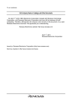
Parts Drawing
Stand-Mount Packages with Fluid Pressure Regulators
Model
Model
Model
Model
Model
No. 240367,
No. 240368,
No. 240369,
No. 240370,
No. 240371,
Delta Spray air spray package
Delta Spray HVLP package
PRO 3500sc electrostatic package
PRO 4500sc electrostatic package
no hoses or gun
Grounding Detail
26
29
32
37
27
18
40
13
10
30
19
1
17
25
12
24
18
9
34
31
28
16
6
17
4
16
5
33
4
44
7
45
24
8
32
22,
23
41
22
23
46
21
47
49
Note: For PRO packages only, terminal
end of ground wire (49) is assembled
between nut and lockwasher on handle
of recirculation valve (7). Bare end of
ground wire is assembled to grounding
lug (26) on pump (42).
44
38
42
43
38
222300
shown
39
39
8047A
308846
11
Parts List
Stand-Mount Packages with Surge Tanks
Model No. 240379, Delta Spray air spray package
Model No. 240380, Delta Spray HVLP package
Model No. 240381, no hoses or gun
Ref.
No.
Part No.
1
240210
Description
Qty.
SHIELD ASSY, front
Contains 1a to 1h, shown in Fig. 2 on
page 9
1
3
4
5
7
8
9
10
12
054139
111917
113718
114363
111811
114370
112903
D31331
13
16
17
18
19Y
21
22
23
24
25
26
112899
054175
054139
054188
189220
103473
104123
102025
100021
192996
104029
12
308846
TUBE, suction
30 in.
NIPPLE; Nylon
2
TEE, pipe
1
VALVE, ball; sst
1
CONNECTOR, male
1
FITTING, tube, quick-connect
1
NUT, hex
1
PUMP, Husky 307
See instruction manual 308553
1
WASHER, lock
1
HOSE; Nylon
10 in.
TUBE; Nylon
11.5 in.
TUBE; PTFE R
10 in.
LABEL, warning
1
STRAP, tie, wire
3
WASHER, spring lock
6
NUT, hex
6
SCREW, cap, hex head
4
SHIELD, back
1
LUG, grounding
1
Ref.
No.
Part No.
Description
27
28
29
30
31
32
33
34
37
38
114456
054175
192994
111911
106285
100333
114369
193253
238909
239542
FITTING, elbow, male
2
TUBE, recirculation
32 in.
HANDLE, shield
1
STRAINER, line
1
BOLT, “U”
2
SCREW, cap, hex head
4
FITTING, tube, quick-connect
1
LABEL, product
1
GROUND WIRE & CLAMP ASSY 1
GUN, Delta Spray, air spray;
25 ft (7.6 m) Model 240379
See instruction manual 308742
1
GUN, Delta Spray, HVLP;
25 ft (7.6 m) Model 240380
See instruction manual 308741
1
HOSE ASSY, air spray/HVLP
1
NIPPLE
1
STAND, pump
1
PLUG
4
STRAINER, suction line
1
CONNECTOR, male
2
BRACKET
1
239561
39
40
41
42
43
44
45
240421
188089
218743
108175
109534
111864
188169
Y Extra Warning labels are available for free.
Qty.
Parts Drawing
Stand-Mount Packages with Surge Tanks
Model No. 240379, Delta Spray air spray package
Model No. 240380, Delta Spray HVLP package
Model No. 240381, no hoses or gun
Grounding Detail
31
26
37
30
40
27
18
29
32
13
10
17
32
19
25
12
1
18
24
9
34
16
27
17
4
16
5
4
33
44
7
45
24
8
32
41
22,
23
22
23
28
3
44
42
21
38
43
39
8048A
308846
13
Accessory Fluid Filter Kit
Fluid Filter Kit 240440
Ref.
No.
Part No.
Description
101
102
103
104
105
114361
113322
054188
113534
111917
FILTER, fluid
CONNECTOR, male
TUBE; PTFE;R3/8” O.D.
ELBOW, male x female
NIPPLE; Nylon
Qty.
1
1
8 in.
2
1
The Fluid Filter Kit, listed above, can be installed to
filter fluid drawn by the suction tube after it comes out
of the pump. Install the Fluid Filter Kit as follows (see
Fig. 3):
{
To avoid sharp bends in the tube, you may have to cut
it to a shorter length.
}
Apply Graco Thread Sealer, or LoctiteR 567, or equivalent to male threads.
Y For initial installation, make sure the dome is firmly
hand tightened onto the filter body. Do not use a
tool. During subsequent service, hand tighten
more firmly to prevent drips.
1. Apply thread sealant (specified in Fig. 3) to all
male threads in this kit.
27
103{
2. Remove the male connector (6) and the PTFE R
tube (18) that connect to the top of the tee (5).
See the Parts drawing on page .
103}
3. Thread the nipple (105) into the female threads of
the elbow (104).
102}
4. Thread the nipple (105), with the elbow (104)
attached to it, into the tee (5).
101Y
104}
5. Thread the fluid filter (101) onto the male threads
of the elbow (104).
105}
6. Thread the male connector (102) into the fluid filter
(101).
5
7. Turn the fluid filter/male connector assembly
towards the elbow (27). This makes connecting
the tube (103) in step 8 easier.
8. Cut the PTFERtube (103) to the proper length,
and install it to run from the male connector (102)
to the elbow (27).
14
308846
Fig. 3
8114A
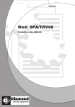
Accessory Suction Tube Kit
Suction Tube Kit 240465
}
Ref.
No.
Part No.
Description
201
202
203
204
232692
193411
193459
103473
KIT ASSEMBLY, suction tube
NIPPLE
TUBE, recirculation
TIE, wire
Qty.
Apply Graco Thread Sealer, or LoctiteR 567, or equivalent to threads.
1
1
1
5
The Suction Kit, listed above, can be installed for
drawing fluid from a container that is not directly under
the unit. Install the Suction Kit as follows (see Fig. 4):
202}
1. Remove the following parts from the stand unit:
recirculation tube (28), suction tube (3), male
connector (44), and suction line strainer (43). See
the Parts Drawing on page 13.
2. Apply thread sealant (specified in Fig. 4) to the
threads of the nipple (202).
201
3. Thread the nipple (202) into the pump inlet.
4. Thread the fitting of the suction tube assembly
(201) onto the nipple (202).
5. Install the new, longer recirculation tube (203) in
place of the old one.
203
204
8172A
Fig. 4
6. Bundle the new suction tube (201) and
recirculation tube (203) with the wire ties (204).
7. Route the new tubes into the remote fluid
container.
308846
15
Technical Data
Category
Data
Maximum fluid working pressure
100 psi (0.7 MPa, 7 bar)
Maximum incoming air pressure
100 psi (0.7 MPa, 7 bar)
Maximum operating temperature
120_ F (49_ C)
Gun
See separate gun instruction manual.
Pump
See separate pump instruction manual.
Fluid pressure regulator
See separate fluid pressure regulator instruction manual.
Air pressure regulators
See separate air pressure regulator instruction manual.
Wetted parts: fluid hoses for Delta guns
nylon, stainless steel
Wetted parts: fluid hoses for PRO guns
nylon, nickel-chrome plate
Wetted parts: other fluid hoses and tubing
nylon, PTFE R
Wetted parts: fluid fittings
nylon, acetal, 304/316 stainless steel
Weight (without hoses or gun):
packages with fluid pressure regulator
Approx. 30 lb (14 kg)
packages with surge tank
Approx. 28 lb (12.5)
Sound data:
Sound power level*
at 70 psi 0.48 MPa, 4.8 bar) and 115 cpm
68 dB(A)
Sound pressure level
at 70 psi 0.48 MPa, 4.8 bar) and 115 cpm
81.5 dB(A)
* Sound power level was measured per ISO Standard 3744.
TeflonR is a registered trademark of the DuPont Corporation.
16
308846
Dimensions
34.0 in.
(864 mm)
17.5 in.
(445 mm)
16.5 in.
(419 mm)
8171A
308846
17
Notes
18
308846
Notes
308846
19
Manual Change Summary
This manual went from Rev. A to Rev. B to make the following changes:
D Model No. 240371 (regulated packages with no hoses or gun) and Model No. 240381 (surge tank packages with
no hoses or gun) are added. See the front cover and the Parts Lists on pages 10 and 12.
D Part No. changes are made in the Parts Lists on pages 10 and 12: The pump foot screws (Ref No. 24) are
changed from 104119 to 100021.
Graco Standard Warranty
Graco warrants all equipment manufactured by Graco and bearing its name to be free from defects in material and workmanship on the
date of sale by an authorized Graco distributor to the original purchaser for use. With the exception of any special, extended, or limited
warranty published by Graco, Graco will, for a period of twelve months from the date of sale, repair or replace any part of the equipment
determined by Graco to be defective. This warranty applies only when the equipment is installed, operated and maintained in
accordance with Graco’s written recommendations.
This warranty does not cover, and Graco shall not be liable for general wear and tear, or any malfunction, damage or wear caused by
faulty installation, misapplication, abrasion, corrosion, inadequate or improper maintenance, negligence, accident, tampering, or
substitution of non-Graco component parts. Nor shall Graco be liable for malfunction, damage or wear caused by the incompatibility of
Graco equipment with structures, accessories, equipment or materials not supplied by Graco, or the improper design, manufacture,
installation, operation or maintenance of structures, accessories, equipment or materials not supplied by Graco.
This warranty is conditioned upon the prepaid return of the equipment claimed to be defective to an authorized Graco distributor for
verification of the claimed defect. If the claimed defect is verified, Graco will repair or replace free of charge any defective parts. The
equipment will be returned to the original purchaser transportation prepaid. If inspection of the equipment does not disclose any defect
in material or workmanship, repairs will be made at a reasonable charge, which charges may include the costs of parts, labor, and
transportation.
THIS WARRANTY IS EXCLUSIVE, AND IS IN LIEU OF ANY OTHER WARRANTIES, EXPRESS OR IMPLIED, INCLUDING BUT
NOT LIMITED TO WARRANTY OF MERCHANTABILITY OR WARRANTY OF FITNESS FOR A PARTICULAR PURPOSE.
Graco’s sole obligation and buyer’s sole remedy for any breach of warranty shall be as set forth above. The buyer agrees that no other
remedy (including, but not limited to, incidental or consequential damages for lost profits, lost sales, injury to person or property, or any
other incidental or consequential loss) shall be available. Any action for breach of warranty must be brought within two (2) years of the
date of sale.
Graco makes no warranty, and disclaims all implied warranties of merchantability and fitness for a particular purpose in connection
with accessories, equipment, materials or components sold but not manufactured by Graco. These items sold, but not manufactured
by Graco (such as electric motors, switches, hose, etc.), are subject to the warranty, if any, of their manufacturer. Graco will provide
purchaser with reasonable assistance in making any claim for breach of these warranties.
In no event will Graco be liable for indirect, incidental, special or consequential damages resulting from Graco supplying equipment
hereunder, or the furnishing, performance, or use of any products or other goods sold hereto, whether due to a breach of contract,
breach of warranty, the negligence of Graco, or otherwise.
FOR GRACO CANADA CUSTOMERS
The parties acknowledge that they have required that the present document, as well as all documents, notices and legal proceedings
entered into, given or instituted pursuant hereto or relating directly or indirectly hereto, be drawn up in English. Les parties
reconnaissent avoir convenu que la rédaction du présente document sera en Anglais, ainsi que tous documents, avis et procédures
judiciaires exécutés, donnés ou intentés à la suite de ou en rapport, directement ou indirectement, avec les procedures concernées.
Graco Phone Number
TO PLACE AN ORDER, contact your Graco distributor, or call this number to identify the distributor closest to you:
1–800–367–4023 Toll Free
All written and visual data contained in this document reflect the latest product information available at the time of publication.
Graco reserves the right to make changes at any time without notice.
Sales Offices: Minneapolis, Detroit
Foreign Offices: Belgium, England, Korea, France, Germany, Hong Kong, Japan
GRACO INC.
P.O. BOX 1441
MINNEAPOLIS, MN
55440–1441
www.graco.com
20
308846
PRINTED IN USA 308846 March 1998, Revised January 2000