1
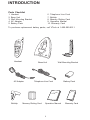
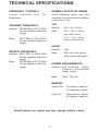
INTRODUCTION
Congratulations! You have purchased
one of the most sophisticated cordless
telephones on the market. The VT
1421 has been designed to offer a new
standard in cordless telephone
technology
The VT 1421 uses special memory
which is not susceptible to power
failures. This provides permanent
storage of all memory dial numbers,
Caller ID information, and security
codes.
Unlike most other cordless phones, the
VT 1421 digitizes your voice using
advanced ADPCM digital voice
encoding to provide noise and
distortion-free performance. In most
conditions, you will not be able to tell
you are using a cordless phone. Gone
are the annoyances of static,
interference and having to listen to
other conversations on your cordless
telephone.
When an optional battery pack is
installed in the base unit, the VT 1421
uses this battery to provided operational
backup in case of power failure. In this
way you have access to handset
functions during total power outage.
Calls can still be placed and received
on the handset without interruption. Up
to 5 hours of backup will be possible
with a fully charged battery pack in the
base unit.
The VT 1421 scrambles your voice
before it transmits. This allows you the
security of knowing that no one can
eavesdrop on your conversations.
The VT 1421 informs you when another
extension is currently in use on the
same phone line. The phone will also
alert you when you are Out of Range,
even when you’re not on the phone!
The VT 1421 decodes and displays
name and/or number Caller ID
information where available and when
the service is subscribed to. The
alphanumeric display can show both
the name and number of the calling
party. Up to 15 name characters or
12 phone number digits (including
spaces) can be displayed.
The VT 1421 has a very unique and
compact design. Using the provided
beltclip, you can easily carry the
handset clipped to your belt or even in
a shirt pocket. Also, if you connect an
optional headset to the 2.5mm headset
jack on the VT 1421, you can have
completely hands-free conversations.
With the VT 1421, the user can easily
answer a call simply by pressing any
key other than the OFF key. In
addition, the handset keypad and
display illuminate while the handset
rings to signal an incoming call. This
is very useful in a dark environment.
1
INTRODUCTION
•
Special Features:
•
•
•
•
•
•
•
•
•
•
•
•
•
•
•
900 MHz Operation.
Fully digital link between handset
and base.
Digitally scrambled voice
communication.
Alphanumeric Call Waiting Caller
ID.
50 Caller ID memory locations.
2 row by 12 character 5x7 dot
matrix alphanumeric display.
Backlit keypad and display on
handset.
21 number / location programmable
memory for up to 20 digit phone
numbers.
10-channel operation with auto
channel selection.
Out-of-Range indication while the
handset is in use or in standby
mode.
Removable handset battery pack.
Spare battery charger in base unit.
Battery backup in case of power
failure (with optional spare battery
pack installed in base).
Face up handset charging.
Easy answer - When the phone
rings, simply press any key other
than OFF to answer.
•
•
•
•
•
•
•
•
•
•
•
•
•
•
Auto hang up when returning the
handset to the base cradle.
Extension in use indicator.
Message waiting indicator for use
with voicemail service.
Multi-level REDIAL; stores last 5
numbers dialed.
24-bit digital security code.
Tone and Pulse dialing.
Low battery detect and warning
indicator.
Up to 7 hours continuous talk time,
or 7 days standby time.
Volume adjustment on Handset.
FLASH and MUTE functions.
Hearing-aid compatible receiver.
Detachable power supply.
Non-volatile storage of security
code, Caller ID and memory dial
records.
Wall mountable base unit.
2.5mm Headset Jack for handsfree operation.
This manual is designed to make you
familiar with the VT 1421. We strongly
recommend you read the entire manual
before using your phone.
2
INTRODUCTION
Parts Checklist
1.
2.
3.
4.
5.
Handset
Base Unit
Wall Mounting Bracket
AC Adapter
Battery Pack
6. Telephone Line Cord
7. Beltclip
8. Memory Dialing Card
9. Operation Manual
10. Warranty Card
To purchase replacement battery packs, call VTech at 1-800-595-9511.
Handset
Base Unit
AC Adaptor
Wall MountIng Bracket
Telephone Line Cord
MEMORY DIALING
•
•
•
•
•
•
•
•
•
•
•
Beltclip
VTech
•
•
•
•
•
•
•
•
•
•
•
Memory Dialing Card
Operation Manual
3
Battery Pack
VTech
Warranty Card
FCC REGULATIONS
This equipment complies with Parts 15
and 68 of the Federal Communications
Commission (FCC) rules for the United
States. Operation is subject to the
following two conditions:
FCC Part 15
Warning: Changes or modifications to
this unit not expressly approved by the
party responsible for compliance could
void the user’s authority to operate the
equipment.
1. This device may not cause
interference, and
The equipment has been tested and
found to comply with part 15 of the FCC
rules. These limits are designed to
provide reasonable protection against
harmful interference in a residential
installation. This equipment generates,
uses and can radiate radio frequency
energy. And, if not installed and used
in accordance with the instruction, may
cause harmful interference to radio or
television reception, which can be
determined by turning the equipment
off and on, the user is encouraged to
try and correct the interference by one
or more of the following measures:
2. This device must accept any
interference, including interference
that may cause undesired
operation of the device.
A label is located on the underside of
the base unit containing the FCC
registration number and Ringer
Equivalence Number (REN) . You
must, upon request, provide this
information to your local telephone
company.
Hearing Aid Compatibility
This equipment is compatible with
inductively coupled hearing aids.
•
•
Should you experience trouble with
this telephone equipment, please
contact VTech at 1-800-595-9511 for
warranty and/or repair information.
The Telephone Company may ask you
to disconnect this equipment from the
line network until the problem has been
corrected.
•
•
4
Re-orient or relocate the base unit.
Increase the separation between
the equipment and receiver.
Connect the equipment into an
outlet or on a circuit different from
that to which the receiver is
connected.
Consult the dealer or a qualified
technician for help.
FCC REGULATIONS
FCC Part 68
manufacturer’s Limited Warranty.
The FCC requires that you connect
your cordless telephone to nationwide
telephone network through a modular
telephone jack (USOC RJ11C, RJ11W
or RJ14).
This equipment may not be used on
coin service provided by the Phone
Company or Party Lines.
The REN is useful in determining the
number of devices you may connect
to your telephone line and still enable
the devices to ring when you receive
a call. The general rule is that the REN
value should not exceed 5.0A total;
however, contact your local telephone
company for the specific number in
your area.
Your local telephone company may
discontinue your service if your
equipment causes harm to the
telephone network. They will notify you
in advance of disconnection, if possible.
During notification, you will be informed
of your right to file a complaint with the
FCC.
Your VT 1421 is designed to operate
at the maximum power allowed by the
FCC. This means your handset can
communicate with the base unit only
over a certain distance - which will
depend on the location of the base unit
and handset, weather, and the
construction and layout of your home
or office.
Occasionally, your local telephone
company may make changes in its
facilities, equipment, operation, or
procedures that could affect the
operation of your equipment. If so, you
will be given advance notice of the
change to give you an opportunity to
maintain uninterrupted service.
The base unit contains no user
serviceable parts.
The handset
contains a user replaceable battery
pack.
If it is determined that your telephone
equipment is malfunctioning, the FCC
requires that it not be used and that
it be unplugged from the modular jack
until the problem has been corrected.
Repairs to this telephone equipment
can only be made by the manufacturer
or its authorized agents or by others
who may be authorized by the FCC.
For repair procedures, follow the
instructions outlined under the
5
IMPORTANT SAFETY INSTRUCTIONS
When using your telephone equipment,
basic safety precautions should always
be followed to reduce the risk of fire,
electric shock and injury to persons,
including the following:
1.
Read and understand all instructions.
2.
Follow all warnings and instructions
marked on the product.
3.
Unplug this product from the wall
outlet before cleaning. Do not use
liquid cleaners or aerosol cleaners.
Use a damp cloth for cleaning.
4.
Do not use this product near water
(for example, near a bathtub,
kitchen sink, or swimming pool).
5.
Do not place this product on an
unstable cart, stand, or table. The
product may fall, causing serious
damage to the product.
6.
7.
This product should be operated
only from the type of power source
indicated on the marking label. If
you are not sure of the type of
power supply to your home, consult
your dealer or local Power
Company.
8.
Do not allow anything to rest on
the power cord. Do not locate this
product where persons walking on
it will abuse the cord.
9.
Never push objects of any kind into
this product through cabinet slots
as they may touch dangerous
voltage points or short out parts
that could result in a risk of fire or
electric shock. Never spill liquid
of any kind on the product.
10. To reduce the risk of electric
shock, do not disassemble this
product, but call VTech
Communications at 1-800-5959511. Opening or removing cabinet
parts other than specified access
doors may expose you to
dangerous voltages or other risks.
Incorrect reassembling can cause
electric shock when the appliance
is subsequently used.
Slots and openings in the cabinet
and the back or bottom are provided
for ventilation. To protect it from
overheating, these openings must
not be blocked by placing the
product on a bed, sofa, rug, or
similar surface.
This product
should never be placed near or
over a radiator or heat register.
This product should not be placed
in a built-in installation where
proper ventilation is not provided.
11. Do not overload wall outlets and
extension cords as this can result
in the risk of fire or electric shock.
6
IMPORTANT SAFETY INSTRUCTIONS
12. Unplug this product from the wall
outlet and refer servicing to VTech
Communications at 1-800-5959511, under the following
conditions:
13. Avoid using a telephone (other
than a cordless type) during an
electrical storm. There may be a
remote risk of electric shock from
lightning.
•
14. Do not use the telephone to report
a gas leak in the vicinity of the leak.
•
•
•
•
•
When the power supply cord or
plug is damaged or frayed.
If liquid has been spilled into the
product.
If the product has been exposed to
rain or water.
If the product does not operate
normally by following the operating
instructions. Adjust only those
controls that are covered by the
operating instructions, because
improper adjustments of other
controls may result in damage and
will often require extensive work by
an authorized technician to restore
the product to normal operation.
If the product has been dropped
and the cabinet has been damaged.
If the product exhibits a distinct
change in performance.
SAVE THESE INSTRUCTIONS
7
THE BATTERY PACK
Alternatively, if you have purchased a
spare battery pack and it has been
charging in the base unit, simply
exchange the drained handset battery
pack with the fully charged battery pack
from the base charger. Place the
drained handset battery pack in the
base charger.
Charging the Handset Battery
Pack
The handset of your VT 1421 cordless
telephone is powered by a rechargeable
battery pack. It charges automatically
whenever the handset is in the base.
You should charge the battery pack for
16 hours when you first receive your
phone. You’ll know the battery pack
needs recharging when:
•
•
•
The base spare battery charger does
not charge a battery pack as quickly
as the handset battery charger. A full
charge requires 24 hours when using
the base unit spare battery charger.
The phone emits a warning tone
when you press the PHONE key.
The low battery message is
displayed on the handset:
It is impossible to overcharge the
battery. The battery pack can be
recharged many times, but if you get
a low battery message even after 16
hours of charging in the base cradle
(or 24 hours in the base spare battery
charger), the battery pack(s) should be
replaced.
The handset seems completely
dead; the display is clear and the
handset does not beep or light
when you press the keys.
To purchase replacement battery
packs, call VTech Communications
at 1-800-595-9511.
To Charge the Battery Pack
To charge the battery pack, place
the handset in the base unit. The
CHARGING indicator will light to show
the handset is seated properly and
the battery pack is charging. It is
recommended that the battery pack be
for at least 16 hours initially, and 8
hours for maintenance charging. You
can use your telephone before that with
diminished capacity, but it is best to
charge the battery pack fully. It will take
several recharge cycles to maximize
the charge capacity of your battery
pack. The maximum battery life
between charges is 7 hours of
continuous talk time or 7 days if
standby time.
A Word about Rechargeable
Batteries
Your battery pack recharges whenever
the handset is returned to the base unit
cradle. You may return the handset
to the cradle whenever it is not in use.
8
THE BATTERY PACK
To Replace the Handset Battery
Pack
5.
Replace the battery case cover
and beltclip.
1.
Remove beltclip (if in use).
6.
2.
Remove the battery case cover.
If the new battery pack is not
already charged, place the handset
in the cradle of the base unit to
allow it to charge for 16 hours.
CAUTION:
To reduce the risk of fire or injury to
persons, read and follow the
instructions below.
3.
4.
1.
Use only VTech rechargeable
battery pack.
2.
Do not dispose of the battery in a
fire. The cell may explode.
IMPORTANT:
Remove the old battery pack.
Save it for recharging in the base
unit spare battery charger. Do not
dispose of this battery in household
garbage.
Do not dispose of this battery in
household garbage. For information
on recycling and proper disposal,
contact your local solid waste collection
or disposal organization.
Place the new battery pack in the
handset. Make sure the metal
contacts on the battery are aligned
with the contacts in the handset
battery compartment.
9
3.
Do not open or mutilate the
battery. Released electrolyte is
corrosive and may cause damage
to the eyes or skin. It may be toxic
if swallowed.
4.
Exercise care in handling batteries
in order not to short the batteries
with conducting materials such as
rings, bracelets, and keys. The
battery or conductor may overheat
and cause burns.
THE BATTERY PACK
temporarily unplug the AC adaptor
from the wall outlet and then plug it in
again. This will reset the battery
charger to ensure a frll battery charging
cycle is started again.
To purchase replacement battery
packs, call VTech Communications
at 1-800-595-9511.
Spare Battery Charger
The VT 1421 has a built-in spare
battery charger, which is located in the
cradle of the base unit.
Power Backup Function
When a spare battery pack is installed
in the base unit, the VT 1421 uses this
battery pack to provide operational
backup in case of a power failure. If
you have a fully charged battery pack
in the spare battery charger and there
is a power outage, you will still be able
to place and receive calls on the
handset for up to 5 hours. When power
backup mode is active the following
message will be displayed:
Note:
In order to benefit from this feature,
you must obtain an optional spare
battery from an authorized dealer, or
by contacting VTech Communications
at 1-800-595-9511.
Installation
1.
Remove the spare battery charger
cover.
2.
Place a battery pack in the spare
battery charger. Make sure the
metal contacts on the battery are
aligned with the contacts in the
spare battery charger.
Replacing a Drained Handset
Battery
The spare battery pack can also be
used to replace a drained handset
battery pack to ensure uninterrupted
use. Be sure to put the drained battery
pack in the spare battery charger for
recharging.
Please note that the spare battery
compartment charges at a slower rate
than a battery pack charging in the
handset. It takes 48 hours to fully
charge a battery pack in the spare
battery charger.
If at any time you find that the battery
does not provide adequate talk time
after a 16 hours of charging, you should
either temporarily remove and replace
the battery in the handset, or,
10
GETTING STARTED
Setting up Your VT 1421
CAUTION
Use only CLASS 2 9V DC POWER
SUPPLY included with your phone.
Choose an area near an electrical
outlet and a telephone wall jack.
AC Power Adapter
Handset Ringer
Plug the AC power adapter into an
electrical outlet and the DC connector
to the back of the base unit.
The handset ringer is programmed ON
as the factory default. Refer to
PROGRAMMING THE RINGER for
more information.
Tone / Pulse Selection
To telephone
jack
To select the desired dialing mode,
follow these steps:
1.
Press the OK key to activate the
menu. The following will be
displayed :
Charge the Battery
2.
Use the
Charge the handset battery pack
before use. The battery pack recharges
automatically whenever the handset is
in the base unit. The batteries must
be charged for 16 hours before using
your phone for the first time.
3.
Press the OK key until you see:
4.
Use the
/
keys to select the
SET DIAL TYPE menu item:
To electrical
outlet
11
/
keys until you see:
GETTING STARTED
5.
Press the OK key to display the
current DIAL TYPE setting and
allow editing of the DIAL TYPE
parameter:
Check for a dial tone. After the battery
pack is charged, pick up the handset
and press PHONE, you should see the
following display:
6.
Use the
/
keys to toggle
between Tone and Pulse.
If not, see IN CASE OF DIFFICULTY.
Fill in the telephone number card on
the base unit.
7.
Press the OK key to confirm your
selection. A confirmation tone will
be generated, and the screen will
display:
MEMORY
•
•
•
•
•
•
•
•
•
•
•
DIALING
•
•
•
•
•
•
•
•
•
•
•
8. Press OFF twice to exit SETUP
MODE.
CAUTION:
1. Never install telephone wiring
during a lightning storm.
Connect Telephone Line Cord
Plug one end of the telephone cord into
a wall jack and the other end into the
back of the base unit.
If the VT 1421 does not detect that an
active telephone line cord is connected,
the following message will be displayed:
12
2.
Never install telephone jacks in
wet locations unless the jack is
specifically designed for wet
locations.
3.
Never
touch
uninsulated
telephone
wires or terminals
unless the telephone lane has
been disconnected at the network
interface.
4.
Use caution when installing or
modifying telephone lines.
WALL MOUNTING
The Wall Mounting bracket is
designed to fit on standard Wall
Mounting plates.
1.
2.
Choose a spot near an electrical
outlet and a telephone jack.
Your phone requires a modular
telephone jack (120v AC). The
power cord is six feet long; make
sure there is an electrical outlet
within reach of the base. A wall
switch should not control the
outlet. If the switch is ever turned
off, your phone may not function
(unless you have a fully charged
battery in the spare battery
charger).
Position the wall-mounting
bracket on the base. Line up the
tabs on the wall-mounting bracket
with the holes on the bottom of the
base. Snap the wall-mounting
bracket firmly in place.
13
3.
Mount the base on the wall.
Position the base so the mounting
studs will fit into the holes on the
wall-mounting bracket. Slide the
base down on the mounting studs
until it locks into place
4.
Connect the telephone line cord.
The telephone line cord has a
snap-in plug at each end. Insert
one end into the jack on the back
of the base, and insert the other
end of the plug into the wall jack.
5.
Plug the AC adapter into an
electrical outlet and the DC
connector into the power jack
located on the back of the base
unit.
THE HANDSET LAYOUT
RETRACTABLE ANTENNA
2.5MM HEADSET JACK
DISPLAY
OK key
OFF key
PHONE / FLASH key
VOLUME / MENU
UP key
VOLUME / MENU
DOWN key
DIALING keys (0-9)
TONE (Temporary Tone)
PAUSE kkey
DELETE key
MICROPHONE
CHARGING
CONTACTS
14
THE BASE UNIT LAYOUT
SPARE BATTERY CHARGE
COMPARTMENT
MEMORY DIALING
•
•
•
•
•
•
•
•
•
•
•
•
•
•
•
•
•
•
•
•
•
•
MEMORY
DIALING CARD
POWER indicator
PAGE key
SPARE BATTERY
indicator
IN-USE/CHARGING
indicator
MESSAGE WAITING
indicator
15
BASE UNIT FEATURES
Status
POWER
IN USE (off hook)
RINGING
CHARGING
SPARE BATTERY
MESSAGE
POWER BACKUP
Type Description
When the POWER LED is lit solid RED, it indicates that
there is power to the base unit.
When the IN USE/CHARGING LED is lit solid GREEN
it indicates that the phone is currently IN USE.
The IN USE/CHARGING LED flashes GREEN in
cadence with an incoming call.
When the IN USE/CHARGING LED is lit solid RED it
indicates that the handset is charging.
When this LED is lit solid RED it indicates that a spare
battery is installed in the base unit,
When this indicator is flashing RED, it indicates that
messages are waiting in your voicemail (service
provided by some local telephone companies).
When the POWER LED blinks RED, it indicates that the
base is running off of the spare battery and is in POWER
BACKUP mode
To stop the handset from ringing during
a PAGE, press OFF.
PAGE Key / Handset locator
As a convenience feature, the PAGE
key on the base can be used to page
a handset as a means of signaling the
user or to help locate a misplaced
handset.
Pressing the PAGE key when the
telephone is in use causes the handset
to ring once and display the above
message for less than 2 seconds.
Pressing the PAGE key when the
telephone is on hook causes the
handset to ring 5 times and display the
message:
16
QUICK REFERENCE GUIDE
Handset Menu Operation
On Hook Stage
Off Hook Stage
OK key
OK key
REDIAL MEMORY
MUTE MICROPHONE?
• Use Redial (p.20)
• Mute the Microphone on Call (p.18)
SET UP
SPEED DIAL MEMORY
• Set Ring Type (p.27)
• Dial from Memory (p.18)
• Set Ring Volume (p.27)
• Delete Speed Dial Memory (p.19)
• Set Dial Type (p.28)
• Set Keyclick (p.28)
CID MEMORY
• Reveiw Caller ID Record (p.21)
CLEAR MEMORY
• Dailing From Caller ID Memory (p.22)
• Clear VMWI (p.25)
• Delete Caller ID Memory (p.23)
• Clear Speed Dial Memory (p.19)
• Clear CID Memory (p.23)
REDIAL MEMORY
• Use Redial (p.20)
PROGRAM SPEED DIAL
• Story Dial Memory (p.18)
SPEED DIAL MEMORY
• Dial from Memory (p.19)
• Delete Speed Dial Memory (p.19)
CID MEMORY
• Reveiw Caller ID Record (p.21)
• Dailing From Caller ID Memory (p.22)
• Delete Caller ID Memory (p.23)
17
QUICK REFERENCE GUIDE
Setup
•
•
•
•
Plug AC adapter into a standard
electrical outlet and base unit.
Let handset battery pack charge for
16 hours before first use.
Set TONE/PULSE selection from
SETUP menu.
Connect the telephone line cord to
the base unit and telephone jack.
•
Then press OK key again to confirm
the MUTE feature. The screen
displays:
•
To release the MUTE condiction
and return to the call, press either
PHONE or OFF key.
Making Calls
•
Press the PHONE key. When
HANDSET ON is displayed and
you hear dial tone, dial the number.
To Page The Handset
•
OR
•
•
Enter the number to be dialed on
the display (predial) and then press
the PHONE key.
To page from the base, press the
PAGE key on the base.
To cancel the page either press
PAGE again on the base, or press
OFF on the handset.
Storing Memory Dial Numbers
Answering Calls
•
•
•
To answer a call, press any key
other than OFF. The handset will
not auto answer when lifted off the
base cradle.
•
•
Ending A Call
•
The phone should be OFF.
Enter the number you wish to store
on the display (up to a maximum
of 20 digits).
Press OK key to display the menu.
Use the
keys to locate the
following menu item:
Press OFF or place the handset in
the cradle to end a call.
To MUTE A Call
•
During an active call, press the OK
key. You will see the screen
displays:
18
•
Press the OK key to select the
PROGRAM SPEED DIAL menu
item:
•
Enter the 2-digit speed dial memory
location (00..20) you wish to store
the number in. A confirmation tone
will follow.
QUICK REFERENCE GUIDE
the following LCD message:
Dialing From Memory
•
•
•
•
•
•
The phone should be OFF.
Press the OK key to activate the
menu.
Use the
keys to locate the
following menu item:
After the Speed Dial Location is
deleted, the VT 1421 will return to
Speed Dial Memory review mode.
You can also delete the entire contents
of the Speed Dial Memory.
Press the OK again. The handset
will display:
You can directly enter the 2-digit
location number (i.e. 18), or you can
use the
keys to sequentially
scroll through the memory locations.
Once you have selected the
memory location to be dialed, press
the PHONE key to dial the number.
•
•
Press OK to activate the menu.
Use the
keys to locate the
following menu item:
•
Press OK to enter CLEAR
MEMORY mode. Use the
keys
to locate the following menu item:
Press and hold the 0 key to clear
Caller ID memory. After 1 second,
the following message will be
displayed:
•
Deleting Speed Dial Memory
While reviewing any of the Speed Dial
Location, you can delete the current
Speed Dial Location in view. To do this,
press and hold the 0 key until the LCD
displays the following message:
•
To confirm the deletion, press the
0 key again. While the memory is
being cleared, the following
message is displayed:
•
Press OFF to exit.
To exit without deleting the current
Speed Dial Location, press the OFF
key.
To proceed with the deletion, press the
0 key again. For an example, you want
to delete location S01. You will see
19
QUICK REFERENCE GUIDE
Caller ID
Using Redial
•
To view information stored in Caller
ID memory, press the OK key to
activate the menu.
Use the
keys to locate the
following menu item:
•
Press the OK key again to begin
reviewing Caller ID memory.
The display will show the most
recent call received. For example:
•
•
•
•
•
•
•
•
•
•
Use the
keys to scroll through
the Caller ID memory.
To view additional name characters
not shown on the display, press
and hold the 9 key.
To view the time and date of the
call press and hold the 7 key. You
will see a display like:
•
To view information stored in
REDIAL memory, press the OK key
to activate the menu.
Use the
keys to locate the
following menu item:
Press the OK key again to access
REDIAL memory.
Use the
keys to scroll through
REDIAL memory. The VT 1421 will
store the last 5 numbers dialed in
REDIAL memory, for example:
Once you have found the number
you want to dial press the PHONE
key.
FLASH
You can use your VT 1421 with
services such as Call Waiting. Simply
press the PHONE key to FLASH the
line.
To exit press OFF.
20
CALLER ID
Your VT 1421 cordless phone is
capable of displaying the name and/
or phone number of the person calling,
before you answer the phone.
Subscription to Caller ID service through
your local telephone company is
required to utilize this feature.
NOTE:
You must be in an area where Caller
ID service is available and you must
subscribe to it to use this feature.
If you do not subscribe to Caller ID
service, the phone will still operate
normally, except that the Caller ID
information is not received or
displayed.
If you subscribe to alphanumeric (name
and number) Caller ID service, the
calling party’s name and phone number
(when available) will be displayed on
the handset screen while the phone is
ringing.
Receiving And Storing Calls
This unit receives and displays all
Caller ID information: the caller’s
telephone number, the caller’s name
and the exact date and time of the call
(as provided by the local telephone
company).
If you subscribe to numeric (number
only) Caller ID service, the calling
party’s phone number (when available)
will be displayed on the handset screen
while the phone is ringing.
The phone sequentially numbers these
call records and retains them in memory
for later review. The unit can store up
to 50 numbers in memory.
Call Waiting Caller ID (Type II)
Your VT 1421 cordless phone is also
capable of displaying Caller ID
information in connection with a Call
Waiting signal. If you are on a call, and
receive a Call Waiting alert signal, the
handset will display the name and/or
number (when available) of the party
trying to reach you.
As above,
subscription to Call Waiting ID service
through your local phone company is
required in order to utilize this feature.
Once Caller ID memory is full, any new
call forces a deletion of the oldest call
record.
New Call Counter
The VT 1421 keeps track of new Caller
ID records. For example:
A Word About Caller ID
Due to regional incompatibilities, Caller
ID information may not be available for
every call you receive. In addition, the
calling party may intentionally block
their name and phone number from
being sent.
The above display indicates that three
new Caller ID records have been
received since you last reviewed your
Caller ID memory.
21
CALLER ID
Reviewing Caller ID Memory
Dialing From Caller ID Memory
The VT 1421 stores up to 50 Caller ID
records in memory. Using the
keys,
you can sequentially scroll through the
Caller ID records.
•
•
•
•
To view information stored in Caller
ID memory, press the OK key to
activate the menu.
Use the
keys to locate the
following menu item:
•
•
•
•
•
•
•
•
Press the OK key again to begin
reviewing Caller ID memory.
The display will show the most
recent call received. For example:
Press the OK key again to begin
reviewing Caller ID memory.
The display will show the most
recent call received. For example:
•
•
To view information stored in Caller
ID memory, press the OK key to
activate the menu.
Use the
keys to locate the
following menu item:
Use the
keys to scroll through
the Caller ID memory.
To view additional name characters
not shown on the display, press
and hold the 9 key.
To view the time and date of the
call press and hold the 7 key. You
will see a display like:
Use the
keys to scroll through
the Caller ID memory.
To dial the number exactly as it is
displayed in Caller ID memory,
simply press the PHONE key.
Using the display above as an
example, the actual digits dialed
would be: 503-596-1200.
11 Digit Dialing
•
To dial 1 + Area Code + 7 Digit
Phone Number, press the 1 key
when reviewing Caller ID memory.
For example:
•
Then press PHONE to dial.
To exit press OFF.
22
CALLER ID
10 Digit Dialing
•
•
To dial Area Code + 7 Digit Phone
Number, press the 2 key when
reviewing Caller ID memory. For
example:
The occasional appearance of CALL
ID ERROR on your VT 1421 display
does not indicate a problem with your
unit or telephone line. However, if this
appears frequently, you may want to
notify your telephone company.
Then press PHONE to dial.
The name and number field may also
display ‘PRIVATE’ or ‘UNAVAILABLE’
if this information is blocked or is not
provided by your Telephone Company.
Examples of these displays follow:
8 Digit Dialing
•
•
To dial 1 + 7 Digit Phone Number,
press the 3 key when reviewing
Caller ID memory. For example:
Then press PHONE to dial.
7 Digit Dialing
•
•
•
To dial 7 Digit Phone Number only,
press the 4 key when reviewing
Caller ID memory. For example:
Deleting Call ID Memory
While reviewing any of the Caller ID
records, you can delete the current
Caller ID record in view. To do this,
press and hold the 0 key until the LCD
displays the following message:
Then press PHONE to dial.
To exit from Caller memory review
without dialing, press the OFF key
twice.
Special Message Indicators
Occasionally, errors may occur when
Caller ID data is transmitted from your
Telephone Company. If this happens,
the VT 1421 may display the following
message:
To exit without deleting the current
Caller ID record, press the OFF key.
23
CALLER ID
To proceed with the deletion, press the
0 key again. You will see the following
LCD message:
After the Caller ID record is deleted,
the VT 1421 will return to Caller ID
review mode.
•
Press and hold the 0 key to clear
Caller ID memory. After 1 second,
the following message will be
displayed:
•
To confirm the deletion, press the
0 key again. While the memory is
being cleared, the following
message is displayed:
•
Press OFF to exit.
You can also delete the entire contents
of the Caller ID memory.
•
•
•
Press OK to activate the menu.
Use the
keys to locate the
following menu item:
Press OK to enter CLEAR
MEMORY mode. Use the
keys
to locate the following menu item:
24
ADVANCED FUNCTIONS
Call Waiting
•
Use the
keys to locate the
following menu item:
•
Press the OK key again to enter
CLEAR MEMORY mode. Then
use the
keys to scroll to the
following option:
•
Press and hold the 0 key for 1
second. You will see the following
display :
•
To confirm the deletion, press the
0 key again. While the memory is
being cleared, the following
message is displayed :
•
Press OFF to exit.
Call Waiting is a subscription service
available from most local telephone
service providers. Contact your provider
for details.
While you are on a call, you will hear
an alert signal (if you subscribe to this
service), indicating that a second caller
is trying to reach you. You can switch
from the active call to the Call Waiting
call simply by pressing the PHONE key
to FLASH the line. To return to the
original call, press the PHONE key
again.
Message Waiting
Your VT 1421 is capable of detecting
a Visual Message Waiting Indication,
generated by many telephone service
providers. If you subscribe to Voice
mail service from your local Telephone
Company, and Visual Message Waiting
Indication is provided, the VT 1421 will
display the following message to alert
you of new, unplayed Voice mail
messages:
Once you play all of your new Voice
mail messages, the MSG WAITING
indication will be automatically cleared
from the display.
Temporary TONE
If you have PULSE telephone service,
this feature allows you to temporarily
switch to TONE dialing for access to
answering machines, bank by phone,
use of calling cards and other special
services.
You can also clear the MSG WAITING
indication manually by performing the
following steps:
•
Press the OK key to activate the
menu.
25
ADVANCED FUNCTIONS
First, dial the call normally. Then
activate the Temporary Tone feature
by pressing the
(TONE) key. You
can then press the numbers or symbols
you need, and your phone will send the
proper signals.
Headset Jack
The VT 1421 has a standard 2.5mm
headset jack. When a compatible
headset is connected, the earpiece
receiver and handset microphone are
disabled.
*
When you end the call, the phone will
automatically go back to PULSE
service.
Ear Piece Volume Adjustment
The volume level of the incoming
audio can be adjusted by pressing
the
or
keys. This can only be
done while the phone is in use.
The initial press of either the
or
a keys will display the current ear
piece volume setting.
To adjust the volume press the
or
keys to select the desired
level. As you press the keys, the
volume indicator will increase or
decrease accordingly.
Extension In Use Indication
When another telephone on the same
line is currently in use, the VT 1421
displays the following message:
26
SETUP MODE OPTIONS
Set Ring Volume
The VT 1421 has four user configurable
setup options which are accessible
through the menu.
The VT 1421 has two programmable
ringer volume settings, High or Low.
The default ringer volume setting is
High.
Set Ring Type
The VT 1421 has four programmable
ringer tones, and the option to turn OFF
the ringer. The default ringer setting is
ring type 1.
•
•
•
•
•
•
Press OK to activate the menu.
Use the
keys to locate the
following menu item:
•
Press OK to enter SETUP MODE.
Use the
keys to locate the
following menu item:
•
Press the OK key to display the
current volume setting.
For
example:
•
Use the
keys to select the
desired volume setting. As you
scroll through the available settings,
the ringer will activate for 2 seconds.
Press OK to save the new ringer
volume setting. A confirmation
tone will be generated.
Press OFF to exit.
Press OK to activate the menu.
Use the
keys to locate the
following menu item:
Press OK to enter SETUP MODE.
The following will be displayed:
Press the OK key to display the
current type setting. For example:
•
•
•
•
Use the
keys to select the
desired ring type. As you scroll
through the available tones(1-4, or
OFF), each ringer will activate for
2 seconds.
Press OK to save the new ringer
type. A confirmation tone will be
generated.
Press OFF to exit.
•
27
SETUP MODE OPTIONS
Dial Type Selection
Keyclick Selection
The VT 1421 supports either Tone or
Pulse dialing. The default dial type is
Tone.
• Press OK to activate the menu.
• Use the
keys to locate the
following menu item:
The VT 1421 can be set to generate
a brief tone (or Keyclick) every time a
key is pressed. This setting can be set
to be either On or Off. The default
setting is Keyclick On.
•
•
•
•
•
•
•
Press OK to activate the menu.
Use the
keys to locate the
following menu item:
•
Press OK to enter SETUP MODE.
Use the
keys to locate the
following menu item:
•
Press the OK key to display the
current KEYCLICK setting. For
example:
•
Use the
keys to select the
desired keyclick setting.
Press OK to save the new setting.
A confirmation tone will be
generated.
Press OFF to exit.
Press OK to enter SETUP MODE.
Use the
keys to locate the
following menu item:
Press the OK key to display the
current dial type setting.
For
example:
Use the
keys to select either
TONE or PULSE dial type. The
setting will depend on the type of
your local telephone company.
Press OK to save the new setting.
A confirmation tone will be
generated.
Press OFF to exit.
•
•
28
MAINTENANCE
Taking Care or Your Telephone
Cleaning your telephone
Your VT 1421 cordless telephone
contains sophisticated electronic parts,
so it must be treated with care.
Your telephone has a durable plastic
casing that should retain its luster for
many years. Clean it only with a soft
cloth slightly dampened with water or
a mild soap. Do not use excess water
or cleaning solvents of any kind.
Avoid rough treatment
Place the headset down gently. Save
the original packing material to protect
your telephone if you ever need to ship
it.
Remember that electrical appliances
can cause serious injury if used
when you are wet or standing in
water. If your base unit should fall
into water, DO NOT RETRIEVE IT
UNTIL YOU UNPLUG THE POWER
CORD AND TELEPHONE CORDS
FROM THE WALL. Then pull the
unit out by the unplugged cords.
Avoid water
Your telephone can be damaged if it
gets wet. Do not use the headset
outdoors in the rain, or handle it with
wet hands. Do not install your base
unit near a sink, bathtub or shower.
Electrical storms
Electrical storms can sometimes cause
power surges harmful to electronic
equipment.
For your own safety, use caution when
using electric appliances during storms.
29
WARRANTY
WHAT DOES OUR WARRANTY COVER?
• Any defect in material or workmanship.
FOR HOW LONG AFTER THE ORIGINAL PURCHASE?
• To the original purchaser only – ONE YEAR.
WHAT WILL VTECH DO?
• At our option, repair or replace your unit.
HOW DO I SEND MY UNIT, IN OR OUT OF WARRANTY?
• Call VTech Communications customer service for Return Authorization at :
1-800-595-9511
• Properly pack your unit. Include any cables & accessories, which were originally
provided with the product. We recommend using the original carton and packing
materials.
• Include in the package a copy of the sales receipt or other evidence of date
of original purchase (if the unit was purchased within the last twelve months).
• Print your name and address, along with a description of the defect, and include
this in the package.
• Include payment for any service or repair not covered by warranty, as
determined by VTech Communications.
• Ship the unit via UPS Insured, or equivalent to:
VTECH COMMUNICATIONS
11035 SW 11th STREET
BDLG. B, SUITE 270
BEAVERTON, OREGON 97005
VTech Communications assumes no responsibility for units sent without prior
Return Authorization
WHAT DOES OUR WARRANTY NOT COVER?
• Batteries
• Damage from misuse, neglect, or acts of nature (lightning, floods, power surges,
etc.)
• Products which may have been modified or incorporated into other products
• Products purchase and/or operated outside the USA,its territories, or Canada.
• Products serviced by the owner or a service facility not expressly authorized
by VTech Communications
• Products purchased more than 12 months from current date
• Units purchased in “AS IS” condition or units purchased as “Distressed
Merchandise”.
HOW DOES STATE LAW RELATE TO THIS WARRANTY?
• This warranty gives you specific rights. You may also have other rights that
vary from state to state.
IF YOU PURCHASED YOUR TELEPHONE IN CANADA
Please call 1-604-273-5131
30
TECHNICAL SPECIFICATIONS
FREQUENCY CONTROLL
Crystal Controlled
Synthesizer
Dual
NOMINAL EFFECTIVE RANGE
PLL
Actual operating range may vary
according to environmental conditions
at the tine of use.
TRANSMIT FREQUENCY
SIZE
Handset : 925.05 MHz to 927.75 MHz
(all ten channels within this
range)
Handset :
150 x 60 x 35mm
Base :
166 x 122 x 116mm
(with wall mount)
Base :
157 x 113 x 116mm
(without wall mount)
902.3 MHz to 905.0 MHz
(all ten channels within this
range)
WEIGHT
RECEIVE FREQUENCY
Handset : 902.3 MHz to 905.0 MHz
(all ten channels within this
range)
Base :
925.05 MHz to 927.75 MHz
(all ten channels within this
range)
Handset :
145g
Base :
320g (with wall mount)
290g (without wall mount)
POWER REQUIREMENTS
Handset : Self-contained nickelcadmium rechargeable
battery supply.
Base :
9VDC, 300 mA
MEMORY
Speed Dial : 20 memory locations
20 digits per location
Caller ID :
Alphanumeric display
50 memory locations
Specifications are typical and may change without notice.
31
TABLE OF CONTENTS
Page
INTRODUCTION ............................................................................................................... 1
Special Features .............................................................................................................. 2
Parts Check List ............................................................................................................... 3
FCC REGULATIONS ........................................................................................................ 4
IMPORTANT SAFETY INSTRUCTIONS ........................................................................ 6
THE BATTERY PACK ...................................................................................................... 8
GETTING STARTED ......................................................................................................... 11
WALL MOUNTING .......................................................................................................... 13
THE HANDSET LAYOUT .................................................................................................. 14
THE BASE UNIT LAYOUT ................................................................................................ 15
BASE UNIT FEATURES .................................................................................................. 16
QUICK REFERENCE GUIDE ........................................................................................... 17
Handset Menu Operation ................................................................................................ 17
Setup ................................................................................................................................ 18
Making Calls ...................................................................................................................... 18
Answering Calls ................................................................................................................ 18
Ending a Call ................................................................................................................... 18
To Mute a Call ................................................................................................................... 18
To Page The Handset ..................................................................................................... 18
Storing Memory Dial Numbers ...................................................................................... 18
Dialing From Memory ........................................................................................................ 19
Deleting Speed Dial Memory ............................................................................................ 19
Caller ID ........................................................................................................................... 20
Using Redial ..................................................................................................................... 20
Flash ................................................................................................................................ 20
CALLER ID ...................................................................................................................... 21
Call Waiting Caller ID (TypeII) ............................................................................................ 21
A Word About Caller ID ....................................................................................................... 21
Receiving And Storing Calls .............................................................................................. 21
New Call Counter ............................................................................................................. 21
Reviewing Caller ID Memory ............................................................................................. 22
Dialing From Caller ID Memory ........................................................................................ 22
Special Message Indicators .............................................................................................. 23
Deleting Caller ID Memory ............................................................................................ 23
ADVANCED FUNCTIONS ................................................................................................. 25
Call Waiting ....................................................................................................................... 25
Message Waiting ............................................................................................................... 25
Temporary TONE ............................................................................................................... 25
Ear Piece Volume Adjustment ............................................................................................ 26
Extension In Use Indication ............................................................................................ 26
Headset Jack .................................................................................................................. 26
Set Ring Type ..................................................................................................................... 27
Set Ring Volume ............................................................................................................... 27
Dial Type Selection ........................................................................................................... 28
Keyclick Selection .............................................................................................................. 28
MAINTENANCE ................................................................................................................ 29
WARRANTY ...................................................................................................................... 30
TECHNICAL SPECIFICATIONS ....................................................................................... 31
32
VTECH COMMUNICATIONS LTD.
Is a trademark of VTECH COMMUNICATIONS LTD.., a member
of THE VTECH GROUP OF COMPANIES.
Distributed in the U.S.A. by VTECH Communications, Beaverton, Oregon.
Distributed in Canada by VTECH Electronics Canada Ltd., Suite 200 - 7671 Alderbridge
Way Richmond, B.C. V6X 1Z9.
Copyright 1996 for VTECH COMMUNICATIONS LTD..
91-4064-10-00
ISSUE 0