1
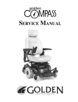
Compass
™
Owner’s Manual
Compass ™
Center-Wheel Drive Power Chair
GP600 SS/GP601 SS
GP600 CC/GP601 CC
401 Bridge Street, Old Forge PA 18518
Tel: (800) 624-6374 Fax: (800) 628-5165
www.goldentech.com
Y O U R
L I F E
I N
M O T I O N
Compass Owner’s Manual – Models # : GP600 SS, GP600 CC, GP601 SS, GP601 CC
Revised 02/20/08
FOR YOUR RECORDS
Please fill in your Compass™ information below. This information
will be useful in the event that you ever need to contact Golden
Technologies, Inc. concerning your power chair.
Your Compass ™
Model __________________
Serial Number _______________
Date of Purchase _______
Body Color __________________
Options ________________
Your Golden Technologies, Inc. representative or dealer
Name ____________________________________
Company ________________________________
Address _________________________________
Please remember to fill in and return your warranty registration
card.
2
Compass Owner’s Manual – Models # : GP600 SS, GP600 CC, GP601 SS, GP601 CC
Revised 02/20/08
CONTENTS
INTRODUCTION ……………………………………………………
4
SAFETY..............................................................……….. 5-8
EMI/RFI ........................................................…….…….. 9
SPECIFICATIONS…………………………………………………… 10
ASSEMBLY……………………………………………………………
11-15
COMFORT SETTINGS…………………………………………….. 16-21
OPERATION/DIAGNOSTICS ……………………………………. 22-28
BATTERY CHARGING ……………………………………………. 29
CARE AND MAINTENANCE ……………………………………..
30
DISASSEMBLY ……………………………………………………… 31
WARRANTY ………………………………………………………….
32
REGISTRATION CARD …………………………………………… 33
3
Compass Owner’s Manual – Models # : GP600 SS, GP600 CC, GP601 SS, GP601 CC
Revised 02/20/08
INTRODUCTION
Congratulations on the purchase of your new Compass™ power chair. The Center-wheel
drive Compass™ combines cutting-edge technology with an attractive design that is also
highly functional in today’s world. We at Golden Technologies, Inc. know that you have
chosen a power chair that will give you years of dependable operation and also will
enhance the quality of your life by providing you with the mobility to experience an active
daily lifestyle.
Even though your new Compass™ is both user-friendly and designed for maximum
maneuverability in even the tightest spaces, we ask that you please read, understand
and follow all of the instructions and suggestions in this manual before you operate your
Compass™ for the first time. The safe use of your new power chair is very important to
us.
If you feel that you do not understand the instructions and suggestions presented in this
owner’s manual, or if, for any reason, you do not feel capable of performing the activities
necessary to assemble, disassemble, operate, or maintain your Compass™ please contact
your local Golden Technologies, Inc. representative or call Golden Technologies, Inc.
Technical Support Services at (800) 624-6374.
Golden Technologies, Inc. cannot be held responsible for personal injury or property
damage resulting from the unsafe or the improper use of any of our broad range of
health and personal mobility products. Our Research and Development Department, our
Quality Control Department, and our Engineering Department have used the latest
product specifications and the latest product design information to produce this owner’s
manual. Golden Technologies, Inc. reserves the right to implement changes into our
product lines when those changes become desirable or necessary. If changes are
implemented into our product line, there may be minor differences between the product
you purchased and the illustrations and instructions in this owner’s manual.
Please fill out and mail the enclosed warranty registration card on page 32. We at
Golden Technologies, Inc. would appreciate hearing about the dependability of your
Compass™ and about the convenience of mobility it has provided for you. We would also
appreciate hearing about the service you received from your local Golden Technologies,
Inc. representative.
Golden Technologies, Inc.
401 Bridge Street
Old Forge, PA 18518
Phone:
(570) 451-7477
Fax:
(570) 451-7494
Toll free: (800) 624-6374
Web Site: www.goldentech.com
4
Compass Owner’s Manual – Models # : GP600 SS, GP600 CC, GP601 SS, GP601 CC
Revised 02/20/08
SAFETY
Your Compass™ is a battery-operated personal mobility vehicle. Please exercise caution
and consideration when you are operating it. Driving your Compass™ carefully and
thoughtfully will help ensure your personal safety and the safety of other people.
NOTE: Before learning to operate your Compass™, have your Golden Technologies,
Inc. representative determine if it is advisable for you to practice getting on
and off your Compass™ and operating it in the presence of an attendant.
BEFORE GETTING ON YOUR Compass™
♦
♦
♦
♦
♦
Check to be certain that the power is turned off. See “Operation” on pages 22-27.
This will eliminate the possibility of accidentally activating the joystick and causing
injury to yourself or to others.
Check to be certain that your Compass™ is not in freewheel mode. See the
“Operation” section on pages 22-27.
Flip up the armrests.
If your chair is equipped with leg rests, move them to the sides.
If your chair is equipped with a footrest, flip it to the “up” position.
GETTING ON YOUR Compass™
♦ While being careful not to entangle yourself in the leg rests or the footrest, seat
yourself comfortably and securely on the seat.
♦ Adjust the leg rests or flip down the footrest.
♦ Flip down or replace the armrests.
♦ Fasten the lap belt, if your chair is so equipped.
GETTING OFF YOUR Compass™
♦ Make certain that the power is turned off.
♦ Unfasten the lap belt, if your chair is so equipped.
♦ Flip up the armrests.
♦ Flip up the footrest, or move the leg rests to the sides.
♦ While being careful not to entangle yourself in the leg rests or the footrest,
carefully stand and step away from the chair.
MAXIMUM WEIGHT
Your Compass™ has been rated to a maximum payload (passenger and anything else
being carried on the Compass™) of 300 pounds. Exceeding the maximum weight rating
will void the warranty.
Exceeding the maximum weight rating may result in injury to yourself and to others.
This will also void your warranty.
5
Compass Owner’s Manual – Models # : GP600 SS, GP600 CC, GP601 SS, GP601 CC
Revised 02/20/08
SAFETY
DRIVING ON AN INCLINE
♦
♦
♦
♦
♦
♦
♦
Drive with caution when attempting to negotiate any incline, even handicap access
ramps.
Always climb or descend a gradient by driving straight up or straight down the face of
the slope.
Do not traverse or drive across the face of a gradient.
Do not attempt to negotiate an incline that is covered with snow, ice, cut or wet grass,
leaves, or any other potentially hazardous material.
Do not back down an incline.
Try to keep your Compass™ moving when climbing an incline. If you do come to a
stop, restart and accelerate slowly and carefully.
Do not try to descend or climb an incline that is greater than the maximum incline
stated in the specifications section of this manual.
If, while you are driving down a slope, your chair starts to move faster
than you feel is safe, gently release the joystick and allow your
Compass™ to come to a stop. When you feel that you again have
control of your power chair, adjust the speed control to a lower setting
then push the joystick forward and continue safely down the remainder
of the slope.
MEDICATION
Always check with your physician to determine if any of the medications you are taking
may affect your judgment and/or your ability to operate your Compass™.
Do not connect or allow anyone except an authorized Golden
Technologies, Inc. representative to connect any electrical or
mechanical device to your Compass™. Unauthorized accessories will
void the warranty and may cause injury.
6
Compass Owner’s Manual – Models # : GP600 SS, GP600 CC, GP601 SS, GP601 CC
Revised 02/20/08
SAFETY
♦
Do not attempt to use your Compass™ on an escalator. Always use an elevator.
♦
Do not carry passengers on your power chair.
♦
Do not operate your Compass™ if it is not functioning properly.
♦
Use caution when driving on soft or uneven surfaces such as grass, gravel, and on
decks where there is no railing.
♦
Never drive on the roadway, except when you must cross the street.
♦
Always cross streets at intersections and use the most direct route, making sure
that your path is clear and that you are visible to motor traffic.
♦
Never drive your Compass™ up or down a step or curb that is higher than 1 1/2
inches.
♦
Never back up or down a step or curb.
♦
Never operate your Compass™ while you are under the influence of alcohol.
♦ Do not operate or store your power chair where it will be exposed to rain, snow, mist,
and below freezing temperatures.
♦ Do not operate your power chair on slippery, icy or salted surfaces.
♦ Never sit on your power chair when it is in freewheel mode and on an incline or
decline.
♦ Never place your power chair into freewheel mode without a trained assistant
present.
♦ Do not sit on your power chair when it is freewheel mode without the presence of a
trained assistant.
♦ Do not modify your power chair in any way that is not authorized by Golden
Technologies.
♦ Do not disassemble the tire. If disassembly is required, have your authorized Golden
Compass dealer perform any necessary maintenance or repair.
♦
Do not attempt to inflate the tires of your Golden Compass™. Your Golden
Compass™ is equipped with foam-filled flat free tires that do not require inflation.
7
Compass Owner’s Manual – Models # : GP600 SS, GP600 CC, GP601 SS, GP601 CC
Revised 02/20/08
SAFETY
Please be sure to follow this important warning when transferring onto or off of the
Golden Compass power wheelchair:
NEVER TRANSFER ONTO OR OFF OF THIS POWER WHEELCHAIR USING THE SEAT
BACKREST FOR SUPPORT DURING TRANSFER. THE SEAT BACK MAY FOLD DOWN
AND MAY CAUSE YOU TO LOSE YOUR BALANCE AND COULD RESULT IN
PERSONAL INJURY.
8
Compass Owner’s Manual – Models # : GP600 SS, GP600 CC, GP601 SS, GP601 CC
Revised 02/20/08
EMI/RFI
The rapid development of electronics, especially in the area of communications, has
saturated our environment with electromagnetic (radio) waves that are emitted by
television transmitters, cellular phones, citizen’s band radios (CBs), amateur radios (ham
radios), wireless computer links, microwave transmitters, paging transmitters, etc.
These electromagnetic (EM) waves are invisible and increase in strength the closer one
gets to the source of transmission. When these energy waves act upon electrical devices
and cause them to malfunction or to function in an erratic or uncontrolled manner, they
are referred to as Electromagnetic Interference (EMI) or Radio Frequency Interference (RFI).
EMI/RFI AND YOUR Compass™
All electrically powered vehicles, including power chairs are susceptible to EMI/RFI. This
interference could result in abnormal, unintended movement of a power wheelchair.
The FDA has determined that each make and model of power chair can resist EMI/RFI to
a certain level. The higher the level of immunity, the greater the degree of protection
from EMI/RFI measured in volts per meter (V/m). The FDA has also determined that
current technology is capable of providing 20 V/m of immunity to EMI/RFI, which would
provide useful protection against common sources of interference.
Based on that determination, the FDA has written to the manufacturers of power wheelchairs and asked them to test their new products to be certain that they provide a reasonable degree of immunity to EMI/RFI. The FDA suggests that power chairs should
have an immunity level of 20 V/m.
The immunity level of the Compass™ is unknown.
EMI/RFI RECOMMENDATIONS
♦ Do not turn on or use hand-held personal electronic communication devices such as
cellular phones, walkie-talkies, and CB radios while your power chair is turned on.
♦ Be aware of any nearby transmitters (radio, television, microwave, etc.) on your intended route and avoid operating your chair close to any of those transmitters.
♦
Turn off the power if your Compass™ is going to be in a stationary position for any
length of time.
♦
Be aware that adding accessories or components or modifying your power chair may
make it more susceptible to EMI/RFI.
♦
If unintended movement or brake release occurs, turn your power chair off as soon
as it is safe to do so.
♦ Report all incidents of unintended movement or brake failure to your Golden representative or to Golden Technologies, Inc. at (800) 624-6374.
Turn off your power chair as soon as it is safely possible if
unintended or uncontrollable motion occurs or if unintended brake
release occurs.
9
Compass Owner’s Manual – Models # : GP600 SS, GP600 CC, GP601 SS, GP601 CC
Revised 02/20/08
SPECIFICATIONS
Weight
Base
Seat Arms
Seat (18 X 18 Solid Pan Seat)
Seat (18 X 18 Captain's Chair Seat)
Batteries (each)
. 2 needed to operate Compass
Total Weight with U1 Batteries
Total Weight with NF22 Batteries
Dimensions
Length
Width (outside of tires)
Maximum Incline
Maximum Speed
Maximum Load Capacity
Turning Radius
Wheel Sizes
Drive Wheels (2)
Casters (4)
Maximum Seat Back Angle
Armrest Width (Adjustable)
GP600 SS
GP600 CC
GP601 SS
GP 601 CC
88 lbs
14 lbs
30 lbs
88 lbs
14 lbs
88 lbs
14 lbs
30 lbs
88 lbs
14 lbs
32 lbs
32 lbs
U1 - 24 lbs
U1 - 24 lbs
U1 - 24 lbs
U1 - 24 lbs
NF22 - 39 lbs NF22 - 39 lbs NF22 - 39 lbs NF22 - 39 lbs
182 lbs
184 lbs
182 lbs
184 lbs
212 lbs
214 lbs
212 lbs
214 lbs
38 1/2"
24 1/2"
6 degrees
5 mph
300 lbs
19 "
38 1/2"
24 1/2"
6 degrees
5 mph
300 lbs
19 "
38 1/2"
24 1/2"
6 degrees
5 mph
300 lbs
19 "
38 1/2"
24 1/2"
6 degrees
5 mph
300 lbs
19 "
10" X 3.5"
10" X 3.5"
10" X 3.5"
10" X 3.5"
6" X 2"
6" X 2"
6" X 2"
6" X 2"
115 degrees 115 degrees 115 degrees 115 degrees
Width of Seat Width of Seat Width of Seat Width of Seat
+6"
+6"
+6"
+6"
Armrest Height (Adjustable)
8", 9". & 10" 8", 9". & 10" 8", 9". & 10" 8", 9". & 10"
.(Measured from seat cushion)
Seat Heights (Ground to Top of Seat)
Minimum Seat Height
(U1 Batteries)
18"
18"
18"
18"
(NF22 Batteries)
20"
20"
20"
20"
Maximum Seat Height
(U1 Batteries)
23"
23"
23"
23"
(NF22 Batteries)
23"
23"
23"
23"
Seat Back Heights (Ground to Top of Headrest)
Headrest Not Extended (Solid Pan or Captain's Chair)* 37" - 41"
37" - 41"
37" - 41"
37" - 41"
Headrest Extended (Solid Pan or Captain's Chair)*
42" - 46"
42" - 46"
42" - 46"
42" - 46"
Without Headrest (Solid Pan or Captain's Chair)*
30" - 34"
30" - 34"
30" - 34"
30" - 34"
*Note: Add 2 inches to lowest seat back height lowest position when usning NF22 batteries.
5", 5 5/8",
5", 5 5/8",
5", 5 5/8",
5", 5 5/8",
Footrest (Adjustable Height)
6 1/4", 6 7/8", 6 1/4", 6 7/8", 6 1/4", 6 7/8", 6 1/4", 6 7/8",
.(Measured from top of footrest to ground)
7 1/2"
7 1/2"
7 1/2"
7 1/2"
Footrest (Adjustable Angle)
-4 degrees to -4 degrees to -4 degrees to -4 degrees to
17 degrees 17 degrees 17 degrees 17 degrees
Dynamic
A-Series
50 Amp
Dynamic
A-Series
50 Amp
Dynamic
A-Series
50 Amp
Dynamic
A-Series
50 Amp
110 VAC 60
Hz, 5 Amp
110 VAC 60
Hz, 5 Amp
110 VAC 60
Hz, 5 Amp
110 VAC 60
Hz, 5 Amp
Controller - Programmable
Charger - Off Board
(2) U1 or
(2) U1 or
(2) U1 or
(2) U1 or
(2) NF22
(2) NF22
(2) NF22
(2) NF22
Candy Apple Red, Artic Blue, Hunter Green or Onyx
Shroud Colors (all models)
Note: Golden Technologies reserves the right to alter or change any specification without prior notice.
Battery Types (recommended)
10
Compass Owner’s Manual – Models # : GP600 SS, GP600 CC, GP601 SS, GP601 CC
Revised 02/20/08
ASSEMBLY
Your Compass™ is shipped partially disassembled in order to maximize the protection of
all its parts during the shipping process. Please follow the instruction below to quickly
and easily assemble the power chair for your use.
NOTE: You will need only basic tools. If you do not have the required tools, or if
you do not feel capable of safely assembling your power chair, please contact
your local Golden Technologies, Inc. representative.
Main Components
1. Frame with power module, controller cable & connectors for battery cables
2. Battery box cover (Two – one for U1 batteries, one for NF22 batteries)
3. Seat assembly
4. Joystick
5. Batteries (Two – U1 or NF22)
Seat Assembly
Battery Box Cover
Caster Wheel
Fenders
Caster Arm Shroud
Motor Shroud
Joystick
Batteries
11
Compass Owner’s Manual – Models # : GP600 SS, GP600 CC, GP601 SS, GP601 CC
Revised 02/20/08
ASSEMBLY
JOYSTICK INSTALLATION
1. Position the joystick on the joystick bracket. Match the holes in the joystick with the
holes in the bracket. See figure 1.
2. Insert the 4 Allen-head screws with lock washers through the bracket and into the
holes in the joystick.
3. Use an Allen wrench to tighten the screws.
4. Connect the joystick cable to the controller cable. See figure 2.
5. Use the provided Velcro® tie-wraps and under arm clip to secure the controller cable
to the armrest bracket.
Allen-head screws
Joystick Bracket
Figure 1
Joystick Cable
Figure 2
12
Compass Owner’s Manual – Models # : GP600 SS, GP600 CC, GP601 SS, GP601 CC
Revised 02/20/08
ASSEMBLY
SEAT REMOVAL/INSTALLATION
Note: The seat assembly weighs about 48 pounds. Please ask for help if you do not
feel capable of safely lifting that much weight. Removal of arms will
significantly reduce the weight of seat.
REMOVAL
1. Disconnect the controller cable from the joystick. “Unclip” from arm and
remove Velcro® tie-wraps.
See figure 2 on page 11.
2. Lift the front and rear seat lock handles and slide the seat until all (4) of the
seat guides are out of the receivers.
INSTALLATION
The seat can be installed from either side of the power chair.
1. To install the seat, align the seat guides (front and rear) with the seat receivers
(front and rear).
2. Slide the seat towards the center of the power chair until the seat locks securely
in place. The front and rear locks must engage.
3. Reconnect the controller cable to the joystick cable.
BE SURE THE SEAT IS CORRECTLY INSTALLED AND
LOCKED BEFORE OPERATING YOUR POWER CHAIR.
Rear Seat Lock
Handle
Front Seat Lock
Handle
Front Seat Lock
Handle
Figure 3
Figure 4
Seat Locking
Handle
Rear Seat Lock
Handle
Seat Height &
Angle
Adjustment Pins
Figure 5
Seat Guides
Seat Receiver
Figure 6
13
Compass Owner’s Manual – Models # : GP600 SS, GP600 CC, GP601 SS, GP601 CC
ASSEMBLY
Accessing the batteries
After removing the seat, locate the (2) “Battery
Box Cover Locks”.
Depress both locks and lift the
cover.
Note: On the inside of the
battery box cover there is a
battery connection diagram.
14
Revised 02/20/08
Compass Owner’s Manual – Models # : GP600 SS, GP600 CC, GP601 SS, GP601 CC
Revised 02/20/08
ASSEMBLY
BATTERY INSTALLATION
Note: The batteries weigh 24 to 39 pounds each (depending on type). Please ask for
help if you do not feel capable of safely lifting that much weight.
Figure 7
Figure 8
Figure 9a
Figure 9b
1. Place the batteries in the battery box. Be certain to position the terminals on each
battery toward the front of the unit as shown in Figure 7. Secure the batteries in
place using the hook and loop straps.
2. Use the screws, washers, and nuts provided to connect the positive (red booted)
connector of each cable to the positive (+) terminal of each battery. See figure 8.
3. Use the screws, washers, and nuts provided to connect the negative (black booted)
connector of each cable to the negative (-) terminal of each battery.
4. Connect the connectors of each battery cable to the corresponding connector on the
main wire harness. See figure 9a for NF22, figure 9b for U-1.
5. Cover the battery terminals with the protective caps provided. See figure 9a for NF22,
figure 9b for U-1.
15
Compass Owner’s Manual – Models # : GP600 SS, GP600 CC, GP601 SS, GP601 CC
Revised 02/20/08
COMFORT SETTINGS
You may be spending a great deal of time on your Compass™. To provide you with the
maximum seating comfort, Golden Technologies, Inc. has designed this power chair to
incorporate the following adjustments for operator comfort.
COMFORT SETTINGS
1. Seat height
2. Headrest height
3. Backrest angle
4. Footrest angle
5. Footrest height
6. Joystick bracket length
7. Seat Angle
Make certain that the power to your Compass™ is turned
off before making any adjustments, to eliminate the risk of the joystick
being accidentally bumped and activating the power chair.
If you do not feel capable of safely making these adjustments, please contact your local
Golden representative.
Seat height adjustment
The seat frame is a 4-post design that is adjustable in height and seating angle.
Adjustment is made by removing ball detent pins, raising or lowering seat posts to
desired height/angle and re-installing the ball detent pins.
*Front/Rear height difference can be 3 inches.
16
Compass Owner’s Manual – Models # : GP600 SS, GP600 CC, GP601 SS, GP601 CC
Revised 02/20/08
COMFORT SETTINGS
Adjusting the seat with a front to rear angle
Bottom of
Seat
Seat
Guide
Adjusting
Bolts
Loosen seat guide adjusting bolts using a 6mm Allen wrench provided in the charger bag
and a pair of pliers or a 13mm open end wrench. Place the seat receivers in the lowest
position and insert the ball detent pins through the towers and seat receiver legs. Leave
the seat guide adjusting bolts loose. Slide the seat into the receivers, adjust seat to the
desired height and angle using the (4) detent pins. Leave the seat in the seat receivers
and tighten the seat guide adjusting bolts. This process is more easily accomplished
with two people. Note: seat receivers must be 2” higher when using NF22 battery cover.
Front Seat Locking
Handle
Seat Guides
Seat Angle
Adjusting Pins
17
Seat
Tower
Compass Owner’s Manual – Models # : GP600 SS, GP600 CC, GP601 SS, GP601 CC
Revised 02/20/08
COMFORT SETTINGS
HEADREST HEIGHT ADJUSTMENT
1. Push and then release the clamp on the left post of the headrest while you are pulling
up or pushing down on the head rest. See figure 10.
2. The headrest will “click” to a stop in one of the preset positions.
3. Repeat step 1 until the headrest is at the desired height.
Backrest Angle
Adjustment Lever
Headrest Clamp
Figure 10
Figure 11
BACKREST ANGLE ADJUSTMENT
NOTE: The backrest can be folded down to minimize chair height
during transport.
1. Pull up on the adjustment lever (see figure 11) and push against the backrest until the
backrest is in the desired position.
2. Release the lever.
3. To return the backrest to the upright position, pull up on the lever and move the
backrest to the desired position.
18
Compass Owner’s Manual – Models # : GP600 SS, GP600 CC, GP601 SS, GP601 CC
Revised 02/20/08
COMFORT SETTINGS
FOOTREST ANGLE ADJUSTMENT
1. Fold the footrest upward for easy access to the
angle adjustment bolt. See figure 12.
2. Use a wrench to turn the adjustment bolt counterclockwise to increase the footrest angle.
3. Use a wrench to turn the adjustment bolt clockwise
to decrease the footrest angle.
Footrest Angle
Adjustment Bolt
Figure 12
FOOTREST HEIGHT ADJUSTMENT
1. Remove front cover.
2. Use an Allen wrench to remove the bolts indicated in figure 13.
3. Slide the footrest to the desired height.
4. Align the bolt holes in the footrest and the footrest bracket.
5. Install and tighten the bolts.
Footrest Height
Adjustment Bolts
Figure 13
19
Compass Owner’s Manual – Models # : GP600 SS, GP600 CC, GP601 SS, GP601 CC
Revised 02/20/08
COMFORT SETTINGS
FOOTREST EXTENDING
Refer to the pictures below.
1. Lift the rubber pad from the footrest plate.
2. Loosen the (2) footrest adjustment screws.
3. Slide the footrest plate to the desired position and tighten the adjustment screws.
NOTE: The maximum extended length is not at the end of the slots.
FOOTREST EXTENSION ADJUSTMENT
1.
2.
3.
4.
Place the footrest extension onto the footrest as shown below.
Install the footrest extension bolt.
Install a lock washer and locknut on the bolt and tighten securely.
Tighten the set screw.
20
Compass Owner’s Manual – Models # : GP600 SS, GP600 CC, GP601 SS, GP601 CC
Revised 02/20/08
COMFORT SETTINGS
Joystick Holder
Joystick Bracket
Figure 14
Armrest Height
Adjustment Knob
Joystick Position
Set Screw
Figure 15
Armrest Width
Adjustment Knobs
Figure 16
ARMREST HEIGHT ADJUSTMENT
1. Loosen “Armrest Height Adjustment Knob” (Figure 14) until you can pull it outward.
Note: The knob is retained in its housing with a spring.
2. While keeping the knob pulled, raise or lower the armrest to the desired position then
release the knob. After releasing the knob, you may have to raise or lower the
armrest until it aligns with the nearest locking position.
3. Tighten the height adjustment knob.
JOYSTICK BRACKET LENGTH ADJUSTMENT
1. Loosen the setscrew that adjusts the joystick position. See Figure 15.
2. Slide the joystick bracket in or out of the joystick holder to desired position.
3. Tighten the setscrew.
ARMREST WIDTH ADJUSTMENT
1. Loosen the adjustment knobs at the rear of the seat. See Figure 16.
2. Slide the arms in or out.
3. Tighten the adjustment knobs. See Figure 16.
21
Compass Owner’s Manual – Models # : GP600 SS, GP600 CC, GP601 SS, GP601 CC
Revised 02/20/08
OPERATION
Your Compass™ is simple to operate. However, for your safety and the safety of others,
Golden Technologies, Inc. recommends that you carefully read and understand the
following operating instructions. We also recommend that you practice operating your
Compass™ in an area free of any obstacles. Once you have gained confidence in your
ability to control your power chair, you will more easily be able to operate it in normal
daily conditions.
A WORD OF CAUTION
Before turning on the power of your Compass™, take note of your environment and set
your speed control accordingly. (see “The Speed Control Buttons” Figure 17) For indoor
driving, we recommend that you select the lowest speed setting. For outdoor driving, we
recommend that you select a speed setting at which you feel comfortable, safe, and in
control of your power chair. Familiarize yourself with the features of your Compass™
described below and follow the instructions to safely operate your power chair.
DRIVING: The Joystick On/Off Switch
Push the on/off button to turn on the power to your Compass™. See figure 17.
The 8 LEDs (Light Emitting Diodes) will flash once and a number of LEDs will remain
depending on the state of the battery charge.
♦ The LED array, that functions as the battery charge gauge, will light up. See “Battery
Charging” on page 28.
Pressing the on/off button again will turn off the power to your Compass™.
Speed Control - Slower
Battery Charge LED
Array
On/Off Button
Joystick
Speed Setting LED
Array
Horn Button
Speed Control - Faster
Figure 17
22
Compass Owner’s Manual – Models # : GP600 SS, GP600 CC, GP601 SS, GP601 CC
Revised 02/20/08
OPERATION
The Speed Control Buttons
These buttons provide you with a way to control the maximum speed of your Compass™.
♦ Press the “turtle” button repeatedly to set your chair’s speed to the slowest setting
(recommended for indoor operation). Slowest speed is indicated by one (1) lit LED
section on the speed indicator scale.
♦ Press the “rabbit” button repeatedly to set your chair’s speed to its highest setting.
Highest speed is indicated by five (5) lit LED sections on the speed indicator scale.
NOTE: For your safety, the controller automatically sets the reverse speed,
acceleration, and deceleration in proportion to the speed control setting.
The Joystick
The joystick (see figure 17 on previous page) controls the speed (up to the maximum limit
set by the speed control knob) and direction of your power chair.
NOTE: When you are not pushing on the joystick, or when you release the joystick,
the joystick will automatically return to the neutral position, the chair will
decelerate, as the electromagnetic brakes are applied, and come to a
smooth stop.
Pushing the joystick away from the neutral (center) position will move your
Compass™ in the direction that the joystick is pushed.
♦ The farther forward or backward you push the joystick, the faster your power
chair will go.
To operate your power chair, gently push the joystick in the direction in
which you want to travel.
♦ Gentle operation of the joystick will provide you with smoother changes in speed
and direction.
♦ Sharp or jerky operation of the joystick will result in quick and drastic changes in
direction and speed.
23
Compass Owner’s Manual – Models # : GP600 SS, GP600 CC, GP601 SS, GP601 CC
Revised 02/20/08
OPERATION
The Joystick Display
The joystick display (see figure 17 on page 22) is a multifunctional visual display.
This display provides three types of information.
1. On/Off status
2. Battery charge level
3. Fault diagnostics
1. On/Off Status
When you turn on the power to your Compass™, the LED array will light up
(see figure 17 on page 22).
♦ If the LED array is not lit, the controller and the power chair are not in
operating mode.
2. Battery Charge Level
The joystick LED array is composed of six LED’s.
♦Two red
♦Two amber
♦Four green
When all eight (8) LEDs are lit continuously, there is a full charge on the batteries. As you use your power chair and the batteries discharge, LEDs in the array
will begin to turn off in descending order. A single lit red LED indicates the
lowest state of operable charge on the batteries. The batteries should be
charged immediately.
NOTE: To ensure a dependable battery charge, we recommend that you charge the
chair’s batteries overnight. Doing this will prolong the life of the batteries
and spare you loss of operational power while you are using your chair
normally.
Do not charge the batteries when all 8 LEDs are lit, indicating that the
batteries are at full charge. Charging the batteries when they are fully
charged will shorten the life of the batteries.
3 . Fault Diagnostics
The joystick LED array is also designed to help you diagnose any problems with
the electrical components of your power chair. The LED array does this by flashing
on and off in a coded sequence.
See the table on the following page to see the list of diagnosable problems and the
flash code sequence.
24
Compass Owner’s Manual – Models # : GP600 SS, GP600 CC, GP601 SS, GP601 CC
Revised 02/20/08
OPERATION/DIAGNOSTICS
For Compass Units with the SHARK Controller
Flash codes indicate the nature of an abnormal condition directly from the SHARK
Information Gauge. Without the use of any servicing tools, the condition can be
simply diagnosed.
Flash Description
Code
1
User Fault
2
Battery Fault
3
Right Motor Fault
4
5
6
7
8
9
10
Possible stall timeout or user error. Release
the joystick to neutral and try again.
Check the batteries and cabling. Try charging
the batteries. Batteries may require replacing.
Check the right motor, connections and
cabling.
Left motor fault
Check the left motor, connections and
cabling.
Right park brake fault
Check the right park brake, connections and
cabling.
Left park brake fault
Check the left park brake, connections and
cabling.
SHARK Control Unit Fault Check the SHARK Communications Bus connections and wiring. Replace the Control Unit
SHARK Power Module
Fault
SHARK Communications
Fault
Unknown Fault
Check SHARK connections and wiring.
Replace the Power Module.
Check SHARK connections and wiring.
Replace the SHARK Control Unit.
Check all connections and wiring. Consult a
service agent.
The SHARK modules are not user serviceable. Do not attempt to repair Shark
modules.
Note that joystick OONAPU (Out Of Neutral At Power Up) is not a fault. Simply by
removing your hand from the joystick and allowing it to return to the neutral position,
the fault will immediately clear. If the condition persists after removing your hand, the
joystick may be damaged. Consult a Service agent.
25
Compass Owner’s Manual – Models # : GP600 SS, GP600 CC, GP601 SS, GP601 CC
Revised 02/20/08
OPERATION/DIAGNOSTICS
For Compass Units with the A-SERIES Controller
Flash codes indicate the nature of an abnormal condition directly from the A – Series
Information Gauge. Without the use of any servicing tools, the condition can be simply
diagnosed.
Flash Description
Code
Recommended Action
1
User Fault
Possible stall timeout or user error. Release
the joystick to neutral and try again.
Check the batteries and cabling. Try charging
the batteries. Batteries may require replacing.
2
Battery Fault
3
Right Motor Fault
4
Left motor fault
5
Right park brake fault
6
Left park brake fault
7
User Interface Fault
8
Controller Fault
Consult a Service Agent
9
A – Series Bus
Communications Fault
Consult a Service Agent
Check the right motor, connections and
cabling.
Check the left motor, connections and
cabling.
Check the right park brake, connections and
cabling.
Check the left park brake, connections and
cabling.
Display PCB Fault
Consult a Service Agent
26
Compass Owner’s Manual – Models # : GP600 SS, GP600 CC, GP601 SS, GP601 CC
Revised 02/20/08
OPERATION
Figure 18
Figure 19
FREEWHEEL MODE
♦ To disengage the gears and put your power chair in freewheel mode, turn the
freewheel levers as shown. See figure 18.
♦ To re-engage the gears and take your chair out of freewheel mode, turn the levers as
shown. See figure 19.
1. Never put your power chair in freewheel mode when it is on a slope or incline of
any type.
2. Never put your power chair in freewheel mode while you are operating your
power chair.
THERMAL ROLLBACK
Your Compass™ is equipped with a safety system. A microprocessor monitors the operating temperatures of the controller. In the event of excessive heat occurring in the
controller, the controller will decrease the speed of your chair. This is done to reduce the
load on the electrical system and allow the components to dissipate heat. The controller
will automatically set the chair’s speed back to full normal when the operating
temperature returns to normal levels.
THE MAIN CIRCUIT BREAKER
The main circuit breaker is another safety feature incorporated into your Compass™.
This device monitors the amount of current being drawn from the batteries when the
chair is in use. When the motors are heavily strained and too high a current draw is
being placed on the batteries, the main circuit breaker will trip and bring your chair to
a stop.
27
Compass Owner’s Manual – Models # : GP600 SS, GP600 CC, GP601 SS, GP601 CC
Revised 02/20/08
OPERATION
Reset Button
(circuit breaker)
Figure 20
Reset Button
If the main circuit breaker trips, please wait for approximately 1 minute and
then push the reset button to reset the main circuit breaker. See figure 20.
NOTE: Usually, the thermal rollback feature is more sensitive than the main circuit
breaker. We recommend that you turn off the power to the chair and wait
for five minutes when the chair suddenly loses speed or power. Doing so
will allow the overheated electrical components to cool to their normal
operating temperatures.
SWING-AWAY DESK ARM
Your Compass™ is equipped with a swing-away desk arm that provides you with the convenience of positioning your chair close to a work surface such as a table or desk.
To swing the desk arm simply push on the side of the joystick until the joystick swings to
the retracted position. See figures 21, 22, and 23.
Figure 21
Figure 22
28
Figure 23
Compass Owner’s Manual – Models # : GP600 SS, GP600 CC, GP601 SS, GP601 CC
Revised 02/20/08
BATTERY CHARGING
You must use only the charger that is supplied with your
The use of any other charger on this power chair will void the warranty.
Using unauthorized chargers may also result in severe damage to the batteries and/ or
damage to the chair. Using the wrong charger may also be a fire hazard.
Compass™.
Operational Range
Depending on the use, the terrain, and the driving conditions, the batteries of your
Compass™ will provide fifteen to twenty miles of operation (with the use of NF22
batteries).
♦ We recommend that you charge the batteries when necessary. Battery charge
should be treated similarly to fuel in a car. You would not go on a long trip with fuel
low or fill up when almost full.
CHARGING THE BATTERIES
Your Compass’s charging system is designed for your safety and for your convenience.
Follow the steps below to recharge the batteries.
1.
2.
3.
4.
Position your Compass™ close to a standard wall electrical outlet.
Turn off the power on the joystick.
Remove the charger from the SEAT POCKET. See figure 24.
Insert the matching charger plug into the joystick’s charging socket that is located at
the front of the joystick. See figure 25.
5. Insert the plug at the other end of the charger power cord into a standard electrical
wall outlet.
6. Disconnect the charger power cord from the wall outlet and from the joystick charging
socket when the batteries are fully charged.
NOTE: The batteries will be fully charged in four to eight hours. A full charge is
indicated when the green light on the battery charger side panel turns on
and all 8 joystick LEDs are lit when joystick is turned on.
Charging Socket
Figure 24
Figure 25
29
Compass Owner’s Manual – Models # : GP600 SS, GP600 CC, GP601 SS, GP601 CC
Revised 02/20/08
CARE AND MAINTENANCE
Your Compass™ is designed to require minimal maintenance. We recommend that you
periodically check the following:
Tire Tread: Regularly visually inspect the tire tread. If the remaining tread is less than
1/32 of an inch, have your local Golden representative replace the worn tires.
Motor Brushes: Have your local Golden representative inspect the motor brushes once a
year.
Joystick and Controller: Protect the joystick and controller from adverse weather
conditions. Moisture will damage the controller and void your power chair’s warranty.
Battery Terminals: Regularly inspect the condition of the battery terminals. Make
certain that they are not corroded. Also check to see that the terminals are securely
tightened.
Cleaning: Use only a water-dampened soft cloth to clean the ABS shroud. The shroud
has a protective coat that is very easy to maintain.
NOTE: Do not use free-flowing water to clean your Compass™. Water and extreme
temperatures are the main elements that can adversely affect your power
chair and its performance.
Water, Rain, Sleet, and Snow
Water, in any form, will cause electronic malfunction or corrosion of the electrical
components, connections, and the chair frame.
Temperature
♦ At extremely low temperatures, the batteries of your power chair may freeze, preventing your Compass™ from operating.
♦ At extremely high temperatures, your power chair may operate at slower speeds due
to the controller’s thermal rollback feature that is designed to prevent damage to the
motors and to the other electrical components of the chair.
30
Compass Owner’s Manual – Models # : GP600 SS, GP600 CC, GP601 SS, GP601 CC
Revised 02/20/08
DISASSEMBLY
: Make certain that the controller power is turned off and
that the chair is NOT in freewheel mode before attempting to perform disassembly.
SEAT REMOVAL
1. Disconnect the joystick cable from the controller cable.
2. See page 12 to complete the removal.
BATTERY REMOVAL For Transportation
After removing the seat and battery box cover:
1. Disconnect the battery connectors and unfasten battery straps. See figures 7 and 9
on page 14.
2. Use the battery handles to lift the batteries out, one at a time.
Note:
The batteries weigh 25 to 39 pounds each (depending on type). Please get
help if you do not feel capable of safely lifting that much weight.
For Replacement
After removing the seat and battery box cover:
1. See pages 10 and 11.
2. Disconnect the battery connectors and unfasten battery straps.
3. Use the battery handles to lift the batteries out, one at a time.
4. Remove the protective caps from the battery terminals.
5. Disconnect the positive (+) battery cables from the battery terminals, one at a time.
6. Disconnect the negative (-) battery cables, one at a time.
7. Install new batteries. See BATTERY INSTALLATION on page 14 or see the instructions
on the inside of battery box lid and follow the steps.
31
Compass Owner’s Manual – Models # : GP600 SS, GP600 CC, GP601 SS, GP601 CC
Revised 02/20/08
WARRANTY
LIFETIME WARRANTY:
♦ Power chair frame
Golden Technologies, Inc. will repair the frame with new or refurbished parts, free of charge, in the USA, in
the event of defective materials or workmanship.
ONE-YEAR LIMITED WARRANTY
♦ Electronic controller
♦ Drive train components
Golden Technologies, Inc. will repair these products with new or refurbished parts, free
of charge, in the USA, for one (1) year from the original date of purchase, in the event of
defective materials or workman-ship.
Excluded from the One-Year Limited Warranty is the following item:
♦Motor brushes
WARRANTY EXCLUSIONS
♦ABS plastic shrouds
♦Batteries are warranted by the battery manufacturer
♦Tires and tubes
♦Labor, service calls, shipping and other charges incurred in repair of the product unless
specifically authorized by Golden Technologies, Inc.
♦This warranty does not include any labor charges incurred in replacement part
installation.
Implied warranties, including those of merchantability and fitness for a particular purpose, are excluded.
Liabilities for consequential damage are excluded.
This warranty only covers failures due to defects in materials or workmanship which occur during normal
use, and does not cover damage that occurs in shipment or failures which are caused by products not
supplied by Golden Technologies, Inc., or failures resulting from accident, misuse, abuse, neglect,
mishandling, misapplication, alteration, modification, or by anyone other than an authorized Golden
Technologies, Inc. Dealer.
This warranty is extended only to the original purchaser. Your original receipt will be necessary as proof of
purchase before any warranty performance is rendered. To obtain warranty parts and service, you must
have a warranty registration card filed with Golden Technologies, Inc. Contact your Golden Compass™
dealer for authorized service.
The warranty period commences on the purchase date from the Seller/Dealer. If the product is rented or
otherwise not sold to the consumer, the warranty commences on the invoice date from Golden
Technologies, Inc.
This warranty gives you specific rights and you may also have other rights, which vary from state to state.
Golden Technologies, Inc. shall not be liable for incidental or consequential damage resulting from the use
of this product or arising out of any breach of this warranty.
32
Compass Owner’s Manual – Models # : GP600 SS, GP600 CC, GP601 SS, GP601 CC
Revised 02/20/08
GOLDEN Compass™ Warranty Registration
Please type or print.
Serial # ___________________________________
Date Purchased ______________
Owner Name ______________________________________________________________
Address __________________________________________________________________
City _________________________________________ State ______
Zip ___________
Optional Information (Used for Marketing Information)
Height ___________
Weight ___________
Age ___________
Sex ___________
Physical Limitations ________________________________________
_________________________________________________________
If you are satisfied with your Compass™, let us help other family members and friends. Please fill in the following.
(Please type or print.)
Name ___________________________________________________________________________
Address ___________________________________________________________________________
City ______________________________________________ State __________ Zip ____________
Additional Required Owner Information
Please indicate your understanding of your Golden Compass™ by completing the following information.
_________ I have read and fully understand:
_________ My Golden Compass’s Owner‘s Manual, especially the sections on
operating instructions, safety guidelines, maintenance and battery
instructions.*
_________ Compass™ Warranty
* Battery Instructions - only sealed lead acid, GEL-cell or AGM type batteries should be
used. Batteries must also be sealed, deep cycle, and maintenance free or battery will
hinder vehicle performance and void the warranty.
_________ My Golden Compass™ dealer has instructed me on how to operate my power chair.
Signature ___________________________________________________________
Telephone (__________) _______________________________________________
33
Compass Owner’s Manual – Models # : GP600 SS, GP600 CC, GP601 SS, GP601 CC
Revised 02/20/08
401 Bridge Street, Old Forge PA 18518
Tel: (800) 624-6374 Fax: (800) 628-5165
www.goldentech.com
Y O U R
L I F E
I N
M O T I O N
CompassOwner’sManual.022008
34