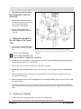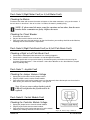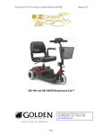
1
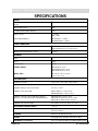
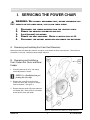
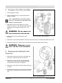
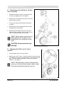
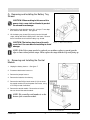
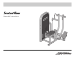
SERVICE MANUAL
Compass™ Service Manual
TABLE OF CONTENTS
WARRANTY ....................................................................................... 2
SPECIFICATIONS .................................................................................. 3
PREFACE ............................................................................................ 4
I. SERVICING THE POWER CHAIR ......................................................... 5
A.
B.
C.
D.
E.
F.
G.
H.
I.
J.
K.
Removing and Installing the H-bar Seat Receivers ................................................ 5
Removing and Installing a Front Caster Arm Cover and Rear Fender ................... 5
Changing a Drive Wheel and Motor ....................................................................... 6
Removing and Installing a Front Caster Arm ......................................................... 6
Removing and Installing a Fender-Fork Assembly ................................................. 7
Adjusting the Pitch on the Front Casters ................................................................. 7
Removing and Installing the Battery Tray Shroud .................................................. 8
Removing and Installing the Controller Module ..................................................... 8
Removing and Installing the Retractable Desk Arm Assembly ................................ 9
Moving the Joystick to the Left Side of the Power Chair ........................................ 9
Installing the Seatbelt............................................................................................... 9
II. TROUBLESHOOTING THE SHARK® CONTROLLER ........................... 10
Flash Code 1 ................................................................................................................ 10
Flash Code 2 ................................................................................................................ 10
Flash Code 2 Amber .................................................................................................... 10
Flash Code 3 or 4......................................................................................................... 11
Flash Code 5 or 6......................................................................................................... 11
Flash Code 7 ................................................................................................................ 11
Flash Code 8 ................................................................................................................ 11
Flash Code 9 ................................................................................................................ 12
Flash Code 10 .............................................................................................................. 12
Ph: (800) 624-6374
Fax: (800) 628-5165
www.goldentech.com
Golden Technologies, Inc.
401 Bridge Street
Old Forge, PA 18518
GP600-SM
1
RevA02062006
Compass™ Service Manual
WARRANTY
LIFETIME WARRANTY:
Power Chair Frame
Golden Technologies, Inc. will repair the frame with new or refurbished parts, free of charge in the USA, in the
event of defective materials or workmanship.
ONE-YEAR LIMITED WARRANTY:
Electronic Controller
Drive train components
Golden Technologies, Inc. will repair/replace these products with new or refurbished parts, free of charge in
the USA, for one year from the original date of purchase, in the event of defective materials or workmanship.
Note: The motor brushes are excluded from the one-year limited warranty.
WARRANTY EXCLUSIONS:
•
•
•
•
•
ABS Plastic Shrouds
Batteries (warranted by the manufacturer)
Tires and tubes
Labor, service calls, shipping, and other charges incurred in the repair of the product, unless
specifically authorized by Golden Technologies, Inc.
Labor charges incurred in replacement part installation
Implied warranties, including those of merchantability and fitness for a particular purpose, are excluded.
Liabilities for consequential damage are also excluded.
This warranty only covers failures due to defects in materials or workmanship which occur during normal use,
and does not cover damage that may incur in shipment or failures which are caused by products not supplied
by Golden Technologies, Inc., or failures resulting from accident, misuse, abuse, neglect, mishandling,
misapplication, alteration, modification, or by anyone other than an authorized Golden Technologies, Inc.
dealer, or damage that is attributable to acts of God.
This warranty is extended only to the original purchaser. The purchaser’s receipt will be necessary as proof
before any warranty performance is rendered. To obtain warranty parts and service, a warranty registration
card must be filed with Golden Technologies, Inc.
The warranty period commences on the purchase date from the seller/dealer. If the product is rented or
otherwise not sold to the consumer, the warranty commences on the invoice date from Golden Technologies,
Inc.
This warranty gives the user specific rights; the user may also have other rights that vary from state to state.
Golden Technologies, Inc. shall not be liable for incidental or consequential damage resulting from the
misuse of this product or arising out of any breach of this warranty.
GP600-SM
2
RevA 02062006
Compass™ Service Manual
SPECIFICATIONS
WEIGHT
Base: includes frame, motors, wheels, seat receivers, and
shrouds
88 lbs.
Armrests with joystick
14 lbs.
Seat with headrest (without armrests)
34 lbs.
Batteries (each)
U1 = 24 lbs.
NF22 = 39 lbs.
Total weight with batteries
With U1batteries = 184 lbs.
With NF22 batteries = 214 lbs.
OVERALL DIMENSIONS
Length
With standard footrest = 38 1/2 in.
With extended footrest = 41 1/2 in. to 43 in.
Width (measured from outsides of tires)
24 1/2 in.
MAXIMUMS
Incline
6°
Speed
5 mph
Load Capacity
300 lbs.
TURNING RADIUS
Without footrest = 15 in.
With standard footrest = 19 in.
With extended footrest = 22 in.
WHEEL SIZES
Drive wheels = 10 in. x 3 1/2 in.
Casters = 6 in. x 2 in.
SEAT DIMENSIONS
Standard seat cushion
18 in. x 18 in., 18 in. x 20 in., 20 in. x 20 in.
Adjustable armrest width (measured from outsides)
23 1/4 in. to 29 3/4 in.
Adjustable armrest-to-seat cushion height
8 in., 9 in., or 10 in.
Adjustable seat-to-floor height
With U1 batteries = 18 in. to 23 in.
With NF22 batteries = 20 in. to 23 in.
Adjustable seat back-to-floor height with U1 batteries
(Add 2 in. to each measurement if using NF22 batteries.)
Without headrest = 37 in. to 41 in.
With headrest unextended = 45 in. to 49 in.
With headrest extended = 50 in. to 54 in.
Adjustable footrest-to-floor height
5 in., 5 5/8 in., 6 1/4 in., 6 7/8 in., or 7 1/2 in.
ADJUSTABLE FOOTREST ANGLE
- 4° to 17°
CONTROLLERS
Integral OR Dynamic Shark; 60 amp programmable with
K10 or K11 lockout
CHARGER
Off board, 110 VAC 60 Hz 5 amp
COLORS
Candy Apple Red, Artic Blue, Hunter Green, Onyx
BATTERIES (recommended)
Two U1 (35 Ah) SLA, AGM, or Gel; OR two NF22 (55 Ah)
GP600-SM
3
RevA02062006
Compass™ Service Manual
PREFACE
This manual is intended to enhance, not replace, other materials provided by Golden Technologies, Inc.,
such as the Compass™ Owner’s Manual and the Shark® Owner’s Manual. As the product is changed,
updates to service procedures will be announced to you.
The following symbols will be used in this manual to indicate important information requiring your attention:
NOTE: Provides additional helpful information.
CAUTION: Contains information that, if not heeded, could result in minor injury
to the power chair or you.
WARNING: CONTAINS
INFORMATION THAT, IF NOT HEEDED, COULD RE-
SULT IN DAMAGE TO THE POWER CHAIR, VOID THE WARRANTY, AND/OR RESULT IN SEVERE INJURY OR POSSIBLY DEATH.
Refer to the Compass Owner’s Manual for the following information:
Battery Access
Battery Charging
Battery Removal/Installation
NOTE: If you are replacing U1 batteries with NF22 batteries, you must remove the battery
divider before installing the NF22 batteries and then install the larger battery cover.
Comfort Settings
Joystick Installation
Joystick Operation
EMI/RFI information
General safety information
Seat Removal/Installation
Thermal Rollback
CAUTION: Do not attempt to take apart any assemblies beyond what this
manual and the Compass Owner’s Manual describe. Doing so will void the
warranties and/or cause damage to the power chair and its components.
Serial Number Information:
The serial number is found under the footrest and signifies the date of manufacture.
GP600-SM
4
RevA 02062006
Compass™ Service Manual
I. SERVICING THE POWER CHAIR
WARNING: WE
STRONGLY RECOMMEND THAT, BEFORE PERFORMING ANY
SERVICE ON THE POWER CHAIR, YOU FOLLOW THESE STEPS:
1.
2.
3.
4.
5.
DISCONNECT THE JUMPER HARNESS FROM THE JOYSTICK CABLE.
REMOVE THE ARMREST ASSEMBLIES AND SEAT.
LOCK (ENGAGE) THE MOTORS.
REMOVE THE SEAT RECEIVERS. REFER TO INSTRUCTION SET A.
DISCONNECT THE BATTERY HARNESSES AND REMOVE THE BATTERIES.
A. Removing and Installing the H-bar Seat Receivers
Remove the four ball detent pins from the seat posts, and remove the H-bar seat receivers. Reverse these
instructions to reinstall, setting the correct height and pitch.
B. Removing and Installing a
Front Caster Arm Cover and Rear
Fender
1. Place the power chair on its side, being
careful to protect its surface.
NOTE: Use a flashlight when performing the next steps.
2. Remove the screw (B1) from the front
caster arm cover (B2), using a P1 Phillipshead screwdriver. See figure 1.
3. Remove the two screws (B3) from under the
rear fender (B4). Reverse these instructions
to reinstall the cover and fender.
Figure 1. Left Front Caster Arm Cover and Rear Fender
GP600-SM
5
RevA02062006
Compass™ Service Manual
C. Changing a Drive Wheel and Motor
1. Lock (engage) the motors.
2. Place the power chair on its side, being careful to
protect its surface.
Note: Performing the removals in instruction set A is not necessary, but makes wheel
and motor removal easier.
3. Remove the center nut and washer (C1) on the
wheel hub, using a 17-mm deep-dish socket wrench,
and pull off the drive wheel assembly (C2). See
figure 2.
WARNING: DO
NOT REMOVE THE
FOUR ACORN NUTS FROM THE HUB.
4. Remove the key (C3) from the keyway in the
transaxle.
Figure 2. Left Drive Wheel and Motor
5. Remove the six 5-mm Allen-head bolts (C4) that secure the transaxle assembly to the power chair frame.
6. Remove the motor (C5). Reverse these instructions to reinstall the motor and drive wheel.
WARNING: REMEMBER
TO REIN-
STALL THE KEY IN THE TRANSAXLE.
D. Removing and Installing the Front
Caster Arm
1. Remove the front caster arm cover, rear fender, and
drive wheel. Refer to instruction sets B and C.
2. Remove the 17-mm nut (D1) and corresponding
Phillips-head screw (D2) that hold the front caster
arm to the rear caster area. See figure 3.
3. Remove the snap ring (D3) from the lower front frame
assembly.
4. Slide the front caster arm out and off of the front frame.
Reverse these instructions to reinstall the front caster
arm.
Figure 3. Left Front Caster
GP600-SM
6
RevA 02062006
Compass™ Service Manual
E. Removing and Installing a FenderFork Assembly
1. Remove the weather cap (E1), on top of the fork
assembly, by popping it off. See figure 4.
2. Remove the 3-mm Allen-head screw (E2) from the
top of the fork assembly.
3. Lift up on the frame and remove the fender-fork
assembly.
4. Remove the nut (E4) and bolt (E5) from the fork,
and remove the caster wheel.
5. Remove the two Phillips-head screws (E6) that
hold the fender to the fork. Reverse these instructions to reinstall the fender-fork assembly.
NOTE: All four fenders are the same size.
When replacing the assembly, face the
duckbill to the rear (with the flow of the
fork).
CAUTION: Be sure to test for freewheeling.
Figure 4. Fender-Fork Assembly
F. Adjusting the Pitch on the Front
Casters
1. Place the power chair on a level surface.
2. Hold the jam nut (F1) with a 17-mm box wrench, and turn the bolt
(F2) clockwise, using a 5-mm Allen wrench, to raise (increase) the
pitch. To lower (decrease) the pitch, turn the screw counter
clockwise. See figure 5.
NOTE: The ideal setting is achieved when the front
casters are set 1/8 in. from the surface with no weight
in the chair (with batteries and seat removed).
Figure 5. Caster Wheel Adjustment
GP600-SM
7
RevA02062006
Compass™ Service Manual
G. Removing and Installing the Battery Tray
Shroud
CAUTION: When working in this area of the
power chair, use a cloth or blanket to protect
the shroud from damage.
1. Remove the circuit breaker cover (G1), using a 17-mm deep
dish socket or box wrench. See figure 6.
2. Lift the battery tray shroud (G2) evenly from the Velcro®
straps, taking note of the holding slots in the frame. Reverse
these instructions to reinstall the battery tray shroud.
CAUTION: The battery tray shroud is easily
scratched. Use care when reinstalling to avoid
damage.
Figure 6. Battery Tray Shrouds
NOTE: If the Velcro straps need to be replaced, use needlenose pliers to spread open the
clips to remove them from the straps. Then, replace the straps with the loop ends facing up.
H. Removing and Installing the Control
Module
1. Unplug the battery harness. See figure 7.
2. Disconnect both motor harnesses.
3. Remove the jumper harness.
4. Remove the batteries from the tray.
5. Remove the two Phillips-head screws (H1) that secure
the control module (H2) to the power chair frame, using
a P2 Phillips-head screwdriver.
6. Remove the control module. Reverse these instructions to reinstall the control module.
NOTE: The controller serial number is on the
bottom of the controller module.
Figure 7. Control Module
GP600-SM
8
RevA 02062006
Compass™ Service Manual
I. Removing and Installing
the Retractable Desk Arm
Assembly
1. Remove the retractable desk arm
assembly from the receiver bracket
(I1) by loosening the 4-mm
setscrew (I2). See figure 8.
2. Reverse these instructions to
reinstall the retractable desk arm
assembly.
J. Moving the Joystick to
the Left Side of the Power
Chair
1. Remove the right retractable desk
arm assembly. Refer to instruction
set I.
Figure 8. Retractable Desk Arm Assembly (Note: Entire assembly
broken down for clarification. Only remove/install parts labeled with
callouts.)
Note: You will need to
order a left retractable desk
arm assembly to complete this installation.
2. Remove the receiver bracket (I1) from under the right armrest by uninstalling the two Allen-head screws
and 5-mm lock washers (J1). See figure 8.
3. Reinstall the armrest receiver bracket (I1) to left armrest assembly.
4. Remove the two 3-mm button-head screws (J2) and 5/16-in. nuts (J3) from the joystick mounting plate
(J4).
5. Remove the joystick (J5) from the joystick mounting plate by uninstalling the 4-mm Allen-head screws
(J6) underneath the plate.
6. Attach the joystick to the new left retractable desk arm assembly, following steps 5 and 4 in reverse, with
the same hardware.
7. Reattach the retractable desk arm assembly to the armrest receiver bracket, connecting the additional
12-in. length of harness to the joystick cable and current jumper harness to compensate for the extra distance.
K. Installing the Seatbelt
1. Remove the armrest adjustment knobs at the rear of the power chair.
2. Insert the knob stem through the hole at the end of each seatbelt, and reinstall the knobs.
GP600-SM
9
RevA02062006
Compass™ Service Manual
II. TROUBLESHOOTING ELECTRONICS
AND THE SHARK® CONTROLLER
Note: The Dynamic® control module can be mounted on either side of the power chair
frame, in an upright position, using M5 screws. These should be tightened to a torque of
approximately 2 Newton meters (1816 lb.-in.).
NOTE: Batteries must have at least 18 VDC (combined) for the Shark system to operate. If
they do not, charge the batteries and perform a load test.
The following instructions provide details on diagnosing flash codes, in addition to the information provided in
the Shark manual:
Flash Code 1: Possible Stall Timeout or User Fault
Release the joystick to neutral and try operating the power chair again.
Flash Code 2: Battery Fault
Ensure that the battery cables are installed correctly per the owner’s manual. Check for source voltage.
Flash Code 2 Amber: Over- or Under-voltage Fault
Checking the Voltage
Check the battery voltage. If the batteries are producing between less than 13 VDC, charge them and
perform a load test.
Checking the Battery Charger
1. Unplug the joystick cable from the jumper harness.
2. Plug the charger into the joystick.
3. Take a voltage reading from the top two pins at
the end of the joystick cable; your reading
should be 27-29 VDC. See figure A.
Figure A. Top and End of Joystick Cable
GP600-SM
10
RevA 02062006
Compass™ Service Manual
Flash Code 3 (Right Motor Fault) or 4 (Left Motor Fault):
Checking the Motors
Disconnect the motor and measure the motor resistances at the motor connectors, using an ohm meter. If
the resistance is more than 1 ohm or less than 1 milliohm, the motor is probably faulty.
NOTE: If, when rotated, the motor seems fine sometimes and not others, then the motor
brushes and/or commutator are faulty. Replace the motor.
Checking the Circuit Breaker
1. Disconnect both batteries.
2. Set your ohm meter to the base unit of ohms.
3. Place your lead across the two terminals on the circuit breaker; your reading should be under 20 ohms,
indicating that the circuit breaker is operational.
Flash Code 5 (Right Park Break Fault) or 6 (Left Park Break Fault):
Checking a Right or Left Park Break Fault
1. Check that the motor/park brake connectors are securely plugged in.
2. Check that the contacts in the connectors are not damaged or corroded.
3. Check the park brakes using an ohm meter by disconnecting each park brake and measuring the
resistance at the connectors. If the resistance is more than 100 ohms or less than 20 ohms, the park
brake is probably faulty.
Flash Code 7: Joystick Fault
Checking the Jumper Harness Voltage
1. Unplug the joystick cable from the jumper harness.
2. Plug the jumper harness into the control module.
3. Place ohm meter leads into the jumper harness at the open end, where the two pins are closest to the
down arrow; you should see source voltage. See figure B.
Note: If you see source voltage but the joystick’s
LEDs do not light, then the joystick needs to be
replaced.
Flash Code 8: Control Module Fault
Checking the Controller Module Voltage
1. Unplug the jumper harness from the control module.
2. Plug the joystick cable into the control module.
3. Place ohm meter leads into the two outer pins on the control
module; your reading should be 24 volts or more.
GP600-SM
11
Figure B. End of Jumper Harness
RevA02062006
Compass™ Service Manual
Flash Code 9: Communications Fault
Check the connections and wiring; replace the joystick.
Flash Code 10: Unknown Fault
Check the connections and wiring; consult a service agent.
NOTES:
GP600-SM
12
RevA 02062006