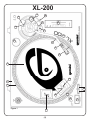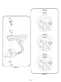
1
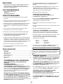
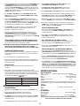
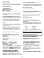
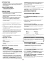
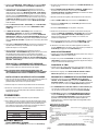
OPERATIONS MANUAL
BEDIENUNGSHANDBUCH
MANUAL DEL OPERADOR
MANUEL D’INSTRUCTIONS
XL-200
BELT-DRIVE MANUAL TURNTABLE
MANUELLER PLATTENSPIELER MIT RIEMENANTRIEB
GIRADISCOS MANUAL ACCIONADO POR CORREA
TABLE TOURNANTE MANUELLE ENTRAÎNÉE PAR COURROIE
MULTI LANGUAGE INSTRUCTIONS:
English...............................................................................................................Page 4
Deutsch.............................................................................................................Page 6
Español..............................................................................................................Page 8
Francais..........................................................................................................Page 10
(1)
XL-200
13
18
9
9
20
12
11
19
6
8
6
5
4a
1
2
14
4b
16
15
Figure 1
21
3
(2)
17
Figure 2
Figure 3
(3)
INTRODUCTION:
TURNTABLE INSTALLATION:
1. Put the SLIPMAT (5) on the PLATTER (2).
Congratulations on purchasing a Gemini XL-200 turntable. This state of
the art turntable includes the latest features. Prior to use, we suggest that
you carefully read all the instructions.
2. Set the TURNTABLE BASE (1) on a flat, level surface free of vibration.
Use the turntable feet to horizontally stabilize the unit.
FEATURES
3. Try to place the unit as far away from the speakers as possible.
• ±10% Pitch control:
• Strobe illuminator
• Soft-touch start/stop switch
4. Keep the unit away from direct exposure to the sun, heat, moisture or dirt.
5. Keep the unit well ventilated.
PRECAUTIONS:
CARTRIDGE INSTALLATION: (SEE FIG. 2)
1. Read all operating instructions before using this equipment.
Because all cartridges have their own designs, please refer to your
particular cartridge’s instructions to insure proper installation.
2. The apparatus should not be exposed to dripping or splashing, and no
objects filled with liquids such as vases should be placed on the apparatus.
1. Connect the lead wires to the cartridge terminals. For your convenience,
the terminals of most cartridges are color coded. Connect each lead wire
to the terminal of the same color.
3. To reduce the risk of electrical shock, do not open the unit. There are
NO USER REPLACEABLE PARTS INSIDE. Please contact the Gemini
Service Department or your authorized dealer to speak to a qualified
service technician.
White (L+).................Left Channel +
Blue (L-)...................Left Channel Red (R+)....................Right Channel +
Green (R-).................Right Channel -
4. Tone Arm bearings are factory set and sealed. Any attempt at adjustment
will void the warranty.
2. Mount the cartridge in the HEADSHELL (6) and tighten it with the screws
included with the cartridge.
5. Be sure that all AC power is OFF while making connections.
6. Cables should be low capacitance, shielded and of proper length. Make
sure that all plugs and jacks are tight and properly connected.
ATTENTION STANTON 680 CARTRIDGE USERS
When using a Stanton 680 or similar cartridge, where the body is
grounded to a cartridge terminal, remove the grounding strap from the
cartridge body to the cartridge ground terminal. Failure to do this may
result in excessive hum.
7. Always begin with the audio level faders/volume controls set at minimum
and the speaker volume control(s) set to OFF. Wait 8 to 10 seconds prior
to turning up the speaker volume to prevent the transient “POP” that
could result in speaker/crossover damage.
HEADSHELL INSTALLATION:
Insert the HEADSHELL (6) into the front of the tubular TONE ARM (7). While
holding the HEADSHELL firmly in a horizontal position, turn the LOCKING NUT
(8) counter clockwise until the HEADSHELL is locked in place.
8. DO NOT EXPOSE THIS UNIT TO RAIN OR MOISTURE.
9. DO NOT USE ANY SPRAY CLEANER OR LUBRICANT ON ANY
CONTROLS OR SWITCHES.
COUNTERWEIGHT INSTALLATION: (SEE FIG. 3)
PARTS CHECKLIST:
Turntable unit...............................................................................................1
Dust cover hinge..........................................................................................2
Turntable platter...........................................................................................1
45 RPM adapter...........................................................................................1
Slipmat.........................................................................................................1
Counter balance..........................................................................................1
Dust cover....................................................................................................1
Headshell.....................................................................................................1
ASSEMBLY AND SET-UP:
1. Slide the COUNTERWEIGHT (9) onto the rear of the TONE ARM (7)
with the numbered stylus gauge facing forward.
2. Twist the COUNTERWEIGHT (9) lightly counter clockwise, to screw it
onto the rear of the TONE ARM (7) .
ADJUSTING HORIZONTAL ZERO (0) BALANCE AND
STYLUS PRESSURE:
1. Without touching the stylus tip, remove the stylus protector (if your
cartridge has a detachable one).
2. Release the ARM CLAMP (10) and lift the TONE ARM (7) off the ARM
REST (11).
NOTE: SEE FIG. 1 FOR PART NUMBERS AND LOCATIONS.
VOLTAGE SELECTION:
3. Counter clockwise advancement of the COUNTERWEIGHT (9) will
cause the cartridge side of the TONE ARM (7) to be lowered. Clockwise
will cause the opposite. Turn the COUNTERWEIGHT clockwise or
counter clockwise as needed until the TONE ARM is balanced
horizontally. You can easily tell this by watching for the point where the
TONE ARM “floats” freely.
Rotate the PLATTER (2) until the VOLTAGE SELECTOR (3) (located on
the TURNTABLE BASE (1)) is visible through one of the platter holes.
Make sure that the VOLTAGE SELECTOR switch is set to the correct
voltage. WARNING: If you try to operate the turntable with the incorrect
voltage setting, it can damage your turntable.
ATTACHING THE TURNTABLE BELT:
4. Place TONE ARM (7) on ARM REST (11) and lock it in place with the
ARM CLAMP (10).
The TURNTABLE BELT (4A) comes attached to the PLATTER (2) and
the MOTOR SPINDLE (4B) but can some times detach in shipping.
Rotate the PLATTER (2) and look through the platter holes to check if belt
detached. If the belt is not wrapped tightly around the platter and the
MOTOR SPINDLE, you need to reattach it.
5. With the TONE ARM (7) locked on the ARM REST (11), hold the
COUNTERWEIGHT (9) steady with one hand while rotating the STYLUS
PRESSURE RING (12) until the numeral “0” on the ring aligns with the
center line on the TONE ARM rear shaft. The horizontal zero (0) balance
should be completed.
1. Remove the platter and wrap the belt around the inner circle under the
platter. DO NOT STRETCH OUT THE BELT.
2. Replace the platter and rotate the PLATTER (2) until the MOTOR SPINDLE
(4B) is visible, then fit your fingers in hole on the top of the PLATTER (2), feel for
and grab the rubber belt and attach to the motor spindle.
6. Refloat the TONE ARM to ensure horizontal zero (0) balance. If zero
balance has not been maintained, repeat counterweight steps 3 - 5.
3. Replace the locking washer.
(4)
PLAYING 45 RPM RECORDS:
7. After adjusting the horizontal zero (0) balance, turn the balanced
COUNTERWEIGHT (9) counter clockwise until the cartridge
manufacturer’s recommend stylus pressure appears on the STYLUS
PRESSURE RING (12) where it meets the center line of the TONE ARM
(7) rear shaft.
1. When playing a 45 RPM record with a large center hole, first place the
45 ADAPTER (19) on the center spindle.
2. Be sure that the 45 SPEED SELECTOR (14) button is pushed and the
45 speed indicator is illuminated.
ADJUSTING THE ANTI-SKATING CONTROL:
Set the ANTI-SKATING CONTROL (13) to the same value as the stylus
pressure.
ADJUSTING THE PITCH CONTROL:
NOTE: IF YOUR TURNTABLE CAME WITH A CN-25 CARTRIDGE, IT HAS
A RECOMMENED TRACKING FORCE OF 3.0 GRAMS AND CAN HAVE
RANGE FROM 2.5-3.5 GRAMS.
INSTALLING THE DUSTCOVER:
1. Hold the dustcover in position, directly above the turntable, and slide the
hinge bases into the holders mounted on the rear panel.
2. Always raise the dustcover before removal.
3. Avoid opening and closing the dustcover during play. Undesirable
vibration and stylus skipping can result.
CONNECTIONS:
1. Plug the AC power plug into an appropriate outlet.
2. See Table A for proper connection of the output RCA plugs and ground
connector. Make sure that all the plugs are firmly plugged into the
appropriate jacks (phono inputs). To reduce hum, make sure the ground
lug is firmly connected to the ground screw.
TABLE A
OUTPUT CONNECTORS
L (WHITE)
MIXER OR RECEIVER
R (RED)
PHONO R CHANNEL
GND (Spade Lug)
GND Screw
PHONO L CHANNEL
OPERATING INSTRUCTIONS:
BASIC OPERATION:
1. Place a record on the SLIPMAT (5) which sits on the PLATTER (2).
1. The XL-200 is equipped with a PITCH CONTROL (20). When the PITCH
CONTROL is in the center position the speed will be 33 or 45 depending
on which SPEED SELECTOR (14) button is pushed.
2. When the PITCH CONTROL (20) is positioned off center, the pitch can
vary ±10% depending on the position of the PITCH CONTROL.
3. The PLATTER (2) is equipped with a STROBE RPM INDICATOR STRIP
(21). When the PLATTER (2) is spinning, the STROBE LIGHTS (16)
illuminate the STROBE RPM INDICATOR STRIP. At 60 Hz the bottom
row of dots will appear to be stationary when the speed of the platter is
exactly 45 RPM and the second row from the bottom will appear to be
stationary at 33 RPM. At 50 Hz, the second row from the top represents
45 RPM and the top row represents 33 RPM.
SPECIFICATIONS:
TURNTABLE SECTION:
Type.......................................................................Belt Drive Manual Turntable
Drive Method.......................................................................................Belt Drive
Motor...................................................................................................DC Motor
Speed.....................................................................................33 1/3 or 45 RPM
Wow and Flutter.........................................................Less than 0.25% WRMS*
* This rating refers to the turntable assembly and platter only and excludes
effects of records, cartridges or tonearms.
TONEARM SECTION:
Type.....................................................Statically Balanced S-Shaped Tonearm
Headshell Weight.......................................................................................5.6 g
GENERAL:
Power Supply.................................................................115V 60Hz/230V 50Hz
Power Consumption...............................................................................5 Watts
Dimensions.....................................17.75" x 5.75" x 14" (450 x 146 x 352 mm)
Weight.........................................................................................8 lbs. (3.75 kg)
SPECIFICATIONS ARE SUBJECT TO CHANGE WITHOUT NOTICE.
THE WEIGHT AND DIMENSIONS SHOWN ARE APPROXIMATE.
2. Select the desired speed by depressing the 33 or 45 SPEED
SELECTOR (14) button.
3. Turn the POWER (15) switch to the “ON” position, at which point the
STROBE LIGHTS (16) and the speed indicator (for the selected speed)
will illuminate.
4. Remove the stylus protector (if applicable to your cartridge).
5. Release the ARM CLAMP (10) found on the ARM REST (11).
6. Push the START/STOP (17) button. The turntable PLATTER (2) will start
to spin.
7. Push the CUE LEVER (18) to the “UP” position.
8. Position the tone arm over the desired position on the record and push
the CUE LEVER to the “DOWN” position. The TONE ARM (7) will
slowly lower onto the record at which time play will begin.
9. When play is over, raise the TONE ARM, move it to the ARM REST, and
secure it with the ARM CLAMP.
10.You now have the option of turning off the power by turning the POWER
(15) switch to the “OFF” position, or stopping the PLATTER (2) by
pushing the START/STOP (17) button.
INTERRUPTING PLAY:
1. Pushing the CUE LEVER (18) to the “UP” position will cause the TONE
ARM (7) to lift stopping play.
2. Pushing the CUE LEVER (18) to the “DOWN” position will cause the
TONE ARM (7) to slowly lower onto the record at the point where play
was interrupted.
(5)
EINLEITUNG:
1. Das Plattentellerchassis abnehmen, und den Riemen um den inneren
Ring unter das Plattentellerchassis legen. DEN RIEMEN NICHT
DEHNEN.
Wir gratulieren Ihnen zum Kauf eines Gemini XL-200 Plattenspielers.
Dieses hochentwickelte erstklassige Gerät enthält die neuesten
Leistungsmerkmale. Vor Anwendung dieses Plattenspielers bitte alle
Anweisungen sorgfältig durchlesen.
2. Den PLATTENTELLER - PLATTER (2) aufsetzen und drehen, bis die
Motorwelle sichtbar ist, dann die Finger in das Loch am oberen
Plattentellerrand einführen und nach dem Gummiriemen tasten, diesen
ergreifen und dann auf der Motorwelle anbringen.
LEISTUNGSMERKMALE
• ± 10% Tonhöhenabstimmung
• Strobelicht
• Start-/Stop-Funktionstaste
3. Sie Sicherungsscheibe wieder einsetzen.
EINBAU DES PLATTENSPIELERS:
1. Den PLATTENTELLERAUFLAGE - SLIPMAT (5) auf den
PLATTENTELLER - PLATTER (2) legen.
VORSICHTSMANAHMEN
1. Vor Anwendung dieses Geräts bitten alle Anweisungen sorgfältig
durchlesen.
2. Setzen Sie das PLATTENSPIELERCHASSIS - TURNTABLE BASE (1)
auf eine flache, ebene Fläche ohne Vibration. Es mit den
Plattentellerfüßen horizontal lagefest machen.
2. Das Gerät vor Tropfen und Spritzern schützen, und es dürfen keine mit
Flüssigkeit gefüllte Behälter wie Vasen darauf gestellt werden.
3. Das Gerät so weit wie möglich von den Lautsprechern entfernt
aufstellen.
3. Das Gerät nicht öffnen, um das Risiko elektrischen Schocks zu mindern.
Es enthält KEINE VOM ANWENDER ERSETZBAREN TEILE. Die
Wartung darf nur von befähigten Wartungstechnikern durchgeführt
werden.
4. Das Gerät von direktem Sonnenlicht, Wärme, Feuchtigkeit oder Schmutz
fernhalten.
4. Die Tonarmlager sind werkseingestellt und abgedichtet. Jegliche
Änderungsversuche machen die Garantie ungültig.
5. Das Gerät in gut belüfteter Umgebung aufstellen.
EINBAU DES TONABNEHMERS: (SIEHE ABBILDUNG 2)
5. Darauf achten, da beim Anschlu die Wechseltromleistung abgeschaltet ist.
Weil alle Tonabnehmer individuell ausgeführt sind, siehe jeweilige
Anweisungen für Tonabnehmer, um richtigen Einbau sicherzustellen.
6. Nur kapazitätsarme, abgeschirmte Kabel vorschriftsmäiger Länge
benutzen. Darauf achten, da alle Stecker und Buchsen fest
angeschraubt und richtig angeschlossen sind.
1. Die Zuleitungsdrähte an den Tonabnehmerklemmen anschlieen. Um den
Anschlu zu erleichtern, sind die meisten Tonabnehmerklemmen
farbkodiert. Die Zuleitungsdrähte an den Klemmen der jeweiligen
Farbkennzeichnung anschlieen.
7. Zu Beginn müssen die Tonpegelüberblender und Lautstärkenregler auf
Mindeststärke eingestellt und der (die) Lautstärkenregler in OFF-Position
geschaltet sein. Vor dem Lauterstellen 8 bis 10 Sekunden warten, um
den durch Einschwingung erzeugten Schroteffekt zu vermeiden, welches
zu Lautsprecher- und Frequenzweichenschaden führen könnte.
Weiß (L+)...................linker Kanal +
Blau (L-)....................linker Kanal Rot (R+)........................rechter Kanal +
Grün (R-)....................rechter Kanal -
8. Dieses Gerät nicht Regen oder Feuchtigkeit aussetzen.
2. Den Tonabnehmer in den TONKOPF - HEADSHELL (6) einbauen und
mit den dem Tonabnehmer beigefügten Schrauben befestigen.
9. An den Reglern oder Schaltern kein Spray-Reinigungsmittel oder
Schmiermittel benutzen.
WICHTIG FÜR ALLE ANWENDER DES STANTON 680 TONABNEHMERS
Bei Anwendung eines Stanton oder ähnlichen Tonabnehmer, wo der
Körper an einer Tonabnehmerklemme geerdet ist, den Erdungsdraht
entfernen, der vom Körper des Tonabnehmers zur Erdungsklemme führt.
Nichtbeachtung dieser Manahme kann zu übermäigem Brummen
führen.
TEILE-CHECKLIST:
Plattenspieler...............................................................................................1
Plattenteller..................................................................................................1
Plattentellerauflage......................................................................................1
Abdeckhaube...............................................................................................1
Abdeckhaubenscharnier..............................................................................2
45-U/min-Adapter........................................................................................1
Balancegewicht...........................................................................................1
Tonkopf........................................................................................................1
EINBAU DES TONKOPFES:
Den TONKOPF - HEADSHELL (6) in der Vorderseite des röhrenförmigen
TONARMS - TONE ARM (7) einfügen. Beim Halten des TONKOPFES in
horizontaler Position die SICHERUNGSMUTTER - LOCKING NUT (8)
gegen den Uhrzeigersinn drehen, bis der TONKOPF einrastet.
ZUSAMMENBAU UND ANORDNUNG:
HINWEIS: SIEHE ABBILDUNG 1 FüR TEILENUMMERN UND
POSITIONEN.
SPANNUNGSAUSWAHL:
Den PLATTENTELLER - PLATTER (2) rotieren bis den
SPANNUNGSWAHLER - VOLTAGE SELECTOR (3) (befindet sich auf
dem PLATTENSPIELERCHASSIS - TURNTABLE BASE (1)) sichtbar ist
durch ein Loch des Plattentellers. Den VOLTAGE SELECTOR (3) auf der
richtigen Spannung setzen. WARNUNG: Lassen Sie den PLATTER
rotieren mit einer falschen Spannungseinstellung, dann kann der
Plattenspieler sich beschädigen.
WIE MAN DEN PLATTENTELLERRIEMEN ANBRINGT:
Der RIEMEN - TURNTABLE BELT (4A) wird am unteren Ende des PLATTER
(2) und der MOTORWELLE - MOTOR SPINDLE (4B) befestigt geliefert, kann
sich manchmal aber beim Versand lösen. Den PLATTER drehen und durch die
Löcher im Plattentellerchassis blicken, um nachzuprüfen, ob der Riemen
angebracht ist. Wenn der Riemen nicht fest um das Plattentellerchassis und die
MOTORWELLE angelegt ist, muß er neu angelegt werden.
EINBAU DES BALANCEGEWICHTS: (SIEHE ABBILDUNG 3)
1. Das BALANCEGEWICHT - COUNTERWEIGHT (9) auf den hinteren Teil
des TONARMS - TONE ARM (7) Schieben, wobei die numerierte
Nadeldicke nach vorne gerichtet sein muss.
2. Das COUNTERWEIGHT (9) gering im Gegenuhrzeigersinn ziehen, um es
auf den hinteren Teil des TONARMS - TONE ARM (7) zu schrauben.
HORIZONTALER NULLPUNKTABGLEICH UND
REGULIERUNG DES AUFLAGEDRUCKS:
1. Ohne die Nadelspitze zu berühren, entfernen Sie den Nadelschutz (falls
Ihr Tonabnehmer einen abnehmbaren Nadelschutz hat).
2. Die TONARM-KLEMMSCHELLE - ARM CLAMP (10) freigeben und den
TONARM - TONE ARM (7) von der TONARMAUFLAGE - ARM REST
(11) abheben.
(6)
3. Durch das Verdrehen gegen den Uhrzeigersinn des ALANCEGEWICHTS
- COUNTERWEIGHT (9) wird die Tonabnehmerseite des TONARMS TONE ARM (7) gesenkt. Beim Drehen im Uhrzeigersinn geschieht das
Gegenteil. Das BALANCEGEWICHT je nach Bedarf im oder gegen den
Uhrzeigersinn drehen, bis der TONARM horizontal ausbalanciert ist. Dies
lässt sich leicht feststellen, indem man die Stelle beobachtet, wo der
TONARM unbehindert “schwimmt”.
5. Die TONARM-KLEMMSCHELLE - ARM CLAMP (10) an der
TONARMAUFLAGE - ARM REST (11) freigeben.
4. Den TONARM - TONE ARM (7) auf die TONARMAUFLAGE - ARM
REST (11) setzen und ihn mit der TONARM-KLEMMSCHELLE - ARM
CLAMP (10) festklemmen.
8. Den Tonarm über die gewünschte Rille auf der Platte positionieren, und den
CUE LEVER in die “DOWN”-Position schieben. Der TONE ARM (7) wird sich
langsam auf die Platte senken, woraufhin die Platte zu spielen beginnt.
5. Indem der TONE ARM (7) auf der ARM REST (11) festgeklemmt ist,
halten Sie das COUNTERWEIGHT (9) ruhig mit der Hand, während Sie
den STYLUS PRESSURE RING (12) rotieren, bis sich die Ziffer “0” auf
dem Ring mit der Mittellinie an der Hinterwelle des TONARMS ausrichtet.
Der horizontale Nullpunktabgleich (0) ist nun abgeschlossen.
9. Bei Beendigung des Spielens heben Sie den TONE ARM (7), schieben
ihn auf die ARM REST (11) und befestigen ihn mit der ARM CLAMP (10).
6. Die START STOP-TASTE - START/STOP (17) drücken. Der
PLATTENTELLER - PLATTER (2) wird anfangen zu drehen.
7. Den CUEING-HEBEL - CUE LEVER (18) in die “UP”-Position schieben.
10.Nun haben Sie die Option, den Strom abzuschalten, indem Sie den
POWER (15) in die “OFF”-Position schalten, oder den PLATTER (2) zu
stoppen, indem Sie die START/STOP (17).
6. Den TONARM erneut schwimmen lassen, um sicherzustellen, da der
horizontale Nullpunktabgleich (0) beibehalten wird. Wird er nicht
beibehalten, wiederholen Sie Schritte 3 - 5.
SPIELUNTERBRECHUNG:
7. Nach dem horizontalen NULLPUNKTABGLEICH das abgeglichene
COUNTERWEIGHT (9) gegen den Uhrzeigersinn drehen, bis der vom
Tonabnehmerhersteller empfohlene Auflagedruck auf dem STYLUS
PRESSURE RING (12) erscheint, wo er mit der Mittellinie des TONE ARM
(7) zusammentrifft.
1. Durch das Schieben des CUEING-HEBELS - CUE LEVER (18) in die
“UP”-Position wird der TONARM - TONE ARM (7) angehoben und
unterbricht das Spielen.
2. Das Schieben des CUE LEVER in die “DOWN”-Position wird den
TONE ARM (7) langsam an der Stelle auf die Platte setzen, wo das
Spielen unterbrochen wurde.
REGULIERUNG DER ANTISKATING-VORRICHTUNG:
DAS SPIELEN VON 45-U/MIN-PLATTEN:
Die ANTISKATING-VORRICHTUNG - ANTI-SKATING CONTROL (13)
auf den gleichen Wert wie den Auflagedruck einstellen.
1. Wenn Sie eine 45-U/min-Platte spielen, die ein groß Mittelloch hat,
setzen Sie zunächst einen 45 ADAPTER (19) auf die Spindel.
ANMERKUNG: WENN IHRE DREHSCHEIBE MIT EINER PATRONE CN-25
KAM, HAT SIE EIN RECOMMENED, KRAFT VON 3,0 GRAMM
AUFZUSPÜREN UND KANN STRECKE VON 2,5-3,5 GRAMM HABEN.
2. Darauf achten, da die SPEED SELECTOR (14) gedrückt ist und die 45-U/
min-drehzahlanzeige aufleuchtet.
REGULIERUNG DER TONHÖHENABSTIMMUNG:
EINBAU DER ABDECKHAUBE:
1. Der XL-200 ist mit einem PITCH CONTROL (20) ausgerüstet. Wenn der
TONHÖHENREGLER in Mittenposition steht, liegt die Drehzahl in der Nähe von
33 oder 45 U/min, je nachdem welche SPEED SELECTOR (14) gedrückt wird.
1. Halten Sie die Abdeckhaube direkt über dem Plattenteller in Position und
schieben die Scharniersockel in die Halterungen, die in die Rückwand
montiert sind.
2. Wenn der TONHÖHENREGLER - PITCH CONTROL (20) auerhalb der
Mittenposition steht, kann die Drehzahl zwischen +/-10% schwanken,
abhängig von der Position des TONHÖHENREGLERS.
2. Vor dem Entfernen immer die Abdeckhaube anheben.
3. Es sollte vermieden werden, die Abdeckhaube während des Spielens zu
öffnen und zu schlieen. Dies könnte zu unerwünschten Vibrationen und
Nadelspringen führen.
3. Der PLATTER (2) ist mit einem STROBE RPM INDICATOR STRIP (21)
ausgerüstet. Wenn sich der PLATTER (2) dreht, erleuchten die STROBE
LIGHTS (16) den STROBELICHT-U/MIN-ANZEIGESTREIFEN. Bei 230V/
50Hz wird die zweite Punktereihe von oben feststehend erscheinen, wenn
die Drehzahl genau 45 U/min ist. Die oberste Punktereihe wird bei einer
genauen Drehzahl von 33 U/min feststehend erscheinen.
ANSCHLÜSSE:
1. Den Gleichstromleistungsstecker an einer geeigneten Buchse
anschlieen.
2. Siehe Tabelle A für vorschriftsmä ige Anschlüsse der AusgangsRCAStecker und des Erdungssteckers. Achten Sie darauf, da alle Stecker
an den richtigen Buchsen fest angeschlossen sind (Phono-Eingänge).
Um Brummtöne zu vermindern, ist darauf zu achten, da die Erdungsöse
fest an der Erdungsschraube angeschlossen ist.
TABELLE A
AUSGANGSANSCHLUSS
MIXER ODER RECEIVER
L ( WEIß)
PHONO- L KANAL
R (ROT)
PHONO- R KANAL
ERDUNG (Flachöse)
Erdungsschraube
BEDIENUNGSANWEISUNGEN:
GRUNDBETRIEB:
1. Die Platte auf den SLIPMAT (5) legen, die auf dem PLATTER (2) sitzt.
2. Die gewünschte Drehzahl auswählen, indem Sie an der
SPEED SELECTOR (14) entweder 33 oder 45 auswählen.
3. Den POWER (15) in die “ON”-Position schalten, woraufhin die STROBE
LIGHTS (16) und die Drehzahlanzeige (für die ausgewählte Drehzahl)
aufleuchten werden.
SPEZIFIKATIONEN:
PLATTENSPIELER:
Typ....................................Manueller Plattenspieler mit Riemenantrieb
Antriebsmethode...........................................................................Riemenantrieb
Motor...............................................................................DC Gleichstrommotor
Drehzahl...........................................................................33 1/3 oder 45 U/min
Tonhöhenschwankungen............................................................0,25%
WRMS*
* Dieser Nennwert bezieht sich nur auf die Plattenspielermontage und auf
den Plattenteller, ausschielich Auswirkungen der Platten, Tonabnehmer oder
Tonarme.
TONARM:
Typ.........................................................S-förmiger statisch balanzierter
Tonarm
Tonkopfgewicht.........................................................................................5,6 g
ALLGEMEINES:
Stromversorgung........................................................115V 60Hz/230V 50Hz
Stromverbrauch........................................................................................5 W
Abmessungen............................................................450 x 146 x 352 mm
Gewicht...........................................................................................3.75 kg
SPEZIFIKATIONEN KÖNNEN OHNE VORHERIGE ANMELDUNG GEÄNDERT WERDEN.
GEWICHTSANGABEN UND ABMESSUNGEN SIND ANNÄHERND.
4. Den Nadelschutz abnehmen (falls an Ihrem Tonabnehmer vorhanden).
(7)
INTRODUCCIÓN:
1. Quite el plato y envuelva la correa alrededor del círculo interior debajo
del plato. NO HAGA EXTENDER LA CORREA.
Felicitaciones por su compra de un tocadiscos Gemini XL-200. Este
tocadiscos de la más avanzada tecnología está dotado de características
ultramodernas. Antes de usarlo, le recomendamos leer cuidadosamente
todas las instrucciones.
2. Reponga el plato y haga girar el PLATO - PLATTER (2) hasta que se
vea el eje del motor; entonces, ponga los dedos en el orificio en la parte
superior del PLATO, busque y agarre la correa de caucho y asegúrela al
eje del motor.
CARACTERÍSTICAS:
3. Reponga la arandela de seguridad.
• Regulación del tono de ±10%
• Iluminador estroboscópico
• Interruptor táctil de arranque/parada
INSTALACION DEL TOCADISCO:
1. Coloque la PATINADOR - SLIPMAT (5) sobre el PLATO.
PRECAUCIONES:
1. Deberán leerse todas las instrucciones de operación antes de usar el equipo.
2. Ponga la BASE DEL TOCADISCO - TURNTABLE BASE (1) sobre una
superficie plana y nivelada sin vibraciones. Use las patas del tocadisco
para estabilizar la unidad en sentido horizontal.
2. Este aparato no debería estar expuesto al goteo o a las salpicaduras y
ningun objeto lleno de líquido, tal como floreros, debería estar colocado
sobre el aparato.
3. Trate de colocar la unidad lo más lejos posible de los altoparlantes.
3. Para reducir el riesgo de shock eléctrico, no abra la unidad.
NO CONTIENE PIEZAS REEMPLAZABLES POR EL USUARIO. Sírvase
comunicarse con el Departamento de Servicio Gemini o su distribuidor
autorizado y hablar con un técnico de servicio calificado.
4. Mantenga la unidad alejada de la exposición directa del sol, calor,
humedad o suciedad.
5. Mantenga la unidad bien ventilada.
INSTALACIÓN DEL CARTUCHO: (VÉASE LA FIG. 2)
4. Los cojinetes del brazo de fonocaptor están ajustados y sellados en
fábrica. Cualquier intento de ajuste dejará sin efecto la garantía.
Debido a que todos los cartuchos son de diseño distinto, sírvase referirse
a las instrucciones de su cartucho específico, para garantizar la
instalación correcta.
5. Cerciórese de que toda la corriente CA esté APAGADA para efectuar las
conexiones.
1. Conecte los alambres conductores a los terminales del cartucho. Para
su conveniencia, los terminales de la mayoría de los cartuchos están
codificados por colores. Conecte cada alambre conductor al terminal del
mismo color.
6. Los cables deberán ser de baja capacidad, reguardados, y de apropiado
longitud. Cerciórese de que todos los enchufes y jacks estén apretados
y debidamente conectados.
Blanco (I+).............................Canal izquierdo +
Azul (I-)................................Canal izquierdo Rojo (D+)...............................Canal derecho +
Verde (D-)...............................Canal derecho -
7. Comience siempre con los atenuadores de nivel de audio/control de
volumen fijados en el nivel mínimo y el control de volumen de los
altoparlantes fijados en APAGADO. Espere 8 a 10 segundos antes de
aumentar el volumen de los altoparlantes para evitar el “chasquido”
transitorio que podría ocasionar daños a los altoparlantes/de cruce.
2. Monte el cartucho dentro del PORTAFONOCAPTOR - HEADSHELL (6)
y apriételo con los tornillos incluidos con el cartucho.
8. No deje esta unidad expuesta a lluvia o humedad.
ATENCIÓN USADORES DE LOS CARTUCHOS STANTON 680
9. No use ningun limpiador de rocío o lubricante en cuaquiera de los
controles o interruptores.
Al usar un cartucho Stanton 680 o cartucho similar, en el cual el cuerpo
se conectado a tierra a un terminal del cartucho, quite la correa de
tierra del cuerpo del cartucho hacia el terminal de tierra del cartucho.
Al no hacer esto puede resultar en zumbido excesivo.
LISTA DE COMPROBACIÓN DE PIEZAS:
Unidad de tocadisco....................................................................................1
Plato del tocadisco......................................................................................1
Patinador......................................................................................................1
Tapa contra polvo........................................................................................1
Bisagra de tapa contra polvo.......................................................................2
Adaptador de 45 RPM.................................................................................1
Contrapeso..................................................................................................1
Portafonocaptor...........................................................................................1
MONTAJE Y CONFIGURACIÓN:
NOTA: VÉASE LA FIG. 1 PARA NÚMEROS DE PIEZA Y
UBICACIONES.
SELECCION DEL VOLTAJE:
Haga girar el PLATO - PLATTER (2) hasta que se vea el SELECTOR DE
VOLTAJE - VOLTAGE SELECTOR (3) (colocado en la BASE DEL
TOCADISCO - TURNTABLE BASE (1)) a través de uno de los orificios en
el plato. Cerciórese de que el SELECTOR DE VOLTAJE esté arreglado
para el voltaje correcto. ADVERTENCIA: Si trata de hacer funcionar el
tocadisco con el voltaje incorrecto, corre el riesgo de dañarlo.
ASEGURAR LA CORREA DEL TOCADISCO:
La CORREA DEL TOCADISCO - TURNTABLE BELT (4A) está
aseguradaal PLATO - PLATTER (2) y al EJE DEL MOTOR - MOTOR
SPINDLE (4B) pero a veces se separa durant el envío. Haga girar el
PLATO y mire por los orificios en el plato para verificar si la correa se ha
separado. Si la correa no está bien envuelta alrededor del plato y del EJE
DEL MOTOR, hace falta asegurarla de nuevo.
INSTALACIÓN DEL PORTAFONOCAPTOR:
Inserte el PORTAFONOCAPTOR - HEADSHELL (6) en la parte delantera
del BRAZO DE FONOCAPTOR tubular. Sosteniendo el
PORTAFONOCAPTOR firmemente en posición horizontal, gire la
TUERCA FIADORA - LOCKING NUT (8) hacia la izquierda hasta que el
PORTAFONOCAPTOR se haya asegurado en posición.
INSTALACIÓN DEL CONTRAPESO: (VÉASE LA FIG. 3)
1. Deslice el CONTRAPESO - COUNTERWEIGHT (9) sobre la parte
posterior del BRAZO DEL FONOCAPTOR - TONE ARM (7) con la
medida de la aguja numerada hacia el frente.
2. Gire el CONTRAPESO - COUNTERWEIGHT (9) ligeramente hacia la
izquierda para enroscarlo en la parte posterior del BRAZO DE
FONOCAPTOR - TONE ARM (7).
AJUSTE DEL EQUILIBRIO CERO (0) HORIZONTAL Y
PRESIÓN DE LA AGUJA:
1. Sin tocar la punta de la aguja, quite el protector de aguja (si el de su
cartucho es removible).
2. Suelte el SUJETABRAZO - ARM CLAMP (10) y levante el BRAZO DE
FONOCAPTOR - TONE ARM (7) del DESCANSILLO - ARM REST (11).
(8)
3. Si el COUNTERWEIGHT (9) se avanza hacia la izquierda, se bajará el
lado del cartucho del TONE ARM (7). Si el CONTRAPESO se avanza
hacia la derecha ocurrirá lo contrario. Gire el CONTRAPESO hacia la
derecha o la izquierda según sea necesario hasta que el BRAZO DE
FONOCAPTOR esté horizontalmente equilibrado. Ese equilibrio es fácil
de determinar; espere el punto en que el TONE ARM “flote” libremente.
5. Suelte el SUJETABRAZO - ARM CLAMP (10) que se encuentra en el
DESCANSILLO - ARM REST (11).
6. Oprima el BOTÓN DE ARRANQUE/PARADA - START/STOP (17). El
PLATO - PLATTER (2) del tocadisco empezará a girar.
7. Oprima la PALANCA DE INDICACION - CUE LEVER (18) en la posición
de “ARRIBA”.
4. Coloque el TONE ARM (7) sobre el ARM REST (11) y asegurelo en
posición con el SUJETABRAZO - ARM CLAMP (10).
8. Sitúe el brazo de fonocaptor arriba del surco deseado en el disco y
ponga la PALANCA DE INDICACION en la posición de “ABAJO”. El
BRAZO DE FONOCAPTOR - TONE ARM (7) se bajará lentamente
sobre el disco en cuyo momento empezará a reproducir.
5. Con el BRAZO FONOCAPTOR enganchado en el ARM REST (11),
sostenga el COUNTERWEIGHT (9) en una mano y gire el ANILLO DE
STYLUS PRESSURE RING (12) hasta que el número “0” en el anillo se
alinee con la línea central del eje trasero del BRAZO FONOCAPTOR. El
equilibrio horizontal en cero (0) deberá quedar completo.
9. Una vez que haya terminado de reproducir, levante el BRAZO DE
FONOCAPTOR - TONE ARM (7), MUEVALO hacia el DESCANSILLO ARM REST (11) y fíjelo con el SUJETABRAZO - ARM CLAMP (10).
6. Flote de nuevo el BRAZO FONOCAPTOR para asegurarse que se haya
obtenido el equilibro horizontal en cero (0). Si no se ha mantenido este
equilibrio, repita los pasos de contrapeso 3 al 5.
7. Después de ajustar el equilibrio cero (0) horizontal, gire el
COUNTERWEIGHT (9) equilibrado hacia la izquierda hasta que aparezca
en el STYLUS PRESSURE RING (12) la presión de aguja recomendada
del fabricante del cartucho en el punto donde coincide con la línea central
del eje posterior del TONE ARM (7).
AJUSTE DEL CONTROL ANTIDESLIZANTE:
Fije el ANTI-SKATING CONTROL (13) al mismo valor que la presión de la
aguja.
NOTA: SI SU PLACA GIRATORIA VINO CON UN CARTUCHO CN-25,
TIENE UN RECOMMENED EL SEGUIR DE LA FUERZA DE 3,0
GRAMOS Y PUEDE TENER GAMA A PARTIR DE 2,5-3,5 GRAMOS.
INSTALACIÓN DE LA TAPA CONTRA POLVOS:
1. Sostenga la tapa contra polvos en posición directamente arriba del
tocadisco y deslice las bases de las bisagras en los portabisagras
montados en el panel posterior.
10.Ahora tiene la opción de apagar la unidad, pasando el INTERRUPTOR
DE ALIMENTACIÓN - POWER (15) a la posición de “APAGADO” o de
detener el PLATO - PLATTER (2), oprimiendo el BOTÓN DE
ARRANQUE/PARADA - START/STOP (17).
INTERRUPCIÓN DE LA REPRODUCCIÓN:
1. Oprimiendo la PALANCA DE INDICACION - CUE LEVER (18) a la
posición de “ARRIBA”, causara que el BRAZO DE FONOCAPTOR TONE ARM (7) se levantará y se detengá la reproducción.
2. Oprimiendo la PALANCA DE INDICACION - CUE LEVER (18) a la
posición de “ABAJO” causara que el BRAZO DE FONOCAPTOR TONE ARM (7) se baje lentamente sobre el disco en el lugar donde se
interrumpió la reproducción.
REPRODUCCIÓN DE DISCOS DE 45 RPM:
1. Para reproducir un disco de 45 rpm con un agujero central más grande,
ponga primero el 45 ADAPTER (19) en el huso central.
2. Cerciórese de que se haya oprimido el SPEED SELECTOR (14) 45 y que
esté iluminado el indicador de velocidad 45.
AJUSTE DEL CONTROL DE TONO:
2. Siempre levante la tapa contra polvos antes de quitarla.
3. Evite abrir y cerrar la tapa contra polvos cuando el tocadisco está en
funcionamiento, ya que podría ocurrir vibración indeseable y saltos de la
aguja.
CONEXIONES:
1. Conecte el enchufe CA en un tomacorriente apropiado.
2. Véase el Cuadro A para las conexiones apropiadas de los enchufes de
salida RCA y el conector a tierra. Cerciórese de que todos los enchufes
estén firmemente conectados en los jack apropiados (entradas
fonográficas). Para reducir el zumbido, cerciórese de que la orejeta a
tierra esté firmemente conectado al tornillo de tierra.
CUADRO A
CONECTORES DE SALIDA
2. Cuando el PITCH CONTROL (20) está en una posición descentrada, el
paso podrá variar en ±10%, según la posición del CONTROL DE TONO.
3. El PLATTER (2) está dotado de una STROBE RPM INDICATOR STRIP
(21). Cuando el PLATTER (2) gire, las STROBE LIGHTS (16) iluminarán
la TIRA INDICADORA DE RPM ESTROBOSCÓPICA. La fila inferior de
puntos aparecerá estacionaria cuando la velocidad del plato sea
exactamente 45 RPM. La segunda fila del fondo aparecerá estacionaria a
33 RPM.
MEZCLADOR O RECEPTOR
I (BLANCO)
I CANAL DEL FONÓGRAFO
D (ROJO)
D CANAL DEL FONÓGRAFO
TIERRA (Orejeta de paleta)
1. El equipo XL-200 está dotado de un PITCH CONTROL (20). Cuando el
CONTROL DE TONO se encuentra en la posición encentrada, la
velocidad será cerca de 33 ó 45, según el SPEED SELECTOR (14) que
se haya oprimido.
Tornillo de TIERRA
ESPECIFICACIONES:
SECCIÓN DE TOCADISCO:
1. Ponga un disco sobre la PATINADOR - SLIPMAT (5) que descansa
sobre el PLATO - PLATTER (2).
Tipo..............................................Tocadisco manual de transmisión por correa
Método de transmisión..................................................Transmisión por correa
Motor...................................................................................................Motor DC
Velocidad................................................................................33 1/3 ó 45 RPM
Gimoteo y tremolación..............................................................0,25% WRMS*
*Este valor se refiere al conjunto de tocadisco y plato solamente, y excluye
los efectos de los discos, cartuchos o brazos de fonocaptor.
2. Seleccione la velocidad deseada, oprimiendo el BOTÓN SELECTOR DE
VELOCIDAD - SPEED SELECTOR (14) de 33 ó 45.
Tipo.........................................................Brazo en S equilibrado estáticamente
Peso del portafonocaptor...........................................................................5.6 g
3. Ponga el INTERRUPTOR DE ALIMENTACIÓN - POWER (15) en la
posición de “ENCENDIDO” (“ON”), en ese momento se encenderán las
LUCES ESTROBOSCÓPICAS - STROBE LIGHTS (16) y el indicador
de velocidad (para la velocidad seleccionada).
Fuente de alimentación.................................................115V 60Hz/230V 50Hz
Consumo de energía...................................................................................5 W
Dimensiones......................................................................450 x 146 x 352 mm
Peso........................................................................................................3.75 kg
INSTRUCCIONES DE OPERACIÓN:
OPERACIÓN BÁSICA:
SECCIÓN DE BRAZO DE FONOCAPTOR:
GENERALIDADES:
LAS ESPECIFICACIONES ESTÁN SUJETAS A CAMBIO SIN PREVIO AVISO. EL
PESO Y LAS DIMENSIONES INDICADOS SON APROXIMACIONES.
4. Quite el protector de aguja (si se aplica a su cartucho).
(9)
INTRODUCTION:
Nos félicitations à l’occasion de votre achat cette table-tournante Gemini
XL-200. Ce table-tournante très moderne inclut les caractéristiques
technologiques les plus récentes. Avant de l’employer, lisez attentivement
toutes les instructions.
CARACTÉRISTIQUES:
PLATTER (2) et regardez à travers les trous dans le plateau pour voir si la
courroie est détachée. Si la courroie n’est pas bien en place autour du
plateau et de l’ARBRE DU MOTEUR - MOTOR SPINDLE (4B), vous
devez l’attacher de nouveau.
1. Enlevez le plateau et enveloppez la courroie autour du cercle intérieur du
plateau. N’ETIREZ PAS LA COURROIE.
2. Remettez le plateau en place et faites tourner le PLATEAU DE LECTURE
- PLATTER (2) jusqu’à ce que L’ARBRE MOTEUR - MOTOR
SPINDLE (4B) soit visible; puis, à travers les trous du plateau, attrapez
la courroie et placez la autour de l’axe moteur.
• Commande de la hauteur tonale ±10%
• Source lumineuse stroboscopique
• Commutateur marche/arrêt
PRÉCAUTIONS:
3. Remettez la rondelle de verrouillage en place.
1. Il est important de lire toutes les instructions de fonctionnement doivent
être lues avant de vous servir de cet appareil.
INSTALLATION DE LA TABLE TOURNANTE:
1. Placez le FEUTRINE - SLIPMAT (5) sur le PLATEAU DE LECTURE PLATTER (2).
2. Cet appareil ne devrait pas être exposé aux égouttements ou aux
éclaboussures et aucun objet rempli de liquide, p.e. vases, ne devrait
être placé sur l’appareil.
2. Placez l’EMBASE DE LA TABLE TOURNANTE (1) sur une surface plate
et équilibrée sans vibrations. Utilisez les pieds pour stabiliser l’appareil
horizontalement.
3. Pour réduire le risque de chocs électriques, prière de ne pas ouvrir
l’appareil. Il ne contient pas DE PIÈCES À REMPLACER PAR
L’UTILISATEUR À L’INTÉRIEUR. Prière de contacter le Service
technique de Gemini ou votre concessionnaire homologué pour parler à
un technicien homologué.
3. Essayez de placer l’appareil aussi loin que possible des hauts-parleurs.
4. Protégez l’appareil contre les rayons directs du soleil, la chaleur,
l’humidité et les saletés.
4. Les roulements du bras de lecture ont été ajustés et scellés à l’usine.
Toute tentative d’ajustement ou de réglage annulera la garantie.
5. Assurez une bonne ventilation pour l’appareil.
INSTALLATION DE LA CARTOUCHE: (VOIR LA FIGURE 2)
5. Avant de faire les branchements, vérifiez que l’appareil n’est pas sous
tension.
Etant donné que toutes les cartouches ont leurs propres particularités,
consultez les instructions de votre cartouche pour vous assurer d’une
bonne installation.
6. Le câblage doit avoir une faible capacité; il doit être blindé et avoir la
bonne longueur. Tous les jacks et fiches doivent être bien serrés et
convenablement branchés.
1. Branchez les fils aux bornes de la cartouche. Pour vous faciliter la tâche,
les bornes de la plupart des cartouches sont codées par couleurs.
Branchez chaque fil à la borne de la même couleur.
7. Commencez toujours en ayant les commandes des régleurs du niveau
acoustique/volume réglées sur minimum et la (les) commande(s) du
volume des haut-parleurs sur OFF (arrêt). Attendez 8 à 10 secondes
avant d’accroître le volume des haut-parleurs pour prévenir le “bruit”
transitoire qui pourrait endommager des haut-parleurs.
Blanc (L+)..............................Canal gauche +
Bleu (L-)..................................Canal gauche Rouge (R+)..................................Canal droit +
Vert (R-)........................................Canal droit -
8. Protégez cet appareil contre la pluie et l’humidité.
2. Installez la cartouche dans LA COQUILLE - HEADSHELL (6) et serrezla
bien avec les vis fournies avec la cartouche.
9. N’utilisez aucun produit de nettoyage ou lubrifiant pulvérisé sur les
commandes ou interrupteurs.
ATTENTION AUX UTILISATEURS DE LA CARTOUCHE STANTON 680
Lorsque vous utilisez une cartouche Stanton 680 ou semblable, pour
laquelle le corps est mis à la masse à une borne de la cartouche, enlevez
la liaison de mise à la masse du corps de la cartouche allant à la borne
de mise à la masse de la cartouche. Un RONFLEMENT excessif se
produira si vous ne le faites pas.
LISTE DES PIÈCES:
Table-tournante............................................................................................1
Plateau du table-tournante..........................................................................1
Feutrine........................................................................................................1
Couvercle anti-poussière.............................................................................1
Articulation du couvercle anti-poussière.....................................................2
Adaptateur 45 RPM.....................................................................................1
Contrepoids.................................................................................................1
Coquille pour aiguille...................................................................................1
INSTALLATION DE LA COQUILLE:
Introduisez LA COQUILLE - HEADSHELL (6) sur le devant du BRAS DE
LECTURE - TONE ARM (7) tubulaire. Tout en tenant LA COQUILLE
fermement dans la position horizontale, tournez l’ECROU DE BLOCAGE
- LOCKING NUT (8) dans le sens antihoraire jusqu’à ce que LA
COQUILLE soit verrouillée en place.
MONTAGE ET CONFIGURATION:
NOTA: VOIR LA FIGURE 1 POUR LES NUMEROS DES PIECES ET
LES EMPLACEMENTS.
SELECTION DE LA TENSION:
Faites tourner le PLATEAU DE LECTURE - PLATTER (2) jusqu’à ce que
le SELECTEUR DE LA TENSION - VOLTAGE SELECTOR (3) (situé sur
l’EMBASE DE LA TABLE TOURNANTE (1)) soit visible à travers un des
orifices du plateau. Assurez-vous que le SELECTEUR DE LA TENSION
occupe le réglage de tension correct. AVERTISSEMENT: Si vous essayez
de faire fonctionner la table tournante avec une tension incorrecte, vous
risquez d’endommager votre table tournante.
INSTALLATION DU CONTREPOIDS: (VOIR LA FIGURE 3)
1. Glissez le CONTREPOIDS - COUNTERWEIGHT (9) sur l’extrémité
arrière du BRAS DE LECTURE - TONE ARM (7), la jauge de l’aiguille
numérotée étant tournée vers l’avant.
2. Tournez le CONTREPOIDS - COUNTERWEIGHT (9) légèrement dans le
sens antihoraire pour le visser sur l’extrémité arrière du BRAS DE
LECTURE - TONE ARM (7).
REGLAGE DE L’EQUILIBRE ZERO (0) HORIZONTAL ET
DE LA PRESSION DE L’AIGUILLE:
ATTACHER LA COURROIE DE LA PLATINE VINYLE:
La COURROIE DE LA PLATINE VINYLE - TURNTABLE BELT (4A) est
généralement attachée au PLATEAU DE LECTURE - PLATTER (2) et à
L’ARBRE MOTEUR - MOTOR SPINDLE (4B) mais parfois elle peut se
détacher durant le transport. Faites tourner le PLATEAU DE LECTURE -
1. Sans toucher la pointe de l’aiguille, enlevez la protection de l’aiguille (si
celle de votre cartouche est détachable).
(10)
2. Desserrez le SERRE-BRAS - ARM CLAMP (10) et soulevez le BRAS
DE LECTURE - TONE ARM (7) du PORTE-BRAS - ARM REST (11).
2. Choisissez la vitesse désirée en appuyant sur le SPEED SELECTOR (14)
de 33 ou de 45.
3. L’avancement dans le sens inverse des aiguilles d’une montre du
CONTREPOIDS - COUNTERWEIGHT (9) produira la descente de la
cellule de lecture montée sur le BRAS DE LECTURE - TONE ARM (7).
L’avancement dans le sens horaire des aiguilles d’une montre produira
l’opposé. Tournez le CONTREPOIDS dans le sens horaire ou dans le
sens inverse des aiguilles d’une montre selon le besoin, jusqu’à ce que
le BRAS DE LECTURE soit équilibré horizontalement. Ce moment se
produit, et vous le verrez facilement, lorsque le BRAS DE LECTURE
“flotte” librement.
3. Mettez l’INTERRUPTEUR DE MISE SOUS TENSION - POWER (15) sur
la position “ON” (Sous tension); à ce moment, les LUMIERES
STROBOSCOPIQUES - STROBE LIGHTS (16) et l’indicateur de vitesse
(pour la vitesse choisie) s’allumeront.
4. Enlevez la protection de l’aiguille (si elle fait partie de votre cartouche).
5. Libérez le ARM CLAMP (10) qui se trouve sur le ARM REST (11).
6. Appuyez sur le START/STOP (17). Le PLATTER (2) du table-tournante
commencera à tourner.
4. Placez le BRAS DE LECTURE - TONE ARM (7) sur le PORTE-BRAS ARM REST (11) bloquez-le en place avec le SERRE-BRAS - ARM
CLAMP (10).
7. Poussez le CUE LEVER (18) vers la position “UP” (haut).
5. Le BRAS DE LECTURE - TONE ARM (7) étant verrouillé sur le
PORTEBRAS - ARM REST (11), stabilisez le CONTREPOIDS COUNTERWEIGHT (9) avec une main tout en tournant l’ANNEAU DE
PRESSION DE L’AIGUILLE - STYLUS PRESSURE RING (12) jusqu’à ce
que le numéro “0” sur l’anneau s’aligne avec la ligne médiane sur l’arbre
arrière du BRAS DE LECTURE. L’équilibre zéro horizontal (0) devrait être
complété.
6. Faites flotter le BRAS DE LECTURE de nouveau pour vous assurer de
l’équilibre zéro horizontal (0). Si l’équilibre zéro n’est pas maintenu,
répétez les étapes 3-5 du contrepoids.
7. Après le réglage de l’équilibre zéro (0) horizontal, tournez le
CONTREPOIDS - COUNTERWEIGHT (9) équilibré dans le sens inverse
des aguilles d’une montre jusqu’à ce que la pression de l’aiguille
recommandée par le fabricant de la cellule de lecture apparaisse sur la
BAGUE DE PRESSION DE L’AIGUILLE - STYLUS PRESSURE RING
(12) là où elle rencontre la ligne médiane de l’arbre arrière du BRAS DE
LECTURE - TONE ARM (7).
REGLAGE DE LA COMMANDE ANTI-DERAPAGE:
Mettez la COMMANDE ANTI-DERAPAGE - ANTI-SKATING CONTROL
(13) à la même valeur que celle de la pression de l’aiguille.
NOTE: SI VOTRE PLATEAU TOURNE-DISQUES VENAIT AVEC UNE
CARTOUCHE CN-25, ELLE A UN RECOMMENED DÉPISTER LA FORCE
DE 3,0 GRAMMES ET PEUT AVOIR LA GAMME DE 2,5-3,5 GRAMMES.
8. Positionnez le bras de lecture au-dessus du sillon désiré du disque et
poussez le LEVIER DE COMMANDE - CUE LEVER (18) vers la position
“DOWN” (Bas). Le BRAS DE LECTURE - TONE ARM (7) descendra
lentement et déposera l’aiguille sur le disque; à ce moment, vous
entendrez l’enregistrement.
9. Une fois l’enregistrement terminé, soulevez le TONE ARM (7), guidez-le
vers le ARM REST (11) et bloquez-le à l’aide du ARM CLAMP (10).
10. Maintenant, vous avez le choix de mettre l’appareil hors tension en
tournant POWER (15) sur la position “OFF” (hors tension) ou d’arrêter le
PLATTER (2) en appuyant sur le START/STOP (17).
MARCHE INTERROMPUE:
1. Lorsque vous poussez le CUE LEVER (18) vers la position “UP” (haut), le
TONE ARM (7) montera et arrêtera l’audio.
2. Lorsque vous poussez le CUE LEVER vers la position “DOWN” (bas), le
TONE ARM (7) descendra lentement et déposera l’aiguille sur le disque
au point où l’audio avait été interrompue.
DISQUES DE 45 T/MN:
1. Lorsque vous jouez un disque de 45 t/mn avec un grand trou au centre,
placez d’abord l’ADAPTATEUR 45 - 45 ADAPTER (19) sur l’axe central.
2. Assurez-vous d’appuyer sur le SELECTEUR DE VITESSE - SPEED
SELECTOR (14) 45 et que l’indicateur de vitesse 45 est allumé.
INSTALLATION DU COUVERCLE ANTI-POUSSIERE:
1. Tenez le couvercle anti-poussière en position, directement au-dessus du
table-tournante, et glissez les bases des articulations dans les
portearticulations se trouvant sur le panneau arrière.
2. Soulevez toujours le couvercle anti-poussière avant son enlèvement.
3. N’ouvrez et ne fermez pas le couvercle durant le fonctionnement du
tourne-disque. Ceci pourrait produire des vibrations indésirées et le
dérapage de l’aiguille.
CONNEXIONS:
1. Branchez la fiche à courant alternatif à une prise adéquate.
2. Voir la Table A pour les connexions correctes des fiches RCA de sortie
et du connecteur de mise à la terre. Assurez-vous que toutes les fiches
sont solidement raccordées dans les jacks corrects (entrées phono).
Pour réduire le ronronnement, assurez-vous que l’oreille de mise à la
terre se branche solidement à la vis de mise à la terre.
TABLEAU A
CONNECTEURS DE SORTIE MELANGEUR OU RECEPTEUR
L (BLANC)
L CANAL PHONO
R (ROUGE)
R CANAL PHONO
Masse (Oeillet)
Vis de mise à la masse
MODE D’EMPLOI:
FONCTIONNEMENT DE BASE:
1. Placez un disque sur le SLIPMAT (5) se trouvant sur le PLATTER (2).
REGLAGE DE LA COMMANDE DE LA HAUTEUR TONALE:
1. L’appareil XL-200 est muni d’une COMMANDE DE LA HAUTEUR
TONALE - PITCH CONTROL (20). Lorsque cette COMMANDE DE LA
HAUTEUR TONALE occupe la position centrale, la vitesse s’approchera
de 33 ou de 45 t/mn en fonction du SPEED SELECTOR (14) pressé.
2. Si la COMMANDE DE LA HAUTEUR TONALE - PITCH CONTROL (20)
n’occupe pas la position centrale, la hauteur tonale peut varier de +/10% en fonction de la position occupée par cette PITCH CONTROL.
3. Le PLATTER (2) est équipé d’une STROBE RPM INDICATOR STRIP (21).
Lorsque le PLATTER (2) tourne, les LUMIERES STROBOSCOPIQUES
illumineront la BANDE INDICATRICE RPM. La rangée de points inférieure
apparaîtra comme étant stationnaire lorsque la vitesse du plateau est
exactement 45 t/mn. La seconde rangée à partir du fond apparaîtra comme
stationnaire à 33 t/mn.
SPECIFICATIONS:
PARTIE DU TABLE-TOURNANTE:
Type........................................................................Table-tournante manuel à transmission par courroie
Méthode de transmission................................................................................Transmission par courroie
Moteur.....................................................................................................................................Moteur DC
Vitesse.........................................................................................................................33 1/3 ou 45 t/mn
Pleurage et scintillement..................................................................................................0,25% WRMS*
*Cette valeur ne correspond qu’au tourne-disque et au plateau, à l’exclusion
des effets produits par les disques, les cartouches ou les bras de lectures.
PARTIE DU BRAS DE LECTURE:
Type.......................................................................................................Bras en S à équilibrage statique
Poids de la coquille..........................................................................................................................5,6 g
GENERALITES:
Alimentation électrique.......................................................................................115V 60Hz/230 V 50 Hz
Consommation..................................................................................................................................5 W
Dimensions..............................................................................................................450 x 146 x 352 mm
Poids............................................................................................................................................3.75 kg
LES SPÉCIFICATIONS PEUVENT CHANGER SANS PRÉAVIS.
LE POIDS ET LES DIMENSIONS INDIQUÉS SONT APPROXIMATIFS.
(11)
In the USA: If you experience problems with this unit,
call 1-732-738-9003 for Gemini Customer Service.
Do not attempt to return this equipment to your dealer.
Parts of the design of this product may be protected by worldwide patents.
Information in this manual is subject to change without notice and does
not represent a commitment on the part of the vendor. Gemini Sound
Products Corp. shall not be liable for any loss or damage whatsoever
arising from the use of information or any error contained in this manual.
No part of this manual may be reproduced, stored in a retrieval system or
transmitted, in any form or by any means, electronic, electrical, mechanical,
optical, chemical, including photocopying and recording, for any purpose
without the express written permission of Gemini Sound Products Corp.
It is recommended that all maintenance and service on this product is
performed by Gemini Sound Products Corp. or its authorized agents.
Gemini Sound Products Corp. will not accept liability for loss or damage
caused by maintenance or repair performed by unauthorized personnel.
Worldwide Headquarters • 120 Clover Place, Edison, NJ 08837 • USA
Tel: (732) 738-9003 • Fax: (732) 738-9006
France • G.S.L. France • 11, Avenue Leon Harmel, Z.I. Antony, 92160 Antony, France
Tel: + 33 (0) 1 55 59 04 70 • Fax: + 33 (0) 1 55 59 04 80
Germany • Gemini Sound Products GmbH • Ottostrasse 6, 85757 Karlsfeld, Germany
Tel: 08131 - 39171-0 • Fax: 08131 - 39171-9
UK • Gemini Sound Products • Unit C4 Hazleton Industrial Estate, Waterlooville, UK P08 9JU
Tel: 087 087 00880 • Fax: 087 087 00990
Spain • Gemini Sound Products S.A. • Rosello, 516, Barcelona, Spain, 08026
Tel: 349-3435-0814 • Fax: 3493-347-6961
© Gemini Sound Products Corp. 2002
(12)
All Rights Reserved